Embed Size (px)
Citation preview

15 June 20116th OpenFOAM workshop
Penn State university
Combustion LaboratoryPohang University of Science and Technology
Karam Han, Seonghan Im, Daero Jung and Kang Y. Huh
Development of Turbulent Combustion LibrariesDevelopment of Turbulent Combustion Librariesbased on Conditional Averaging in based on Conditional Averaging in OpenFOAMOpenFOAM
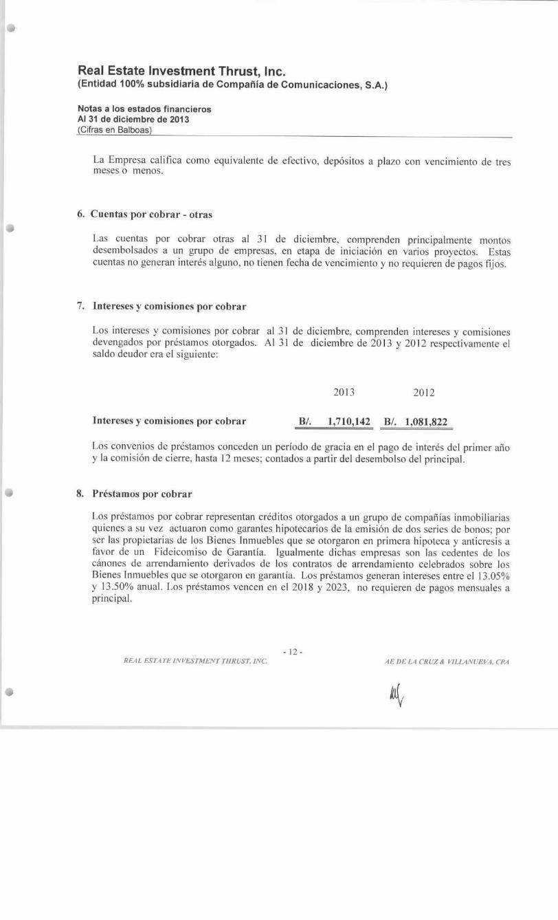
for Engineering Problemsfor Engineering Problems

Fundamentals
Difficulty in turbulent combustion modelingDifficulty in turbulent combustion modeling
Turbulent CombustionTurbulent Combustion
Large Fluctuations of all Scalar Large Fluctuations of all Scalar
and Vector Quantitiesand Vector Quantities
Problems both in Measurement Problems both in Measurement
and Computationand Computation

Fundamentals
Typical flame structures in turbulent combustionTypical flame structures in turbulent combustion
NonpremxedNonpremxedNonpremxedNonpremxed Partially PremixedPartially PremixedPartially PremixedPartially PremixedPremixedPremixedPremixedPremixed
Tight Coupling between Tight Coupling between FlameletsFlamelets (Localized Reaction Zone)(Localized Reaction Zone)
and and Turbulent Eddies (causing Mixing)Turbulent Eddies (causing Mixing)

Fundamentals
§ Favre averaged conservation equations with nonlinear terms
We need to perform averagingWe need to perform averaging
v 0kkt x
r r¶ ¶+ =
¶ ¶%
²vv vi ik ik i k
k ip g
t x x xr r t¶ ¶ ¶ ¶
+ = - + +¶ ¶ ¶ ¶%
²v wi ikk k
k i iYY Jt x xr r¶ ¶ ¶
+ = - +¶ ¶ ¶
&%
²1
1 1[ ( )v ]N
ii
ikk
k k i k
Yp hhh ht x t x x Sc x
mr r ms s=
¶¶ ¶ ¶ ¶ ¶+ = + + -
¶ ¶ ¶ ¶ ¶ ¶å%
p RTr= %
( , , )ih h Y p T=% % %
Nonlinear Convection TermNonlinear Convection Term
Nonlinear Reaction TermNonlinear Reaction Term

Fundamentals
Closure assumptions for nonlinear termsClosure assumptions for nonlinear terms
Is it OK to make assumptions valid in nonreactingturbulence or laminar flows?
²v" " tDF =- ÑF%
w exp( / )ni j aAYY T E RTF = -% % % %&
The answer is No! Then What Can We do?
(Eddy Diffusivity)
(Arrhenius in terms of Means)
DNS/LES: No/Minimal averaging
Stochastic PDF Transport: Monte Carlo
Phenomenological Modeling (RANS): Limited applicability
Conditional Averaging (RANS): CMC/LFM

Fundamentals
What is conditional averaging ?What is conditional averaging ?
§ For a fluctuating variable Φ, there exists a fluctuating variable x which is closely related with fluctuation of Φ.
X Probability Xf
1XD
2XD1Xf
2Xf
1P
2P
nXD nP nXf
1 11 ,
n n
i i ii iP P Xf f
= =
= =å å
Flame StructureFlame StructureFlame StructureFlame Structure
PDFPDFPDFPDF
Temp. DistributionTemp. DistributionTemp. DistributionTemp. Distribution

Fundamentals
What is conditional averaging ?What is conditional averaging ?
§ Ref. Chen and Kollman (Turb Reacting Flows Ch. 5, 2nd ed. 1994)
Zonal conditioning (TPF)Zonal conditioning (TPF)Zonal conditioning (TPF)Zonal conditioning (TPF) Surface conditioning (TNF)Surface conditioning (TNF)Surface conditioning (TNF)Surface conditioning (TNF)
Bimodal Variation
e.g. turb/nonturb, burned/unburned, etc.
Continuous Variation
e.g. mixture fraction, reaction progress variable

Fundamentals
Mathematical procedureMathematical procedure
Fine grained pdf : ( )hd d x h= - pdf for fluctuating : ( ) ( )P h d x h= -xxh
: Fluctuating variable: sampling variable for x
Conservation equation for an arbitrary scalar f
|Q f h=< >
( ) ( ) ( )v Dtrx r x r x¶
+Ñ × = Ñ × Ñ¶
( ) ( ) ( )v D Wtr r r r F
¶F +Ñ× F = Ñ× ÑF +
¶&
2
2( ) ( ) ( )v Nt h h hrd r d r d
h¶ ¶
+Ñ × = -¶ ¶
2 2
2 2( ) ( ) ( )Qv N Q Nt h h h hrd r d rd r d
h h¶ ¶ ¶
F +Ñ× F = -¶ ¶ ¶
| ( )Phfd f h h=< >

Fundamentals
Mathematical procedure – conditional averaged Eqns and pdfMathematical procedure – conditional averaged Eqns and pdf
N D x xº Ñ ×Ñ
( ) ( )Sc
t
t x
mrx r x xé ù¶
+Ñ × = Ñ × Ñê ú¶ ê úë û
u%
% % %%1 1
1 1 1
0
(1 )( ; )( ) (1 )
Pd
a b
a b
h hhx x x
- -
+ - + - +
-=
-òx%
2 2
22 2 2
'' ''
2( '' ) ( '' ) '' ( )Sc Sc
t t
tx x
m mrx r x x x rcé ù¶
+Ñ × = Ñ × Ñ + Ñ -ê ú¶ ê úë û
u% %
% % % % %%
|Q f h=< >
After averaging, we get
2
2( ( )) ( v ( )) ( ( ))P P N Pt h h hr h r h h r h h
h¶ ¶
+Ñ × = -¶ ¶
Assumed beta-function PDF in terms of ²2"andx x%

Fundamentals
CMC vs LFMCMC vs LFM
CMC : Based on rigorous mathematical procedure for conditional averagingConditional submodels required for conditional velocity, scalar dissipation rate, etc
LFM : Based on physical assumption of a flamelet structureFlame structure in terms of stoichiometric SDRLagrangian handling of a transient effect (RIF)Applicable range?
- Major uncertainties in many engineering combustion problems are in the PDF’s due to turbulent mixing, rather than in conditional flameletstructures.

Fundamentals
Conditional submodels – reaction and convectionConditional submodels – reaction and convection
- Reaction Term (1st order closure)
- Convection Term
Mean velocity
Linear scaling
Gradient diffusion
1 2
" "( , , ) | ( , , )(1 )i ji i T
i j
Y YT P Q P T T
QQw h w< >» + + +Y Q
Conservation of higher order conditional fluxes (Mortensen 2005)

Fundamentals
Conditional submodels – scalar dissipation rateConditional submodels – scalar dissipation rate
AMC model
Girimaji’s model
PDF integration (steady state)
Amplitude mapping closure to Gaussian reference field for homoturbulence (Pope 1991, Gao 1991)
Evolution of beta pdf according to pdf transport eq for homogeneousturbuelnce (Girimaji 1992)
Direct double integration of spatially dependent local pdf (Bilger 1999)

TNF – CMC 1D model
Schematic diagram for interation between OpenFOAM and CMC routineSchematic diagram for interation between OpenFOAM and CMC routine
CMCreactingFoam(based on OpenFOAM 1.7.x)
CMC routineCMC routine
CMC thermo-chemistry library
CMC thermo-chemistry library

TNF – CMC 1D model
Bluff body ML1 flame – case descriptionBluff body ML1 flame – case description
Slip wall
Axis
Coflow(40m/s)
Fuel jet(80m/s)
0.705m
0.07m
Description Specification
Fuel CH3OH (methanol)
Fuel jet / Bluff body radius (mm) 1.8 / 25
Fuel / Air mean Vel (m/sec) 80 / 40
Fuel Temp (K) 373
Adiabatic flame temp (K) 2260
Stoichiometric mixture fraction 0.135
“Instantaneous and mean compositional structure of bluff body stabilized nonpremixed flames”, B. B. Dally, A. R. Masri, R. S. Barlow, G. J. Fiechtner, Combustion and Flame, 114:119-148 (1998)

TNF – CMC 1D model
Bluff body ML1 flame – results (mixture fraction space)Bluff body ML1 flame – results (mixture fraction space)
Major species mass fractions with respect to the mixture fractionMajor species mass fractions with respect to the mixture fraction
Conditional mean temperature with respect to the mixture fractionConditional mean temperature with respect to the mixture fraction
O2
H2O
CO2
CH3OHO2
H2O
CO2
CH3OHO2
H2O
CO2
CH3OH

TNF – CMC 1D model
Bluff body ML1 flame – results (mixture fraction space)Bluff body ML1 flame – results (mixture fraction space)
CO mass fraction with respect to the mixture fractionCO mass fraction with respect to the mixture fraction
H2 and OH mass fractions with respect to the mixture fractionH2 and OH mass fractions with respect to the mixture fraction
H2
OH
H2
OH
H2
OH
CO CO CO

TNF – CMC 1D model
Bluff body ML1 flame – results (radial distribution)Bluff body ML1 flame – results (radial distribution)
Radial distributions of the Favre mean mixture fraction and r.m.s fluctuation of the mixture fraction
Radial distributions of the Favre mean mixture fraction and r.m.s fluctuation of the mixture fraction

TNF – CMC 1D model
Bluff body ML1 flame – results (radial distribution)Bluff body ML1 flame – results (radial distribution)
Radial distributions of the Favre mean temperature and OH mass fractionRadial distributions of the Favre mean temperature and OH mass fraction
Radial distributions of the major species mass fractionsRadial distributions of the major species mass fractions
T
OH
T
OH
T
OH
CH3OHO2
H2O
CO2
CH3OH H2O
O2
CO2
CO2
H2OO2

CI engine - CMC-ISR model
§ Conditional mean mass fraction and enthalpy equation § Conditional mean reaction rate
§ Spatially integrated conditional mean mass fractions and enthalpy equation
§ Mean mixture fraction
§ Mean mixture fraction variance
ξ : Mixture fraction
µt : Turbulent viscosity
Scξ : Schmidt number for mixture fraction ( = 0.9 )
Scξ2 : Schmidt number for mixture fraction variance (= 0.9 )
sξ : Vaporization source term for mixture fraction
C : Correlation coefficient
Governing equations of CMC modelGoverning equations of CMC model
Vaporization source termsVaporization source terms

CI engine - CMC-ISR model
Multiple flame structure considerationMultiple flame structure consideration
§ Multiple flame structures to consider combustion of the sequentially evaporated fuel groups
§ Concept of multiple flame structures
jF% (j = 1, 2, ∙∙∙, N) is the mass fraction of the j-th flame group.
§ Favre averaged mass fraction
represents the conditional mean mass fraction of the i-th species in the j-th flame group.
§ Weighting factor

CI engine - CMC-ISR model
Schematic diagram for interation between OpenFOAM and CMC routineSchematic diagram for interation between OpenFOAM and CMC routine
CMCdieselEngineFoam
(based on OpenFOAM 1.7.x)
CMC routineCMC routine
CMC thermo-chemistry library
CMC thermo-chemistry library

CI engine - CMC-ISR model
ERC diesel engine – case descriptionERC diesel engine – case description
Description Specification
Engine Caterpillar 3401E
Engine speed (rpm) 821
Bore (mm) x Stroke (mm) 137.2 x 165.1
Compression ratio 16.1
Displacement (Liters) 2.44
Combustion chamber geometryIn-piston Mexican Hat
with sharp edged crater
Max injection pressure (MPa) 190
Number of nozzle 6
Nozzle hole diameter (mm) 0.214
Spray angle (deg) 125
Cylinder head
liner
Piston
Kong S. C. et al, SAE 2003-01-1087
• 3-D sector mesh of 60 deg. with periodic boundary condition.
• Fuel spray ;Initial droplet size is determined by Rosin-Rammler distributionfunction w/ the SMD of 14 micronInjected fuel temp : 311K
• Skeletal mechanism for n-heptane44 species and 114 elementary stepsNOx chemistry included
• Initial swirl ratio ; 0.978
Operating conditions
EGR level (%) 7*, 27, 40
SOI timings (ATDC) -20, -15, -10*, -5 , 0, 5
Injection duration (deg) 6.5
* represents reference case

CI engine - CMC-ISR model
Spatial distributions of the mean temperature and fuel spraysSpatial distributions of the mean temperature and fuel sprays
ERC diesel engine – resultsERC diesel engine – results
Spatial distributions of the mean mixture fractionSpatial distributions of the mean mixture fraction

CI engine - CMC-ISR model
ERC diesel engine – resultsERC diesel engine – results
Major species mass fractions with respect to the mixture fractionMajor species mass fractions with respect to the mixture fraction
Conditional mean temperature and scalar dissipation rate with respect to the mixture fraction
Conditional mean temperature and scalar dissipation rate with respect to the mixture fraction

CI engine - CMC-ISR model
ERC diesel engine – resultsERC diesel engine – results
Pressure trace w.r.t different injection timePressure trace w.r.t different injection time

CI engine - CMC-ISR model
ERC diesel engine – resultsERC diesel engine – results
Pressure trace w.r.t different injection timePressure trace w.r.t different injection time

GAS JET MODEL
Grid dependency of standard spray modelsGrid dependency of standard spray models Schematic of two-phase spray flowSchematic of two-phase spray flow
• Representative large CFD mesh and spray volumes aredifferent
→ the momentum transfer is dampened→ gas-phase momentum is under-predicted→ resulting in under-penetration
Correct prediction of the gas-phase is crucial
[1] Abani, N. et al. An improved spray model for reducing numerical parameter dependencies in diesel engine CFD simulations. SAE Technical Paper, 2008-01-0970 (2008)
• The two-phase spray flow has two components;→ The motion of the group of droplets which forms theliquid phase and the movement of the air entrained→ The motion of the group of droplets which forms thegas phase
To reducing grid-dependency numerical errors,either of the phases could be corrected
Schematic diagram for interation between OpenFOAM and gasjet routineSchematic diagram for interation between OpenFOAM and gasjet routine
gasjetdieselFoam(based on OpenFOAM 1.7.x)
Gasjet routineGasjet routine
(OP≤x0 & OP≤2LBK)
(OP>x0 & OP≤2LBK)
(OP>2LBK)
equivalent diameter of the gas jet :
entrainment constant :
breakup length :
GAS JET MODEL

GAS JET MODEL
Injectionnozzle
Type Hole nozzle DLL-S
Number of holes 1
Hole diameter [mm] 0.2
Injection pressure Δp [MPa] 120 99
Injection duration [ms] 1.36 1.51
Fuel amount [mg] 12
Ambient gas N2
Ambient pressure [MPa] 1.5
Ambient temperature Room temperature (285 – 293K)
Ambient density [kg/m3] 17.3
Fuel N-tridecane (C13H28)
Simulation ConditionsSimulation Conditions
Experimental conditions[2]Experimental conditions[2]
ResultsResults
• Constant volume chamber(20mmX20mmX120mm)• Standard k-ε turbulence model• KH-RT breakup model• Compared spray tip penetration on various cell size
(1mm,2mm,4mm) at injection pressure 120MPa and 99Mpa
[2] Dan, T., Takagishi, S., Senda, J. & Fujimoto, H. Effect of ambient gas properties for characteristics of non-reacting diesel fuel spray. SAE paper970352 (1997)

Gas Turbine Combustor
Steady SolverSteady Solver
§ alternateReactingFoam by Markus è OpenFOAM 1.7.x(modification)
§ Steady reactingFoam, PaSR, standard k-e model
§ RK ode solver for 1step chemistry(methane/air)
§ Xeon E5530, 12 [email protected] GHz(Execution time : 6.2 h for 3000 step)
Temperature distributionTemperature distributionGrid for the gas turbine combustor Grid for the gas turbine combustor
§ 60° sector, fluid region, 6.3 million polyhedral cells(STAR-CCM+ Ver.2.10) è converting STAR-CD mesh(vrt, cel, bnd)
è converting OpenFOAM mesh(starToFoam)

NOx formation pathway
High Pressure Jet-Stirred Reactor by Rutar[3]High Pressure Jet-Stirred Reactor by Rutar[3]
[3] Rutar, T, 2000, “NOx and CO Formation for Lean-Premixed Methane-Air Combustion in a Jet-Stirred Reactor Operated at Elevated Pressure,” PhD Thesis, University of Washington, Seattle, Washington.
6.5 atm, preheated(573K)
overall residence time [ms] 0.754 4
Equivalence ratio 0.57 0.66
Inlet velocity [m/s] 408.7 102.8
Specification of the experiment§ 6.5 atm, preheated inlet(573K)§ Residence time : 0.754, 4 ms§ Standard k-e, PaSR with GRI 3.0§ 2D axi-symmetric 420 structured cell1. Premixed CH4/air è Turbulence source2. Heat loss è constant TWall
Computational grids of HP-JSR
CH4
Air
23.19 mm
Outlet

NOx formation pathway
NOx mechanismNOx mechanism
§ Irreversible § Zeldovich
(dNO/dt)ZELD = 2kN2+O[O][N2]§ N2O
(dNO/dt)N2O = 2kN2O+O[O][N2O]+ 2kN2O+H[H][N2O]
§ Prompt(dNO/dt)PROMPT = 2kN2+CH[CH][N2]
§ NNH(dNO/dt)NNH = 2kNNH+O[O][NNH]
Chemical kinetic modeling by Chemical kinetic modeling by RutarRutarChemical kinetic modeling by Chemical kinetic modeling by RutarRutar
§ Zeldovich1. N2 + O ↔ N + NO2. N + O2 ↔ NO + O3. N + OH ↔ NO + H
§ N2O1. N2 + O + M ↔ N2O + M2. N2O + O ↔ 2NO3. N2O + H ↔ NO + NH4. NH + O ↔ NO + H
§ Prompt1. N2 + CH ↔ HCN + N2. HCN + O ↔ NCO + H3. NCO + H ↔ NH + CO4. NH + H ↔ N + H25. N + OH ↔ NO + H
CFD CFD CFD CFD

NOx formation pathway
NOx mechanismNOx mechanism
Ø 4 ms case : Twall = 1700KØ 0.754 ms case : tksource = 1.0e+09 kg/ms3
è Contribution of Nitrous NO increases in high pressure condition
6.5 atm, preheated inlet(573K)
Overall residence time[ms] 0.754 4.0
Measured NO[ppmv, wet] 6.05 8.8
Approach ckm sim ckm sim
Tg [K] 1805 1902 1878 1833
Zeldovich NO[ppmv, wet] 1.0 2.98 2.96 4.06
Nitrous NO[ppmv, wet] 3.67 3.04 2.12 4.28
Prompt NO[ppmv, wet] 1.29 0.52 2.96 2.67
NNH NO[ppmv, wet] 0.58 - 1.14 -
Total NO [ppmv, wet] 6.54 6.4 9.18 8.51
NOx formation contribution by chemical kinetic modeling and numerical simulation

Conclusion
1. Conditional averaging is a powerful approach to handle the complicated problem ofturbulence-chemistry coupling in many engineering combustion problems.
2. The CMC model is implemented in Openfoam ver. 1.7.x for turbulent nonpremixedcombustion. Two different implementation strategies are employed, 1-D Eulerian for steadyTNF flames and 0-D Lagrangian with multiple flame groups for diesel engines.
3 The <c> transport model is implemented with the turbulent burning velocity specified tosimulate turbulent premixed combustion. It is applied to simulate spark ignition and turbulentflame propagation in an SI gasoline engine.
4. The KH-RT spray breakup model is extended with the gas jet model to reduce grid sizedependence due to inappropriate resolution of the gas phase around spray droplets.
5. The PaSR model in Openfoam is applied with single step chemistry for a gas turbinecombustor. The PaSR is combined with GRI 3.0 chemistry to simulate a simple combustor toanalyze relative contribution of different NOx mechanisms.
6. Currently we are having problems with the steady solver combined with multistep skeletalchemistry. There is no rezoning logic for IC engines, which incurs about twice as much morecomputation time as compared with KIVA. No valve motion logic for intake/exhaust strokes inthe current Openfoam version. No steady solver with coal particle tracking and combustion.