Embed Size (px)
Citation preview

1
Development Status and Performance Comparisons of
Environmental Barrier Coating Systems for SiC/SiC
Ceramic Matrix Composites
40th International Conference and Expo on Advanced Ceramics and Composites
January 24-29, 2016
Daytona Beach, Florida
Dongming Zhu and Bryan Harder
Environmental Effects and Coatings Branch
Materials and Structures Division
NASA John H. Glenn Research Center
Cleveland, Ohio 44135, USA

2
Light-Weight SiC/SiC Ceramic Matrix Composite (CMC) –
Environmental Barrier Coating (EBC) Development
Combustor Vane Blade
Monolithic/Hybrid
Ceramic Nozzles/Blades
Metal components with TBCs Light-weight SiC/SiC CMC
components
— Enabling next generation turbine engine hot-section technology: increased
materials temperature capability and improved future engine performance
— EBCs are critical to long-term environmental durability and life of Si-based
ceramic engine components

3
NASA Environmental Barrier Coating System Development – For
Turbine Engines
• Emphasize temperature capability, performance and durability for next generation for next generation vehicle airframe or engine systems
• Increase Technology Readiness Levels for component system demonstrations
2900°F
(T41)
Gas TBC Bond
coat
Metal
blade3200°F
(T41)
Gas TBC Bond
coat
Metal
blade3200°F
(T41)
Baseline metal
temperature
300°F
increase
Gas EBC Bond
coat
CMC
airfoil
Tsurface
Tsurface
Current metal turbine
airfoil system
State of the art metal turbine
airfoil system 2500°F TBCs
2700-3000°F CMC
turbine airfoil systems
200-500°F
increase
Tsurface
2500°F TBCs2700-3000°F
EBCs
Thin turbine
coating
development
2200°F TBCs2400°F CMCs
2700°F CMCs

4
Fundamental Recession Issues of CMCs and EBCs
Exposure Time (hrs)
0 20 40 60 80 100
SiC
Wt.
Lo
ss (
mg
/cm
2)
-15
-10
-5
0
1385 C
1446 C
1252 C
1343 C
SiO2 + 2H2O(g) = Si(OH)4(g)
Recession rate = constant xV1/2
P(H2O)
2/(P
total)1/2
Combustion gas
SiO2 + 2H2O(g) = Si(OH)4(g)
Combustion gas
Cooling air
(a) (b)
0.001
0.01
0.1
1
0.0005 0.00055 0.0006 0.00065 0.0007 0.00075 0.0008
AS800
SN282
SiC/SIC CMC
La2Hf
2O
7
HfO2 (doped)
RE-Hf-luminosilicates
BSAS
Spec
ific
wei
ght
chan
ge,
mg/c
m2-h
1/T, K-1
Supersonics EBC stability development goal - 2005
1300
Temperature, °C
14001500 12001600
SiC/SiC under high velocity
Rare earth silicates
BSAS Baseline

5
Outline─ Environmental barrier coating systems: design approach for
stability
─ Next generation environmental barrier coating systems for CMC
airfoils and combustors
• NASA coating technologies – advanced composition and system
development─ Fundamental research emphasis in understanding degradation,
property evaluation, and performance modeling
─ Multi-component, multi-layer and composite systems
• EBC processing: plasma spray, electron beam-physical vapor
deposition and plasma spray-physical vapor deposition
approaches
• Advanced testing methodologies and simulated engine heat flux
and stress testing
─ Laser high heat flux test rig and coating thermal conductivity
─ High temperature durability tests
─ Summary and Conclusions

6
Advanced Environmental Barrier Coating and
Architecture Development
— High temperature and environmental stability
— Lower thermal conductivity
— Balance designs of low thermal expansion, high strength and high strain tolerance
— High toughness
— Excellent resistance to thermal-mechanical loading, impact and erosion
— Interface, grain boundary stability and compatibility
— Dynamic characteristics to resist harsh environments and with self-healing capability
High temperature capable, high strength coatings
Energy dissipation and chemical
barrier interlayer
Environmental barrier
Ceramic matrix composite (CMC)
Nano-composite bond coat
Multilayer Architecture due to Performance Requirements

7
Advanced Environmental Barrier Coating Systems:
Coating Material System Developments and Architecture
• High-stability multi-component ZrO2/HfO2, Hafnium-Rare Earth (RE) silicates, or
Hafnium-Rare Earth (RE) aluminosilicate composites
• Alternating Composition Layered Composite (ACLC) and Sublayer EBCs
systems
– Advanced multi-component and RE silicate EBCs
– Oxide-Si composite bond coats, in particular, HfO2-Si bond coats
– Self-healing and protective coating growth capability
Multi-component RE and/or RE/Hf/Zr silicates
Ceramic composite bond coats
Interlayer: Compositional layer graded or composite systems
SiC/SiC CMCs
Low expansion high toughness HfO2/ZrO2, RE-HfO2-(Alumino)silicates
HfO2 and HfO2 composites
Doped mullite
with ACLC
(Hf rich bands)
Doped HfO2+Si and mullite/Si composite bond coat
(High temperature capable with self-healing)
Increased
SiO2 activity
Increased dopant RE/Transition
metal concentrations & increased
Al/Si ratio

8
Advanced Environmental Barrier Coating Systems
200 mm
Material Systems Temperature
capability
Thermal
expansion
Resistance to
oxidation and
combustion
environment
Mechanical
stability
HfO2-RE2O3 ~3000°C 8-10x10-6 m/m-K Excellent Excellent
HfO2-Rare Earth
silicates
~1900-2900°C 8-10x10-6 m/m-K Excellent Excellent
Rare Earth Silicates ~1800-1900°C 5-8.5x10⁻⁶ m/m-K Good Good
Rare earth –
aluminates and
Alumino silicates
~1600-1900°C 5-8.5x10⁻⁶ m/m-K Good Good
HfO2-Si and RE-Si
bond coat
Up to 2100°C 5-7x10⁻⁶m/m-K Good Excellent

9
EBC Processing using Atmospheric Plasma-Spray (APS)
and Hybrid Plasma Spray / Electron Beam - Physical
Vapor Deposition (EB-PVD) Coatings
Plasma-spray processing of
environmental barrier coatings
200 mm
Early generation hybrid environmental
barrier coatings systems processed
with combined Plasma Spray and EB-
PVD processing
EB-PVD Advanced HfO2
Plasma spray ytterbium silicate
Plasma spray HfO2-Si

10
EBC Processing using Plasma Spray and EB-PVD
HfO2-Si bond coat
Oerlikon Metco Triplex Processed Advanced EBCs
HfO2-Si bond coat
Directed Vapor EB-PVD Processed Advanced EBCs

11
EBC Processing using Plasma Spray - Physical Vapor
Deposition (PS-PVD)─ NASA advanced PS-PVD coating processing using Sulzer technology
─ EBC is being developed for next-generation SiC/SiC CMC turbine airfoil coating processing
• High flexibility coating processing – PVD, CVD and/or splat coating processing
• High velocity vapor, non line-of-sight coating processing for complex-shape components
NASA Hybrid PS-PVD coater system
PS-PVD processed
coatings
Nozzle section view Mid section view End section (sample side) view
Vapor ZrO2-
Y2O3 coatingSplat/partial
vapor Yb2Si2O7
10 mm
HfO2-Si bond
coat

12
Laser High Heat Flux Approach
– Turbine level high-heat-flux tests crucial for CMC coating system developments
– Real-time thermal conductivity measurments
– Advanced complex combined mechanical loading conditions and environments
incorporated
T
Dis
tan
ce
fro
m s
urf
ac
e
Heat flux
cooling
Turbine: 450°F across 100 microns
Combustor:1250°F across 400 microns
Test rig
Thermal gradients:

13
Real-Time Thermal Conductivity Measurements
and Damage Monitoring
Surface flow

14
Plasma Spray EBC Processing and Heat Flux Testing
for CMC Component EBC Validations
0.0
0.5
1.0
1.5
2.0
2.5
3.0
0.0
0.5
1.0
1.5
2.0
2.5
3.0
0 20 40 60 80 100 120
EBC System 6, 1360°C
EBC System 1, 1500°C
EBC System 2, 1500°C
EBC System 3, 1500°C
EBC System 4, 1500°C
EBC System 5, 1500°C
EBC System 6, 1500°C
EBC System 6 Inner Diameter (ID) liner coating, 1500°C
Th
erm
al
co
nd
ucti
vit
y,
W/m
-K
Th
erm
al
co
nd
ucti
vit
y,
W/m
-K
Time, hours
Failure
FailureFailure
─ Advanced plasma sprayed multicomponent HfO2-rare earth silicate with HfO2-Si based
environmental barrier coating optimized and down-selected
─ Thermal conductivity ranged from 0.4 – 1.7 W/m-K
Laser heat flux test under thermal
gradients

15
Thermal Conductivity of PS-PVD Yb2Si2O7 Coatings For
Process Optimization
0.00 0.50 1.00 1.50 2.00 2.50 3.00 3.50
Yb2Si2-xO7-x System 1
Yb2Si2-xO7-x System 2
Yb2Si2-xO7-x System 3
Yb2Si2-xO7-x System 4
Yb2Si2-xO7-x System 5
Yb2Si2-xO7-x System 6
Yb2Si2-xO7-x System 7
k0
k2
Thermal conductivity, W/m-K
breakdown
0.0
0.5
1.0
1.5
2.0
2.5
3.0
0 10 20 30 40 50 60
b/a=0.05
b/a=0.2
b/a=0.25
Ther
mal
conduct
ivit
y, W
/m-K
Porosity, %
Coating System 2: porosity 16% modeled vs 13% measured
Coating System 3: porosity 28% modeled
Coating system 4: porosity 18% modeled
Coating system 6: porosity 20% modeled
Coating 2
Coating 3
Coating 4
Coating 6
─ Processing and microstructural optimizations,
aiming at achieving coating stability and
maintaining lower thermal conductivity
System 2
Thermal conductivity modeled using FEM

16
PS-PVD Ytterbium Silicate EBC Tested in Heat Flux
Conditions
0.0
0.5
1.0
1.5
2.0
2.5
3.0
3.5
4.0
0
200
400
600
800
1000
1200
1400
1600
0 10 20 30 40 50 60
kcera
TsurfaceTinterfaceTbackqthru
Th
erm
al c
on
duct
ivit
y,
W/m
-K
Tem
per
ature
, °C
Time, hours
Tinterface=1120°CTsurface=1400°C
Tback=920°C
Three layer HfO2-ytterbium silicate-Si
completed 50hr laser heat flux thermal
conductivity-durability tests in air and
steam
─ Demonstrated initial durability of HfO2-ytterbium silicate-silicon at 1400-1500°C test
temperatures in air and laser heat flux steam tests
─ Thermal conductivity ranged from 0.6 to 2.5 W/m-K
─ Achievable low thermal conductivity and unique structures with coatings
Laser heat flux steam test

17
PS-PVD Ytterbium Silicate EBC Tested in Heat Flux
Conditions - Continued
─ Demonstrated initial durability of ytterbium silicate
with advanced HfO2-Si bond coats at 1400-1500°C
test temperatures in air and laser steam tests
─ Thermal conductivity ranged from 0.6 to 2.5 W/m-K
─ Some sintering led more significant thermal
conductivity increases
PS-PVD processed Ytterbium/HfO2-Si
bond coat
50 mm
PS-PVD processed composite HfO2-Si
bond coat
0
2
4
6
8
10
0
200
400
600
800
1000
1200
1400
1600
0 5 10 15 20 25
kcera
Tsurface = 1482°CTinterface = 1420°CTback=1310°C
Th
erm
al c
ond
uct
ivit
y, W
/m-K
Tem
per
atu
re, °C
Time, hours
Laser heat flux test

18
Composite EBCs Considered for Improved Stability –
Process also developed for EBC systems
0 50 100 150 200 250 300 350
Yb2Si2O7/Yb2SiO5
Multi-component HfO2(t',m)+Yb2Si2O7/Yb2SiO5 30:70
Multi-component HfO2(t',m)+Yb2Si2O7/Yb2SiO5 50:50
Multi-component HfO2(t',m)+Yb2Si2O7/Yb2SiO5 70:30
Multi-component HfO2(t',m)
Biaxial strength, MPa
- Layered and nano-composite designs incorporated in various processing
approaches
- Advanced composite systems shown to improve the temperature capability and
recession resistance
- Improved mechanical properties for erosion and impact resistance
- Improved CMAS resistance
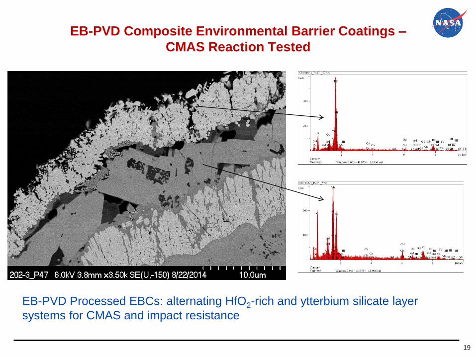
19
EB-PVD Composite Environmental Barrier Coatings –
CMAS Reaction Tested HfO2-Si bond coat
EB-PVD Processed EBCs: alternating HfO2-rich and ytterbium silicate layer
systems for CMAS and impact resistance

20
Advanced NASA 2700°F HfO2-Si and Rare Earth-Si Based
Bond Coats
SiC
RESi(O)
RE2Si2O7-x
20 mm
F
G
EDS F
EDS G
Microstructure of a HfO2-doped (Yb,Y)Si(O)
bond coat
EDS A
EDS C EDS B
- Continued improvements in processing
robustness and composition
optimization
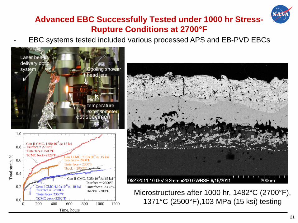
21
Advanced EBC Successfully Tested under 1000 hr Stress-
Rupture Conditions at 2700°F
- EBC systems tested included various processed APS and EB-PVD EBCs
Cooling shower
head jets
Test specimen
High
temperature
extensometer
Laser beam
delivery optic
system
To
tal
stra
in, %
0.0
0.2
0.4
0.6
0.8
1.0
0 200 400 600 800 1000 1200
Time, hours
Tsurface = 2700°F
Tinterface= 2500°F
TCMC back=2320°F
Tsurface = ~2500°F
Tinterface= 2350°F
TCMC back=2200°F
Gen II CMC, 1.98x10⁻⁷
/s; 15 ksi
Gen II CMC, 7.35x10⁻⁸
/s; 15 ksi
Gern I CMC 4.10x10⁻⁸
/s; 10 ksiTsurface =~2500°F
Tinterface=~2350°F
Tback=~2200°F
Tsurface = 2400ºF
Tinterface = 2300ºF
Tback = 2050ºC
Gen I CMC, 7.19x10⁻⁸
/s; 15 ksi
Microstructures after 1000 hr, 1482°C (2700°F),
1371°C (2500°F),103 MPa (15 ksi) testing

22
Advanced EBC-CMC Fatigue Test with CMAS:
Successfully Tested 300 h Durability in High Heat Flux
Fatigue Test Conditions - A thin EB-PVD turbine airfoil EBC system with advanced HfO2-rare earth silicate
and GdYbSi (controlled oxygen activity) bond coat tested at TEBC-surface 1537°C,
Tbond coat 1480°C, Tback CMC surface 1250°C
- Fatigue Stress amplitude 69 MPa, at mechanical fatigue frequency f=3Hz, stress
ratio R=0.05
- Low cycle thermal gradient fatigue 60min hot, 3min cooling
Strain amplitude
1537°C, 69MPa (10ksi), 300 h fatigue (3 Hz, R=0.05) on
14C579-011001_#8 CVI-MI SiC/SiC (with CMAS)
Fatigue strain-time plot
Fatigue temperature-time plot

23
Advanced EBC Fatigue Creep-Fatigue of EBCs-CMCs in
Complex Heat Flux and Simulated Engine Environments
0
50
100
150
200
250
0 0.1 10 1000 100000 10000000
10-7
10-5
0.001 0.1 10 1000
Max
imu
m s
tres
s, M
Pa
Fatigue cycles
High temperature strength data
Fatigue or creep hot time, hours
EBC 2700F+; CMC temperature labeled (2550-2700F)
2550F2700F
• Long-term creep and fatigue validated EBCs and CMCs at various loading levels
• Demonstrated advanced 1482°C (2700°F) EBC and bond coat capabilities in
complex environments
• Advanced coatings have minimized environment degradations of CMCs,
demonstrating durability in fatigue and CMAS environments
Stress-oxidation and stress-CMAS environmental testing summary

24
Summary and Conclusions
• Advanced EBCs being developed and evaluated using APS, hybrid APS/EB-PVD, EB-
PVD and, PS-PVD
─ Achieved advanced composition designed EBCs
─ Significantly expanding envisioned high performance coating architecture development
─ Demonstrated initial durability
• Advanced, high temperature testing approaches showed significant advantages in
the development of advanced environmental barrier coating systems
─ Simulated engine thermomechanical conditions
─ Simulated environment conditions
─ Real time thermal conductivity, stability and durability
─ Capable quantifying the EBC degradation and performance
25
Acknowledgements
The work was supported by NASA Fundamental Aeronautics Program (FAP)
Transformational Tools and Technologies Project.
The authors would like to acknowledge the contributions and helpful discussions from
the following:
• Ron Phillips (Vantage Partners, LLC), mechanical testing
• Terry McCue (SAIC/NASA GRC, SEM/EDS)
• Joy Buehler (Vantage Partners, LLC, Met Lab)
• James A. DiCarlo, James L. Smialek, Janet Hurst, Dennis Fox, Robert A. Miller,
and Nate Jacobson (NASA GRC)
NASA Fundamental Aeronautics Program (FAP)