Embed Size (px)
Citation preview
Published Manual Number/ECN: ME6DMCS1BE/2006112N• Publishing System: TPAS• Access date: 3/13/2006• Document ECN's: Latest Available
Schematic/Electrical Parts—
Device Master ControllerP.C. Device MasterMark 4 Controls
PELLERIN MILNOR CORPORATION POST OFFICE BOX 400, KENNER, LOUISIANA 70063-0400, U.S.A.

Please ReadAbout the Manual Identifying Information on the CoverThe front cover displays pertinent identifying information for this manual. Most important, arethe published manual number (part number) /ECN (date code). Generally, when a replacementmanual is furnished, it will have the same published manual number, but the latest available ECN.This provides the user with the latest information applicable to his machine. Similarly alldocuments comprising the manual will be the latest available as of the date the manual wasprinted, even though older ECN dates for those documents may be listed in the table ofcontents.
When communicating with the Milnor factory regarding this manual, please also provide theother identifying information shown on the cover, including the publishing system, access date,and whether the document ECN’s are the latest available or exact.
References to Yellow Troubleshooting PagesThis manual may contain references to “yellow pages.” Although the pages containingtroubleshooting procedures are no longer printed on yellow paper, troubleshooting instructions, ifany, will be contained in the easily located “Troubleshooting” chapter or section. See the table ofcontents.
Trademarks of Pellerin Milnor CorporationThe following, some of which may be used in this manual, are trademarks of Pellerin MilnorCorporation:
Ampsaver® Dye-Extractor® Gear Guardian® Milnet® Staph-Guard®
Autolint® Dyextractor® Hands-Off® Milnor® System 4®
Auto-Purge® E-P Express® Hydro-Cushion® Miltrac System 7®
Autovac E-P OneTouch® Mildata® Miltron Totaltrol®
CBW® E-P Plus®
Comments and SuggestionsHelp us to improve this manual by sending your comments to:
Pellerin Milnor CorporationAttn: Technical PublicationsP. O. Box 400Kenner, LA 70063-0400
Fax: (504) 469-1849
Table of Contentsfor ME6DMCS1BE/2006112N
Device Master Controller P.C. Device Master Mark 4 Controls
Page Description Document/ECN
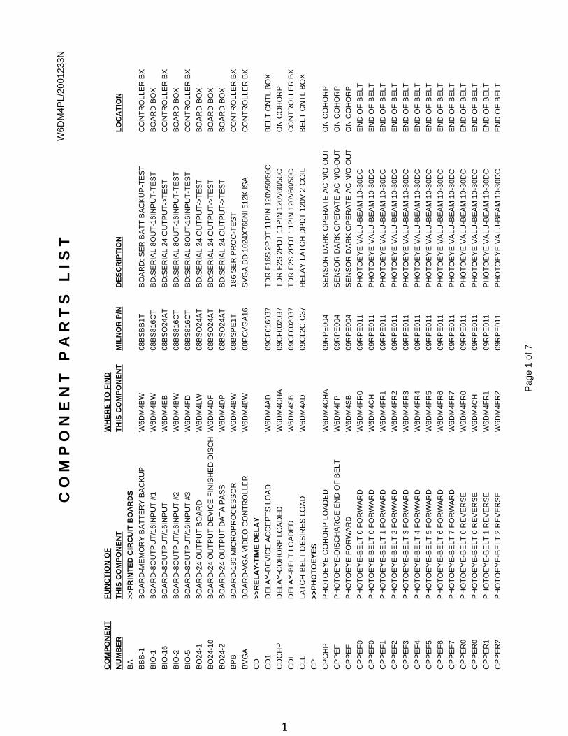
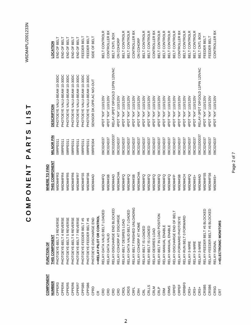
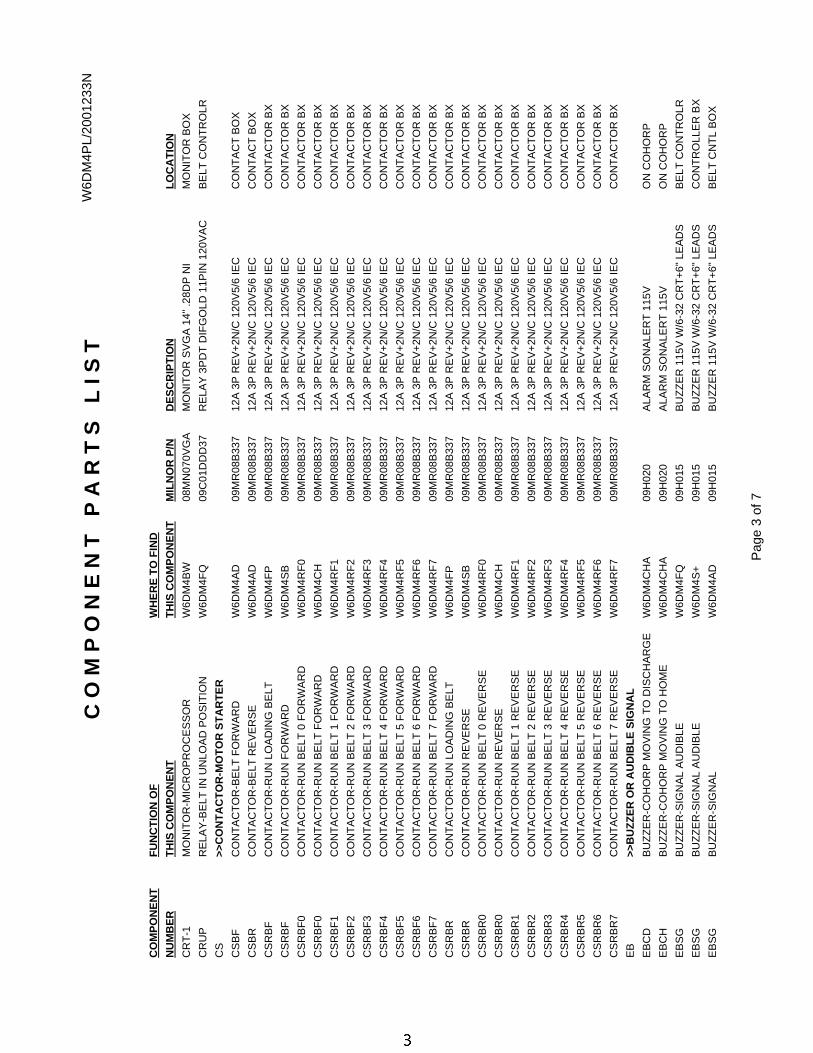
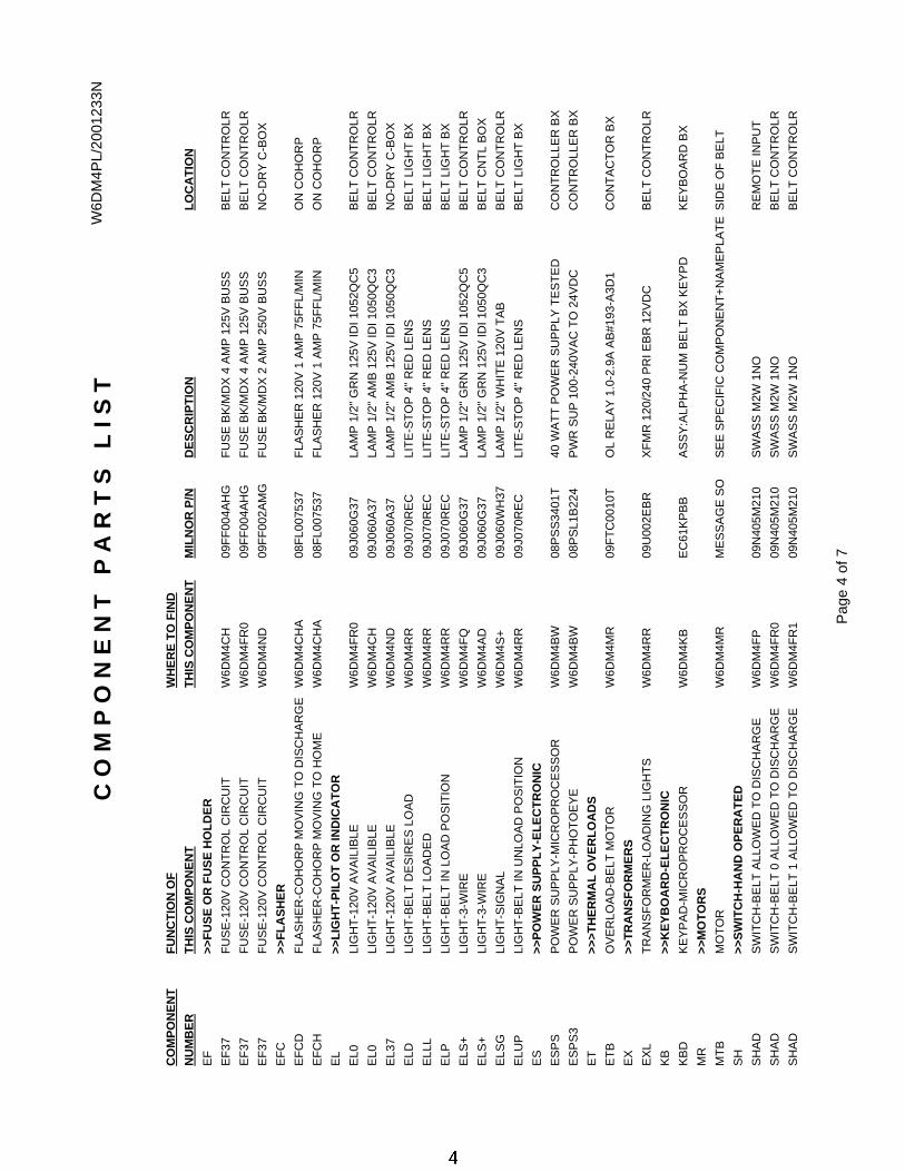
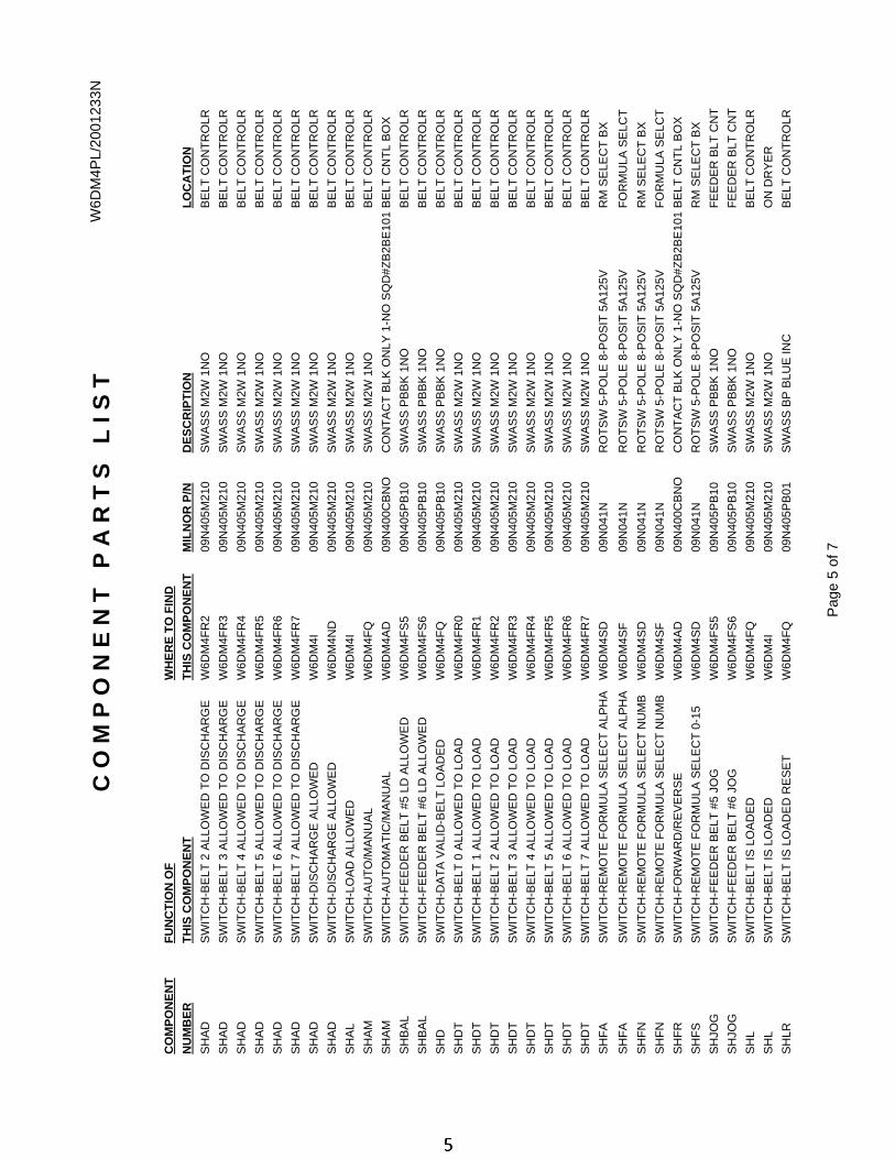
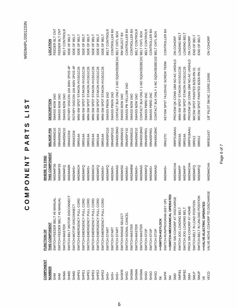
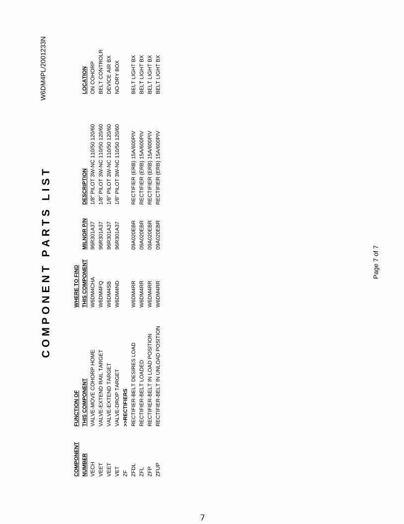
1 Component Parts List W6DM4PL/2001233N
9 Warranty BMP720097/92732A
11 How to Order Parts BMP720097R/72332A
12 How to Use Electrical Schematics MSFD0106AE/2004414V
22 On-Site Control Connections for Device Master, PC Device Master, Linear Costa & Linear Costa Master BIYCDI01/20021226
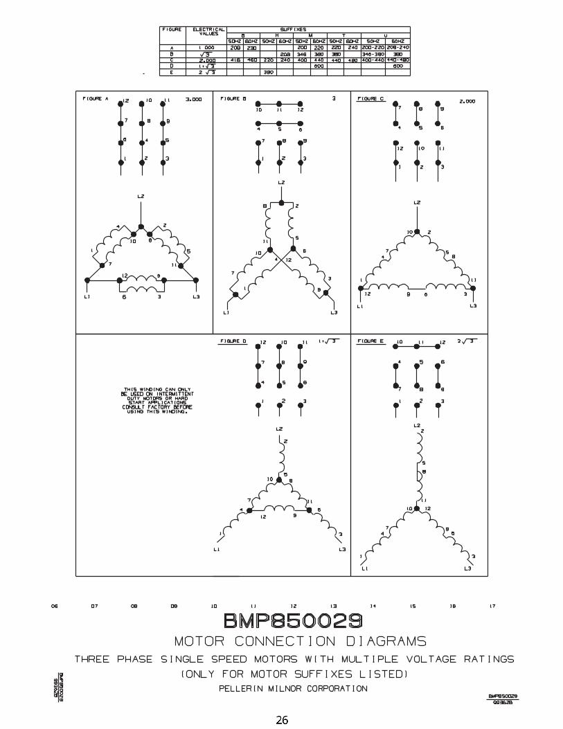
26 3 Phase Motor Connection Diagram BMP850029/99362B
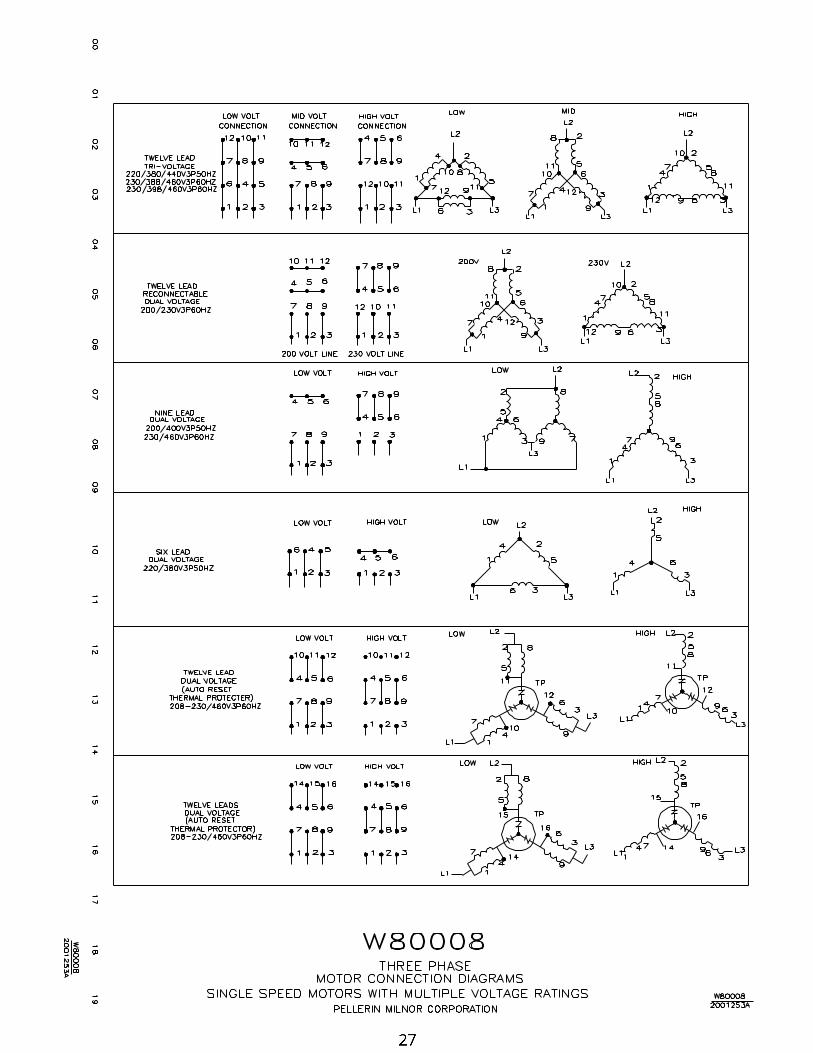
27 3P Motor Diagram-Multivolt W80008/2001253A
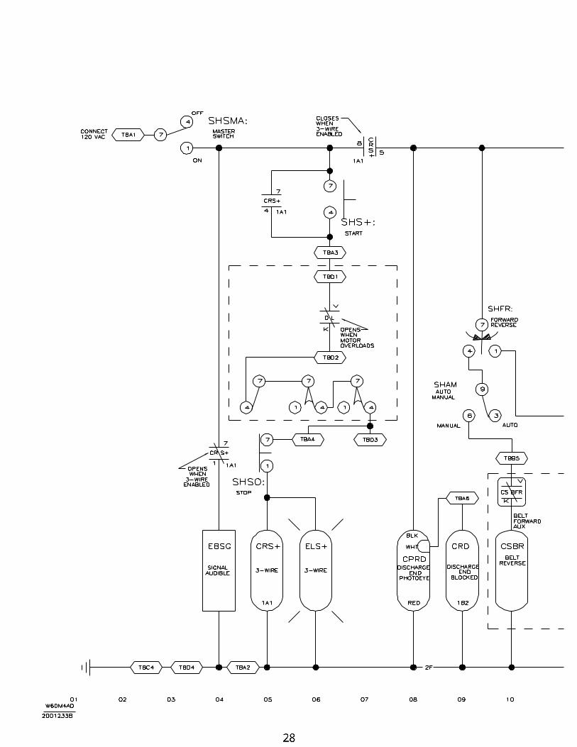
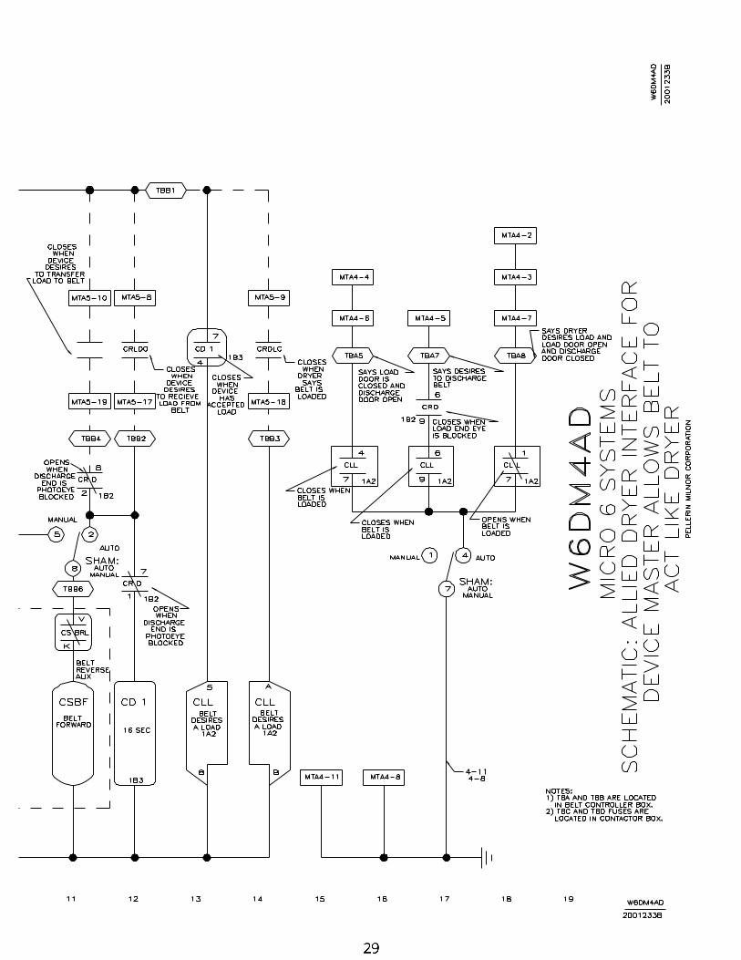
28 Allied Dryer Interface (Belt acts like Dryer) W6DM4AD/2001233B
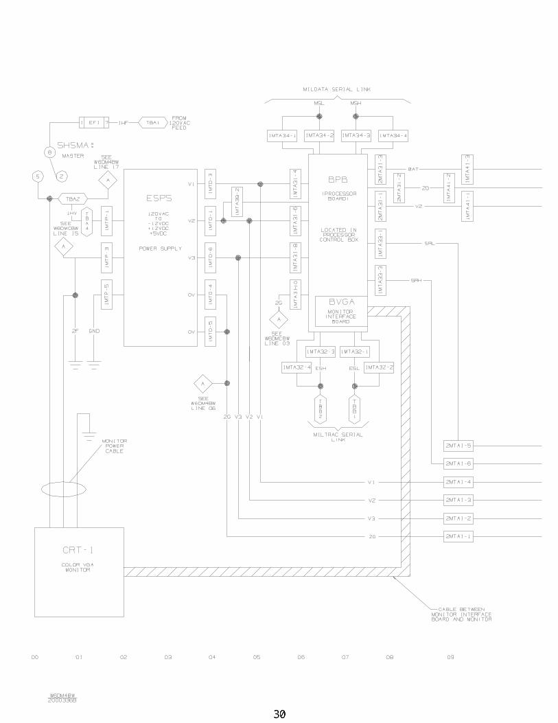
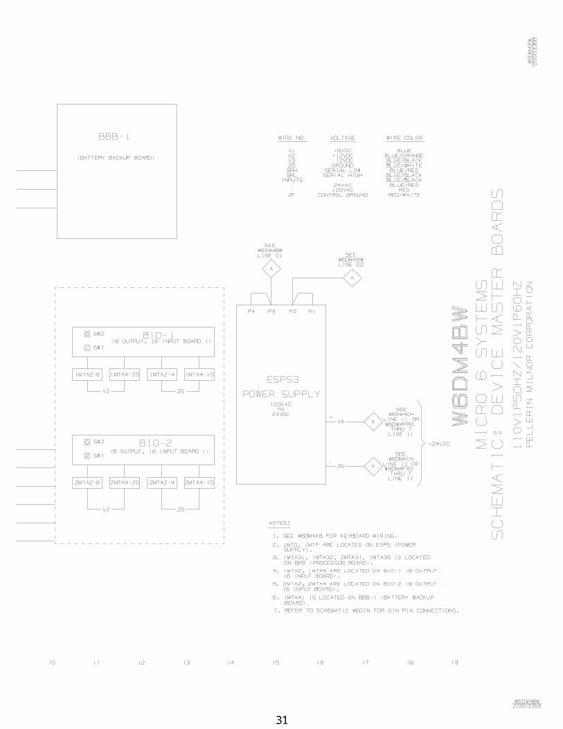
30 Board to Board Wiring W6DM4BW/2000336B
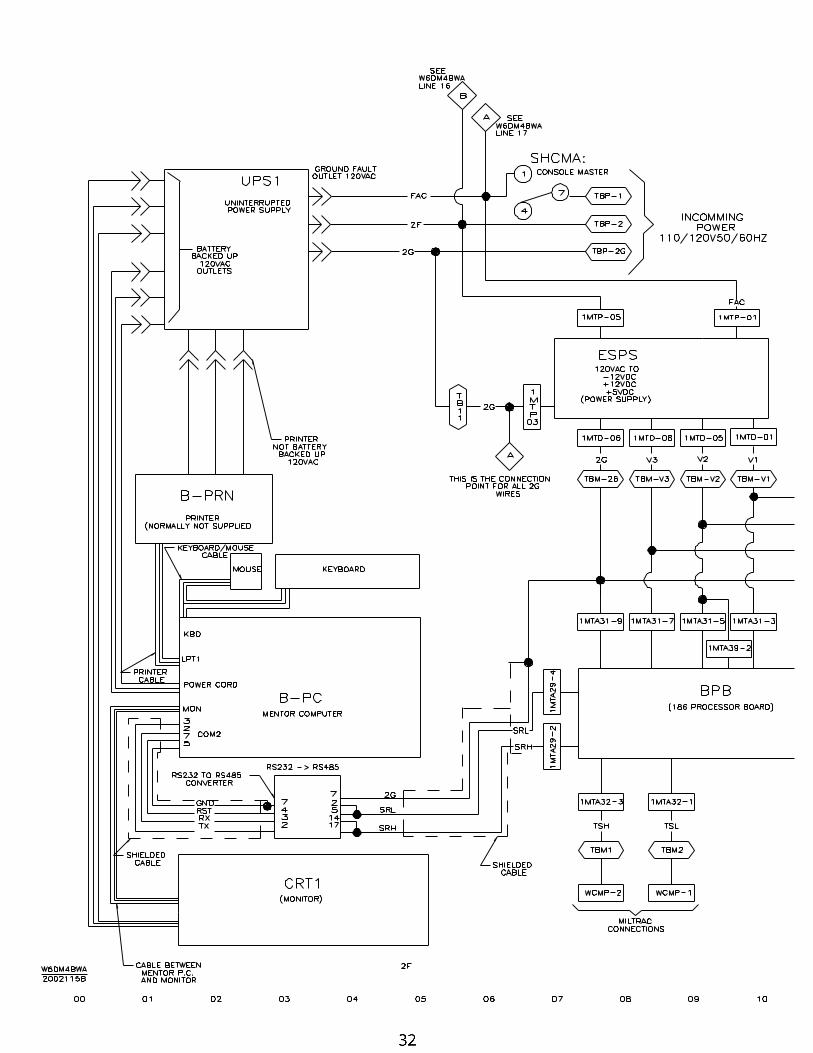
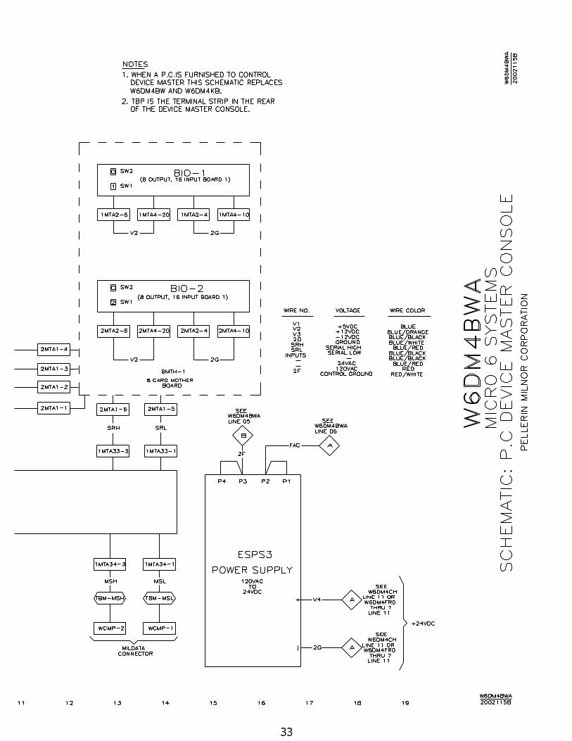
32 P.C. + Board to Board Wiring W6DM4BWA/2002115B
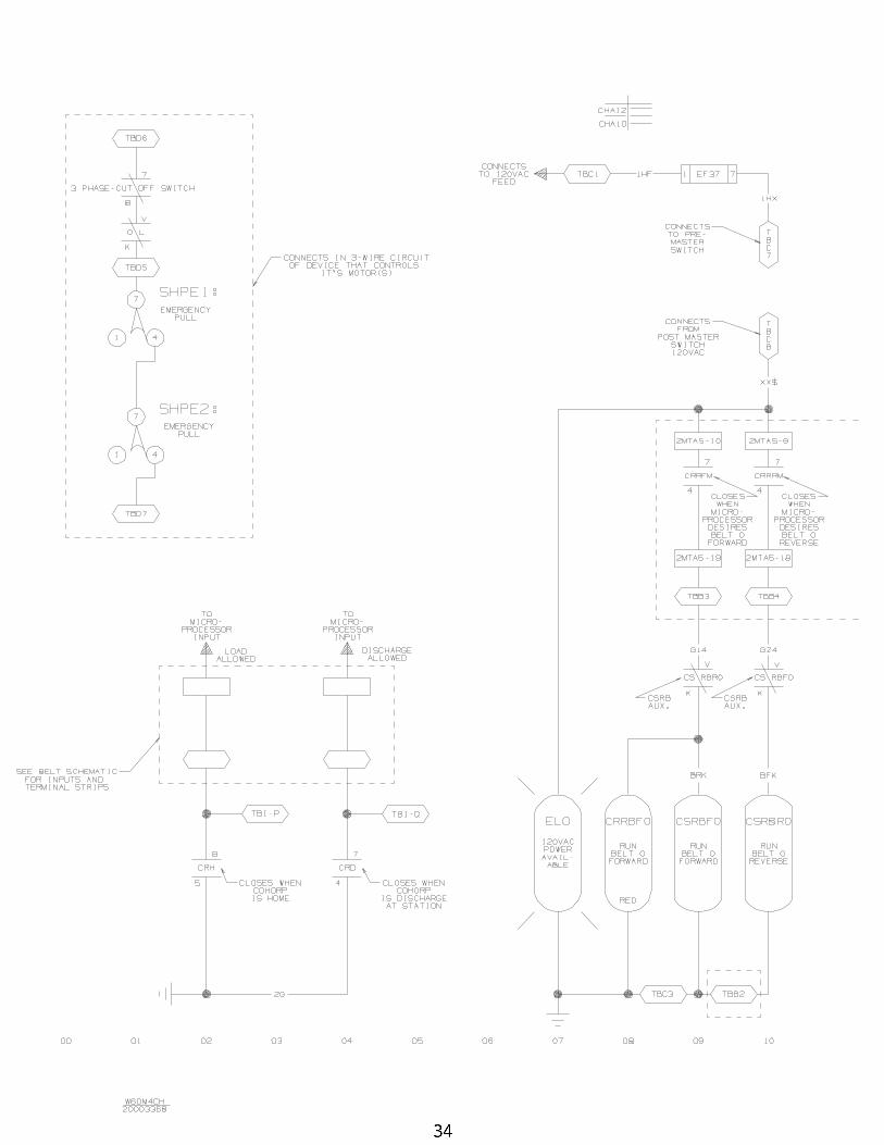
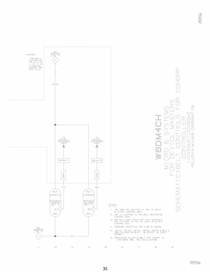
34 Belt Controls for COHORP W6DM4CH/2000336B
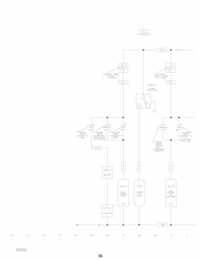
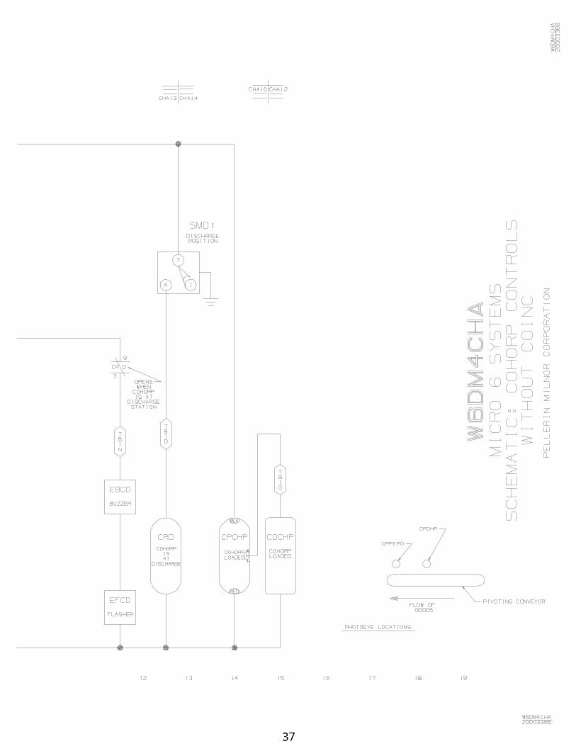
36 COHORP Controls without COINC W6DM4CHA/2000336B
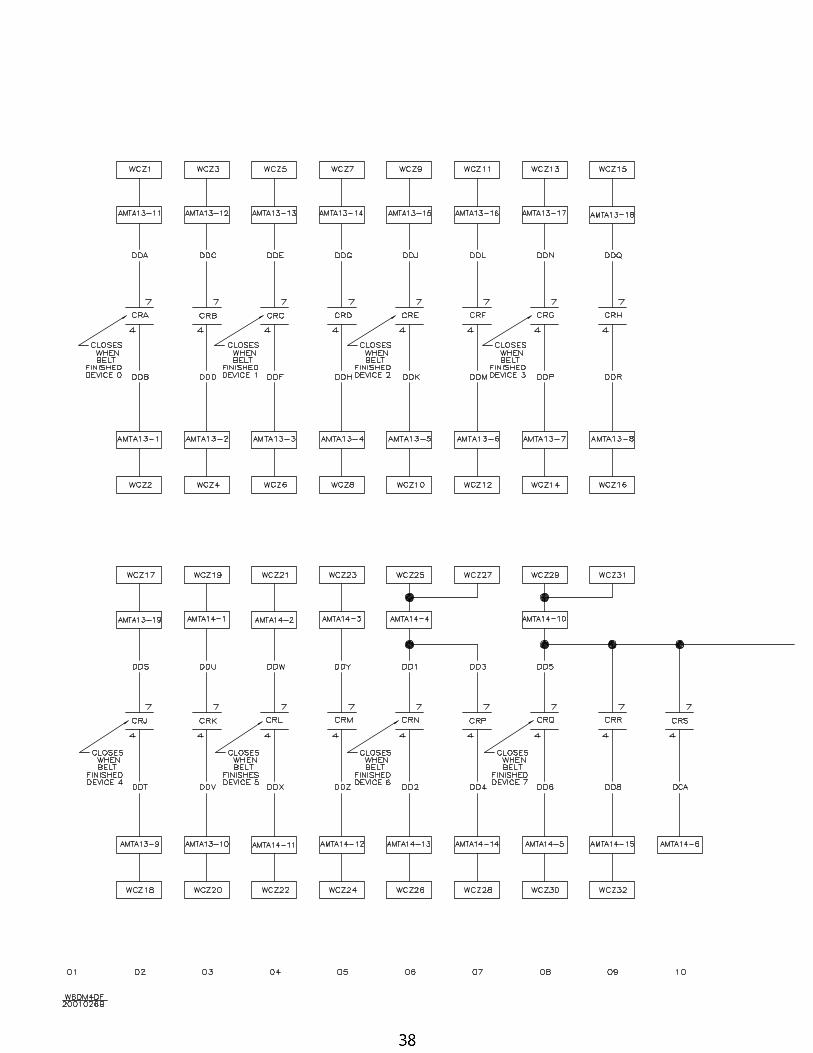
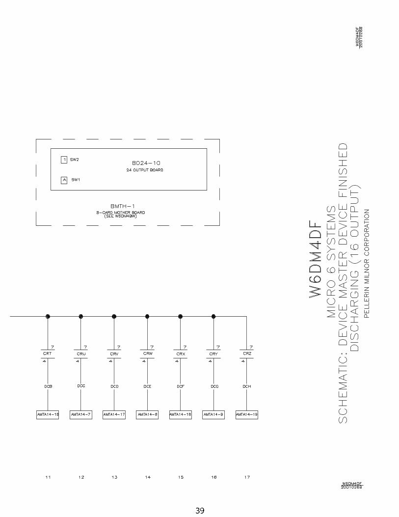
38 Device Finished Discharging (16 Outputs) W6DM4DF/2001026B
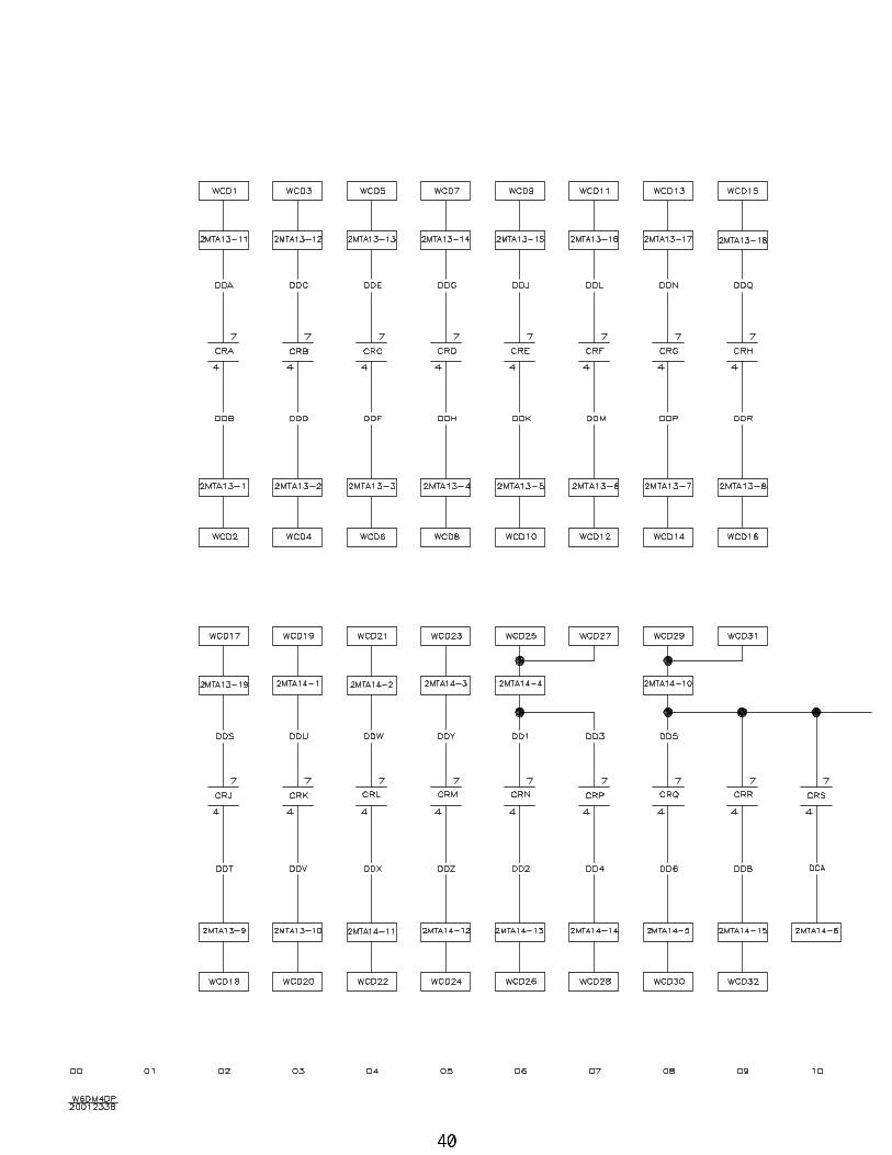
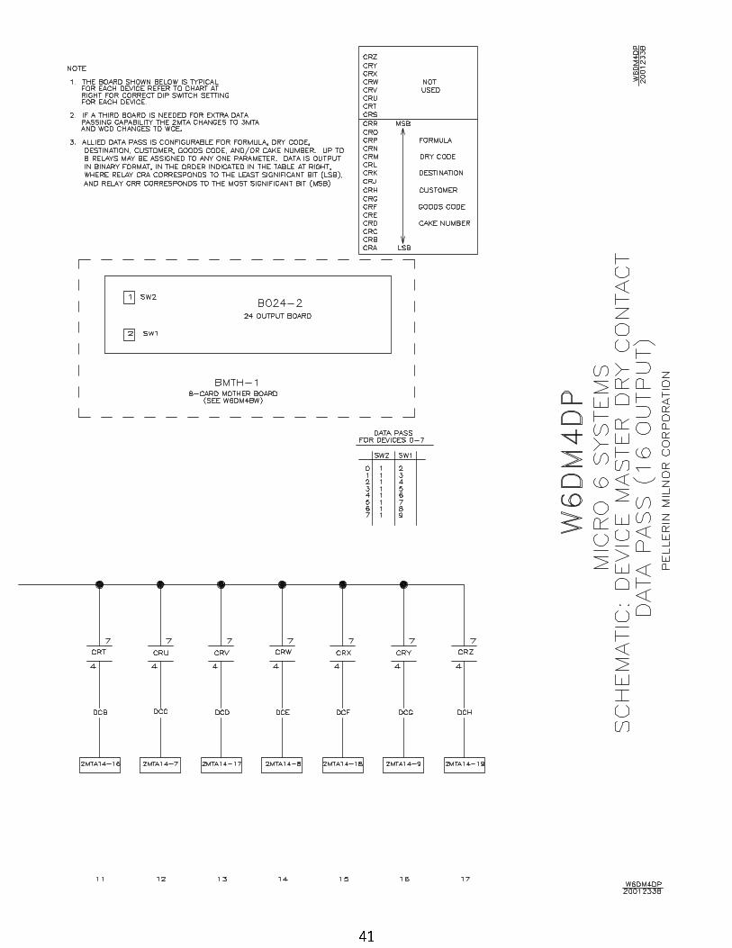
40 Data Pass Dry Contacts (16 Output) W6DM4DP/2001233B
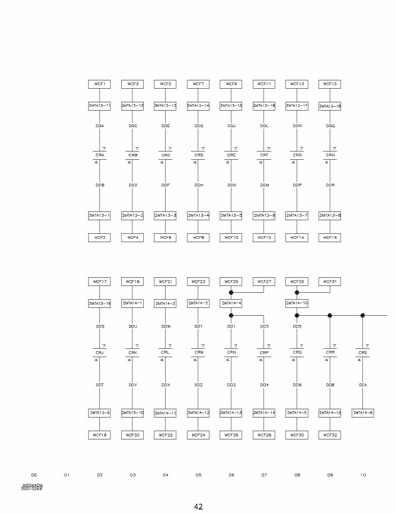
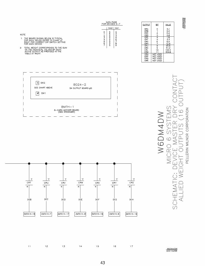
42 Allied Weight W6DM4DW/2001026B
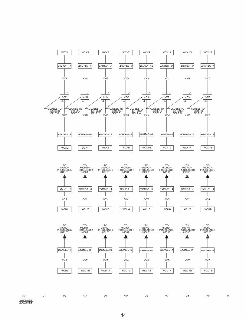
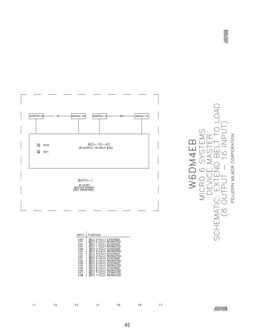
44 Extend Belt to Load (8 Out/16 In) W6DM4EB/2002165B
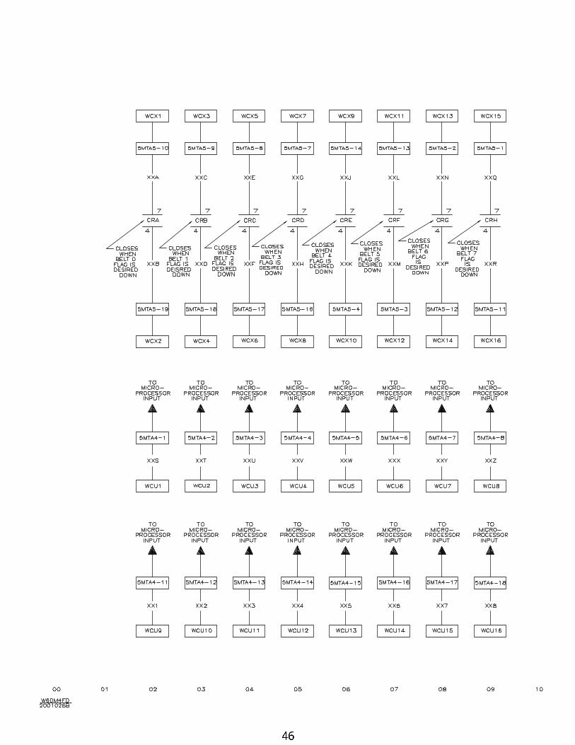
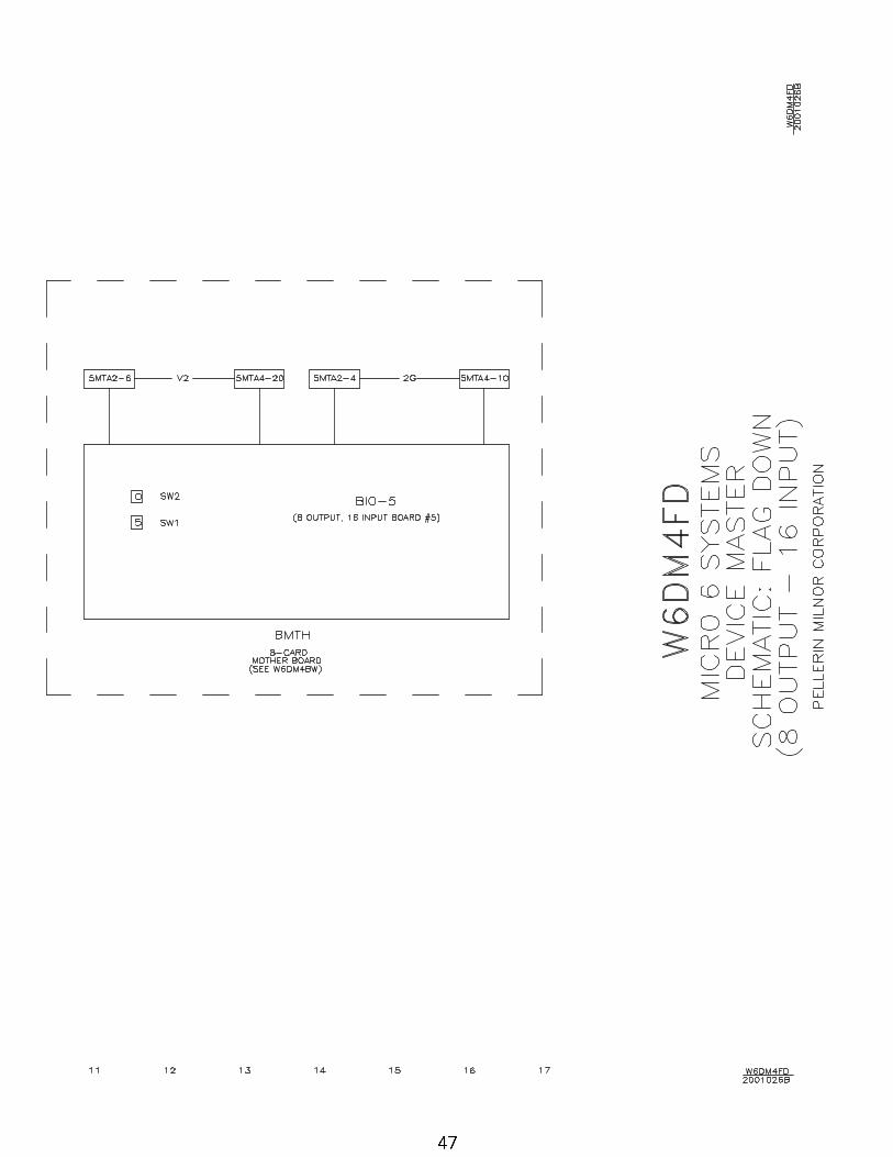
46 Flag Down (8 Out/ 16 In) W6DM4FD/2001026B
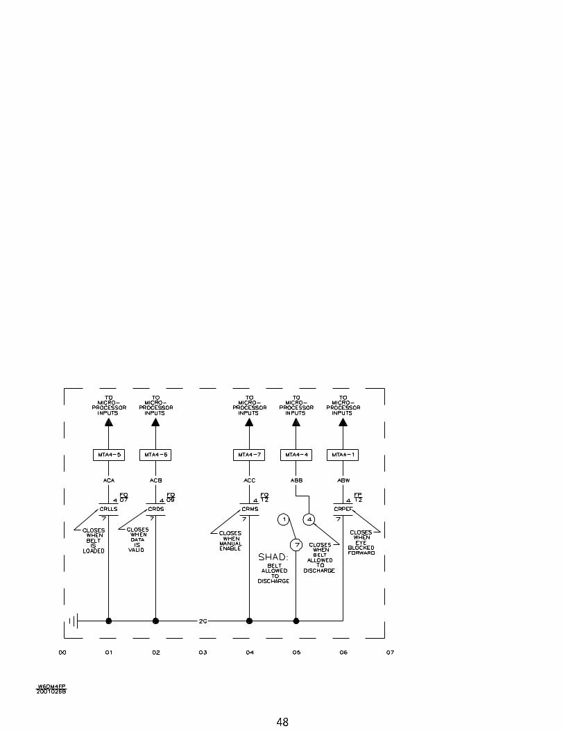
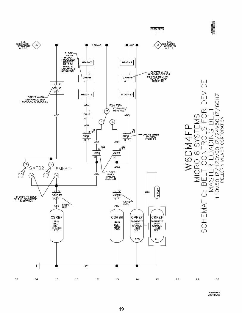
48 Belt Controls for Loading Belt W6DM4FP/2001026B
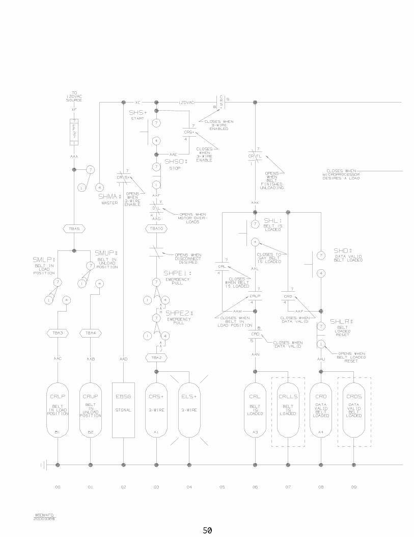
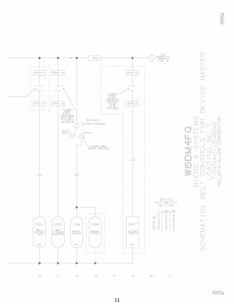
50 Belt Controls for Loading Belt W6DM4FQ/2000336B
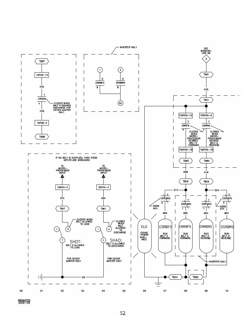
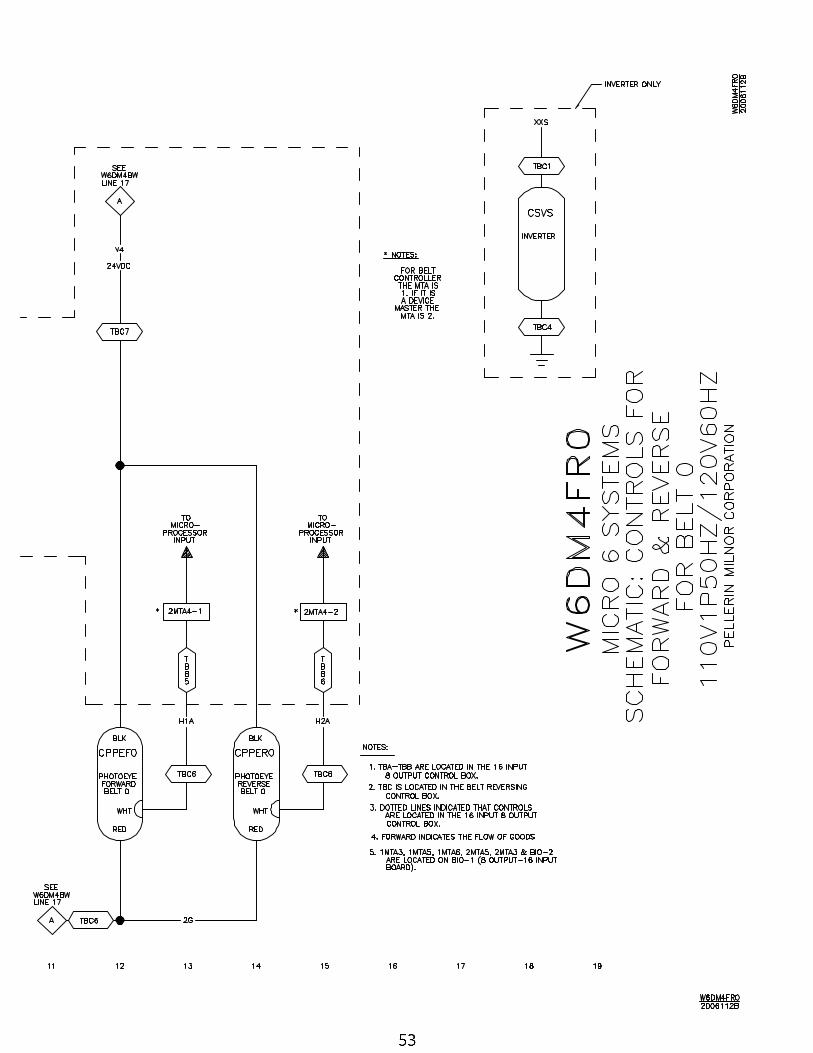
52 Belt 0 Controls Forward/Reverse W6DM4FR0/2006112B
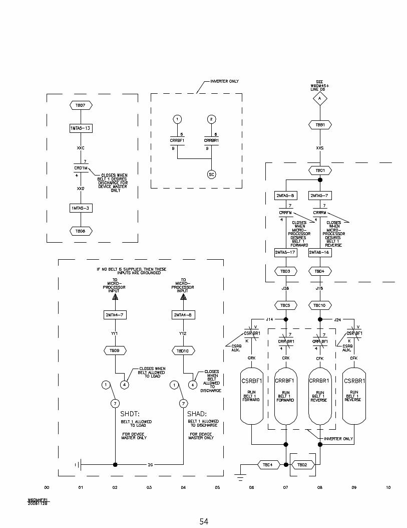
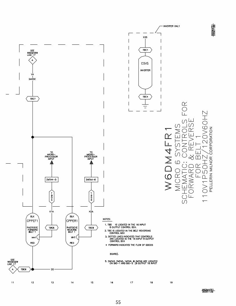
54 Belt 1 Controls Forward/Reverse W6DM4FR1/2006112B
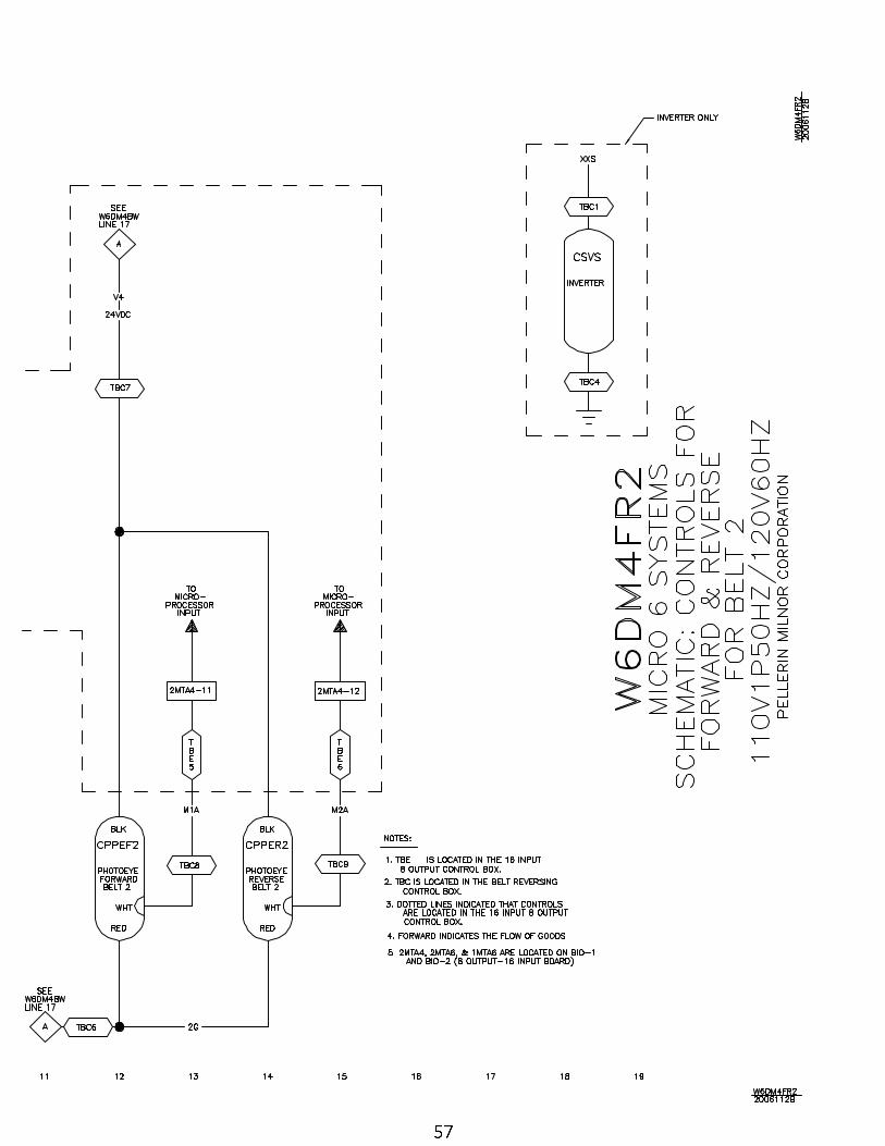
56 Belt 2 Controls Forward/Reverse W6DM4FR2/2006112B
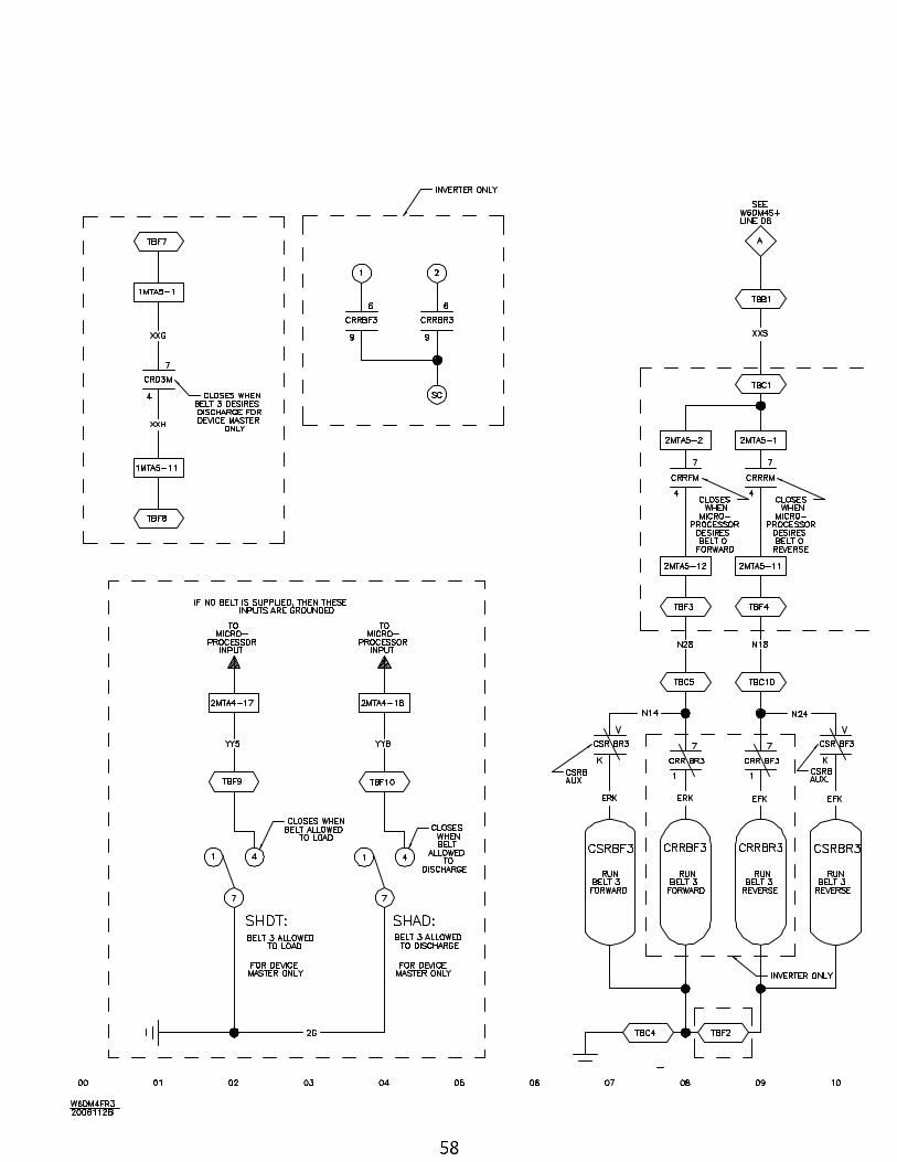
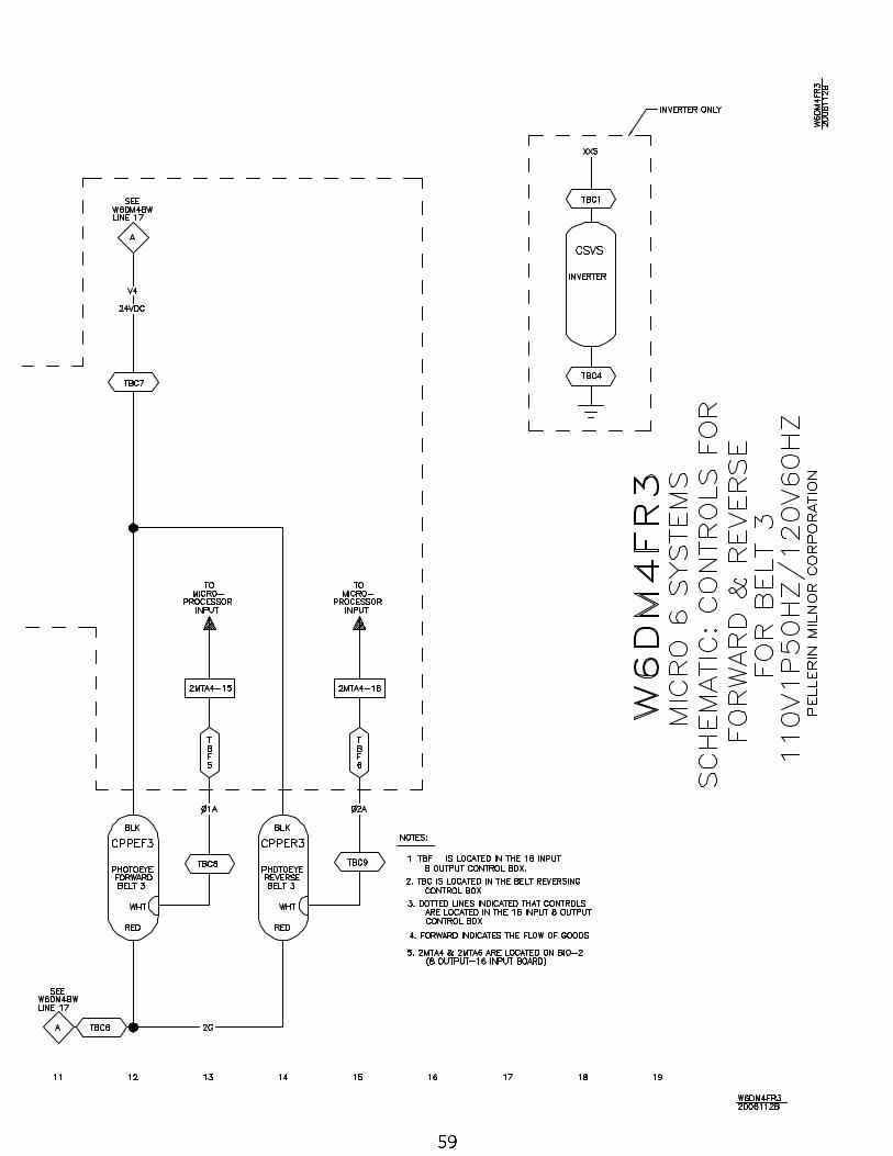
58 Belt 3 Controls Forward/Reverse W6DM4FR3/2006112B
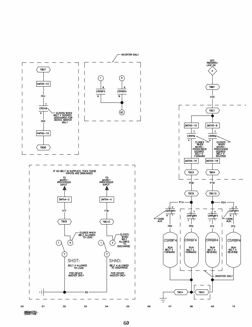
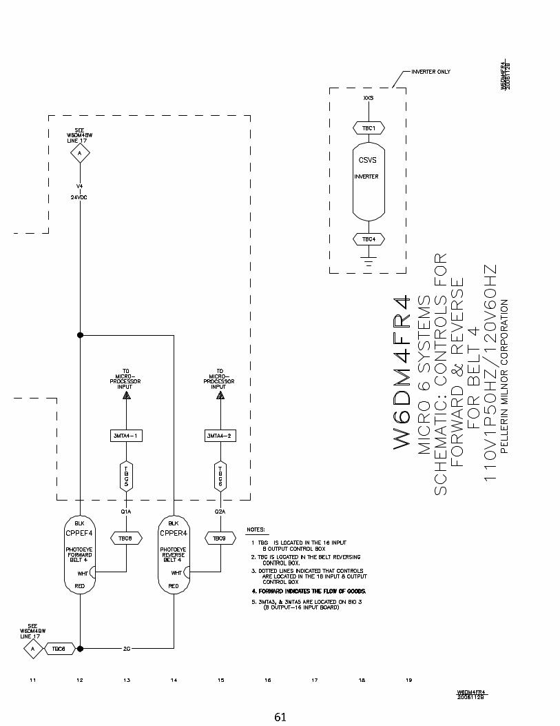
60 Belt 4 Controls Forward/Reverse W6DM4FR4/2006112B
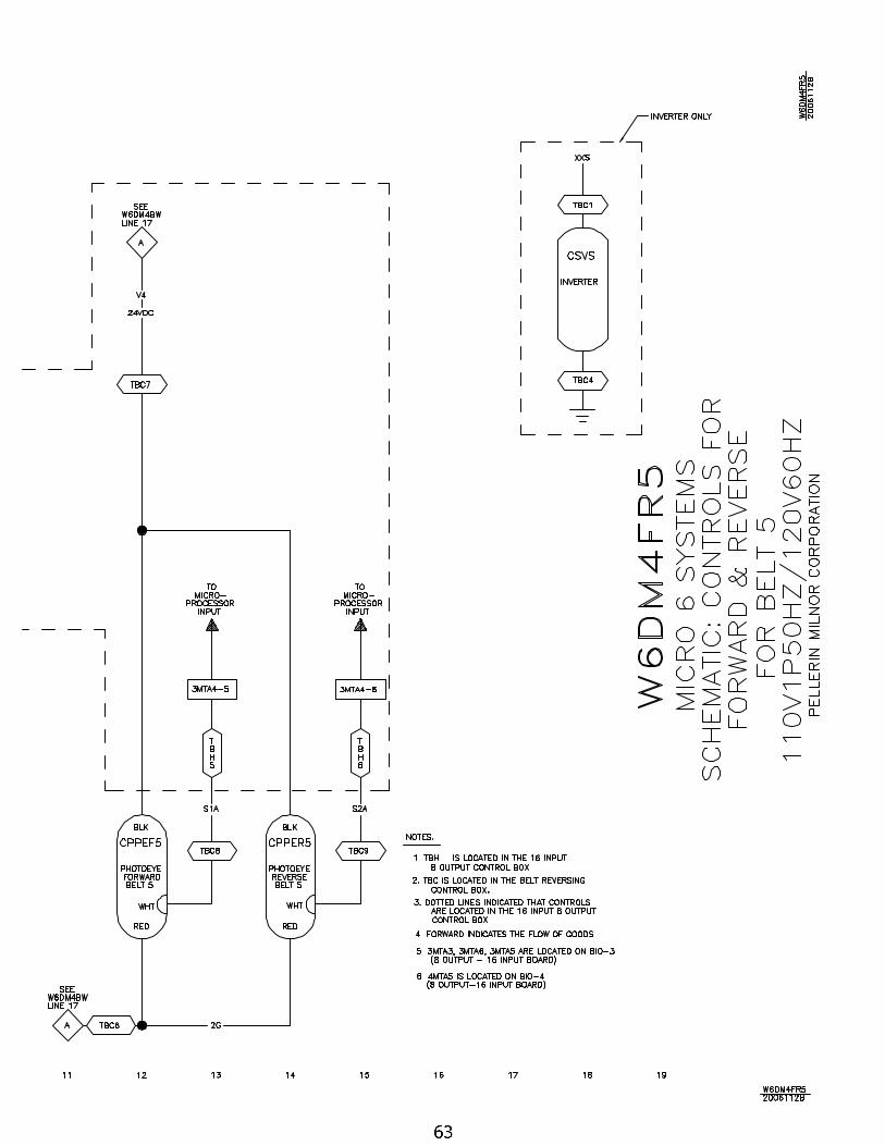
62 Belt 5 Controls Forward/Reverse W6DM4FR5/2006112B
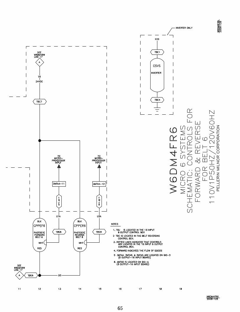
64 Belt 6 Controls Forward/Reverse W6DM4FR6/2006112B
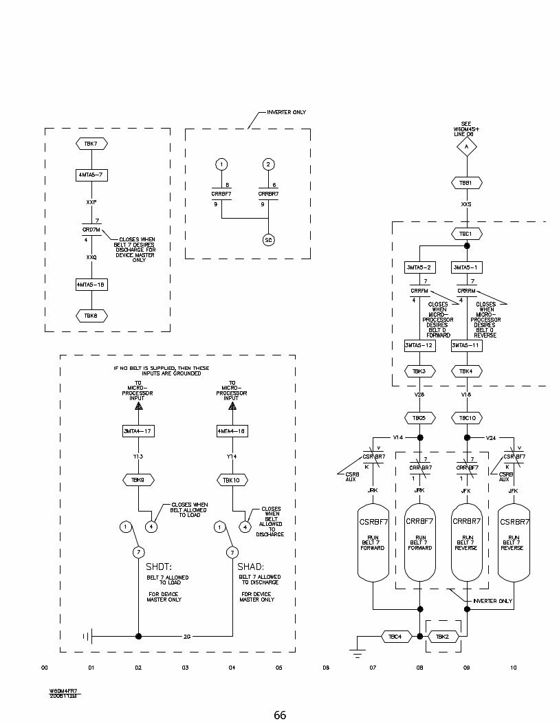
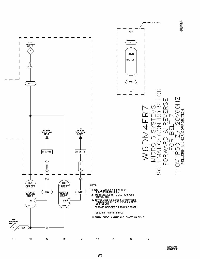
66 Belt 7 Controls Forward/Reverse W6DM4FR7/2006112B
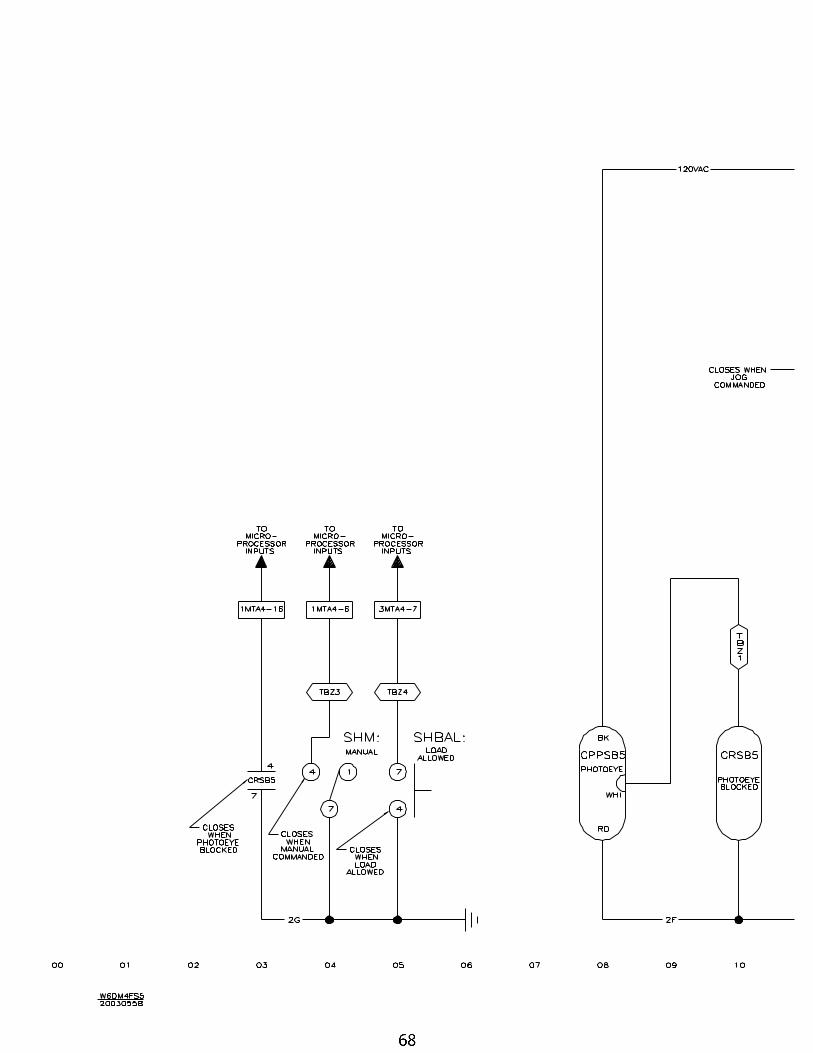
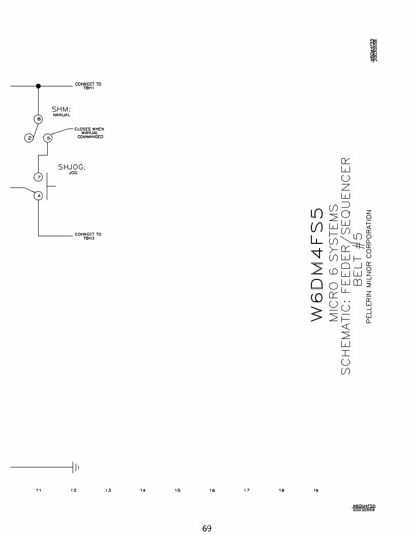
68 Feeder / Sequencer Belt 5 W6DM4FS5/2003055B
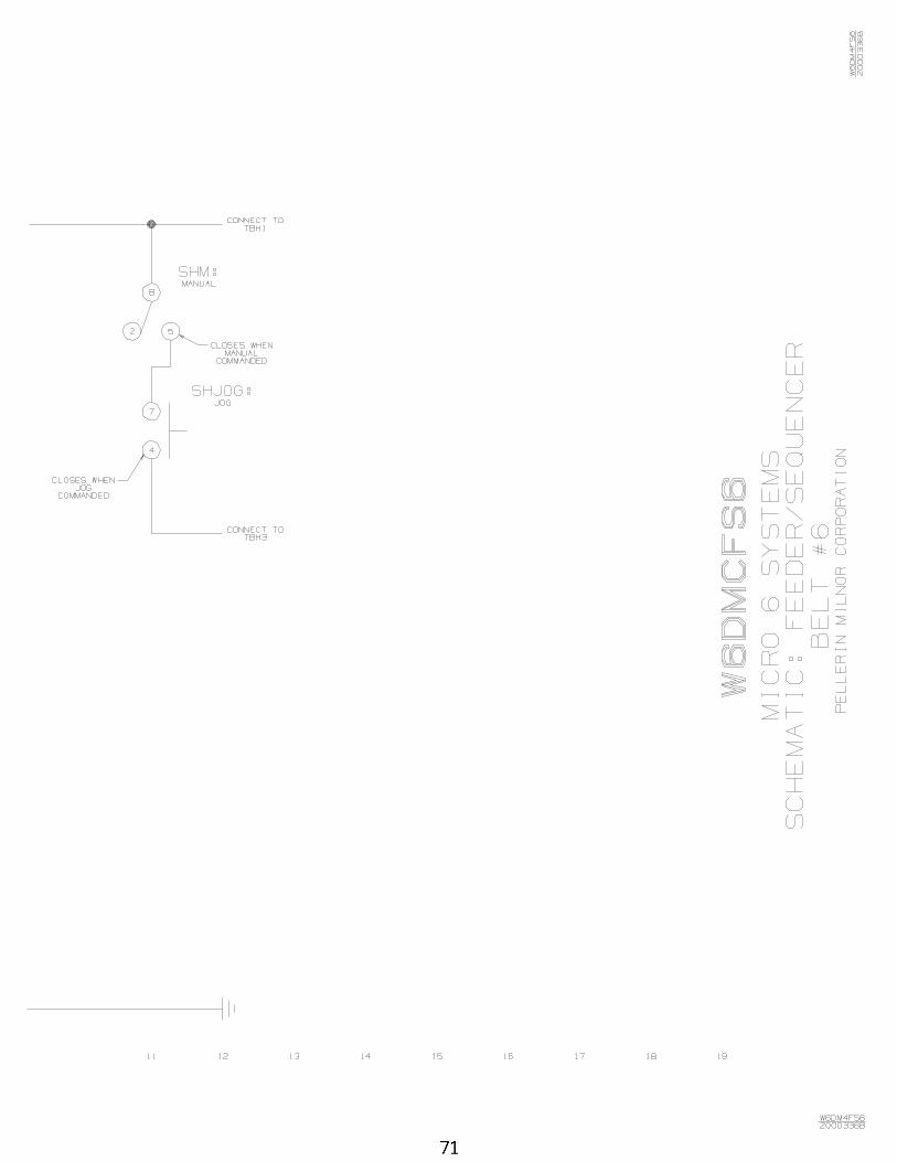
70 Feeder / Sequencer Belt 6 W6DM4FS6/2000336B
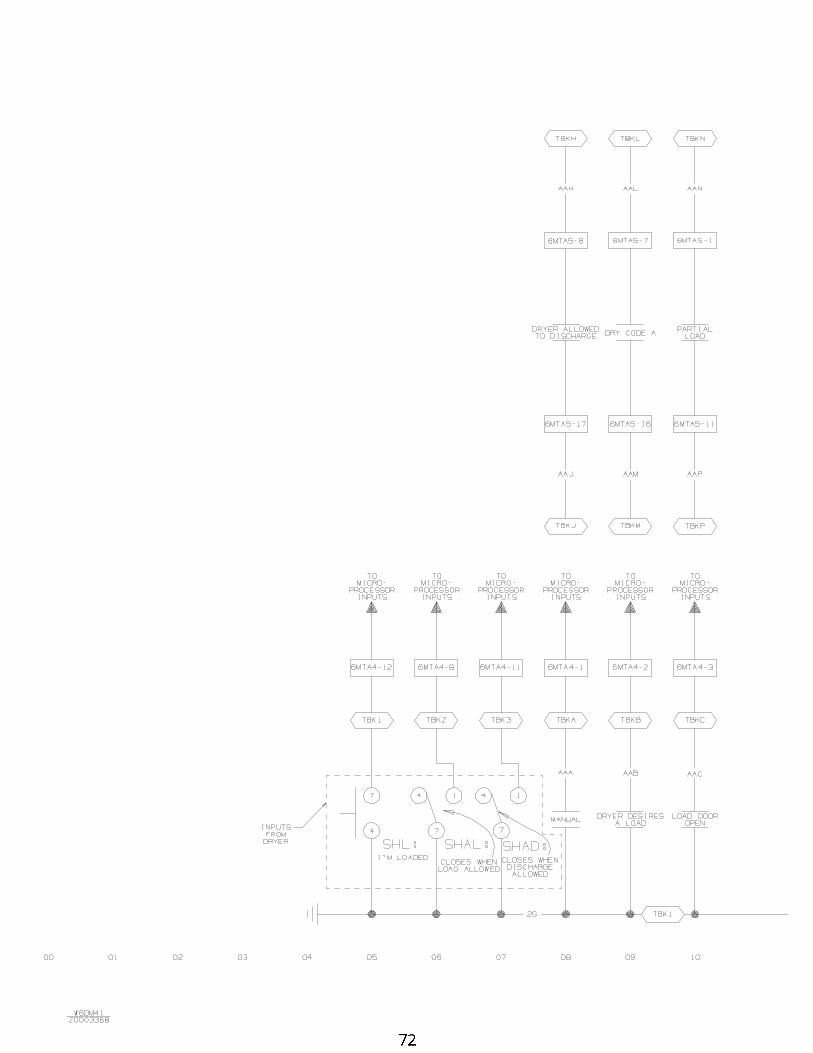
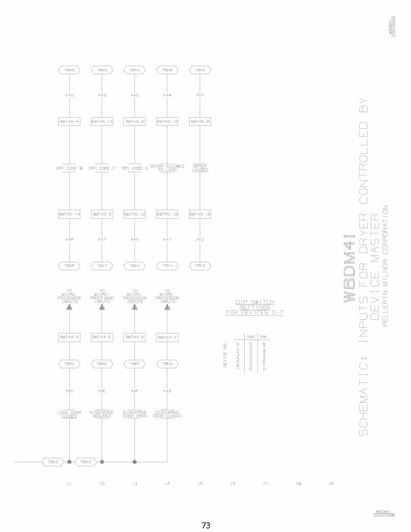
72 Inputs/Outputs-Dryer controlled by Device Master W6DM4I/2000336B
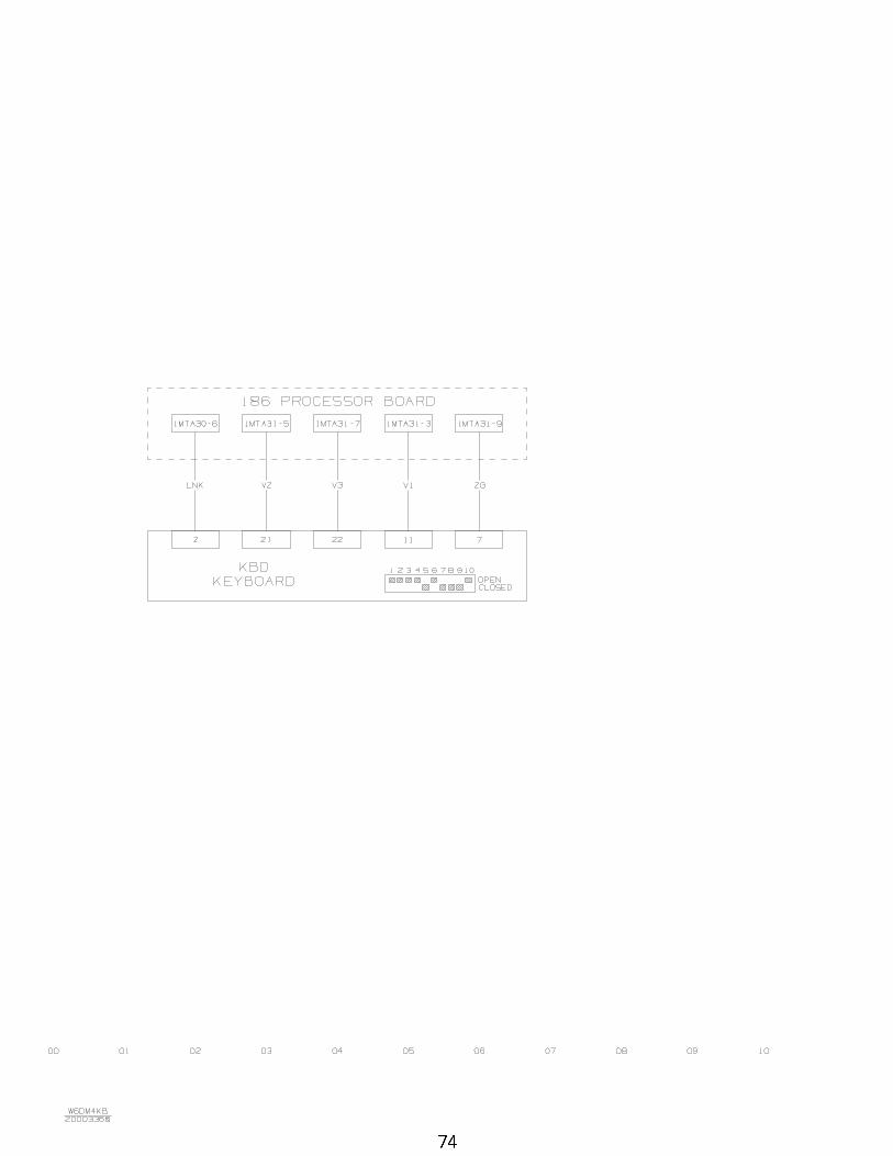
74 Keyboard Wiring W6DM4KB/2000336B
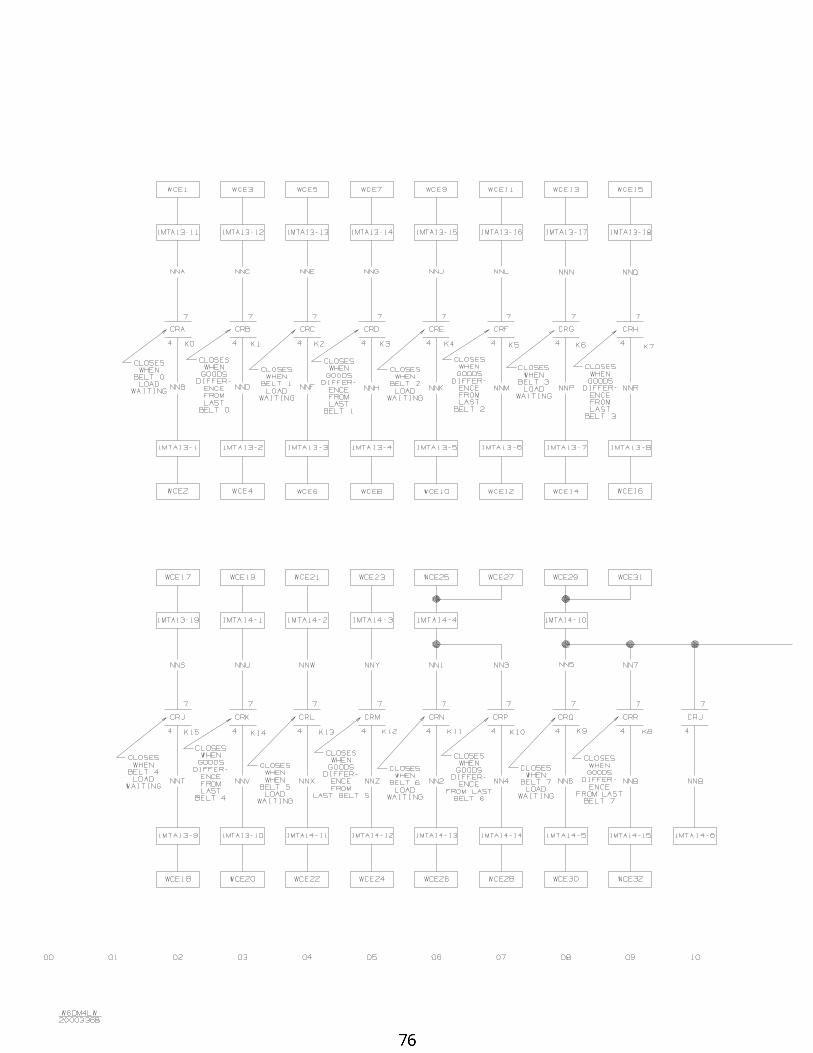
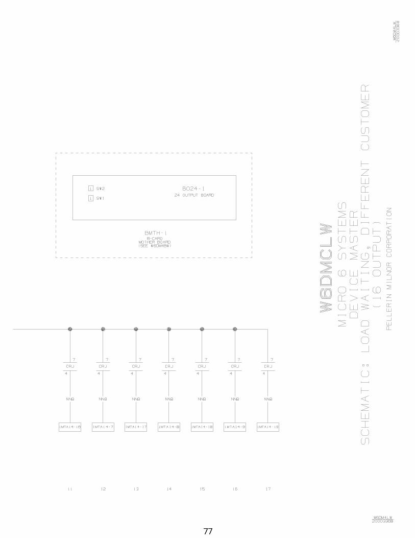
76 Load Waiting - Different Customer W6DM4LW/2000336B
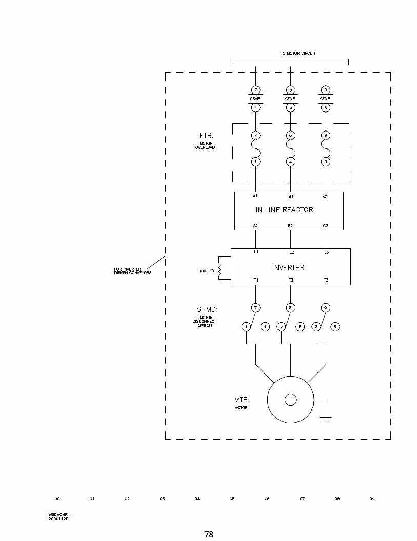
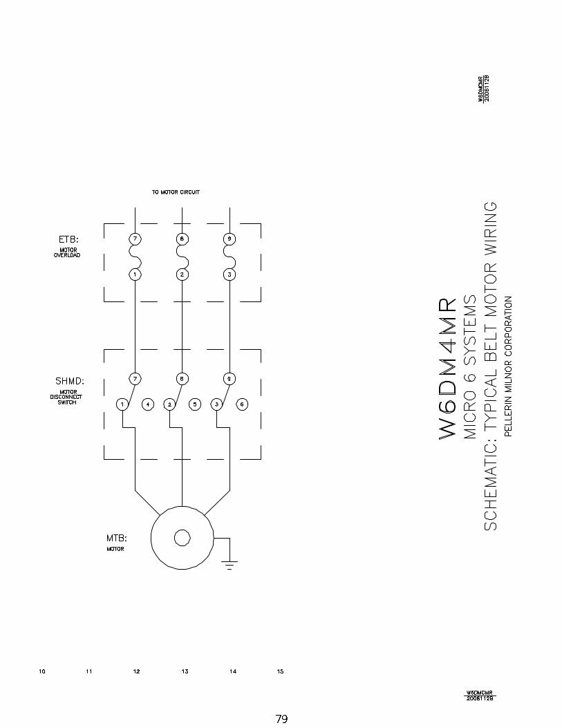
78 Typical Belt Motor Wiring W6DM4MR/2006112B
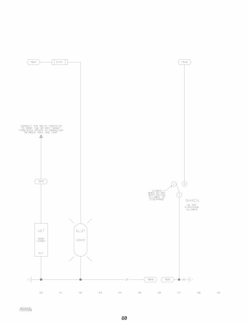
80 No - Dry Destination W6DM4ND/2000336B
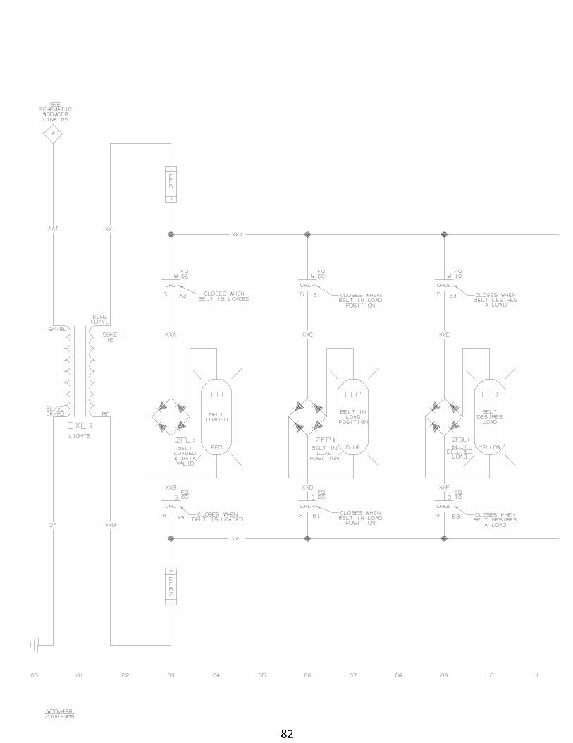
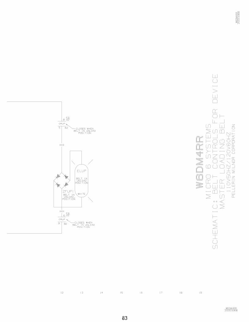
82 Loading Belt Lights W6DM4RR/2000336B
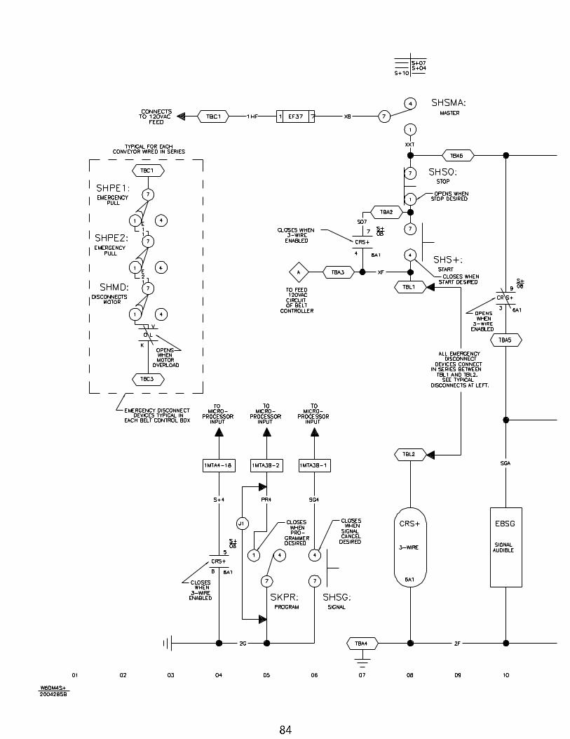
84 Start Circuit W6DM4S+/2004285B
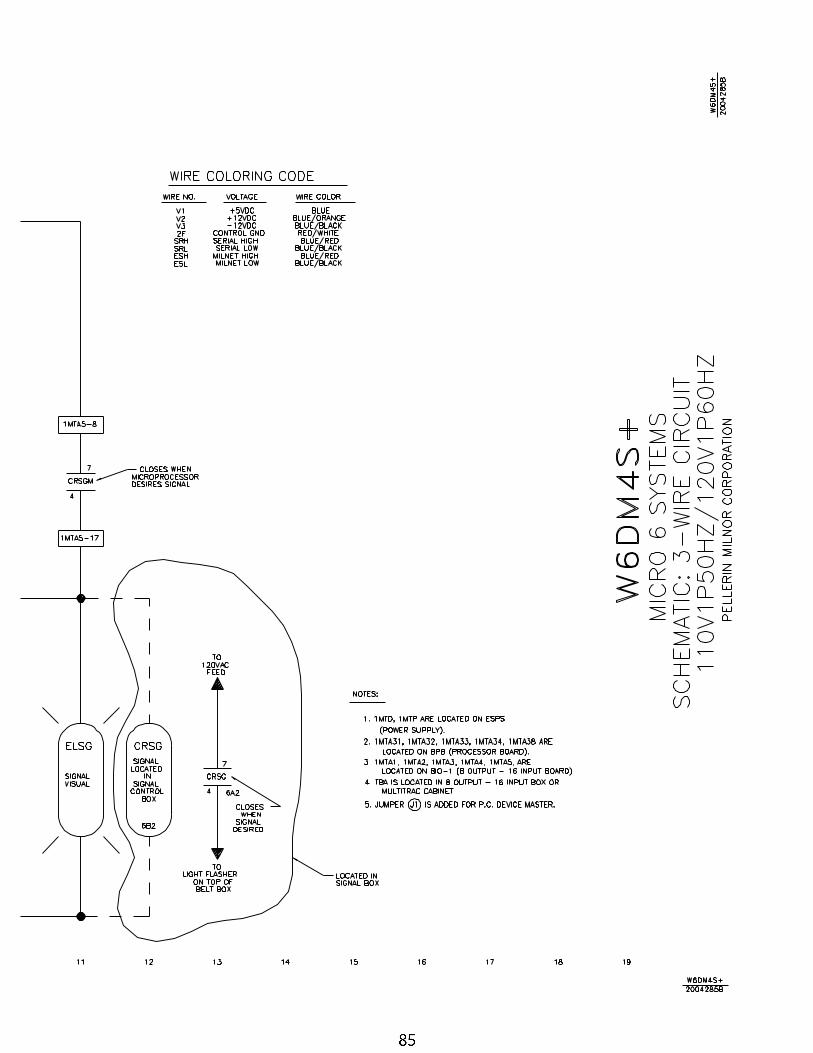
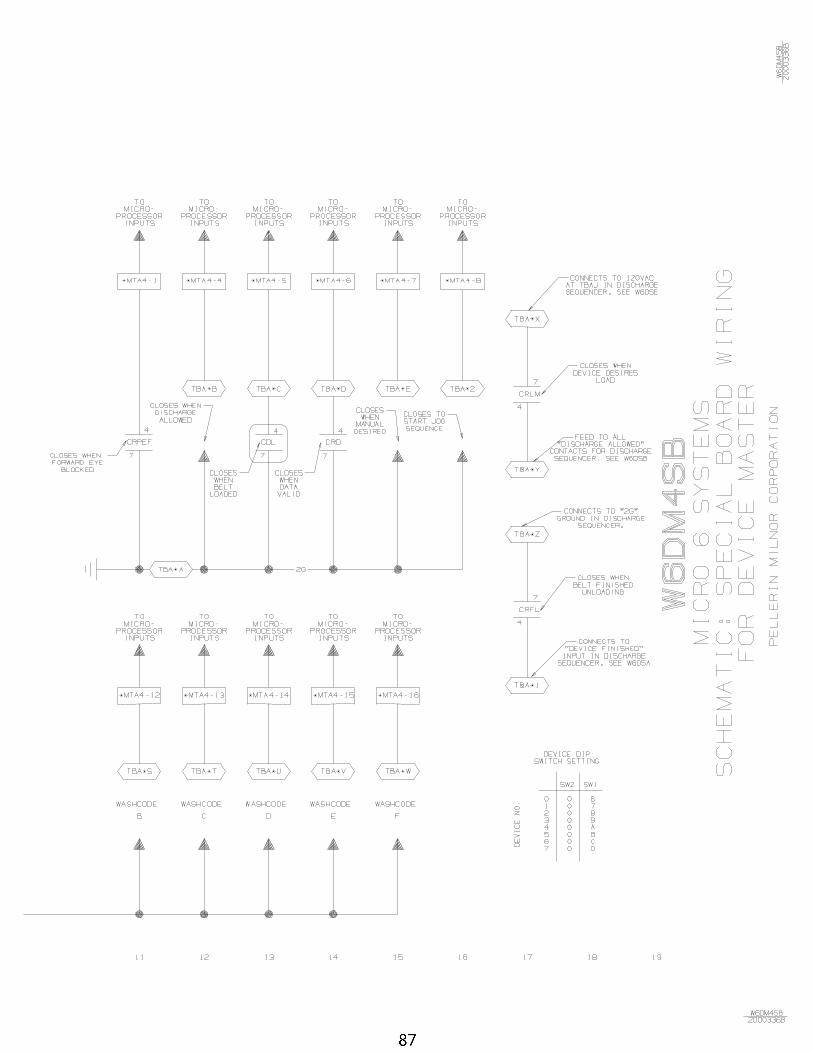
86 Special Board Wiring W6DM4SB/2000336B
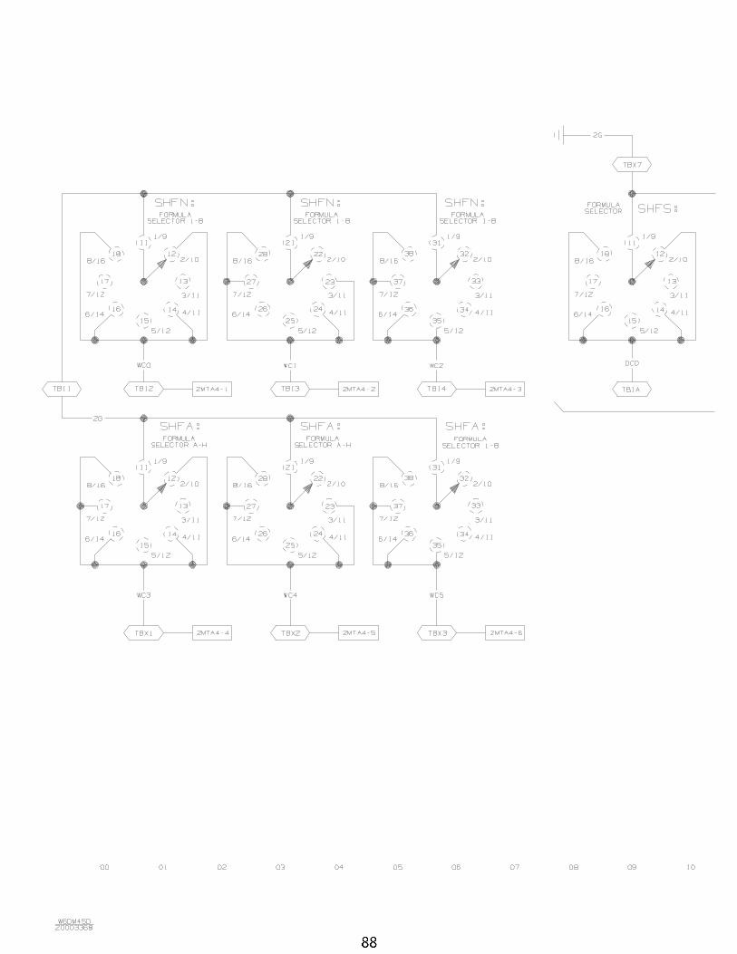
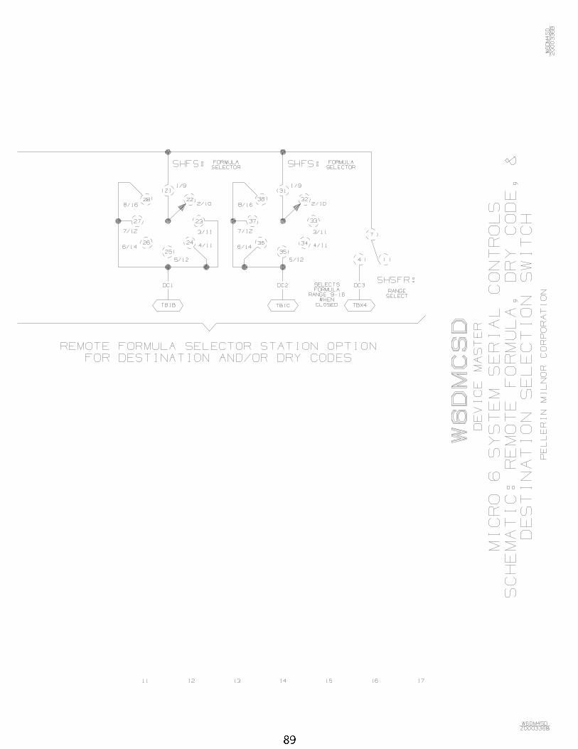
88 Rormulas, Dry Codes, and Destination Codes W6DM4SD/2000336B

Table of Contents, cont.Page Description Document/ECN
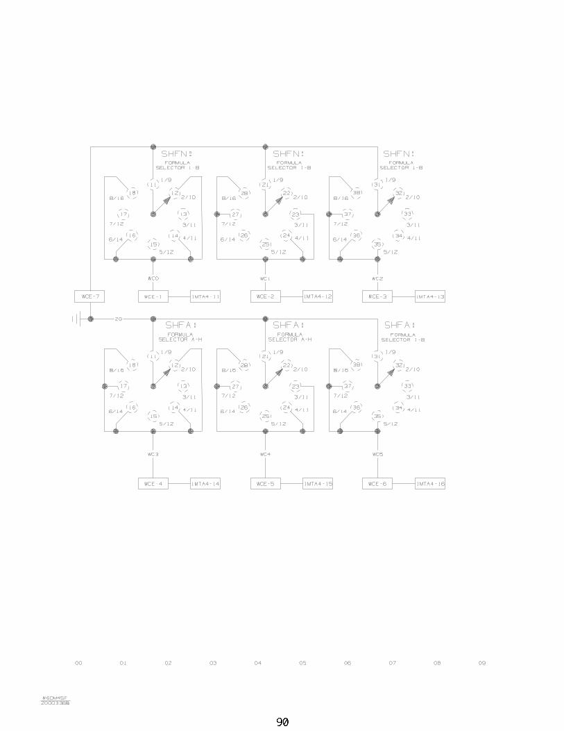
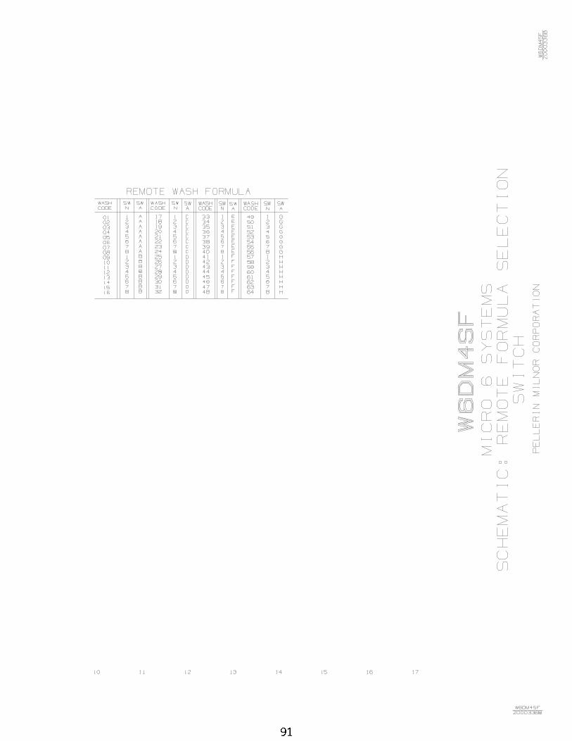
90 Remote Formula Select Switch W6DM4SF/2000336B
C O
M P
O N
E N
T
P A
R T
S
L I
S T
W
6DM
4PL/
2001
233N
CO
MP
ON
EN
TF
UN
CT
ION
OF
WH
ER
E T
O F
IND
NU
MB
ER
TH
IS C
OM
PO
NE
NT
TH
IS C
OM
PO
NE
NT
MIL
NO
R P
/ND
ES
CR
IPT
ION
LO
CA
TIO
N
BA
>>P
RIN
TE
D C
IRC
UIT
BO
AR
DS
BB
B-1
BO
AR
D-M
EM
OR
Y B
AT
TE
RY
BA
CK
UP
W6D
M4B
W08
BS
BB
1TB
OA
RD
: SE
R B
AT
T B
AC
KU
P-T
ES
TC
ON
TR
OLL
ER
BX
BIO
-1B
OA
RD
-8O
UT
PU
T/1
6IN
PU
T #
1W
6DM
4BW
08B
S81
6CT
BD
:SE
RIA
L 8O
UT
-16I
NP
UT
-TE
ST
BO
AR
D B
OX
BIO
-16
BO
AR
D-8
OU
TP
UT
/16I
NP
UT
W
6DM
4EB
08B
SO
24A
TB
D:S
ER
IAL
24 O
UT
PU
T->
TE
ST
CO
NT
RO
LLE
R B
X
BIO
-2B
OA
RD
-8O
UT
PU
T/1
6IN
PU
T #
2W
6DM
4BW
08B
S81
6CT
BD
:SE
RIA
L 8O
UT
-16I
NP
UT
-TE
ST
BO
AR
D B
OX
BIO
-5B
OA
RD
-8O
UT
PU
T/1
6IN
PU
T #
3W
6DM
4FD
08B
S81
6CT
BD
:SE
RIA
L 8O
UT
-16I
NP
UT
-TE
ST
CO
NT
RO
LLE
R B
X
BO
24-1
BO
AR
D-2
4 O
UT
PU
T B
OA
RD
W6D
M4L
W08
BS
O24
AT
BD
:SE
RIA
L 24
OU
TP
UT
->T
ES
TB
OA
RD
BO
X
BO
24-1
0B
OA
RD
-24
OU
TP
UT
DE
VIC
E F
INIS
HE
D D
ISC
HW
6DM
4DF
08B
SO
24A
TB
D:S
ER
IAL
24 O
UT
PU
T->
TE
ST
BO
AR
D B
OX
BO
24-2
BO
AR
D-2
4 O
UT
PU
T D
AT
A P
AS
SW
6DM
4DP
08B
SO
24A
TB
D:S
ER
IAL
24 O
UT
PU
T->
TE
ST
BO
AR
D B
OX
BP
BB
OA
RD
-186
MIC
RO
PR
OC
ES
SO
RW
6DM
4BW
08B
SP
E1T
186
SE
R P
RO
C-T
ES
TC
ON
TR
OLL
ER
BX
BV
GA
BO
AR
D-V
GA
VID
EO
CO
NT
RO
LLE
RW
6DM
4BW
08P
CV
GA
16S
VG
A B
D 1
024X
768N
I 512
K IS
AC
ON
TR
OLL
ER
BX
CD
>>R
EL
AY
-TIM
E D
EL
AY
CD
1D
ELA
Y-D
EV
ICE
AC
CE
PT
S L
OA
DW
6DM
4AD
09C
F01
6037
TD
R F
16S
2P
DT
11P
IN 1
20V
50/6
0CB
ELT
CN
TL
BO
X
CD
CH
PD
ELA
Y-C
OH
OR
P L
OA
DE
DW
6DM
4CH
A09
CF
0020
37T
DR
F2S
2P
DT
11P
IN 1
20V
60/5
0CO
N C
OH
OR
P
CD
LD
ELA
Y-B
ELT
LO
AD
ED
W6D
M4S
B09
CF
0020
37T
DR
F2S
2P
DT
11P
IN 1
20V
60/5
0CC
ON
TR
OLL
ER
BX
CLL
LAT
CH
-BE
LT D
ES
IRE
S L
OA
DW
6DM
4AD
09C
L2C
-C37
RE
LAY
-LA
TC
H D
PD
T 1
20V
2-C
OIL
BE
LT C
NT
L B
OX
CP
>>P
HO
TO
EY
ES
CP
CH
PP
HO
TO
EY
E-C
OH
OR
P L
OA
DE
DW
6DM
4CH
A09
RP
E00
4S
EN
SO
R D
AR
K O
PE
RA
TE
AC
N/O
-OU
TO
N C
OH
OR
P
CP
PE
FP
HO
TO
EY
E-D
ISC
HA
RG
E E
ND
OF
BE
LTW
6DM
4FP
09R
PE
004
SE
NS
OR
DA
RK
OP
ER
AT
E A
C N
/O-O
UT
ON
CO
HO
RP
CP
PE
FP
HO
TO
EY
E-F
OR
WA
RD
W6D
M4S
B09
RP
E00
4S
EN
SO
R D
AR
K O
PE
RA
TE
AC
N/O
-OU
TO
N C
OH
OR
P
CP
PE
F0
PH
OT
OE
YE
-BE
LT 0
FO
RW
AR
DW
6DM
4FR
009
RP
E01
1P
HO
TO
EY
E V
ALU
-BE
AM
10-
30D
CE
ND
OF
BE
LT
CP
PE
F0
PH
OT
OE
YE
-BE
LT 0
FO
RW
AR
DW
6DM
4CH
09
RP
E01
1P
HO
TO
EY
E V
ALU
-BE
AM
10-
30D
CE
ND
OF
BE
LT
CP
PE
F1
PH
OT
OE
YE
-BE
LT 1
FO
RW
AR
DW
6DM
4FR
109
RP
E01
1P
HO
TO
EY
E V
ALU
-BE
AM
10-
30D
CE
ND
OF
BE
LT
CP
PE
F2
PH
OT
OE
YE
-BE
LT 2
FO
RW
AR
DW
6DM
4FR
209
RP
E01
1P
HO
TO
EY
E V
ALU
-BE
AM
10-
30D
CE
ND
OF
BE
LT
CP
PE
F3
PH
OT
OE
YE
-BE
LT 3
FO
RW
AR
DW
6DM
4FR
309
RP
E01
1P
HO
TO
EY
E V
ALU
-BE
AM
10-
30D
CE
ND
OF
BE
LT
CP
PE
F4
PH
OT
OE
YE
-BE
LT 4
FO
RW
AR
DW
6DM
4FR
409
RP
E01
1P
HO
TO
EY
E V
ALU
-BE
AM
10-
30D
CE
ND
OF
BE
LT
CP
PE
F5
PH
OT
OE
YE
-BE
LT 5
FO
RW
AR
DW
6DM
4FR
509
RP
E01
1P
HO
TO
EY
E V
ALU
-BE
AM
10-
30D
CE
ND
OF
BE
LT
CP
PE
F6
PH
OT
OE
YE
-BE
LT 6
FO
RW
AR
DW
6DM
4FR
609
RP
E01
1P
HO
TO
EY
E V
ALU
-BE
AM
10-
30D
CE
ND
OF
BE
LT
CP
PE
F7
PH
OT
OE
YE
-BE
LT 7
FO
RW
AR
DW
6DM
4FR
709
RP
E01
1P
HO
TO
EY
E V
ALU
-BE
AM
10-
30D
CE
ND
OF
BE
LT
CP
PE
R0
PH
OT
OE
YE
-BE
LT 0
RE
VE
RS
EW
6DM
4FR
009
RP
E01
1P
HO
TO
EY
E V
ALU
-BE
AM
10-
30D
CE
ND
OF
BE
LT
CP
PE
R0
PH
OT
OE
YE
-BE
LT 0
RE
VE
RS
EW
6DM
4CH
09
RP
E01
1P
HO
TO
EY
E V
ALU
-BE
AM
10-
30D
CE
ND
OF
BE
LT
CP
PE
R1
PH
OT
OE
YE
-BE
LT 1
RE
VE
RS
EW
6DM
4FR
109
RP
E01
1P
HO
TO
EY
E V
ALU
-BE
AM
10-
30D
CE
ND
OF
BE
LT
CP
PE
R2
PH
OT
OE
YE
-BE
LT 2
RE
VE
RS
EW
6DM
4FR
209
RP
E01
1P
HO
TO
EY
E V
ALU
-BE
AM
10-
30D
CE
ND
OF
BE
LT
Pag
e 1
of 7
C O
M P
O N
E N
T
P A
R T
S
L I
S T
W
6DM
4PL/
2001
233N
CO
MP
ON
EN
TF
UN
CT
ION
OF
WH
ER
E T
O F
IND
NU
MB
ER
TH
IS C
OM
PO
NE
NT
TH
IS C
OM
PO
NE
NT
MIL
NO
R P
/ND
ES
CR
IPT
ION
LO
CA
TIO
N
CP
PE
R3
PH
OT
OE
YE
-BE
LT 3
RE
VE
RS
EW
6DM
4FR
309
RP
E01
1P
HO
TO
EY
E V
ALU
-BE
AM
10-
30D
CE
ND
OF
BE
LT
CP
PE
R4
PH
OT
OE
YE
-BE
LT 4
RE
VE
RS
EW
6DM
4FR
409
RP
E01
1P
HO
TO
EY
E V
ALU
-BE
AM
10-
30D
CE
ND
OF
BE
LT
CP
PE
R5
PH
OT
OE
YE
-BE
LT 5
RE
VE
RS
EW
6DM
4FR
509
RP
E01
1P
HO
TO
EY
E V
ALU
-BE
AM
10-
30D
CE
ND
OF
BE
LT
CP
PE
R6
PH
OT
OE
YE
-BE
LT 6
RE
VE
RS
EW
6DM
4FR
609
RP
E01
1P
HO
TO
EY
E V
ALU
-BE
AM
10-
30D
CE
ND
OF
BE
LT
CP
PE
R7
PH
OT
OE
YE
-BE
LT 7
RE
VE
RS
EW
6DM
4FR
709
RP
E01
1P
HO
TO
EY
E V
ALU
-BE
AM
10-
30D
CE
ND
OF
BE
LT
CP
PS
B5
PH
OT
OE
YE
-FE
ED
ER
BE
LT #
5W
6DM
4FS
509
RP
E01
1P
HO
TO
EY
E V
ALU
-BE
AM
10-
30D
CF
EE
DE
R B
ELT
CP
PS
B6
PH
OT
OE
YE
-FE
ED
ER
BE
LT #
6W
6DM
4FS
609
RP
E01
1P
HO
TO
EY
E V
ALU
-BE
AM
10-
30D
CF
EE
DE
R B
ELT
CP
RD
PH
OT
OE
YE
-DIS
CH
AR
GE
EN
DW
6DM
4AD
09R
PE
004
SE
NS
OR
DK
.OP
R.A
C N
/O-O
UT
SID
E O
F B
ELT
CR
>>R
EL
AY
-PIL
OT
OR
CO
NT
RO
L
CR
DR
ELA
Y-D
AT
A V
ALI
D B
ELT
LO
AD
ED
W6D
M4F
Q09
C02
4D37
4PD
T "
KH
" 11
0/12
0VB
ELT
CO
NT
RO
LR
CR
DR
ELA
Y-D
AT
A V
ALI
D
W6D
M4S
B09
C02
4D37
4PD
T "
KH
" 11
0/12
0VC
ON
TR
OLL
ER
BX
CR
DR
ELA
Y-D
ISC
HA
RG
E E
ND
BLO
CK
ED
W6D
M4A
D09
C01
DD
D37
RE
LAY
-3P
DT
DIF
GO
LD 1
1PIN
120
VA
CB
ELT
CN
TL
BO
X
CR
D
RE
LAY
-CO
HO
RP
AT
DIS
CH
RG
EW
6DM
4CH
A09
C02
4D37
4PD
T "
KH
" 11
0/12
0VO
N C
OH
OR
P
CR
DL
RE
LAY
-BE
LT D
ES
IRE
S L
OA
DW
6DM
4FQ
09C
024D
374P
DT
"K
H"
110/
120V
BE
LT C
ON
TR
OLR
CR
DS
RE
LAY
-DA
TA
VA
LID
BE
LT L
OA
DE
DW
6DM
4FQ
09C
024D
374P
DT
"K
H"
110/
120V
BE
LT C
ON
TR
OLR
CR
FL
RE
LAY
-BE
LT F
INIS
HE
D U
NLO
AD
ING
W6D
M4S
B09
C02
4D37
4PD
T "
KH
" 11
0/12
0VC
ON
TR
OLL
ER
BX
CR
H
RE
LAY
-CO
HO
RP
AT
HO
ME
W6D
M4C
HA
09C
024D
374P
DT
"K
H"
110/
120V
ON
CO
HO
RP
CR
L R
ELA
Y-B
ELT
IS L
OA
DE
DW
6DM
4FQ
09C
024D
374P
DT
"K
H"
110/
120V
BE
LT C
ON
TR
OLR
CR
LLS
RE
LAY
-BE
LT IS
LO
AD
ED
W6D
M4F
Q09
C02
4D37
4PD
T "
KH
" 11
0/12
0VB
ELT
CO
NT
RO
LR
CR
LMR
ELA
Y-D
ES
IRE
S L
OA
DW
6DM
4FQ
09C
024D
374P
DT
"K
H"
110/
120V
CO
NT
RO
LLE
R B
X
CR
LPR
ELA
Y-B
ELT
IN L
OA
D P
OS
ITIO
NW
6DM
4FQ
09C
024D
374P
DT
"K
H"
110/
120V
BE
LT C
ON
TR
OLR
CR
MR
ELA
Y-M
AN
UA
L E
NA
BLE
W6D
M4F
Q09
C02
4D37
4PD
T "
KH
" 11
0/12
0VB
ELT
CO
NT
RO
LR
CR
MS
RE
LAY
-MA
NU
AL
EN
AB
LEW
6DM
4FQ
09C
024D
374P
DT
"K
H"
110/
120V
BE
LT C
ON
TR
OLR
CR
PE
FR
ELA
Y-D
ISC
HA
RG
E E
ND
OF
BE
LTW
6DM
4FP
09C
024D
374P
DT
"K
H"
110/
120V
BE
LT C
ON
TR
OLR
CR
PE
FR
ELA
Y-F
OR
WA
RD
PH
OT
OE
YE
W6D
M4S
B09
C02
4D37
4PD
T "
KH
" 11
0/12
0VC
ON
TR
OLL
ER
BX
CR
RB
F0
RE
LAY
-RU
N B
ELT
0 F
OR
WA
RD
W6D
M4C
H09
C02
4D37
4PD
T "
KH
" 11
0/12
0VB
ELT
CO
NT
RO
LR
CR
S+
RE
LAY
-3-W
IRE
W6D
M4F
Q09
C02
4D37
4PD
T "
KH
" 11
0/12
0VB
ELT
CO
NT
RO
LR
CR
S+
RE
LAY
-3-W
IRE
W6D
M4S
+09
C02
4D37
4PD
T "
KH
" 11
0/12
0VB
ELT
CO
NT
RO
LR
CR
S+
RE
LAY
-3-W
IRE
W
6DM
4AD
09C
01D
DD
37R
ELA
Y-3
PD
T D
IFG
OLD
11P
IN 1
20V
AC
BE
LT C
NT
L B
OX
CR
SB
5R
ELA
Y-F
EE
DE
R B
ELT
#5
BLO
CK
ED
W6D
M4F
S5
09C
024D
374P
DT
"K
H"
110/
120V
FE
ED
ER
BE
LT
CR
SB
6R
ELA
Y-F
EE
DE
R B
ELT
#6
BLO
CK
ED
W6D
M4F
S6
09C
024D
374P
DT
"K
H"
110/
120V
FE
ED
ER
BE
LT
CR
SG
RE
LAY
-SIG
NA
LW
6DM
4S+
09C
024D
374P
DT
"K
H"
110/
120V
CO
NT
RO
LLE
R B
X
CR
T>>
EL
EC
TR
ON
IC M
ON
ITO
RS
Pag
e 2
of 7
C O
M P
O N
E N
T
P A
R T
S
L I
S T
W
6DM
4PL/
2001
233N
CO
MP
ON
EN
TF
UN
CT
ION
OF
WH
ER
E T
O F
IND
NU
MB
ER
TH
IS C
OM
PO
NE
NT
TH
IS C
OM
PO
NE
NT
MIL
NO
R P
/ND
ES
CR
IPT
ION
LO
CA
TIO
N
CR
T-1
MO
NIT
OR
-MIC
RO
PR
OC
ES
SO
RW
6DM
4BW
08M
N07
0VG
AM
ON
ITO
R S
VG
A 1
4" .2
8DP
NI
MO
NIT
OR
BO
X
CR
UP
RE
LAY
-BE
LT IN
UN
LOA
D P
OS
ITIO
NW
6DM
4FQ
09C
01D
DD
37R
ELA
Y 3
PD
T D
IFG
OLD
11P
IN 1
20V
AC
BE
LT C
ON
TR
OLR
CS
>>C
ON
TA
CT
OR
-MO
TO
R S
TA
RT
ER
CS
BF
CO
NT
AC
TO
R-B
ELT
FO
RW
AR
DW
6DM
4AD
09M
R08
B33
712
A 3
P R
EV
+2N
/C 1
20V
5/6
IEC
CO
NT
AC
T B
OX
CS
BR
CO
NT
AC
TO
R-B
ELT
RE
VE
RS
EW
6DM
4AD
09M
R08
B33
712
A 3
P R
EV
+2N
/C 1
20V
5/6
IEC
CO
NT
AC
T B
OX
CS
RB
FC
ON
TA
CT
OR
-RU
N L
OA
DIN
G B
ELT
W6D
M4F
P09
MR
08B
337
12A
3P
RE
V+
2N/C
120
V5/
6 IE
CC
ON
TA
CT
OR
BX
CS
RB
FC
ON
TA
CT
OR
-RU
N F
OR
WA
RD
W6D
M4S
B09
MR
08B
337
12A
3P
RE
V+
2N/C
120
V5/
6 IE
CC
ON
TA
CT
OR
BX
CS
RB
F0
CO
NT
AC
TO
R-R
UN
BE
LT 0
FO
RW
AR
DW
6DM
4RF
009
MR
08B
337
12A
3P
RE
V+
2N/C
120
V5/
6 IE
CC
ON
TA
CT
OR
BX
CS
RB
F0
CO
NT
AC
TO
R-R
UN
BE
LT F
OR
WA
RD
W6D
M4C
H09
MR
08B
337
12A
3P
RE
V+
2N/C
120
V5/
6 IE
CC
ON
TA
CT
OR
BX
CS
RB
F1
CO
NT
AC
TO
R-R
UN
BE
LT 1
FO
RW
AR
DW
6DM
4RF
109
MR
08B
337
12A
3P
RE
V+
2N/C
120
V5/
6 IE
CC
ON
TA
CT
OR
BX
CS
RB
F2
CO
NT
AC
TO
R-R
UN
BE
LT 2
FO
RW
AR
DW
6DM
4RF
209
MR
08B
337
12A
3P
RE
V+
2N/C
120
V5/
6 IE
CC
ON
TA
CT
OR
BX
CS
RB
F3
CO
NT
AC
TO
R-R
UN
BE
LT 3
FO
RW
AR
DW
6DM
4RF
309
MR
08B
337
12A
3P
RE
V+
2N/C
120
V5/
6 IE
CC
ON
TA
CT
OR
BX
CS
RB
F4
CO
NT
AC
TO
R-R
UN
BE
LT 4
FO
RW
AR
DW
6DM
4RF
409
MR
08B
337
12A
3P
RE
V+
2N/C
120
V5/
6 IE
CC
ON
TA
CT
OR
BX
CS
RB
F5
CO
NT
AC
TO
R-R
UN
BE
LT 5
FO
RW
AR
DW
6DM
4RF
509
MR
08B
337
12A
3P
RE
V+
2N/C
120
V5/
6 IE
CC
ON
TA
CT
OR
BX
CS
RB
F6
CO
NT
AC
TO
R-R
UN
BE
LT 6
FO
RW
AR
DW
6DM
4RF
609
MR
08B
337
12A
3P
RE
V+
2N/C
120
V5/
6 IE
CC
ON
TA
CT
OR
BX
CS
RB
F7
CO
NT
AC
TO
R-R
UN
BE
LT 7
FO
RW
AR
DW
6DM
4RF
709
MR
08B
337
12A
3P
RE
V+
2N/C
120
V5/
6 IE
CC
ON
TA
CT
OR
BX
CS
RB
RC
ON
TA
CT
OR
-RU
N L
OA
DIN
G B
ELT
W6D
M4F
P09
MR
08B
337
12A
3P
RE
V+
2N/C
120
V5/
6 IE
CC
ON
TA
CT
OR
BX
CS
RB
RC
ON
TA
CT
OR
-RU
N R
EV
ER
SE
W6D
M4S
B09
MR
08B
337
12A
3P
RE
V+
2N/C
120
V5/
6 IE
CC
ON
TA
CT
OR
BX
CS
RB
R0
CO
NT
AC
TO
R-R
UN
BE
LT 0
RE
VE
RS
EW
6DM
4RF
009
MR
08B
337
12A
3P
RE
V+
2N/C
120
V5/
6 IE
CC
ON
TA
CT
OR
BX
CS
RB
R0
CO
NT
AC
TO
R-R
UN
RE
VE
RS
EW
6DM
4CH
09M
R08
B33
712
A 3
P R
EV
+2N
/C 1
20V
5/6
IEC
CO
NT
AC
TO
R B
X
CS
RB
R1
CO
NT
AC
TO
R-R
UN
BE
LT 1
RE
VE
RS
EW
6DM
4RF
109
MR
08B
337
12A
3P
RE
V+
2N/C
120
V5/
6 IE
CC
ON
TA
CT
OR
BX
CS
RB
R2
CO
NT
AC
TO
R-R
UN
BE
LT 2
RE
VE
RS
EW
6DM
4RF
209
MR
08B
337
12A
3P
RE
V+
2N/C
120
V5/
6 IE
CC
ON
TA
CT
OR
BX
CS
RB
R3
CO
NT
AC
TO
R-R
UN
BE
LT 3
RE
VE
RS
EW
6DM
4RF
309
MR
08B
337
12A
3P
RE
V+
2N/C
120
V5/
6 IE
CC
ON
TA
CT
OR
BX
CS
RB
R4
CO
NT
AC
TO
R-R
UN
BE
LT 4
RE
VE
RS
EW
6DM
4RF
409
MR
08B
337
12A
3P
RE
V+
2N/C
120
V5/
6 IE
CC
ON
TA
CT
OR
BX
CS
RB
R5
CO
NT
AC
TO
R-R
UN
BE
LT 5
RE
VE
RS
EW
6DM
4RF
509
MR
08B
337
12A
3P
RE
V+
2N/C
120
V5/
6 IE
CC
ON
TA
CT
OR
BX
CS
RB
R6
CO
NT
AC
TO
R-R
UN
BE
LT 6
RE
VE
RS
EW
6DM
4RF
609
MR
08B
337
12A
3P
RE
V+
2N/C
120
V5/
6 IE
CC
ON
TA
CT
OR
BX
CS
RB
R7
CO
NT
AC
TO
R-R
UN
BE
LT 7
RE
VE
RS
EW
6DM
4RF
709
MR
08B
337
12A
3P
RE
V+
2N/C
120
V5/
6 IE
CC
ON
TA
CT
OR
BX
EB
>>B
UZ
ZE
R O
R A
UD
IBL
E S
IGN
AL
EB
CD
BU
ZZ
ER
-CO
HO
RP
MO
VIN
G T
O D
ISC
HA
RG
EW
6DM
4CH
A09
H02
0A
LAR
M S
ON
ALE
RT
115
VO
N C
OH
OR
P
EB
CH
BU
ZZ
ER
-CO
HO
RP
MO
VIN
G T
O H
OM
EW
6DM
4CH
A09
H02
0A
LAR
M S
ON
ALE
RT
115
VO
N C
OH
OR
P
EB
SG
BU
ZZ
ER
-SIG
NA
L A
UD
IBLE
W6D
M4F
Q09
H01
5B
UZ
ZE
R 1
15V
W/6
-32
CR
T+
6" L
EA
DS
BE
LT C
ON
TR
OLR
EB
SG
BU
ZZ
ER
-SIG
NA
L A
UD
IBLE
W6D
M4S
+09
H01
5B
UZ
ZE
R 1
15V
W/6
-32
CR
T+
6" L
EA
DS
CO
NT
RO
LLE
R B
X
EB
SG
BU
ZZ
ER
-SIG
NA
LW
6DM
4AD
09H
015
BU
ZZ
ER
115
V W
/6-3
2 C
RT
+6"
LE
AD
SB
ELT
CN
TL
BO
X
Pag
e 3
of 7
C O
M P
O N
E N
T
P A
R T
S
L I
S T
W
6DM
4PL/
2001
233N
CO
MP
ON
EN
TF
UN
CT
ION
OF
WH
ER
E T
O F
IND
NU
MB
ER
TH
IS C
OM
PO
NE
NT
TH
IS C
OM
PO
NE
NT
MIL
NO
R P
/ND
ES
CR
IPT
ION
LO
CA
TIO
N
EF
>>F
US
E O
R F
US
E H
OL
DE
R
EF
37F
US
E-1
20V
CO
NT
RO
L C
IRC
UIT
W6D
M4C
H09
FF
004A
HG
FU
SE
BK
/MD
X 4
AM
P 1
25V
BU
SS
BE
LT C
ON
TR
OLR
EF
37F
US
E-1
20V
CO
NT
RO
L C
IRC
UIT
W6D
M4F
R0
09F
F00
4AH
GF
US
E B
K/M
DX
4 A
MP
125
V B
US
SB
ELT
CO
NT
RO
LR
EF
37F
US
E-1
20V
CO
NT
RO
L C
IRC
UIT
W6D
M4N
D09
FF
002A
MG
FU
SE
BK
/MD
X 2
AM
P 2
50V
BU
SS
NO
-DR
Y C
-BO
X
EF
C
>>F
LA
SH
ER
EF
CD
FLA
SH
ER
-CO
HO
RP
MO
VIN
G T
O D
ISC
HA
RG
EW
6DM
4CH
A08
FL0
0753
7F
LAS
HE
R 1
20V
1 A
MP
75F
FL/
MIN
ON
CO
HO
RP
EF
CH
FLA
SH
ER
-CO
HO
RP
MO
VIN
G T
O H
OM
EW
6DM
4CH
A08
FL0
0753
7F
LAS
HE
R 1
20V
1 A
MP
75F
FL/
MIN
ON
CO
HO
RP
EL
>>L
IGH
T-P
ILO
T O
R IN
DIC
AT
OR
EL0
LIG
HT
-120
V A
VA
ILIB
LEW
6DM
4FR
009
J060
G37
LAM
P 1
/2"
GR
N 1
25V
IDI 1
052Q
C5
BE
LT C
ON
TR
OLR
EL0
LIG
HT
-120
V A
VA
ILIB
LEW
6DM
4CH
09J0
60A
37LA
MP
1/2
" A
MB
125
V ID
I 105
0QC
3B
ELT
CO
NT
RO
LR
EL3
7LI
GH
T-1
20V
AV
AIL
IBLE
W6D
M4N
D09
J060
A37
LAM
P 1
/2"
AM
B 1
25V
IDI 1
050Q
C3
NO
-DR
Y C
-BO
X
ELD
LI
GH
T-B
ELT
DE
SIR
ES
LO
AD
W6D
M4R
R09
J070
RE
CLI
TE
-ST
OP
4"
RE
D L
EN
SB
ELT
LIG
HT
BX
ELL
LLI
GH
T-B
ELT
LO
AD
ED
W6D
M4R
R09
J070
RE
CLI
TE
-ST
OP
4"
RE
D L
EN
SB
ELT
LIG
HT
BX
ELP
LIG
HT
-BE
LT IN
LO
AD
PO
SIT
ION
W6D
M4R
R09
J070
RE
CLI
TE
-ST
OP
4"
RE
D L
EN
SB
ELT
LIG
HT
BX
ELS
+LI
GH
T-3
-WIR
EW
6DM
4FQ
09J0
60G
37LA
MP
1/2
" G
RN
125
V ID
I 105
2QC
5B
ELT
CO
NT
RO
LR
ELS
+LI
GH
T-3
-WIR
EW
6DM
4AD
09J0
60G
37LA
MP
1/2
" G
RN
125
V ID
I 105
0QC
3B
ELT
CN
TL
BO
X
ELS
GLI
GH
T-S
IGN
AL
W
6DM
4S+
09J0
60W
H37
LAM
P 1
/2"
WH
ITE
120
V T
AB
BE
LT C
ON
TR
OLR
ELU
PLI
GH
T-B
ELT
IN U
NLO
AD
PO
SIT
ION
W6D
M4R
R09
J070
RE
CLI
TE
-ST
OP
4"
RE
D L
EN
SB
ELT
LIG
HT
BX
ES
>>P
OW
ER
SU
PP
LY
-EL
EC
TR
ON
IC
ES
PS
PO
WE
R S
UP
PLY
-MIC
RO
PR
OC
ES
SO
RW
6DM
4BW
08P
SS
3401
T40
WA
TT
PO
WE
R S
UP
PLY
TE
ST
ED
CO
NT
RO
LLE
R B
X
ES
PS
3P
OW
ER
SU
PP
LY-P
HO
TO
EY
EW
6DM
4BW
08P
SL1
B22
4P
WR
SU
P 1
00-2
40V
AC
TO
24V
DC
CO
NT
RO
LLE
R B
X
ET
>>>T
HE
RM
AL
OV
ER
LO
AD
S
ET
BO
VE
RLO
AD
-BE
LT M
OT
OR
W6D
M4M
R09
FT
C00
10T
OL
RE
LAY
1.0
-2.9
A A
B#1
93-A
3D1
CO
NT
AC
TO
R B
X
EX
>>T
RA
NS
FO
RM
ER
S
EX
LT
RA
NS
FO
RM
ER
-LO
AD
ING
LIG
HT
SW
6DM
4RR
09U
002E
BR
XF
MR
120
/240
PR
I EB
R 1
2VD
CB
ELT
CO
NT
RO
LR
KB
>>K
EY
BO
AR
D-E
LE
CT
RO
NIC
KB
DK
EY
PA
D-M
ICR
OP
RO
CE
SS
OR
W6D
M4K
BE
C61
KP
BB
AS
SY
:ALP
HA
-NU
M B
ELT
BX
KE
YP
DK
EY
BO
AR
D B
X
MR
>>M
OT
OR
S
MT
BM
OT
OR
W6D
M4M
RM
ES
SA
GE
SO
SE
E S
PE
CIF
IC C
OM
PO
NE
NT
+N
AM
EP
LAT
ES
IDE
OF
BE
LT
SH
>>S
WIT
CH
-HA
ND
OP
ER
AT
ED
SH
AD
SW
ITC
H-B
ELT
ALL
OW
ED
TO
DIS
CH
AR
GE
W6D
M4F
P09
N40
5M21
0S
WA
SS
M2W
1N
OR
EM
OT
E IN
PU
T
SH
AD
SW
ITC
H-B
ELT
0 A
LLO
WE
D T
O D
ISC
HA
RG
EW
6DM
4FR
009
N40
5M21
0S
WA
SS
M2W
1N
OB
ELT
CO
NT
RO
LR
SH
AD
SW
ITC
H-B
ELT
1 A
LLO
WE
D T
O D
ISC
HA
RG
EW
6DM
4FR
109
N40
5M21
0S
WA
SS
M2W
1N
OB
ELT
CO
NT
RO
LR
Pag
e 4
of 7
C O
M P
O N
E N
T
P A
R T
S
L I
S T
W
6DM
4PL/
2001
233N
CO
MP
ON
EN
TF
UN
CT
ION
OF
WH
ER
E T
O F
IND
NU
MB
ER
TH
IS C
OM
PO
NE
NT
TH
IS C
OM
PO
NE
NT
MIL
NO
R P
/ND
ES
CR
IPT
ION
LO
CA
TIO
N
SH
AD
SW
ITC
H-B
ELT
2 A
LLO
WE
D T
O D
ISC
HA
RG
EW
6DM
4FR
209
N40
5M21
0S
WA
SS
M2W
1N
OB
ELT
CO
NT
RO
LR
SH
AD
SW
ITC
H-B
ELT
3 A
LLO
WE
D T
O D
ISC
HA
RG
EW
6DM
4FR
309
N40
5M21
0S
WA
SS
M2W
1N
OB
ELT
CO
NT
RO
LR
SH
AD
SW
ITC
H-B
ELT
4 A
LLO
WE
D T
O D
ISC
HA
RG
EW
6DM
4FR
409
N40
5M21
0S
WA
SS
M2W
1N
OB
ELT
CO
NT
RO
LR
SH
AD
SW
ITC
H-B
ELT
5 A
LLO
WE
D T
O D
ISC
HA
RG
EW
6DM
4FR
509
N40
5M21
0S
WA
SS
M2W
1N
OB
ELT
CO
NT
RO
LR
SH
AD
SW
ITC
H-B
ELT
6 A
LLO
WE
D T
O D
ISC
HA
RG
EW
6DM
4FR
609
N40
5M21
0S
WA
SS
M2W
1N
OB
ELT
CO
NT
RO
LR
SH
AD
SW
ITC
H-B
ELT
7 A
LLO
WE
D T
O D
ISC
HA
RG
EW
6DM
4FR
709
N40
5M21
0S
WA
SS
M2W
1N
OB
ELT
CO
NT
RO
LR
SH
AD
SW
ITC
H-D
ISC
HA
RG
E A
LLO
WE
DW
6DM
4I09
N40
5M21
0S
WA
SS
M2W
1N
OB
ELT
CO
NT
RO
LR
SH
AD
SW
ITC
H-D
ISC
HA
RG
E A
LLO
WE
DW
6DM
4ND
09N
405M
210
SW
AS
S M
2W 1
NO
BE
LT C
ON
TR
OLR
SH
AL
SW
ITC
H-L
OA
D A
LLO
WE
DW
6DM
4I09
N40
5M21
0S
WA
SS
M2W
1N
OB
ELT
CO
NT
RO
LR
SH
AM
SW
ITC
H-A
UT
O/M
AN
UA
LW
6DM
4FQ
09N
405M
210
SW
AS
S M
2W 1
NO
BE
LT C
ON
TR
OLR
SH
AM
SW
ITC
H-A
UT
OM
AT
IC/M
AN
UA
LW
6DM
4AD
09N
400C
BN
OC
ON
TA
CT
BLK
ON
LY 1
-NO
SQ
D#Z
B2B
E10
1B
ELT
CN
TL
BO
X
SH
BA
LS
WIT
CH
-FE
ED
ER
BE
LT #
5 LD
ALL
OW
ED
W6D
M4F
S5
09N
405P
B10
SW
AS
S P
BB
K 1
NO
BE
LT C
ON
TR
OLR
SH
BA
LS
WIT
CH
-FE
ED
ER
BE
LT #
6 LD
ALL
OW
ED
W6D
M4F
S6
09N
405P
B10
SW
AS
S P
BB
K 1
NO
BE
LT C
ON
TR
OLR
SH
DS
WIT
CH
-DA
TA
VA
LID
-BE
LT L
OA
DE
DW
6DM
4FQ
09N
405P
B10
SW
AS
S P
BB
K 1
NO
BE
LT C
ON
TR
OLR
SH
DT
SW
ITC
H-B
ELT
0 A
LLO
WE
D T
O L
OA
DW
6DM
4FR
009
N40
5M21
0S
WA
SS
M2W
1N
OB
ELT
CO
NT
RO
LR
SH
DT
SW
ITC
H-B
ELT
1 A
LLO
WE
D T
O L
OA
DW
6DM
4FR
109
N40
5M21
0S
WA
SS
M2W
1N
OB
ELT
CO
NT
RO
LR
SH
DT
SW
ITC
H-B
ELT
2 A
LLO
WE
D T
O L
OA
DW
6DM
4FR
209
N40
5M21
0S
WA
SS
M2W
1N
OB
ELT
CO
NT
RO
LR
SH
DT
SW
ITC
H-B
ELT
3 A
LLO
WE
D T
O L
OA
DW
6DM
4FR
309
N40
5M21
0S
WA
SS
M2W
1N
OB
ELT
CO
NT
RO
LR
SH
DT
SW
ITC
H-B
ELT
4 A
LLO
WE
D T
O L
OA
DW
6DM
4FR
409
N40
5M21
0S
WA
SS
M2W
1N
OB
ELT
CO
NT
RO
LR
SH
DT
SW
ITC
H-B
ELT
5 A
LLO
WE
D T
O L
OA
DW
6DM
4FR
509
N40
5M21
0S
WA
SS
M2W
1N
OB
ELT
CO
NT
RO
LR
SH
DT
SW
ITC
H-B
ELT
6 A
LLO
WE
D T
O L
OA
DW
6DM
4FR
609
N40
5M21
0S
WA
SS
M2W
1N
OB
ELT
CO
NT
RO
LR
SH
DT
SW
ITC
H-B
ELT
7 A
LLO
WE
D T
O L
OA
DW
6DM
4FR
709
N40
5M21
0S
WA
SS
M2W
1N
OB
ELT
CO
NT
RO
LR
SH
FA
SW
ITC
H-R
EM
OT
E F
OR
MU
LA S
ELE
CT
ALP
HA
W6D
M4S
D09
N04
1NR
OT
SW
5-P
OLE
8-P
OS
IT 5
A12
5VR
M S
ELE
CT
BX
SH
FA
SW
ITC
H-R
EM
OT
E F
OR
MU
LA S
ELE
CT
ALP
HA
W6D
M4S
F09
N04
1NR
OT
SW
5-P
OLE
8-P
OS
IT 5
A12
5VF
OR
MU
LA S
ELC
T
SH
FN
SW
ITC
H-R
EM
OT
E F
OR
MU
LA S
ELE
CT
NU
MB
W6D
M4S
D09
N04
1NR
OT
SW
5-P
OLE
8-P
OS
IT 5
A12
5VR
M S
ELE
CT
BX
SH
FN
SW
ITC
H-R
EM
OT
E F
OR
MU
LA S
ELE
CT
NU
MB
W6D
M4S
F09
N04
1NR
OT
SW
5-P
OLE
8-P
OS
IT 5
A12
5VF
OR
MU
LA S
ELC
T
SH
FR
SW
ITC
H-F
OR
WA
RD
/RE
VE
RS
EW
6DM
4AD
09N
400C
BN
OC
ON
TA
CT
BLK
ON
LY 1
-NO
SQ
D#Z
B2B
E10
1B
ELT
CN
TL
BO
X
SH
FS
SW
ITC
H-R
EM
OT
E F
OR
MU
LA S
ELE
CT
0-1
5W
6DM
4SD
09N
041N
RO
TS
W 5
-PO
LE 8
-PO
SIT
5A
125V
RM
SE
LEC
T B
X
SH
JOG
SW
ITC
H-F
EE
DE
R B
ELT
#5
JOG
W6D
M4F
S5
09N
405P
B10
SW
AS
S P
BB
K 1
NO
FE
ED
ER
BLT
CN
T
SH
JOG
SW
ITC
H-F
EE
DE
R B
ELT
#6
JOG
W6D
M4F
S6
09N
405P
B10
SW
AS
S P
BB
K 1
NO
FE
ED
ER
BLT
CN
T
SH
LS
WIT
CH
-BE
LT IS
LO
AD
ED
W6D
M4F
Q09
N40
5M21
0S
WA
SS
M2W
1N
OB
ELT
CO
NT
RO
LR
SH
LS
WIT
CH
-BE
LT IS
LO
AD
ED
W6D
M4I
09N
405M
210
SW
AS
S M
2W 1
NO
ON
DR
YE
R
SH
LRS
WIT
CH
-BE
LT IS
LO
AD
ED
RE
SE
TW
6DM
4FQ
09N
405P
B01
SW
AS
S B
P B
LUE
INC
BE
LT C
ON
TR
OLR
Pag
e 5
of 7
C O
M P
O N
E N
T
P A
R T
S
L I
S T
W
6DM
4PL/
2001
233N
CO
MP
ON
EN
TF
UN
CT
ION
OF
WH
ER
E T
O F
IND
NU
MB
ER
TH
IS C
OM
PO
NE
NT
TH
IS C
OM
PO
NE
NT
MIL
NO
R P
/ND
ES
CR
IPT
ION
LO
CA
TIO
N
SH
MS
WIT
CH
-FE
ED
ER
BE
LT #
6 M
AN
UA
LW
6DM
4FS
609
N40
5M21
0S
WA
SS
M2W
1N
OF
EE
DE
R B
LT C
NT
SH
M
SW
ITC
H-F
EE
DE
R B
ELT
#5
MA
NU
AL
W6D
M4F
S5
09N
405M
210
SW
AS
S M
2W 1
NO
FE
ED
ER
BLT
CN
T
SH
MA
SW
ITC
H-M
AS
TE
RW
6DM
4FQ
09N
405M
210
SW
AS
S M
2W 1
NO
BE
LT C
ON
TR
OLR
SH
MD
SW
ITC
H-B
ELT
MO
TO
R D
ISC
ON
NE
CT
W6D
M4M
R09
N04
2204
RO
TA
RY
DIS
CO
N 1
0A 6
00V
2P
OS
4P
SID
E O
F B
ELT
SH
MD
SW
ITC
H-M
OT
OR
DIS
CO
NN
EC
TW
6DM
4S+
09N
0422
04R
OT
AR
Y D
ISC
ON
10A
600
V 2
PO
S 4
PS
IDE
OF
BE
LT
SH
PE
1S
WIT
CH
-EM
ER
GE
NC
Y P
ULL
CO
RD
W6D
M4C
H09
R01
4AM
INI-
SW
SP
DT
ST
AK
ON
#V
15G
1C26
SID
E O
F B
ELT
SH
PE
1S
WIT
CH
-EM
ER
GE
NC
Y P
ULL
CO
RD
W6D
M4F
Q09
R01
4AM
INI-
SW
SP
DT
ST
AK
ON
#V
15G
1C26
SID
E O
F B
ELT
SH
PE
1S
WIT
CH
-EM
ER
GE
NC
Y P
ULL
CO
RD
W6D
M4S
+09
R01
4AM
INI-
SW
SP
DT
ST
AK
ON
#V
15G
1C26
SID
E O
F B
ELT
SH
PE
2S
WIT
CH
-EM
ER
GE
NC
Y P
ULL
CO
RD
W6D
M4C
H09
R01
4AM
INI-
SW
SP
DT
ST
AK
ON
#V
15G
1C26
SID
E O
F B
ELT
SH
PE
2S
WIT
CH
-EM
ER
GE
NC
Y P
ULL
CO
RD
W6D
M4F
Q09
R01
4AM
INI-
SW
SP
DT
ST
AK
ON
#V
15G
1C26
SID
E O
F B
ELT
SH
PE
2S
WIT
CH
-EM
ER
GE
NC
Y P
ULL
CO
RD
W6D
M4S
+09
R01
4AM
INI-
SW
SP
DT
ST
AK
ON
#V
15G
1C26
SID
E O
F B
ELT
SH
S+
SW
ITC
H-S
TA
RT
W
6DM
4FQ
09N
405P
G10
SW
AS
S P
BG
N 1
NO
BE
LT C
ON
TR
OLR
SH
S+
SW
ITC
H-S
TA
RT
W
6DM
4S+
09N
405P
G10
SW
AS
S P
BG
N 1
NO
CO
NT
RO
LLE
R B
X
SH
S+
SW
ITC
H-S
TA
RT
W6D
M4A
D09
N40
0CB
NO
CO
NT
AC
T B
LK O
NLY
1-N
O S
QD
#ZB
2BE
101
BE
LT C
NT
L B
OX
SH
SF
RS
WIT
CH
-RA
NG
E S
ELE
CT
W6D
M4S
D09
N40
5M21
0S
WA
SS
M2W
1N
OR
M S
ELE
CT
BX
SH
SG
SW
ITC
H-S
IGN
AL
CA
NC
EL
W6D
M4S
+09
N40
5PY
10S
WA
SS
PB
YE
LLO
W 1
NO
CO
NT
RO
LLE
R B
X
SH
SM
AS
WIT
CH
-MA
ST
ER
W6D
M4B
W09
N40
5M21
0S
WA
SS
M2W
1N
OC
ON
TR
OLL
ER
BX
SH
SM
AS
WIT
CH
-MA
ST
ER
W6D
M4S
+09
N40
5M21
0S
WA
SS
M2W
1N
OB
ELT
CO
NT
RO
LR
SH
SM
AS
WIT
CH
-MA
ST
ER
W6D
M4A
D09
N40
0CB
NO
CO
NT
AC
T B
LK O
NLY
1-N
O S
QD
#ZB
2BE
101
BE
LT C
NT
L B
OX
SH
SO
SW
ITC
H-S
TO
PW
6DM
4FQ
09N
405P
R01
SW
AS
S P
BR
D 1
NC
BE
LT C
ON
TR
OLR
SH
SO
SW
ITC
H-S
TO
PW
6DM
4S+
09N
405P
R01
SW
AS
S P
BR
D 1
NC
CO
NT
RO
LLE
R B
X
SH
SO
SW
ITC
H-S
TO
PW
6DM
4AD
09N
400C
BN
CC
ON
TA
CT
BLK
ON
LY 1
-NC
SQ
D#Z
B2B
E10
2B
ELT
CN
TL
BO
X
SK
>>S
WIT
CH
-KE
YL
OC
K
SK
PR
SW
ITC
H-R
UN
/PR
OG
RA
M (
KE
Y O
P)
W6D
M4S
+09
N12
7CK
EY
SW
SP
ST
7A
120V
AC
SC
RE
W T
ER
M
CO
NT
RO
LLE
R B
X
SM
>>S
WIT
CH
-ME
CH
AN
ICA
L O
PE
RA
TE
D
SM
DP
RO
X S
W-C
OH
OR
P A
T D
ISC
HA
RG
EW
6DM
4CH
A09
RP
S18
AA
UP
RO
XS
W Q
K C
ON
N 1
8M N
O-A
C U
NS
HLD
ON
CO
HO
RP
SM
FB
1S
WIT
CH
-JO
G L
OA
DIN
G B
ELT
W6D
M4F
P09
R01
4AM
INI-
SW
SP
DT
ST
AK
ON
#V
15G
1C26
LOA
DIN
G B
ELT
SM
FB
2S
WIT
CH
-JO
G L
OA
DIN
G B
ELT
W6D
M4F
P09
R01
4AM
INI-
SW
SP
DT
ST
AK
ON
#V
15G
1C26
LOA
DIN
G B
ELT
SM
HP
RO
X S
W-C
OH
OR
P A
T H
OM
EW
6DM
4CH
A09
RP
S18
AA
UP
RO
XS
W Q
K C
ON
N 1
8M N
O-A
C U
NS
HLD
ON
CO
HO
RP
SM
LPS
WIT
CH
-BE
LT IN
LO
AD
PO
SIT
ION
W6D
M4F
Q09
R01
2M
ICS
W S
PD
T P
AIN
TE
D B
ZE
6-R
N 0
1E
ND
OF
BE
LT
SM
UP
SW
ITC
H-B
ELT
IN U
NLO
AD
PO
SIT
ION
W6D
M4F
Q09
R01
2M
ICS
W S
PD
T P
AIN
TE
D B
ZE
6-R
N 0
1E
ND
OF
BE
LT
VE
>>V
AL
VE
-EL
EC
TR
IC O
PE
RA
TE
D
VE
CD
VA
LVE
-MO
VE
CO
HO
RP
TO
DIS
CH
AR
GE
W6D
M4C
HA
96R
301A
371/
8" P
ILO
T 3
W-N
C 1
10/5
0 12
0/60
ON
CO
HO
RP
Pag
e 6
of 7
C O
M P
O N
E N
T
P A
R T
S
L I
S T
W
6DM
4PL/
2001
233N
CO
MP
ON
EN
TF
UN
CT
ION
OF
WH
ER
E T
O F
IND
NU
MB
ER
TH
IS C
OM
PO
NE
NT
TH
IS C
OM
PO
NE
NT
MIL
NO
R P
/ND
ES
CR
IPT
ION
LO
CA
TIO
N
VE
CH
VA
LVE
-MO
VE
CO
HO
RP
HO
ME
W6D
M4C
HA
96R
301A
371/
8" P
ILO
T 3
W-N
C 1
10/5
0 12
0/60
ON
CO
HO
RP
VE
ET
VA
LVE
-EX
TE
ND
RA
IL T
AR
GE
TW
6DM
4FQ
96R
301A
371/
8" P
ILO
T 3
W-N
C 1
10/5
0 12
0/60
BE
LT C
ON
TR
OLR
VE
ET
VA
LVE
-EX
TE
ND
TA
RG
ET
W6D
M4S
B96
R30
1A37
1/8"
PIL
OT
3W
-NC
110
/50
120/
60D
EV
ICE
AIR
BX
VE
TV
ALV
E-D
RO
P T
AR
GE
TW
6DM
4ND
96R
301A
371/
8" P
ILO
T 3
W-N
C 1
10/5
0 12
0/60
NO
-DR
Y B
OX
ZF
>>R
EC
TIF
IER
S
ZF
DL
RE
CT
IFIE
R-B
ELT
DE
SIR
ES
LO
AD
W6D
M4R
R09
A02
0EB
RR
EC
TIF
IER
(E
RB
) 15
A/6
00P
IVB
ELT
LIG
HT
BX
ZF
LR
EC
TIF
IER
-BE
LT L
OA
DE
DW
6DM
4RR
09A
020E
BR
RE
CT
IFIE
R (
ER
B)
15A
/600
PIV
BE
LT L
IGH
T B
X
ZF
PR
EC
TIF
IER
-BE
LT IN
LO
AD
PO
SIT
ION
W6D
M4R
R09
A02
0EB
RR
EC
TIF
IER
(E
RB
) 15
A/6
00P
IVB
ELT
LIG
HT
BX
ZF
UP
RE
CT
IFIE
R-B
ELT
IN U
NLO
AD
PO
SIT
ION
W6D
M4R
R09
A02
0EB
RR
EC
TIF
IER
(E
RB
) 15
A/6
00P
IVB
ELT
LIG
HT
BX
Pag
e 7
of 7

3(//(5,1�0,/125�&25325$7,21
/,0,7('�67$1'$5'�:$55$17<
We warrant to the original purchaser that MILNOR machines including electronichardware/software (hereafter referred to as “equipment”), will be free from defects in materialand workmanship for a period of one year from the date of shipment from our factory with nooperating hour limitation. This warranty is contingent upon the equipment being installed,operated and serviced as specified in the operating manual supplied with the equipment, andoperated under normal conditions by competent operators.
Providing we receive written notification of a warranted defect within 30 days of its discovery,we will – at our option – repair or replace the defective part or parts, FOB our factory. Weretain the right to require inspection of the parts claimed defective in our factory prior torepairing or replacing same. We will not be responsible, or in any way liable, for unauthorizedrepairs or service to our equipment, and this warranty shall be void if the equipment is repairedor altered in any way without MILNOR’s written consent.
Parts which require routine replacement due to normal wear – such as gaskets, contact points,brake and clutch linings and similar parts – are not covered by this warranty, nor are partsdamaged by exposure to weather or to chemicals.
We reserve the right to make changes in the design and/or construction of our equipment(including purchased components) without obligation to change any equipment previouslysupplied.
ANY SALE OR FURNISHING OF ANY EQUIPMENT BY MILNOR IS MADE ONLY UPONTHE EXPRESS UNDERSTANDING THAT MILNOR MAKES NO EXPRESSED OR IMPLIEDWARRANTIES OF MERCHANTABILITY OR FITNESS FOR ANY PARTICULAR USE ORPURPOSE. MILNOR WILL NOT BE RESPONSIBLE FOR ANY COSTS OR DAMAGESACTUALLY INCURRED OR REQUIRED AS A RESULT OF: THE FAILURE OF ANY OTHERPERSON OR ENTITY TO PERFORM ITS RESPONSIBILITIES, FIRE OR OTHER HAZARD,ACCIDENT, IMPROPER STORAGE, MISUSE, NEGLECT, POWER OR ENVIRONMENTALCONTROL MALFUNCTIONS, DAMAGE FROM LIQUIDS, OR ANY OTHER CAUSE BEYONDTHE NORMAL RANGE OF USE. REGARDLESS OF HOW CAUSED, IN NO EVENT SHALLMILNOR BE LIABLE FOR SPECIAL, INDIRECT, PUNITIVE, LIQUIDATED, ORCONSEQUENTIAL COSTS OR DAMAGES, OR ANY COSTS OR DAMAGES WHATSOEVERWHICH EXCEED THE PRICE PAID TO MILNOR FOR THE EQUIPMENT IT SELLS ORFURNISHES.
WE NEITHER ASSUME, NOR AUTHORIZE ANY EMPLOYEE OR OTHER PERSON TOASSUME FOR US, ANY OTHER RESPONSIBILITY AND/OR LIABILITY IN CONNECTIONWITH THE SALE OR FURNISHING OF OUR EQUIPMENT TO ANY BUYER.
BMP72009792732A

How to order repair parts
Repair parts may be ordered either from the authorized dealer who sold you thismachine, or directly from the MILNOR factory. In most cases, your dealer willhave these parts in stock.
When ordering parts, please be sure to give us the following information:
1. Model and serial number of the machine for which the parts are required
2. Part number
3. Name of the part
4. Quantity needed
5. Method of shipment desired
6. In correspondence regarding motors or electrical controls, please include allnameplate data, including wiring diagram number and the make ormanufacturer of the motor or controls.
All parts will be shipped C.O.D. transportation charges collect only.
Please read this manual
It is strongly recommended that you read the installation and operating manualbefore attempting to install or operate your machine. We suggest that this manualbe kept in your business office so that it will not become lost.
PELLERIN MILNOR CORPORATION3�2��%2;������.(11(5��/$���������������8�6�$�
FAX: Administration 504/468-9307, Engineering 504/469-1849, Service 504/469-9777
BMP720097R72332A
MSFD0106AE/2004414V (1 of 5)
…HOW TO USE MILNORR
R
R
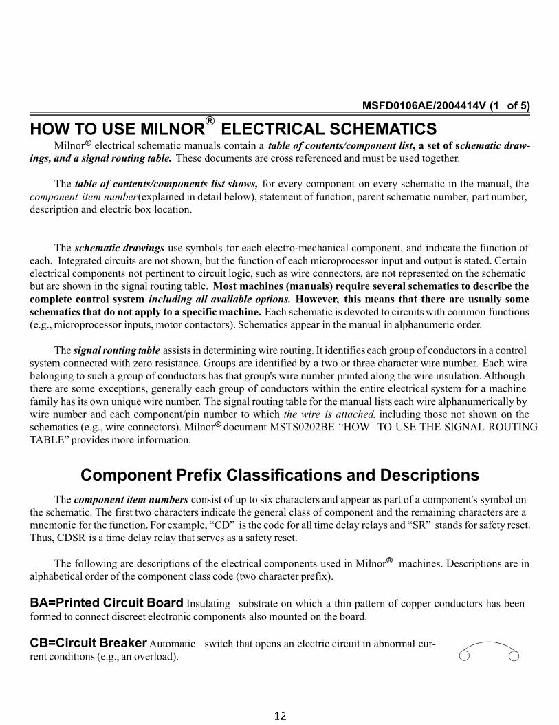
ELECTRICAL SCHEMATICSMilnor electrical schematic manuals contain a table of contents/component list, a set of schematic draw-
ings, and a signal routing table. These documents are cross referenced and must be used together.
The table of contents/components list shows, for every component on every schematic in the manual, the
component item number(explained in detail below), statement of function, parent schematic number, part number,
description and electric box location.
The schematic drawings use symbols for each electro-mechanical component, and indicate the function of
each. Integrated circuits are not shown, but the function of each microprocessor input and output is stated. Certain
electrical components not pertinent to circuit logic, such as wire connectors, are not represented on the schematic
but are shown in the signal routing table. Most machines (manuals) require several schematics to describe the
complete control system including all available options. However, this means that there are usually some
schematics that do not apply to a specific machine. Each schematic is devoted to circuits with common functions
(e.g., microprocessor inputs, motor contactors). Schematics appear in the manual in alphanumeric order.
The signal routing table assists in determining wire routing. It identifies each group of conductors in a control
system connected with zero resistance. Groups are identified by a two or three character wire number. Each wire
belonging to such a group of conductors has that group's wire number printed along the wire insulation. Although
there are some exceptions, generally each group of conductors within the entire electrical system for a machine
family has its own unique wire number. The signal routing table for the manual lists each wire alphanumerically by
wire number and each component/pin number to which the wire is attached, including those not shown on the
schematics (e.g., wire connectors). Milnor document MSTS0202BE “HOW TO USE THE SIGNAL ROUTING
TABLE” provides more information.
Component Prefix Classifications and DescriptionsThe component item numbers consist of up to six characters and appear as part of a component's symbol on
the schematic. The first two characters indicate the general class of component and the remaining characters are a
mnemonic for the function. For example, “CD” is the code for all time delay relays and “SR” stands for safety reset.
Thus, CDSR is a time delay relay that serves as a safety reset.
The following are descriptions of the electrical components used in Milnor machines. Descriptions are in
alphabetical order of the component class code (two character prefix).
ÀBA=Printed Circuit Board Insulating substrate on which a thin pattern of copper conductors has been
formed to connect discreet electronic components also mounted on the board.
ÀCB=Circuit Breaker Automatic switch that opens an electric circuit in abnormal cur-
rent conditions (e.g., an overload).
R
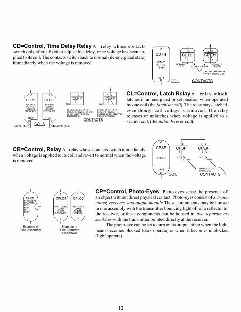
ÀCD=Control, Time Delay Relay A relay whose contacts
switch only after a fixed or adjustable delay, once voltage has been ap-
plied to its coil. The contacts switch back to normal (de-energized state)
immediately when the voltage is removed.
À
CL=Control, Latch Relay A re la y w hic h
latches in an energized or set position when operated
by one coil (the latch/set coil). The relay stays latched,
even though coil voltage is removed. The relay
releases or unlatches when voltage is applied to a
second coil, (the unlatch/reset coil).
ÀCR=Control, Relay A relay whose contacts switch immediately
when voltage is applied to its coil and revert to normal when the voltage
is removed.
À
CP=Control, Photo-Eyes Photo-eyes sense the presence of
an object without direct physical contact. Photo-eyes consist of a trans-
mitter, receiver, and output module.These components may be housed
in one assembly with the transmitter bouncing light off of a reflector to
the receiver, or these components can be housed in two separate as-
semblies with the transmitter pointed directly at the receiver.
The photo-eye can be set to turn on its output either when the light
beam becomes blocked (dark operate) or when it becomes unblocked
(light operate).
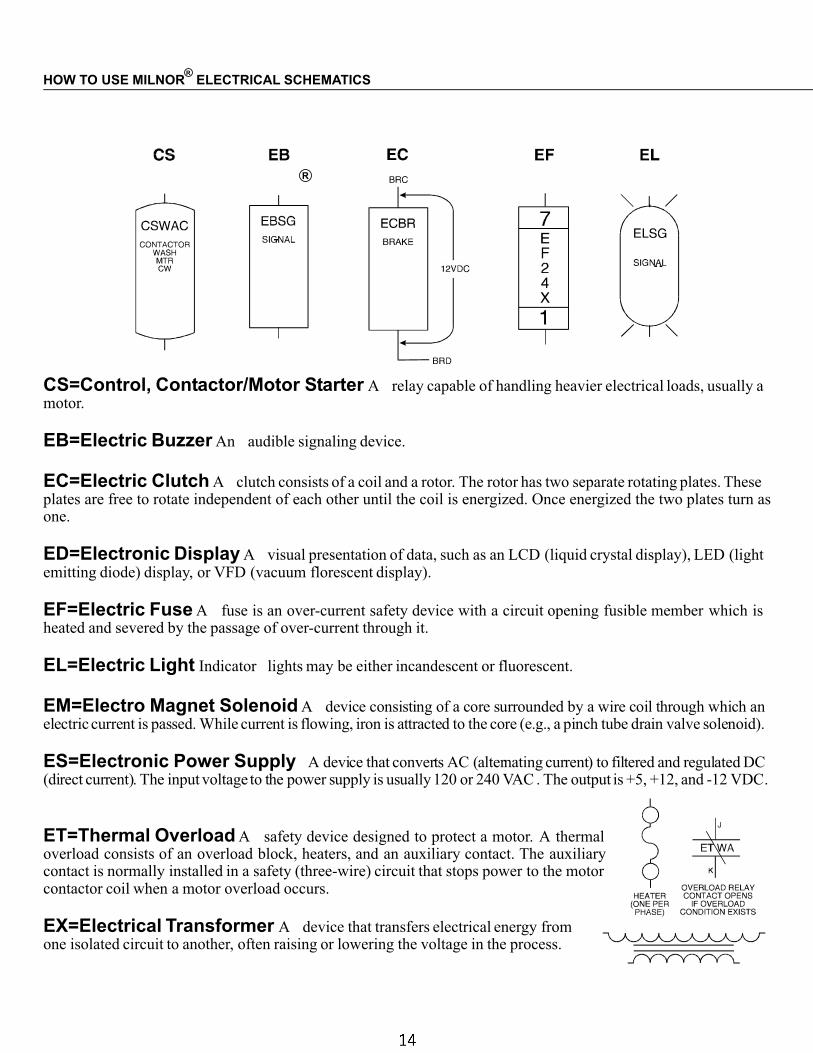
ÀCS=Control, Contactor/Motor Starter A relay capable of handling heavier electrical loads, usually amotor.
ÀEB=Electric Buzzer An audible signaling device.
ÀEC=Electric Clutch A clutch consists of a coil and a rotor. The rotor has two separate rotating plates. Theseplates are free to rotate independent of each other until the coil is energized. Once energized the two plates turn asone.
ÀED=Electronic Display A visual presentation of data, such as an LCD (liquid crystal display), LED (lightemitting diode) display, or VFD (vacuum florescent display).
ÀEF=Electric Fuse A fuse is an over-current safety device with a circuit opening fusible member which isheated and severed by the passage of over-current through it.
ÀEL=Electric Light Indicator lights may be either incandescent or fluorescent.
ÀEM=Electro Magnet Solenoid A device consisting of a core surrounded by a wire coil through which anelectric current is passed. While current is flowing, iron is attracted to the core (e.g., a pinch tube drain valve solenoid).
ÀES=Electronic Power Supply A device that converts AC (alternating current) to filtered and regulated DC(direct current). The input voltage to the power supply is usually 120 or 240 VAC . The output is +5, +12, and -12 VDC.
ÀET=Thermal Overload A safety device designed to protect a motor. A thermaloverload consists of an overload block, heaters, and an auxiliary contact. The auxiliarycontact is normally installed in a safety (three-wire) circuit that stops power to the motorcontactor coil when a motor overload occurs.
ÀEX=Electrical Transformer A device that transfers electrical energy fromone isolated circuit to another, often raising or lowering the voltage in the process.
HOW TO USE MILNOR ELECTRICAL SCHEMATICS
R
R
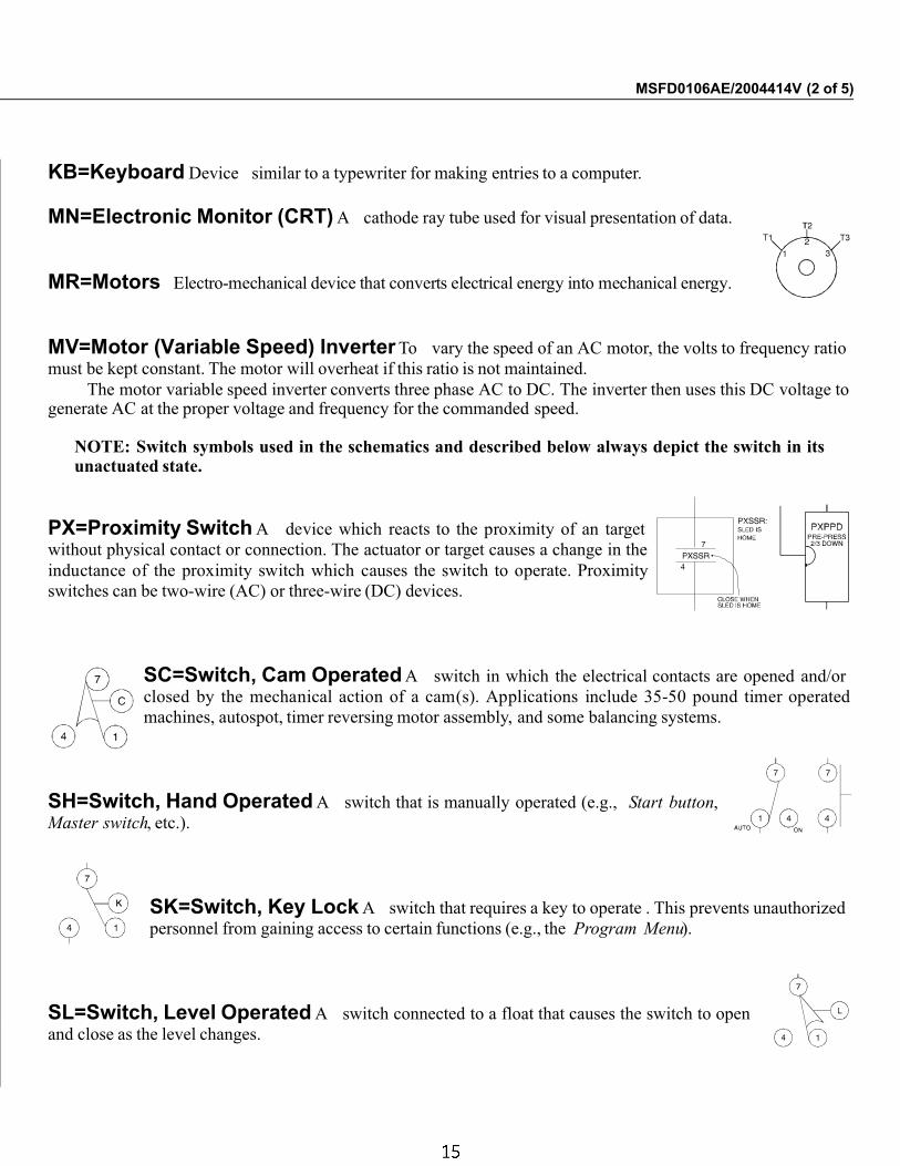
ÀKB=Keyboard Device similar to a typewriter for making entries to a computer.
ÀMN=Electronic Monitor (CRT) A cathode ray tube used for visual presentation of data.
ÀMR=Motors Electro-mechanical device that converts electrical energy into mechanical energy.
ÀMV=Motor (Variable Speed) Inverter To vary the speed of an AC motor, the volts to frequency ratio
must be kept constant. The motor will overheat if this ratio is not maintained.
The motor variable speed inverter converts three phase AC to DC. The inverter then uses this DC voltage togenerate AC at the proper voltage and frequency for the commanded speed.
NOTE: Switch symbols used in the schematics and described below always depict the switch in itsunactuated state.
ÀPX=Proximity Switch A device which reacts to the proximity of an target
without physical contact or connection. The actuator or target causes a change in the
inductance of the proximity switch which causes the switch to operate. Proximity
switches can be two-wire (AC) or three-wire (DC) devices.
ÀSC=Switch, Cam Operated A switch in which the electrical contacts are opened and/or
closed by the mechanical action of a cam(s). Applications include 35-50 pound timer operated
machines, autospot, timer reversing motor assembly, and some balancing systems.
ÀSH=Switch, Hand Operated A switch that is manually operated (e.g., Start button,
Master switch, etc.).
ÀSK=Switch, Key Lock A switch that requires a key to operate . This prevents unauthorized
personnel from gaining access to certain functions (e.g., the Program Menu).
ÀSL=Switch, Level Operated A switch connected to a float that causes the switch to open
and close as the level changes.
MSFD0106AE/2004414V (2 of 5)
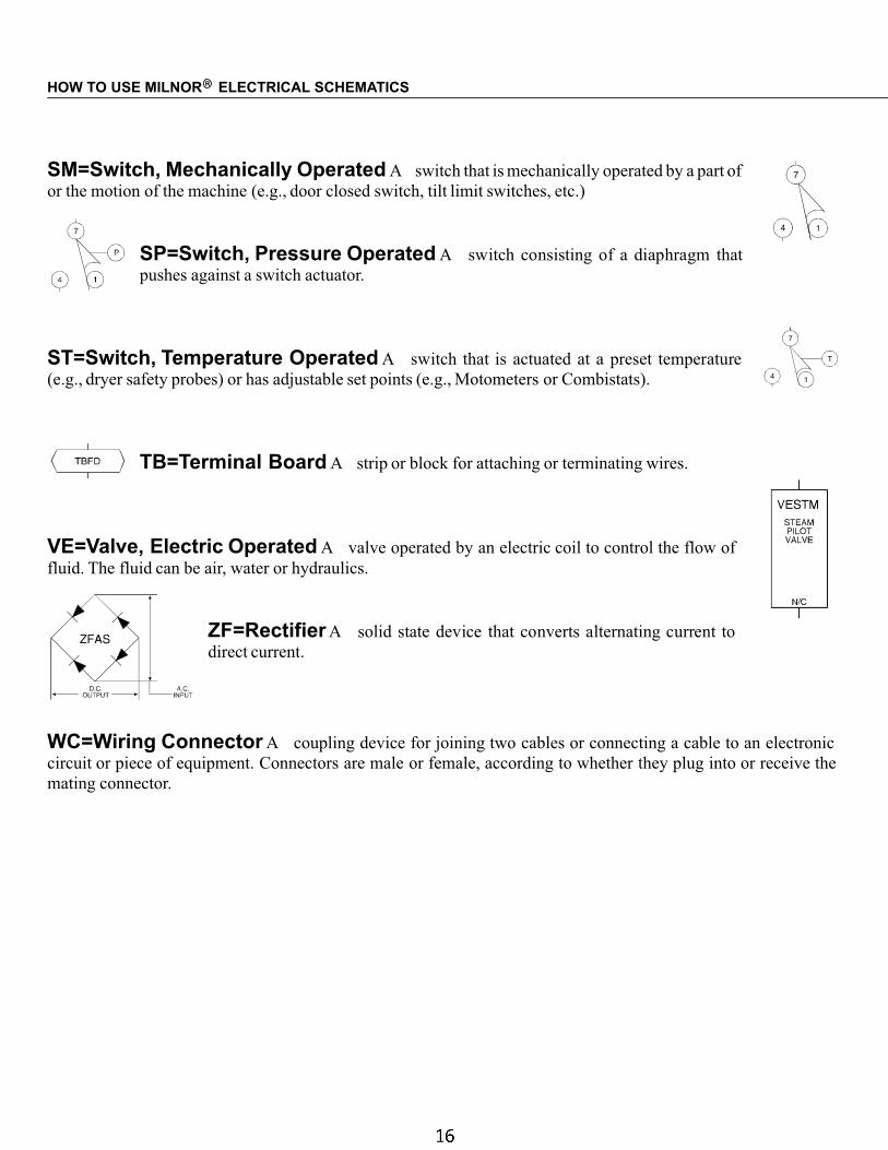
ÀSM=Switch, Mechanically Operated A switch that is mechanically operated by a part of
or the motion of the machine (e.g., door closed switch, tilt limit switches, etc.)
ÀSP=Switch, Pressure Operated A switch consisting of a diaphragm that
pushes against a switch actuator.
ÀST=Switch, Temperature Operated A switch that is actuated at a preset temperature
(e.g., dryer safety probes) or has adjustable set points (e.g., Motometers or Combistats).
ÀTB=Terminal Board A strip or block for attaching or terminating wires.
ÀVE=Valve, Electric Operated A valve operated by an electric coil to control the flow of
fluid. The fluid can be air, water or hydraulics.
ÀZF=Rectifier A solid state device that converts alternating current to
direct current.
À
WC=Wiring Connector A coupling device for joining two cables or connecting a cable to an electronic
circuit or piece of equipment. Connectors are male or female, according to whether they plug into or receive the
mating connector.
HOW TO USE MILNOR ELECTRICAL SCHEMATICSR
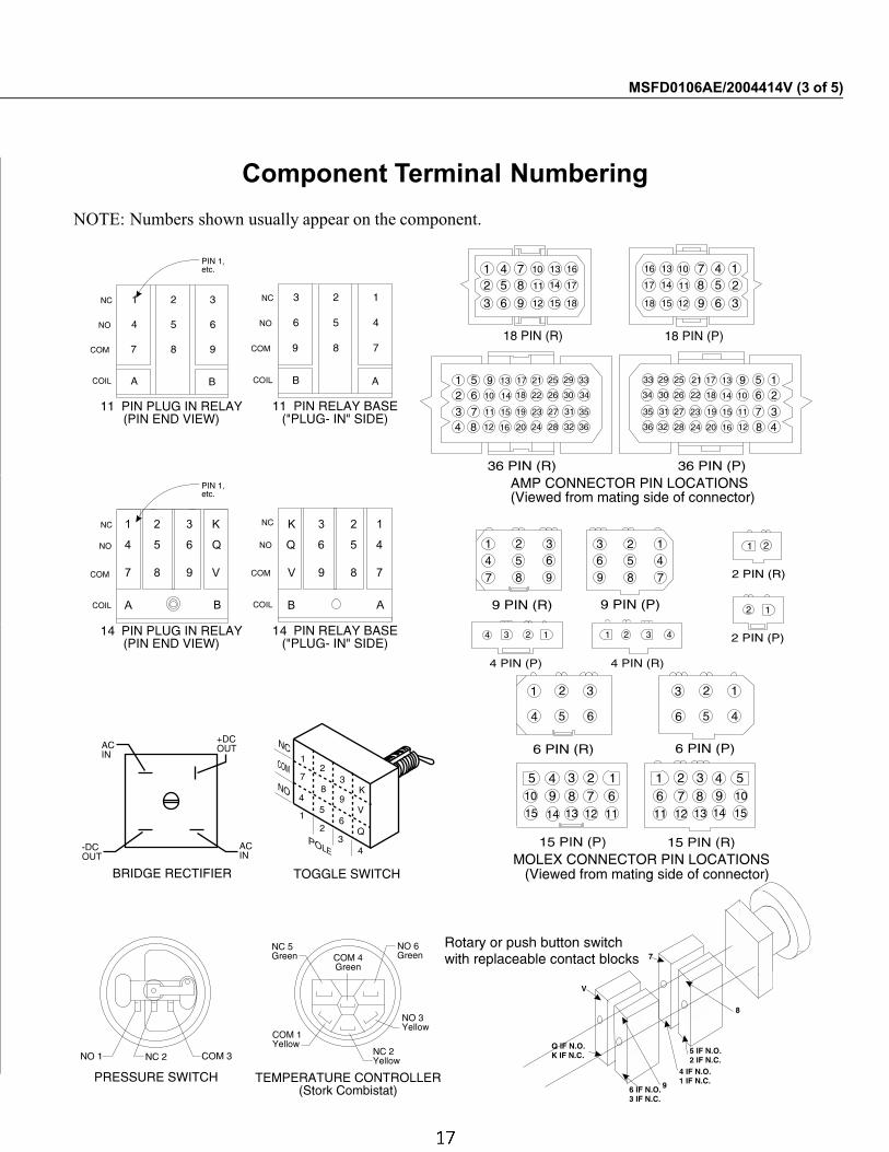
Component Terminal Numbering
NOTE: Numbers shown usually appear on the component.
MSFD0106AE/2004414V (3 of 5)
4 5 6 Q Q 6 5 4
7 8 9 V V 9 8 7
1 2 3 K K 3 2 1
A BB A
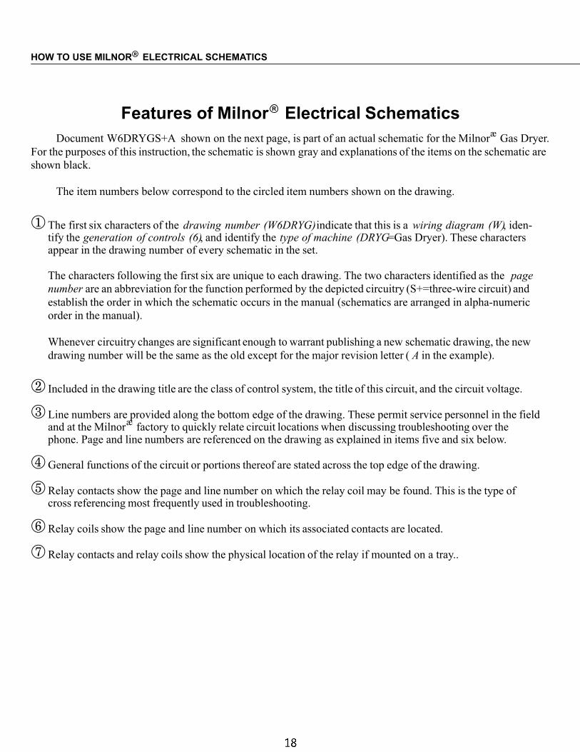
Features of Milnor R Electrical SchematicsDocument W6DRYGS+A shown on the next page, is part of an actual schematic for the Milnor
æGas Dryer.
For the purposes of this instruction, the schematic is shown gray and explanations of the items on the schematic are
shown black.
The item numbers below correspond to the circled item numbers shown on the drawing.
� The first six characters of the drawing number (W6DRYG)indicate that this is a wiring diagram (W), iden-tify the generation of controls (6), and identify the type of machine (DRYG=Gas Dryer). These charactersappear in the drawing number of every schematic in the set.
The characters following the first six are unique to each drawing. The two characters identified as the page
number are an abbreviation for the function performed by the depicted circuitry (S+=three-wire circuit) and
establish the order in which the schematic occurs in the manual (schematics are arranged in alpha-numeric
order in the manual).
Whenever circuitry changes are significant enough to warrant publishing a new schematic drawing, the new
drawing number will be the same as the old except for the major revision letter ( A in the example).
� Included in the drawing title are the class of control system, the title of this circuit, and the circuit voltage.
� Line numbers are provided along the bottom edge of the drawing. These permit service personnel in the fieldand at the Milnor
æfactory to quickly relate circuit locations when discussing troubleshooting over the
phone. Page and line numbers are referenced on the drawing as explained in items five and six below.
� General functions of the circuit or portions thereof are stated across the top edge of the drawing.
� Relay contacts show the page and line number on which the relay coil may be found. This is the type ofcross referencing most frequently used in troubleshooting.
� Relay coils show the page and line number on which its associated contacts are located.
� Relay contacts and relay coils show the physical location of the relay if mounted on a tray..
HOW TO USE MILNOR ELECTRICAL SCHEMATICSR

� The designation MTA applies to electronic circuit board connections. Typically, a control system will con-tain several different types of circuit boards and one or more boards of each type. A numerical suffix iden-tifies the board type and a numerical prefix identifies which one of several boards of a given type is beingdepicted. For example, the designation 1MTA5 identifies this as the first I/O board (8 output, 16 inputboard) in the control system. As shown on the drawing, a pin number follows the board number, separatedby a dash. Thus, 1MTA5-9 is pin 9 on this board. The numerical designations for board types vary from onecontrol system to another. Some of the board types commonly encountered on the Mark II washer-extractorcontrol and their designations are as follows:
MTA1-MTA6 = 8 output, 16 input (8/16) boards.
MTA11-MTA16 = 16 output boards
MTA30-MTA40 = processor boards
MTA41-MTA43 = digital to analog (D/A) boards
MTA51-MTA56 = analog to digital (A/D) boards
The complete listing of the boards utilized in a given control system can be found in the component list for
that system.
The wire numbers, as described in the explanation of the signal routing table at the beginning of this section,
are shown at appropriate locations on the schematic drawing.
Where diamond symbols appear at the end of a conductor, these are match points for continuing the
schematic on another drawing. The page and line number that continues the circuit is printed adjacent to the
diamond symbol. Where more than one match point appears on the referenced page, match diamonds con-
taining corresponding letters.
MSFD0106AE/2004414V(4 of 5)
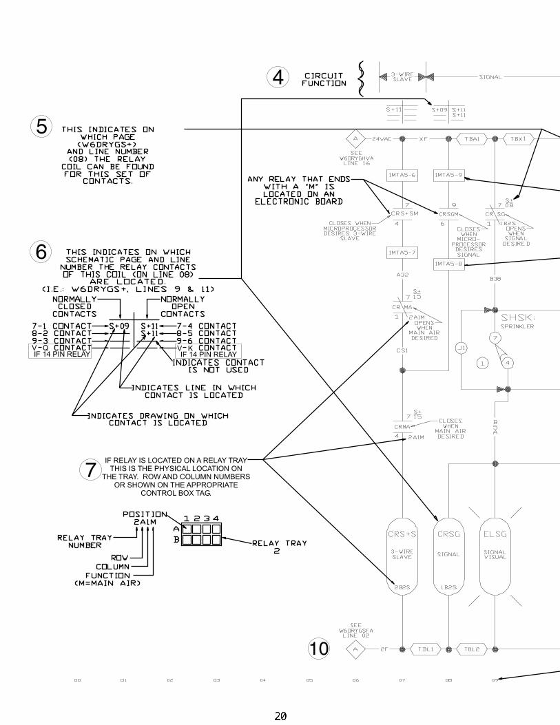
6
5
10
7
4
V Q V KIF 14 PIN RELAYIF 14 PIN RELAY
IF RELAY IS LOCATED ON A RELAY TRAY
THIS IS THE PHYSICAL LOCATION ON
THE TRAY. ROW AND COLUMN NUMBERS
OR SHOWN ON THE APPROPRIATE
CONTROL BOX TAG.
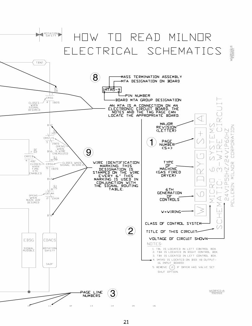
1
2
3
8
9
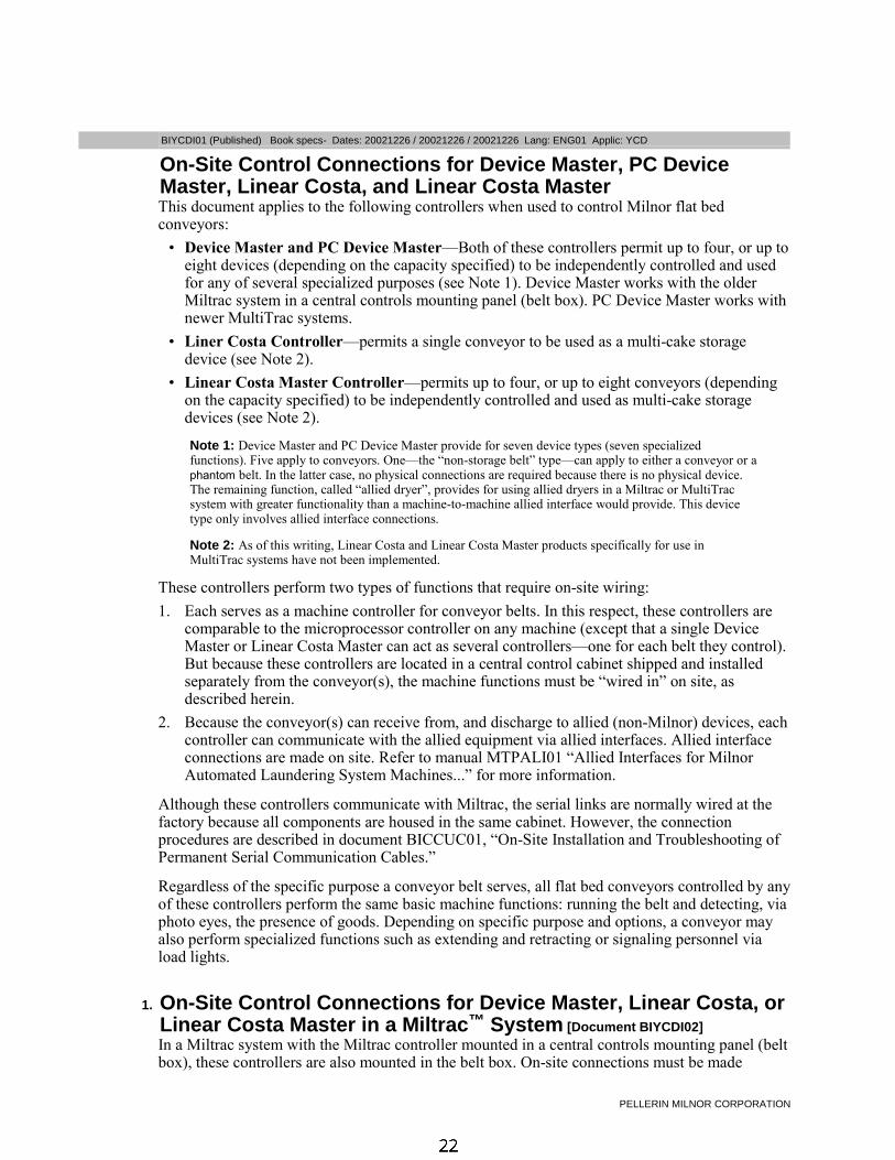
PELLERIN MILNOR CORPORATION
BIYCDI01 (Published) Book specs- Dates: 20021226 / 20021226 / 20021226 Lang: ENG01 Applic: YCD
On-Site Control Connections for Device Master, PC DeviceMaster, Linear Costa, and Linear Costa MasterThis document applies to the following controllers when used to control Milnor flat bedconveyors:
• Device Master and PC Device Master—Both of these controllers permit up to four, or up toeight devices (depending on the capacity specified) to be independently controlled and usedfor any of several specialized purposes (see Note 1). Device Master works with the olderMiltrac system in a central controls mounting panel (belt box). PC Device Master works withnewer MultiTrac systems.
• Liner Costa Controller—permits a single conveyor to be used as a multi-cake storagedevice (see Note 2).
• Linear Costa Master Controller—permits up to four, or up to eight conveyors (dependingon the capacity specified) to be independently controlled and used as multi-cake storagedevices (see Note 2).
Note 1: Device Master and PC Device Master provide for seven device types (seven specializedfunctions). Five apply to conveyors. One—the “non-storage belt” type—can apply to either a conveyor or aphantom belt. In the latter case, no physical connections are required because there is no physical device.The remaining function, called “allied dryer”, provides for using allied dryers in a Miltrac or MultiTracsystem with greater functionality than a machine-to-machine allied interface would provide. This devicetype only involves allied interface connections.
Note 2: As of this writing, Linear Costa and Linear Costa Master products specifically for use inMultiTrac systems have not been implemented.
These controllers perform two types of functions that require on-site wiring:
1. Each serves as a machine controller for conveyor belts. In this respect, these controllers arecomparable to the microprocessor controller on any machine (except that a single DeviceMaster or Linear Costa Master can act as several controllers—one for each belt they control).But because these controllers are located in a central control cabinet shipped and installedseparately from the conveyor(s), the machine functions must be “wired in” on site, asdescribed herein.
2. Because the conveyor(s) can receive from, and discharge to allied (non-Milnor) devices, eachcontroller can communicate with the allied equipment via allied interfaces. Allied interfaceconnections are made on site. Refer to manual MTPALI01 “Allied Interfaces for MilnorAutomated Laundering System Machines...” for more information.
Although these controllers communicate with Miltrac, the serial links are normally wired at thefactory because all components are housed in the same cabinet. However, the connectionprocedures are described in document BICCUC01, “On-Site Installation and Troubleshooting ofPermanent Serial Communication Cables.”
Regardless of the specific purpose a conveyor belt serves, all flat bed conveyors controlled by anyof these controllers perform the same basic machine functions: running the belt and detecting, viaphoto eyes, the presence of goods. Depending on specific purpose and options, a conveyor mayalso perform specialized functions such as extending and retracting or signaling personnel viaload lights.
1. On-Site Control Connections for Device Master, Linear Costa, orLinear Costa Master in a Miltrac™ System [Document BIYCDI02]In a Miltrac system with the Miltrac controller mounted in a central controls mounting panel (beltbox), these controllers are also mounted in the belt box. On-site connections must be made

On-Site Control Connections for Device Master, PC Device Master, Linear Costa, and Linear Costa Master
PELLERIN MILNOR CORPORATION
between the controller box in the belt box and each conveyor. The standard controller-to-conveyor connections, which are the same for all three controllers, are shown in Table 1.Connections for specialized conveyor functions and for allied interfaces are not shown. Refer tothe controller schematic and reference manuals, and the system layout drawings for moreinformation.
Table 1: Standard On-Site Control Connections for Device Master, Linear Costa, and Linear CostaMaster in Systems With a Miltrac Belt Box
Connection Point
In Controller Box On MilnorConveyorPurpose Cable Specification
Connector Pin Wire (tagged)**
ETOL**** T1 T1
ETOL**** T2 T2
ETOL**** T3 T3
Motor feeds(when motorcontactors are inbelt box)
One set of four conductors (3-phasewiring plus ground). Eachconductor: 14AWG (2.5mm²) with600VAC insulation TB2F
(ground) any yellow/greenground wire
TBL 1***Emergency Stoppull cords TBL 2***
Safety switch
TB24 any 24VDC24VDC Photoeye power TB2G
(ground) any 2G
TB_* 5 Load end phooeyinput
Microprocessorinputs fromphoto eyes
Multi-conductor cable: 18AWG(1.0mm²) with 300VAC colorcoded insulation. Ground unusedwires, one end only.
TB_* 6 Discharge endphooey input
* Character in third position varies with the (device) as follows: B = belt 0, D = belt 1, E =belt 2, F = belt 3, G = belt 4, H = belt 5, J = belt 6, K = belt 7. Example: TBB is for belt 0.
** Wire-to-wire connections (white cap). Wires are located in one or more junction boxesmounted on the conveyor. Wires are tagged and/or color coded, as indicated.
*** In the controller box, connect the Emergency Stop switches from all conveyors togetherin series, using wire-to-wire (white cap) connections, then connect the entire series into theDevice Master 3-wire circuit at this location. Pulling any pull cord must cause all conveyorsto stop functioning until the controller is restarted.
**** The motor contactors/overloads are labeled "belt 0", belt 1", etc.
2. On-Site Control Connections for PC Device Master in aMultiTrac™ System [Document BIYCDI03]PC Device Master incorporates both a microprocessor controller located in the MultiTrac cabinetand PC Device Master software running on the MultiTrac PC. On-site connections must be madebetween The Device Master controller in the MultiTrac cabinet and each Device Master-controlled device. The standard connection points for connections between Device Master and aMilnor flat bed conveyor used as a Device Master device are shown in Table 2. Connections forspecialized conveyor functions and for the allied dryer device type (which only involves alliedinterface connections) are not shown. Refer to the Device Master schematic and referencemanuals and the system layout drawings for more information.
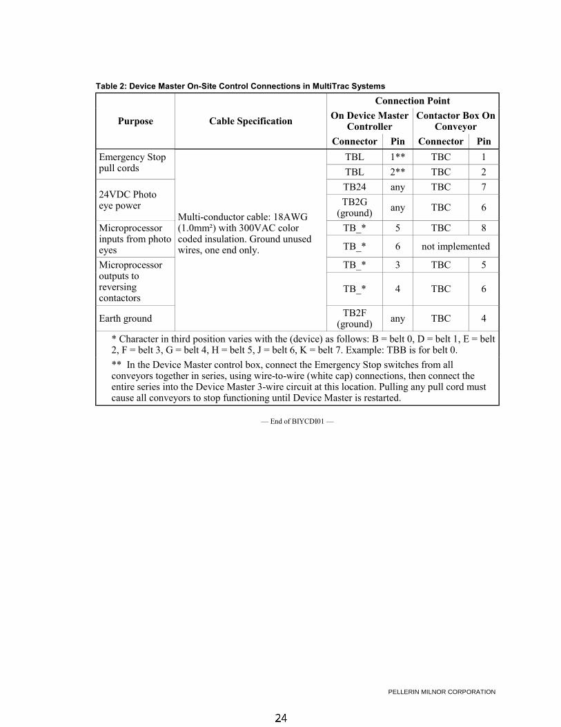
PELLERIN MILNOR CORPORATION
Table 2: Device Master On-Site Control Connections in MultiTrac Systems
Connection Point
On Device MasterController
Contactor Box OnConveyorPurpose Cable Specification
Connector Pin Connector Pin
TBL 1** TBC 1Emergency Stoppull cords TBL 2** TBC 2
TB24 any TBC 724VDC Photoeye power TB2G
(ground) any TBC 6
TB_* 5 TBC 8Microprocessorinputs from photoeyes TB_* 6 not implemented
Multi-conductor cable: 18AWG(1.0mm²) with 300VAC colorcoded insulation. Ground unusedwires, one end only.
TB_* 3 TBC 5Microprocessoroutputs toreversingcontactors
TB_* 4 TBC 6
Earth ground TB2F(ground) any TBC 4
* Character in third position varies with the (device) as follows: B = belt 0, D = belt 1, E = belt2, F = belt 3, G = belt 4, H = belt 5, J = belt 6, K = belt 7. Example: TBB is for belt 0.
** In the Device Master control box, connect the Emergency Stop switches from allconveyors together in series, using wire-to-wire (white cap) connections, then connect theentire series into the Device Master 3-wire circuit at this location. Pulling any pull cord mustcause all conveyors to stop functioning until Device Master is restarted.
— End of BIYCDI01 —