Embed Size (px)
Citation preview

Reduced wiring system
EX500-GDN1
Instruction ManualDeviceNet Compatible GW Unit
URL http://www.smcworld.com

Thank you for purchasing the SMC reduced wiring system EX500 series.
Please read this instruction manual carefully and understand the contents before
use so that you can operate this unit safely and correctly.
Please keep this manual handy for future reference.
SAFETY ..........................................................................................................2
Product Summary............................................................................................5
EX500
Part Names ...................................................................................................6
Dimensions ...................................................................................................7
Installation.....................................................................................................7
Specification..................................................................................................8
Wiring..........................................................................................................11
Display/Switch setting .................................................................................18
SI Unit
Part Names .................................................................................................20
Dimensions .................................................................................................21
Mounting/Wiring ..........................................................................................22
Specification................................................................................................23
Display ........................................................................................................24
Input Unit Manifold
Part Names .................................................................................................25
Dimensions .................................................................................................26
Installation...................................................................................................27
Specification................................................................................................28
Wiring..........................................................................................................29
Display ........................................................................................................30
EX9 Series General Purpose Output Block
Part Names .................................................................................................31
Dimensions .................................................................................................32
Mounting .....................................................................................................33
Wiring..........................................................................................................34
Specification................................................................................................36
Display .......................................................................................................37
Option............................................................................................................38
Troubleshooting.............................................................................................40
OPERATORThis instruction manual has been written for those who have knowledge of
machines and equipments that use reduced wiring system as well as the
sufficient knowledge to assemble, operate, and maintain such devices.
Before performing assembly, operation and/or maintenance, please read
this manual carefully and understand the contents.
Contents

2 3
SAFETYThe body of unit and this manual contain the essential information for the protection ofusers and others from possible injury and property damage and to ensure correcthandling.Please check that you fully understand the definitions of the following messages( symbols ) before going on to read the body of this manual, and always follow theinstructions. Please also read the instruction manuals etc. of related machines and equipments andunderstand the contents before use.
IMPORTANT MESSAGES
Indicates a potentially hazardous situation that could result indeath or severe injury if you do not follow instructions.
Read this manual and follow its instructions. Signal words such as WARNING,CAUTION and NOTE will be followed by important safety information that must becarefully reviewed.
Indicates a potentially hazardous situation that, if not avoided,may result in minor injury or moderate injury.
Gives you helpful information.NOTE
Do not disassemble, modify ( including modification of printed circuit board ) or repair.Otherwise injury or failure can result.
Do not operate beyond specification range.Otherwise fire, malfunction or damage to the reduced wiring system can result.Confirm the specifications before operation.
Do not operate in atmosphere of flammable/explosive/corrosive gas.Otherwise fire, explosion or corrosion can result.This reduced wiring system is not explosion-proof type.
For use in interlock circuit:Provide double interlock system by adding different type of protection( such as mechanical protection ). Check that the interlock circuit is working normally.
Otherwise accident caused by malfunction can result.
Before performing maintenance:Turn off power supply.Stop air supply, exhaust compressed air in piping, and confirm the releaseto atmosphere.
Otherwise injury can result.
Conduct proper functional inspection after completing maintenance.In the case of abnormality such as unit does not work normally, stop the operation.Otherwise safety cannot be assured due to unintended malfunction.
Provide grounding to improve safety and noise resistance of reduced wiringsystem.Provide grounding as close to the unit as possible to shorten distance for grounding.
1. UL508-compatible limited voltage/current circuitA circuit using the secondary coil of an insulating transformer that meets following conditionsas power source.Maximum voltage ( at no load ) : 30Vrms ( 42.4Vpeak ) or belowMaximum current: ( 1 ) 8A or less ( including when short-circuited )
( 2 ) When limited by the circuit protector ( such as fuse )having the following rating.
2. UL1310-compatible Class 2 power supply unit or circuit of max. 30Vrms ( 42.4Vpeak ) or lessusing a UL1585-compatible Class 2 transformer as power source. ( Class 2 circuit )
No-Load Voltage ( Vpeak ) Max. Current Rating ( A )
0 to 20 [V] 5.0
Above 20 [V] to 30 [V] 100/peak voltage
Handling precautionsUse the following UL-recognized DC power supply to combine with.
4 5
SAFETY ( continued )
Follow the instructions given below when handling your reduced wiring system.Otherwise a damage or failure to cause a malfunction can result.
Operate the reduced wiring system at the specified voltage.Reserve space for maintenance.Do not remove any name plate or label.Do not drop, hit or apply an excessive shock to the unit.Follow the specified tightening torque.Do not apply any excessive force to cables by repeated bending, tensioning or placing aheavy object on the cables.Connect wires and cables correctly.Do not perform any wiring work while the power is on.Do not use the reduced wiring system on the same wiring route as the power line or highvoltage line.Confirm the insulation of wiring.Perform the power supply wiring by dividing into two lines ---- one is for power supply for outputand the other is for power supply for input and controlling GW/SI.Take sufficient measures against noise such as noise filter when incorporating the reducedwiring system into a machine or equipment.Mount a terminal plug or a waterproof cap on each unused M12 connector for input/output( communication connector, communication ports A - D, and power supply for input andcontrolling GW/SI ).Take sufficient shielding measures when operating the product in any of the following places.( 1 ) A place where noise due to static electricity etc. is generated( 2 ) A place of high electric field strength( 3 ) A place where exposure to radioactivity is possible( 4 ) A place near power cableDo not operate the product in a place where there is a source of surge.Use a surge absorbing element built-in type to directly drive the load that generates surgevoltage such as solenoid valve.Prevent any foreign matter such as remnant of wires from getting inside the product whenopening the station number switch protective cover.Install the reduced wiring system in a place free from vibration and impact.Operate the product in the specified ambient temperature range.Do not use in a place to be affected by the radiant heat from a surrounding heat source.Set the DIP switch and rotary switch by using a sharp-pointed watchmakers screwdriver etc.Perform the maintenance regularly.Conduct an appropriate functional inspection after completing the maintenance.Do not use chemicals such as benzin and thinner to clean the product.
Product Summary
System configuration
GW unitManifold valve with SI unit( SV/VQC series )
Input unitmanifold
DeviceNetcommunication connector
Power supplyconnector cable( DC24V for solenoidvalves/output, DC24V forinput and controlling GW/SI )
Branch cablewith M12 connector Branch cable
with M12 connectorInput unit manifold
Manifold valvewith SI unit( SV/VQC series )
The reduced wiring system is connected to various kinds of fieldbus realizes thereduced wiring and decentralized installation of I/O devices . The signals to/fromfieldbus are exchanged by GW unit, and the signals to/from decentralized I/O devicesare collected and delivered by GW unit.The maximum number of connections of manifold valve/Input unit manifold is16/branch x 4 branches = 64 points each for output and input.
As the cables with connectors are used for all wirings among devices, the systemcomplies with the IP65 environment.

6 7
EX500 Part Names
MSNSSOL
BUS
EX500-GDN1
Communicationconnector
1
2
3
4
5
6
7
8
Note1: For wiring method, refer to subsection "Wiring" ( page 11 ) of section "EX500" in thismanual.
Note2: For display and setting method, refer to subsection "Display/Switch Setting" ( page 18 )of section "EX500" in this manual.
Power supply connector
Communication port A( COM A )
Communication port B( COM B )
Communication port C( COM C )
Communication port D( COM D )
Display
Connect with DeviceNet line. ( Note 1 )
NameNo. Application
Supply power for output devices such as solenoidvalve, for input devices such as sensor, and forcontrolling GW/SI by using power supply connectorcable. ( Note1 )
Display the power supply status and communicationstatus with PLC. ( Note2 )
Station number switchprotective cover
Set address and data rate by using the switchesunder this cover. ( Note2 )
Connect SI unit ( manifold valve ) or Input unit byusing branch cable with M12 connectors. ( Note1 )
Dimensions ( unit: mm )
EX
500-G
DN
1
24VDC COM A COM B COM C COM D
BUSMS
NS
SOL
88
1046 48
.8
136160
GATEWAY UNITEX500 SERIES
PE
EX500 body
Cutout Dimensions for Mounting ( Tolerance : 0.2 )
148
68
5
4 M5
*Tightening torque : (1.5 0.2 ) Nm
Installation ( unit: mm )
Thread mountingSecure at four positions with screws with head diameter of 5.2 or more and threadlength of 15mm or more.

8 9
Specification
Basic specifications
Rated voltage DC24V
Range of powersupply voltage
Power supply for input and controlling GW/SI: DC24V 10%Power supply for output: DC24V+10%/-5% ( Voltage dropwarning at around 20V )
Rated current Power supply for input and controlling GW/SI: 3.0AInside GW unit: 0.2AInput device and SI control section: 2.8A
Power supply for solenoid valves and output: 3A
Number of input/output points
Input point: max. 64/Output point: max 64
Higher-level bus
Protocol DeviceNet Release 2.0
Slave ( slave station ) type
MAC ID setting range
Group2 only server
0 - 63
Device information
Applicable message
I/O message size
Date rate
Vender code: 7 ( SMC Corp. )Product type: 12 ( communication adapter )Product code: 5001
Duplicate MAC ID check messageGroup2 only unconnected explicit messageExplicit messagePoll I/O message
Input: 8 bytesOutput: 8 bytes
125kbps, 250kbps, 500kbps
Transmission distance
Insulation method
Refer to the next page.
Photocoupler
( )
Transmission distance
Network length
Terminatingresistor
Node
NodeNode
Multi-branchT-branch
Node
Terminatingresistor
Node
Node
Node
Trunk line
Multi-branchDrop
lineDropline
Max.6m Drop line branch
Multi-branch
Dropline
Node Node
DeviceNet allows T-branch, multi-branch and drop line branch connections.Total extended length of trunk line and drop lines depends on the date rate and thethickness of communication cable. The connection type for EX500 series is T-branch only.
Item
Maximumnetwork length
Total drop line length
Terminating resistor
Thick cable
Thin cable
Date rate ( kbps )
125 250 500
500m or less 250m or less 100m or less
100m or less
156m or less 78m or less 39m or less
Note: Maximum length per drop line is 6m.
121 , 1/2W ( brown/red/brown/black/brown )

10 11
WiringSpecification ( continued )
The wirings are described in the following order.
Communication wiring: Connection with DeviceNet
Power supply wiring: Connections of power supplies forsolenoid valves/output devices, andfor input devices and controlling GW/SI
Powersupplyconnector
Power supplyfor output
Power supplyfor input andcontrolling GW/SI
DRAIN2V+
+24V
+24V
3V -4CAN H
0V230V45PE
RD+2 RD -3 TD+4 TD -5 +24V6 0V7 +24V8 0V
COM A
RD+2 RD -3 TD+4 TD -5 +24V6 0V7 +24V8 0V
COM D
5CAN L
1
1
1
1
Com
mun
icat
ion
conn
ecto
r
Inte
rnal
circ
uit
DC-DCconverter
(insulation)
Internal circuit
Branch wiring: Connection from GW unit to SI unit or Input unit
Lower-level bus
Number of branches forinput/output
4 branches ( 16 points/branch ) for input4 branches ( 16 points/branch ) for output
Communication method Protocol: Dedicated for SMCSpeed: 750kbps
Branch current for input( Note )
Max. 0.5 [A] per branch ( when SI unit and inputdevices are connected )
Branch current for output Max. 0.65 [A] per branch( when SI unit EX500-S 01 is connected )Max. 0.75 [A] per branch( when SI unit EX500-Q is connected )
Branch cable length 5m or less per branch( total extended length: 10m or less )
Note: Total value of maximum current consumption and maximum load current of input devicesto connect.
1ft 0.3048m
Item
Conductor’scross-section area
Color
Impedance
Propagation delay (Max.)
Attenuation rate(Max.)
Conductorresistance (Max.)
Signal
0.82mm2 1.65mm2 0.20mm2 0.33mm2
Blue, white Red, black
1.36ns/ft -
Blue, white Red, black
1.36ns/ft -
125kHz: 0.29dB/ft500kHz: 0.50dB/ft
1.00MHz: 0.70dB/ft
120 10%(1MHz)
- 120 10%(1MHz)
-
-125kHz: 0.13dB/ft500kHz: 0.25dB/ft
1.00MHz: 0.40dB/ft-
Thick cable Thin cable
Power Signal Power
6.9 /1000ft 3.6/1000ft
28 /1000ft 17.5/1000ft
Cable specification
12 13
Wiring ( continued )
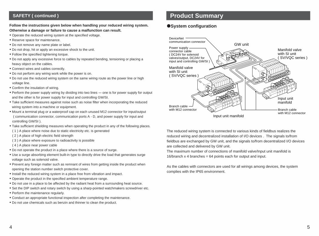
Communication wiring
Aligning the key groove with the communication connector( 5-pin, plug ) of GW unit, plug the DeviceNetcommunication cable ( socket ).
Tighten the lock nut on cable side by turning itclockwise by hand.
Confirm that the connector portion does not move.
Pin layout and connection diagram of cable with DeviceNet communication connector
Cable connection
Connect the cable with DeviceNet communication connector to the communicationconnector of GW unit.
2 1
5
3 4
Connect the communication cable with socket-type M12 connector to thecommunication connector of GW unit.
2
4 3
5
1
Socket Connector Pin Layout
Connection of terminating resistor
To both ends of DeviceNet trunk line, be sure to connect terminating resistors. For terminating resistor, refer to subsection "Specification" ( page 8 ) of section "EX500"in this manual.
M12
14.9
EX500-AC0 -DN Connection Diagram
DRAIN 1 -V + 2V - 3 BlackCAN H 4 WhiteCAN L 5
Red
Blue
Core wire
Outside diameter
Sheath color
Cable specificationSignal wire AWG24 ( 41/0.08 ) Blue, white
Power wire
Drain wire
7
Light blue
AWG22 ( 19/0.16 )
AWG22 ( 19/0.16 )
Red, black
-
This cable is DeviceNet thin cable.Note 1
Power supply wiringConnect the power supply connector cable to the power supply connector of GW unit.There are two types of cables different in connector shape ---- straight type and angletype. With this cable, the power is supplied to the output devices such as solenoid valve,and the input devices such as sensor, and for controlling GW/SI. Therefore, there is noneed to supply the power to other units individually.When selecting the power supply, refer to "Handling precautions" ( page 3 ) in this manual.
Cable connection
Aligning the key groove with the power supplyconnector ( plug ) of GW unit, plug the power supplycable ( socket ).
Tighten the lock nut on cable side by turning itclockwise by hand.
Confirm that the connector portion does not move.
Pin layout and connection diagram of power supply connector cable for ( unit: mm )
( Pin layout and connection diagram are common to all cables. )
2
4 3
5
1
Socket Connector Pin Layout
Straight connector Type Angle connector Type
EX500-AP -S EX500-AP -A
M12M12
14.9
4834
18
6
30 5
50 31.3
28.3
30 5
50
6
Pin No.
5
4
3
2
1
Cable color: Signal name
Brown: 0V ( for solenoid valves/output )
White: DC24V+10%/-5% ( for solenoid valves/output )
Blue: 0V ( for input and controlling GW/SI )
Black: DC24V 10% (power supply for input and controlling GW/SI)
Gray: Ground ( PE )
NOTEConnect a ground cable of 100 or less to PE terminal.( The DRAIN and PE terminal of DeviceNet are connected inside GW unit throughcapacitor. )

14 15
Wiring ( continued )
Separate wiring for power supply for solenoid valves/output andfor input and control of GW/SI
Both single power supply and two power supply systems can be adopted, however, thewiring shall be made separately ( for solenoid valves/output and for input and controllingGW/SI ) for either system.
24VDC
24VDC
Brown: 0V ( for solenoid valves/output )
White: DC24V ( for solenoid valves/output )
Gray: Ground ( PE )
Blue: 0V ( for input and controlling GW/SI )
Black: DC24V ( for input and controlling GW/SI )
Cable Part No. : EX500-AP -
24VDC
Brown: 0V ( for solenoid valves/output )
White: DC24V ( for solenoid valves/output )
Gray: Ground ( PE )
Blue: 0V ( for input and controlling GW/SI )
Black: DC24V ( for input and controlling GW/SI )
Cable Part No. : EX500-AP -
Power supplyconnector
Power supplyconnector
1
3 4
52
1
3 4
52
A. Two power supply system
B. Single power supply system
Branch wiring ( wiring to communication ports )For wiring with solenoid valves or input devices, connect the branch cable with M12connector to communication ports A - D.There are two types of cables different in connector shape ---- straight type and angletype. As each cable contains power supply wire, there is no need to supply the power tosolenoid valves or input devices individually.
Cable connection
Aligning the key groove with theconnector ( socket ) of GW unit, plug inthe cable ( plug ). 2
3
4
5
6
7
18 1
7
6
5
4
3
28
Socket Connector Pin Layout Plug Connector Pin Layout
Tighten the lock nut on cable side byturning it clockwise by hand.
Confirm that the connector portion doesnot move.
NOTEMount a waterproof cap on each unused connector of GW unit. The proper use ofwaterproof cap can achieve IP65 Enclosure. ( Tightening torque: 0.1Nm for M12 )

16 17
Wiring (continued )
For GW unit – Manifold valve – Input unit manifold configuration
Two communication connectors in SI unit and one communication connector in Inputunit are installed respectively.To the communication connector ( C2 ) or ( 1 ) of SI unit, connect the branch cable withM12 connector from GW. To the communication connector ( C1 ) or ( 0 ), connect thebranch cable with M12 connector from Input unit.To the communication connector of Input unit, connect the branch cable with M12connector from SI unit.
GW unit
Manifold valve with SI unit( for SV/VQC series )
Connector (C1) / (0)
Branch cablewith M12 connector
Connector (C2) / (1)
Input unit manifold
Manifold valve with SI unit( for SV/VQC series )
Terminal plug
NOTEWhen no Input unit is connectedto the connector ( C1 ) or ( 0 ) ofSI unit, mount a terminal plug onthe connector.
For GW unit – Input unit manifold configuration
To the communication connector of Input unit, connect the branch cable with M12connector from GW unit.
Branch cablewith M12 connector
GW unit
Input unit manifold
Type, pin layout and connection diagram of the branch cable with M12 connector ( EX500-AC - )
M12
M12
48
16
52
L
M12
31.3
L
32.3
Straight Connector Type
M12
31.3
28.3
Angle Connector Type
EX500-AC -SSPS
EX500-AC -SAPA
L=300, 500, 1000, 3000, 5000 (mm)
14.9
6
6

SOL
NSMS
BUSGATEWAY UNIT
EX500 SERIES
COM A COM B COM C COM D
18 19
Display/Switch Setting
Settings for display
MS
NS
SOL
Lights on in green:Normal status.Lights on in red: Fatal failure occurred.
Lights off: Offline/Power is OFF.Blinks in green: Online/Communication is not established.Lights on in green:Online/Communication is established.Blinks in red: Minor communication error occurred.Lights on in red: Fatal communication error occurred.
Lights on: Power is supplied to solenoid valves/output at specifiedvoltage.
Lights off: Power is not supplied to solenoid valves/output atspecified voltage. ( Voltage dropped to lower than 20V. )
COM A
COM B
COM C
COM D
Lights on: COM A is receiving data.Lights off: COM A has no received data.
Lights on: COM B is receiving data.Lights off: COM B has no received data.
Lights on: COM C is receiving data.Lights off: COM C has no received data.
Lights on: COM D is receiving data.Lights off: COM D has no received data.
Display Description
NOTEWhen connecting manifold valve only without connecting Input unit manifold, LEDs ofCOM A - D do not light. To make them light, connect a terminal plug to the unusedconnector of SI unit ( "C1" or "0" ).
Switch settingOpen the station number switch protective cover and set the switches with asharp-pointed watchmakers screwdriver etc.
NOTE1. Be sure to turn off the power before setting the switches.2. Be sure to set these switches before use.3. After opening and closing the station number switch protective cover, tighten the
screws by proper tightening torque. ( Tightening torque: 0.6Nm )
SW3
01
2
34
5
98
76
SW2
01
2
34
5
98
76
SW1
01
2
34
5
98
76
Address setting switches1 and 2 ( SW1 and SW2 )These switches can set the node address.
SW1
01
2
34
5
98
76
SW2
01
2
34
5
98
76
SW1: Sets the second digit.SW2: Sets the first digit.
110
Data rate setting switch (SW3)This switch can set the data rate.
SW3
01
2
34
5
98
76
The settings of each switch are as shown in the table below:( The initial settings are: SW1; 6, SW2; 3 and SW3; 0. )
0 0 0
0
0
... ...
... ...
...
1
2
1
2
6 3
6 4
9 9
63
PGM ( Note )
SW1 SW2 Node address0 125kbps
1
2
250kbps
500kbps
3...9 PGM ( Note )
SW3 Data rate
Note: When PGM is selected, the node address or data rate will be set via DeviceNet network.
20 21
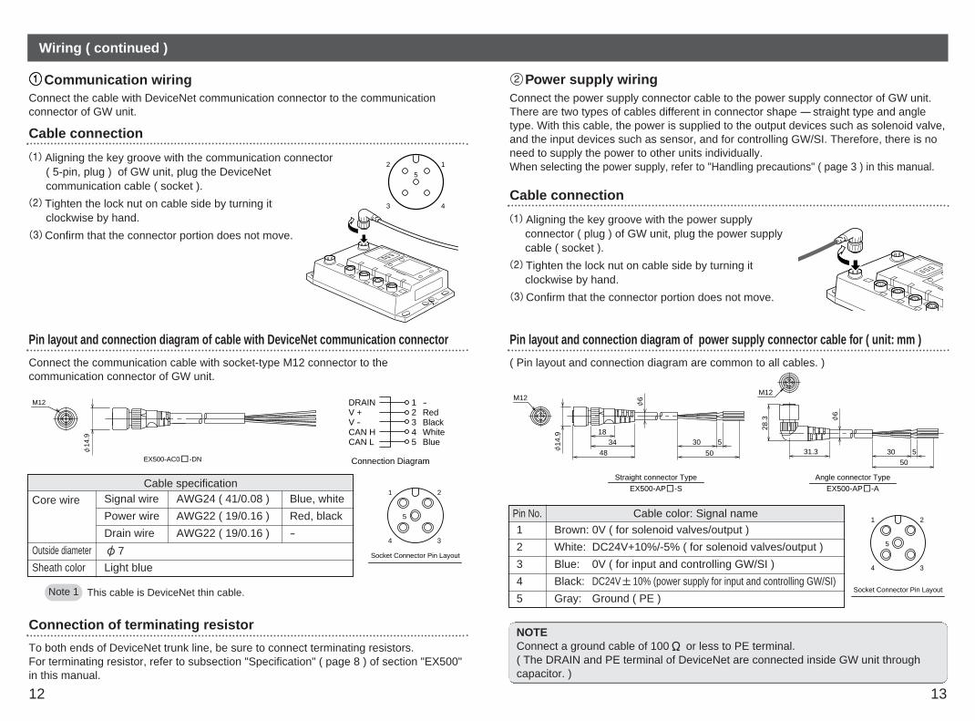
SI Unit Part Names Dimensions ( unit: mm )The SI unit is the unit to communicate with GW unit in combination with manifold valve.It can be used with SV series valves and VQC series valves.In addition, this unit is able to operate solenoid valves, relays. etc. in combination withEX9 series general purpose output block. For how to use it, refer to section "EX9 SeriesGeneral Purpose Output Block" ( page 31 ) in this manual.
SI unit forSV series
1. SI unit for SV series valves ( EX500-S 01 )
SI unit forVQC series( EX500-Q 01 )
2. SI unit for VQC series valves ( EX500-Q )
Communicationconnector "C1" or "0"
1 Connects the branch cable to Input unit ( branch cablewith M12 connector ). ( Note1 )
Communicationconnector "C2" or "1"
2 Connects the branch cable from GW unit ( branchcable with M12 connector ). ( Note1 )
Power LED3 Indicates the power supply status. ( Note2 )
Communication LED4 Indicates the communication status with GW unit: ( Note2 )
NameNo. Application
Common to EX500-S 01/EX500-Q
Note1: For wiring method, refer to subsection "Wiring" ( page 11 ) of section "EX500" in thismanual.
Note2: For display, refer to "Display" ( page 24 ) in section "SI Unit" in this manual.
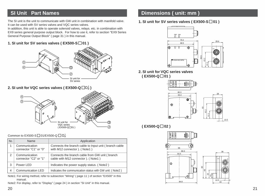
54.5
68.5
79.428.6
22.2
43.2
1. SI unit for SV series valves ( EX500-S 01 )
PW
R
CO
M
64.428
80.3
0
1
10.5
22.2
43.2
60
2. SI unit for VQC series valves( EX500-Q 01 )
0
1
serie
s
10.5
36
66
80.364.4
84.8
22
13
43
60
44
PWR
COM
( EX500-Q 02 )

22 23
Mounting/Wiring SpecificationThe mounting and removing methods of SI unit are as shown below.
For branch wiring method, refer to subsection "Wiring" ( page 11 ) of section "EX500"in this manual. As the power to output devices such as solenoid valve is supplied bybranch wiring ( branch cable with M12 connector ), there is no need to supply powerindividually.
Note 1
For mounting/installation methods of solenoid valve, manifold, etc., refer to thecatalogs, instruction manuals, technical data, etc. of each valve series.When connecting general purpose output block only, refer to subsection "Mounting"( page 33 ) of section "EX9 Series General Purpose Output Block" in this manual.
Note 2
SI Unit for SV Series Valves ( EX500-S 01 )
M3 30: 4 pcs.( Plus-minus slotround head screw )
Supply/exhaust blockassembly
SI Unit for VQC Series Valves ( EX500-Q 01 )
Supply/exhaust blockassembly
M3 10: 2 pcs.( Hexagon socket head cap screw ( with spring washer ))
NOTEHolding with hand so that there will be no gap between SI unit and Air supply/exhaustblock assembly, tighten the bolts. Be sure to tighten each bolt by specified tighteningtorque. ( Tightening torque: 0.6Nm )
1. SI unit for SV series valve ( EX500-S 01 )
Connected block Solenoid valve ( single, double )Relay output module ( 1-point output, 2- point output )
Connected blockstation
Double solenoid valveRelay output module ( 2-point output )
Supply voltage for block DC24V
Supply current for block 0.65A Max.
Current consumption 100mA or less ( at rated voltage )
Single solenoid valveRelay output module ( 1-point output )
Max. 8 stations
Max. 16 stations
Item Specification
2. SI unit for VQC series valve ( EX500-Q )
Connected block Solenoid valve ( single, double )General purpose output block ( EX500-Q 02 only )
Connected blockstation
Supply voltage for block
Supply current for block
Current consumption
Double solenoid valve
Item Specification
3. Applicable valve series
Cassette Tie-rod 40 50 63 80 100 125Series
Manifold Inner diameter of applicable cylinder tube ( mm )
Max. 8 stations
Single solenoid valve
General purpose output block( EX500-Q 02 only )
Max. 16 stations
Max. 8 stations
DC24V
0.75A Max.
100mA or less ( at rated voltage )
SV1000
SV2000
SV3000 -
-
-
-
-
SV4000
VQC1000
VQC2000
VQC4000
For detailed specifications of solenoid valve and manifold, refer to the catalogs, instructionmanuals, technical data, etc. of each valve series.

24 25
Display
Power LED
Communication LED
SI unit for SV series valves ( EX500-S 01 )
Power LED
Communication LED
SI unit for VQC series valves ( EX500-Q )
Power LED Lights on: Power to solenoid valves/output is supplied at thespecified voltage.
Lights off: Power to solenoid valves/output is not supplied atthe specified voltage. ( Voltage dropped to lowerthan 20V. )
CommunicationLED
Lights on: Receiving data from GWLights off: No received data
Display Description
Input Unit Manifold Part Names
Common to EX500-S 01/EX500-Q
The Input unit manifold consists of Input unit, input block (s), end block and DIN rail.The input block up to 8 can be connected ( 16 points ).Any combination of input blocks ( for M8 connector, M12 connector and 8-point-integrated type ) is acceptable.
Input unit1
Note1: For wiring method, refer to subsection "Wiring" ( page 29 ) of section "Input UnitManifold" in this manual.
Note2: For display, refer to "Display" ( page 30 ) in section "Input Unit Manifold" in this manual.
Unit to communicate with GW unit or SI unit.
Communicationconnector
2 To be connected with branch cables from GW unit orSI unit ( branch cable with M12 connector ) ( Note1 )
Power LED3 Indicates the power supply status. ( Note2 )
Input block4 Unit for sensor signal input.
Sensor connector5 Connects with sensor. ( Note1 )
Indicator LED6 Indicates sensor signal status. ( Note2 )
Marker7 To be used for writing input No. etc.
End block8 Composes the end of Input unit manifold.
DIN rail9 To be mounted with Input unit manifold.
Part nameNo. Application
Figure shows the configuration when only input blocks for M8 connector are connected.
Do not mix sensor input specifications ( PNP and NPN ) .Note
26 27
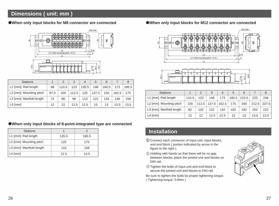
Dimensions ( unit: mm )
When only input blocks for M8 connector are connected
44.2
39.7
L3 (L4)5
L1
L2 ( Rail mounting pitch: 12.5 )
DIN Rail35 49
32.2
(7.5
)
When only input blocks of 8-point-integrated type are connected
L1 [mm]: Rail length
L2 [mm]: Mounting pitch
L3 [mm]: Manifold length
L4 [mm]
98 110.5 123 135.5 148 160.5 173 185.5
87.5 100 112.5 125 137.5 150 162.5 175
74 86 98 110 122 134 146 158
12 12 12.5 12.5 13 13 13.5 13.5
Stations 1 2 3 4 5 6 7 8
L1 [mm]: Rail length
L2 [mm]: Mounting pitch
L3 [mm]: Manifold length
L4 [mm]
135.5 185.5
125 175
110 158
12.5 13.5
Stations 1 2
When only input blocks for M12 connector are connected
(L4)
5
L3
L1
L2 ( Rail mounting pitch: 12.5 )
60
46.9
DIN Rail
44.2
35
32.2
(7.5
)
Connect each connector of Input unit, input blocks,and end block ( portion indicated by arrow in the figure to the right ).
Holding with hands so that there will be no gapbetween blocks, place the jointed unit and blocks onDIN rail.
Tighten the bolts of Input unit and end block tosecure the jointed unit and blocks to DIN rail.
Be sure to tighten the bolts by proper tightening torque.( Tightening torque: 0.6Nm )
Installation
L1 [mm]: Rail length
L2 [mm]: Mounting pitch
L3 [mm]: Manifold length
L4 [mm]
110.5 123 148 173 185.5 210.5 223 248
100 112.5 137.5 162.5 175 200 212.5 237.5
82 102 122 142 162 182 202 222
12 12 12.5 12.5 13 13 13.5 13.5
Stations 1 2 3 4 5 6 7 8

28 29
Specification Wiring
Specifications for Input unit
Connected block Current source type input block ( PNP input block )orCurrent sink type input block ( NPN input block )
Connected block station Max. 8 blocks
Supply voltage for block DC24V
Supply current for block
Current consumption
0.65A Max.
100mA or less ( at rated voltage )
Short circuit protection Operates at 1A Typ. ( Cuts power supply. )Can be reset by returning the power after cutting thepower supply to input and control section of GW unit.
Item Specification
Applicable sensor Current source type( PNP output )
Current sink type( NPN output )
No. of input points 2 points/8 points ( for M8 connector only )
Rated voltage DC24V
Logical "1" input voltage 15V - 26.4V 0V - 8V
Logical "0" input voltage 0V - 5V 19V - 26.4V
Logical "1" input current 5mA Typ. -5mA Typ.
Logical "0" input current 1.5mA
Input delay time 1msec. or less
Indicator LED Green LED
Insulation
Supply current to sensor
N/A
Max. 480mA/Input unit manifold
-1.5mA
Item Specification
Specifications for input block
Branch wiringFor wiring method, refer to subsection "Wiring" ( page 11 ) of section "EX500" in thismanual. To input devices such as sensor, the power is supplied through the branchwiring ( branch cable with M12 connector ). Therefore, there is no need to supply thepower to them individually.
Sensor connector "1"
Sensor connector "0"
M12 Block
1 13 3
4 2
2 4key
key0 1
Input "0" (n) side Input "1" (n+1) side
Input "1" (n+1)
Input "0" (n)
Sensor wiringConnect sensors to the sensorconnectors of input block.
Pin layout of sensor connector
M8 connector ( 3-pin socket ) M12 connector ( 4-pin socket )
Power supply ( DC24V )Power supply ( 0V )Input
Power supply ( DC24V )( Input ) ( Note )Power supply ( 0V )Input
1 2
4 3
1
4 3
Note: Internal wiring of M12 input block and key position for mounting sensor connector
No. 2 pins of M12 input block connectors arewired to each other’s sensor signal input pins( No. 4 pins ) internally.This wiring enables direct input of signals fromtwo points combined into one cable throughconcentric connector etc.When connecting sensors, confirm thespecification of output signal carefully.Otherwise malfunction can result.The key position for mounting sensorconnector is as shown to the right. Considerthis key position when selecting sensor.
NOTEMount a waterproof cap on each unused connector of Input unit. The proper use ofwaterproof cap can achieve IP65 Enclosure. The waterproof caps are deliveredtogether with each input block as accessories. ( Tightening torque: 0.05Nm for M8and 0.1Nm for M12 )

30 31
Wiring (continued ) EX9 Series General Purpose Output Block Part Names
Correspondence between input number and input block
Input block up to 8 can be connected ( 16 points ).Input numbers are 0 - 15 from Input unit side.
00
1
0
1
0
1
0
1
0
1
0
1
0
1
0
1
2 4 6 8 10Input unit 12 14
1 3 5 7 9 11 13 15
Display
Settings for displayPower LED
Indicator LED
Power LED Lights on: Power for input and controlling GW is supplied.Blinks: Under short circuit protection ( abnormal status ).
As the short circuit protective function is operating, thepower is not supplied.
To cancel blinking, turn off and return the power to GW unit.Lights off: Power for input and controlling GW is not supplied.
IndicatorLED
Lights on: Sensor signal input ON ( logical "1" )Lights off: Sensor signal input OFF ( logical "0" )
Display Description
The EX9 series general purpose output block is the unit to operate solenoid valve, relay,etc. in combination with VQC series valve and applicable SI unit.There are two types ---- one type is for low wattage load ( EX9-OET1 or EX9-OET2 ) thatoutputs signals by receiving power supply from SI unit, and the other type is for highwattage load ( EX9-OEP1 or EX9-OEP2 ) that outputs signals by receiving power supplyfrom outside. The type for high wattage load is used in combination with the power block( EX9-PE1 ) connected with external power supply. As the low-wattage-load type ispowered from SI unit, the wattage of load is limited to 1.0W ( Note1 ). For a load up to12W, use the power block and the high-wattage-load type.
Note1: When connected with EX500 series.
1. EX9-OET1/EX9-OET2/EX9-OEP1/EX9-OEP2
VQC series
SI unit forVQC series
( EX500-Q 02 )
Output connector1 Connects with output device. ( Note1 )
Indicator LED 2 Indicates the output status. ( Note2 )
Part nameNo. Application
Note1: For wiring method, refer to subsection "Wiring" ( page 34 ) of section "EX9 SeriesGeneral Purpose Output Block" in this manual.
Note2: For display, refer to subsection "Display" ( page 37 ) of section "EX9 Series GeneralPurpose Output Block" in this manual.

32 33
EX9 Series General Purpose Output Block Part Names (continued ) Mounting
2. EX9-PE1
VQC series
SI unit forgeneral purposeoutput block( EX500-Q 02 )
Dimensions ( unit: mm )
21.259.8
72.6
2126.7
22.2
43.2
1. EX9-OET1/EX9-OET2/EX9-OEP1/EX9-OEP2
21.259.8
80.3
22.2
43.2
21
26.7
PWRPWR
2. EX9-PE1
Power supply connector1 Unused
Power input connector2 Supplies power for output devices. ( Note1 )
Power LED3 Indicates the power supply status. ( Note2 )
Part nameNo. Application
Note1: For wiring method, refer to subsection "Wiring" ( page 34 ) of section "EX9 SeriesGeneral Purpose Output Block" in this manual.
Note2: For display, refer to subsection "Display" ( page 37 ) in section "EX9 Series GeneralPurpose Output Block" in this manual.
M3 18 : 2 pcs.( Hexagon socket head cap screw ( with spring washer ))
Supply/exhaust block assembly, end plate R, power block, or otherEX9 series general purpose output block
Power block or EX9 seriesgeneral purpose output block
Tie-rod: 4 pcs.
SI unit for general purposeoutput block ( EX500-Q 02 )
L dimensions
The mounting and removing methods of each SI unit are as shown below.
NOTEHolding with hand so that there will be no gap between units and tighten the bolts.Be sure to tighten each bolt by specified tightening torque. ( Tightening torque: 0.6Nm )
Dimensions when general purpose output block is connected
0
1
13
0
1
0
1
0
1
0
1
0
1
0
1
0
1
PWR PWR
COM
EX500series
L2L3
L1
Mounting hole for:M4 places
66
1.5
PWR
L1 [mm] 83 104 125 146 167 188 209 230
L2 [mm] 72 93 114 135 156 177 198 219
L3 [mm] 67 88 109 130 151 172 193 214
No. of output block stations 1 2 3 4 5 6 7 8
The above dimensions show those when one unit of power block ( width: 21mm ) iscombined. For details, refer to the instruction manuals, technical data, etc. of EX9series general purpose output block.
Note

34 35
Wiring
Output wiringConnect output devices to the output connectors.
EX9-OET1/EX9-OET2/EX9-OEP1/EX9-OEP2 output connectors
M12, 5-pin, socketConnector on cable side: Ex; OMRON Corp.,
XS2H, XS2G. etc., and Franz Binder GmbH, Series 713 and 763.
NOTEMount a waterproof cap to each unused connector. The proper use of waterproof capcan achieve IP65 Enclosure. ( Tightening torque for M12: 0.1Nm )
2
4 3
5
1
1
Output connectorNo.0
Output connectorNo.1
Output connectorNo.0
Output connectorNo.1
Model No.
Pin No.
EX9-OET2/EX9-OEP2 EX9-OET1/EX9-OEP1
NPN output
Power supply( DC24V )
Power supply( DC24V )
NC NC
2 Output ( OUT1 ) NC Output ( OUT 1 ) NC
3 NC NC Power supply( GND )
Power supply( GND )
4 Output ( OUT 0 ) Output ( OUT 1 ) Output ( OUT 0 ) Output ( OUT 1 )
5 NC NC NC NC
PNP output
NC: Not connectedTwo outputs are available with only output connector No. 0.
M12, 5-pin, reverse key, socket
Power supply wiringWhen combining EX9-OEP1 ( or EX9-OEP2 ) and EX9-PE1 and using external powersupply, connect the power supply to the power input connector of EX9-PE1.When selecting power supply, refer to "Handling precautions" ( page 3 ) in this manual.
EX9-PE1 power supply connector No.0
M12, 5-pin, reverse key, plugCable side: Hans Turck GmbH & Co., WAKW series
EX9-PE1 power input connector No.1
Note: Each signal of connector No.0 is connected to corresponding signal of connector No.1.The pins whose applications are shown in brackets [ ], are prepared supplementarily andnot used normally.
25
3
1
4
15
4
2
3
Power supplyconnector No.0
Power inputconnector No.1
43
25.5
14
1
4
25
3
M12
1
Pin No. Power input connector No.1 Power supply connector No.0
Power supply for output devices ( DC24V ) Power supply for output devices ( DC24V )
2 Power supply for output devices ( 0V ) [Power supply for output devices ( 0V ) ]
3
4
5
[Power supply for sensor ( DC24V ) ]
[Power supply for sensor ( 0V ) ]
Ground
[Power supply for sensor ( DC24V ) ]
[Power supply for sensor ( 0V ) ]
[Ground]
Keep the waterproof cap mounted on power supply connector No.0 while usingEX9-PE1. This connector is prepared supplementarily and not used normally.
Note

36 37
Specification Display
1. EX9-OET1/EX9-OET2/ EX9-OEP1/EX9-OEP2
No. of outputpoints 2 points/unit
Outputmethod
N-ch MOS-FET( open drain )
Insulationmethod Optical isolation ( with SI unit ) Optical isolation ( with this unit )
( Note )
Item
Model No.
Specification
EX9-OEP2
P-ch MOS-FET( open drain )
EX9-OEP1
N-ch MOS-FET( open drain )
EX9-OET2
P-ch MOS-FET( open drain )
EX9-OET1
Note: To be used in combination with EX9-PE1.For detailed specifications, refer to the instruction manuals, technical data, etc. of EX9series general purpose output block.
Rated voltage DC24V+10%, -5%
Supply current 3A Max.
Item Specification
2. EX9-PE1
1. EX9-OET1/EX9-OET2/EX9-OEP1/EX9-OEP2
Settings for display
0 Lights on: Output ( OUT 0 ) is ON.Lights off: Output ( OUT 0 ) is OFF.
1 Lights on: Output ( OUT 1 ) is ON.Lights off: Output ( OUT 1 ) is OFF.
Display Description
PWRPWR
2. EX9-PE1
PWR Lights on: Power is supplied from external powersupply.
Lights off: Power is not supplied from externalpower supply.
Display Description

38 39
Branch cable with M12 connectorFor details, refer to subsection "Wiring" ( page 11 ) in section "EX500" in this manual.
EX500-AC 030 - SSPSHow to order
Cable length (L) Connector specification003 0.3 [m]005 0.5 [m]010 1 [m]030 3 [m]050 5 [m]
SSPS Socket side: Straight, Plug side: StraightSAPA Socket side: Angle, Plug side: Angle
NOTETighten the waterproof cap by the specified tightening torque. ( 0.05Nm for M8,0.1Nm for M12 )
Power supply connector cableFor details, refer to subsection "Wiring" ( page 11 ) of section "EX500" in this manual.
EX500-AP 050 - SHow to order
Cable length (L) Connector specification010 1 [m]050 5 [m]
S StraightA Angle
Terminal PlugConnected to C1 ( or 0 ) of SI unit when Input unit manifold is unused. ( If this terminal plugis not used, COM LED of GW unit does not light on. )
EX500-AC000-SHow to order
1
7
65
4
3
28M12
16
44.7Plug Connector Pin Layout
Waterproof capMounted on unused ports of GW unit, input block, power block and output block.The proper use of this waterproof cap can achieve IP65 Enclosure. ( The waterproof capsare delivered together with each input block as accessories. )
EX500-AWHow to order
Connector specificationES M8 connector ( socket ) /10 pcs.TP M12 connector ( plug ) /1 pc.TS M12 connector ( socket ) /10 pcs.
Option
Cable with DeviceNet communication connectorFor details, refer to subsection "Wiring" ( page 11 ) in section "EX500" in this manual.
EX500-AC 050 - DNHow to order
Cable length (L)010 1 [m]050 5 [m]

40 41
Troubleshooting
Solenoid valvedoesn't work
Solenoid valve doesn'twork as programmed
1
2
Check the power for solenoid valves/output ( DC24V )is supplied. Check the connection of the branch cable with M12connector to SI unit.Check Power LED and Communication LEDs of SIunit light on.
Check the wiring specification for manifold blockassembly and modify the program.
Power LED of Input unit is blinking
3 Short circuit of input sensor due to failure etc. ispossibly caused. Check the sensor.A current larger than specified value is flowingthrough the power line for input and controllingGW/SI. Check the power supply section.
No signal is input eventhough connected withsensor(s)
4 Check the power for input and controlling GW/SI( DC24V ) is supplied.Check indicator LED of each block lights on.
COM A - D LEDdoesn't light on
5 Check Input unit is connected to the branch of unlitCOM port, and the branch cable with M12 connectoris connected to the Input unit.When connecting no Input unit, connect a terminalplug.
ItemNo. Solution/Corrective action
MS LED statusNormal status: Lit in greenFatal failure: Lit in red
1 Check the signal line from PLC isconnected.Check the wiring and pin Nos.Check the data rate and addresssettings.
NS LED statusOffline/Power is OFF: UnlitOnline/Communication is not established:Blinking in greenOnline/Communication is established: Lit in greenMinor communication error occurred:Blinking in redFatal communication error occurred: Lit in red
2 Check the signal line from PLC isconnected.Check the wiring and pin Nos.Check the data rate and addresssetting.
SOL LED is unlit3 Check the power for solenoidvalves/output (DC24V) is supplied.Check the power supply voltage forsolenoid valves/output doesn't dropunder 20V.
ItemNo. Solution/Corrective action
Overall system DeviceNet compatible communication