Embed Size (px)
Citation preview

URLhttp://www.smcworld.com
Reduced wiring systemDeviceNet Compatible GW unit
Operation ManualEX510-GDN1
SAFETY 2
Product Summary 7
Name of Parts / Accessories 8
Dimensions 9
Settings 10
Specifications 12
Wiring 13
Display/ Switch Setting 20
Troubleshooting 24
Table of ContentsThank you for purchasing the SMC reduced wiring system EX510series.Please read this manual carefully before operating the digitalpressure switch and make sure you understand the digitalpressure switch, its capabilities and limitations.Please keep this manual handy for future reference.
OPERATOR•This operation manual has been written for those who haveknowledge of machinery and apparatuses that use reducedwiring units and have full knowledge of assembly, operationand maintenance of such equipment.
•Please read this operation manual carefully and understand itbefore assembling, operating or providing maintenance serviceto the actuator.
PhoneAUSTRIA / (43) 2262-62 280 ITALY / (39) 02-92711BELGIUM / (32) 3-355 1464 NETHERLANDS / (31) 20-531 8888 CZECH REP. / (420) 5-414 24611 NORWAY / (47) 67 12 90 20DENMARK / (45) 70 25 29 00 POLAND / (48) 22-548 50 85FINLAND / (358) 9-859 580 PORTUGAL / (351) 2 610 89 22FRANCE / (33) 1-64 76 1000 SPAIN / (34) 945-18 4100GERMANY / (49) 6103 4020 SWEDEN / (46) 8-603 0700GREECE / (30) 1- 342 6076 SWITZERLAND / (41) 52-396 3131HUNGARY / (36) 1-371 1343 TURKEY / (90) 212 221 1512IRELAND / (353) 1-403 9000 UNITED KINGDOM / (44) 1908-56 3888

32
SAFETY
Do not operate beyond specification range.Fire, malfunction or damage can result.Only use the unit after confirming the specification.
Do not use the product in the environment with possiblepresence of flammable, explosive or corrosive gas with theproduct.Fire, explosion or corrosion can result. This unit does not have anexplosion proof construction.
Do not disassemble, modify (including change of printedcircuit board) or repair.An injury or failure can result.
These instructions must be followed when using theproduct in an interlocking circuit:• Provide double interlocking by another system such asmechanical protection
• Check the product regularly to ensure proper operationOtherwise a malfunction can cause an accident.
These instructions must be followed while carrying outmaintenance work:• Turn off the power supply • Stop the supplied air, exhaust the residual pressure andverify the release of air before performing maintenance
Otherwise it can cause injury.
This manual contains essential information for the protection ofusers and others from possible injury and property damage. Toensure correct handling, please follow the instructions.Please check that you fully understand the meaning of thefollowing messages (signs) before going on to read the text, andalways follow the instructions.Please read the operation manuals of related apparatus andunderstand it before operating the unit.
Read this manual and follow its instructions. Titles such asWARNING, CAUTION and NOTE, will be followed byimportant safety information which must be carefully followed.
IMPORTANT MESSAGES
Indicates a potentially hazardous situationwhich could result in death or seriousinjury if you do not follow instructions.
Gives you helpful information.
Indicates a potentially hazardoussituation which if not avoided, may resultin minor injury or moderate injury.

5
NoteThe direct-current power supply should be a UL approved powersupply.1. Limited voltage current circuit in accordance with UL508.
A circuit which power is supplied by the secondary coil of atransformer that meets the following conditions.
• Maximum voltage (with no load): less than 30Vrms (42.4V peak) • Maximum current :(1)less than 8A(including when short circuited)
(2)limited by circuit protector (such as fuse)with the following ratings.
2. A circuit using max. 30 Vrms or less (Class-2 circuit), whichpower is supplied by Class-2 power supply unit in accordancewith UL1310 or Class-2 power supply unit in accordance withUL1585.
Follow the instructions given below when handling your unit.Failure to follow instructions may damage the unit.• Operate the unit within the specified voltage range.• Leave space around the unit for maintenance.• Do not remove labels.• Do not drop, hit or apply excessive shock to the unit.• Follow the specified tightening torque.• Do not bend or apply tensile force to cables, or apply force by
placing heavy load on them.• Connect wires and cables correctly.• Do not connect wires while the power is on.
No load voltage (V peak)
0 to 20 [V]
Above 20 to 30 [V]
Max. current rating (A)
5.0
100/peak voltage
4
SAFETY (continue)
Execute a performance inspection after completing themaintenance check. Please do not use if there is any error.There is a possibility that safety cannot be secured due to themalfunction not intended.
Provide grounding for correct operation and improvednoise resistance of the unit.The unit should be individually grounded with a short cable.

76
Product Summary
System structure
Power supply for output
Power supply for input and controlling GW
24VDC
24VDC GW unit
Input unit(e-con 8 pcs type)
Input unit (e-con 16 pcs type)(connecting to 4 set maximum)
Branch cable(EX510-FC )
Valve manifold with SI unit (connecting to 4 set maximum)
Connecting to busat upper level (DeviceNet)
• Do not lay wires or cables with power cable or high-voltagecable in the same wiring route.
• Verify the insulation of wiring.• Take proper measurements against noise such as noise filter
when the unit is incorporated in equipment or devices.• Select the proper type of protection according to the environment
of operation.• Take sufficient shielding measures when installing at a following
place.(1) A place where noise due to static electricity is generated(2) A place where electric field strength is high(3) A place where there is radioactive irradiation(4) A place near power line
• Do not use the product close to a place where electric surgesare generated.
• Use a unit equipped with surge absorber when a surge-generating load such as a solenoid valve is driven directly.
• Prevent foreign matter such as remnant of wires from enteringthis product.
• Do not expose the unit to vibration and impact.• Keep the specified ambient temperature range.• Do not expose the unit to heat radiation from a heat source
located nearby.• Use a precision screwdriver with small flat blade when setting
DIP switch.• Perform maintenance and check regularly.• Perform a proper functional check.• Do not clean the product with chemicals such as benzene and
thinner.
SAFETY (continue)
The GW unit connects to the installation using the DeviceNetfieldbus standard. The input/output modules are addressed fromDeviceNet via the GW unit.

98 9
Dimension (in mm)
6425.7
COM A
COM B
COM C
COM D
OUTPUTINPUT
60
80
16
PWR(V)
PWR
BUS
Name of Parts / Accessories
Communicationconnector for DeviceNet (1pc)
Power supplyconnector(2 pcs)
Accessory
1
342
5
6
78
9 1011
No. Parts Purpose
1Communicationsocket (BUS)
Connect to DeviceNet line with an accessoryconnector for DeviceNet ( ). *
2Power supplysocket (PWR(V))
Supplying power for output instrumentssuch as a solenoid valve with an accessoryconnector ( ). *
3Power supplysocket (PWR)
Supplying power for controlling GW and forinput instruments such as a sensor with anaccessory connector ( ). *
4GW unit side branchconnector (for input)
Connecting an input unit etc. by usingbranch cables (EX510-FC )
5GW unit side branchconnector (for output)
Connecting SI unit (manifold valve) etc. byusing branch cables (EX510-FC )
6 PE terminal Used for grounding
7 Mounting hole Used when a unit is mounted with 2 M4 screws.
8 DIN rail mounting slot Used when a unit is mounted to DIN rail.
9Display/ settingswitch area
Setting switch such as LED display of unitstate, MAC ID, Baud rate and I/O point.
*Note: For wiring method, see "Wring" in the "Technical Specifications".

1110
RemovalMounting
Claw 1
Claw 2
Put Claw 1 of the body under DIN rail and push it upward. Pushdown Claw 2 to the opposite rail until the claw clicks securely onto rail.(Mounting procedure and )For removing, lever up the DIN rail fixing plate of the body with aflat blade screwdriver, and remove it by tilting Claw 2 side forward.(Removal procedure and )
Settings
DIN rail installation
DIN rail
Perspective drawing (tolerance 0.2)
Screw installation
2-M4
Tightening torque : 0.8N m
PWR(V)
PWR
BUS
16
PWR(V)
PWR
BUS
OUTPUTINPUT
705
54 5

1312
Power supply for output
Power supplyfor input and
controlling GW
(Brown)
Internal circuit
DC-DCconverter(isolated)
V-CAN_LDrain
CAN_HV+
CO
M A
+24V0V
PE
+24VTD+TD-0V+24VRD+RD-0V
CO
M D
+24VTD+TD-0V
+24VRD+RD-0V
+24V0V
OU
TP
UT
INP
UT
OU
TP
UT
INP
UT
DC-DCconverter
(uninsulation)
CANTransceiver
Communicationpart isolated
circuit(Photo-coupler)
Specifications
Basic specifications
Compatible system
Slave type
DeviceNet Release 2.0
Group2 Only Server
MAC ID setting 0 to 63
Rated voltage
Range ofpower supplyvoltage
24VDC
Power supply for input and controlling GW : 24VDC 10%Power supply for output:24VDC+10%/-5%(Warning for voltage drop is given at approx. 20V)Power supply for DeviceNet : 11 to 25VDC
Rated current
Input/ outputpoint
Power supply for input and controlling GW : 4.1A(Inside GW unit: 0.1A, input unit: 4A)Current for output: 6APower supply for DeviceNet : 50mA
Input point: Max. 64 / Output point: max. 64(Changeable by switch settings)
Bus for upper level Wiring
Internal circuit
Baud rate
Thin cable
125kbps
500m or lessThick cable
100m or less
250kbps
250m or less 100m or less
500kbps
Max. lengthof Network
156m or less
Note: Max. extended cable length is 6m.
78m or less 39m or lessTotal extended cablelength
Number of branches forinput/ output
4 branches for input4 branches for output
Communication typeCommunication protocol: dedicated for SMCBaud rate : 750kbps
Lower level bus
Max. 1A per branch
Branch current for output Max. 1.5A per branch
Branch cable lengthAt 0.75A per branch : 20m or lessAt 1.0A per branch : 16m or lessAt 1.5A per branch : 10m or less
Branch current for input
Device informationVender code : 7 (SMC Corp.)Product type : 12Product code : 100
Applicable messageDuplicate MAC ID Check MessageGroup2 Only Unconnected Explicit MessageExplicit Message, Poll/ I/O Message
I/O message sizeInput: Max. 8byte, Output: Max. 8byte(Changeable by switch settings)

1514
Branch cable wiringThe wiring between each unit should use branch cables, and beconnected with branch connectors.The SI unit and input unit have 2 branch connectors each.
Pressure welding for branch connectorThe method of pressure assembly of the branch connector isexplained.
(1) Components
Pin no.display
Insulating cap
Cover
Body
Branch cable
Brown BlackWhite
Blue
(2) Working procedureSet a branch cable in the cover.
1)Set the brown wire of the branchcable so that it matches to pin #1.
2)Push the 4cable ends securelyagainst insulating cap in cover.
Wiring (continue)
Pin #1: Brown wire
Hole for fixing latch
Latch Pin #1: Brown wire
Tentative fixing to the bodyFit 4 latches on the body to 4ditches on the cover, and pressthem until the latch engages tothe level 1.
Press fittingPress the cover to thebody with suitable priers.
EX510
4321
4 branches for input
4 branches for output
Branch cable
To SI unit
To Input unit
Branch connector at GW unit side
Branch connector at cable side
COM D
COM C
COM B
COM A
Wiring of branch cables
Insert branch connector on the table side from the bottom (COMA, B, C, D of branch connector of GW unit side).
Note) Check the color of the wires printed on the branch connectorand the color of the cables are the same.
3)Fold the cover so that thebranch cable is trappedbetween the cover.
4)Fix the latch t ip byinserting through the holefor the fixing latch.
ConfirmationCheck that all of the 4 latchesare fully engaged.

17
Black Blue White RedDrain
Black Blue White RedDrain
V- CAN_L DrainCAN_H V+
Terminating resistor
Black Blue White RedDrain
V- CAN_L DrainCAN_H V+
Communication connectorfor DeviceNet
Drawing1
Drawing2
Drawing3
16
Wiring (continue)
Communication wiringConnect DeviceNet dedicated cables to the communicationconnector for DeviceNet.(1)Make sure to connect the signal cables to designated pins
(Refer to Drawing 1). And tighten the connector surely to 0.5 to0.6Nm tightening torque.
(3)Refer to Drawing 3 about how to connect to the unit.
(2)Make sure to connect a "terminating resistor" between"CAN_H"-"CAN_L" to the units at both ends of the system.(Refer to Drawing 2).
Terminating resistor :121 1%, 1/4W
1918
Wiring (continue)
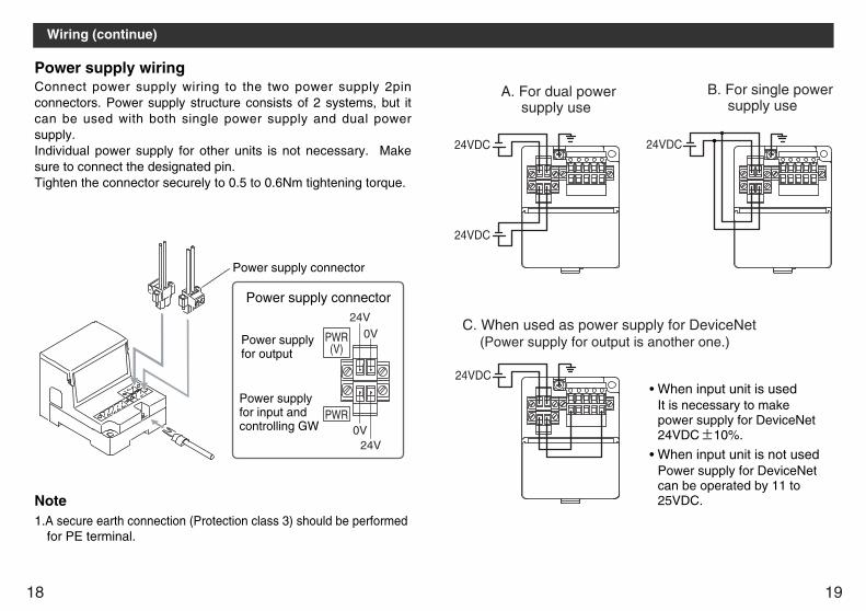
Power supply wiringConnect power supply wiring to the two power supply 2pinconnectors. Power supply structure consists of 2 systems, but itcan be used with both single power supply and dual powersupply.Individual power supply for other units is not necessary. Makesure to connect the designated pin.Tighten the connector securely to 0.5 to 0.6Nm tightening torque.
Power supply connector
Power supplyfor output
Power supplyfor input andcontrolling GW
Power supply connector
PWR(V)
PWR
0V
24V
24V
0V
1.A secure earth connection (Protection class 3) should be performedfor PE terminal.
Note
24VDC
24VDC
A. For dual power supply use
24VDC
B. For single power supply use
24VDC
C. When used as power supply for DeviceNet (Power supply for output is another one.)
• When input unit is usedIt is necessary to makepower supply for DeviceNet24VDC 10%.
• When input unit is not usedPower supply for DeviceNetcan be operated by 11 to25VDC.

2120
MAC ID setting (switch No.1 to 6)All of the settings when shipped from plant are turned ON and thestation number is set 63. Make sure to set the station number inthe range of 0 to 63.
10987654321
32168421
ON
SW1OFF
ON
MAC ID Baud rateHOLD/CLRHW/SW
Switch settingMake sure that switch setting is done with power supply turned off.Open the cover, and set DIP switch with a small flat bladescrewdriver, etc.
Setting of MAC ID, Baud rate, HOLD/CLR, HW/SWmode (SW1)These setting are done with SW1.
Display / Switch Setting
SW1OFFON
OFFON
COM C COM DCOM A COM B
SW2
MNSPWR(V) PWR
Setting for Display
Display Meaning
PWR(V)
The power for output is supplied with specified voltage :LightsThe power for output is not supplied with specified voltage:Lights off
PWRPower supply for DeviceNet is supplied : LightsPower supply for DeviceNet is not supplied : Lights off
MNS
Power off, off line, or duplicate check MAC ID : Lights offWaiting for I/O connection (online) : Green flashingI/O connection completed (online) : Green lightsI/O connection • time out : Red flashing(Light degree of communication error)MAC ID duplicate error, or BUS OFF error : Red lights(Heavy degree of communication error)
COM ACOM A is receiving data : Lights. *COM A is having no data to receive : Lights off
COM BCOM B is receiving data : Lights. *COM B is having no data to receive : Lights off
COM CCOM C is receiving data : Lights. *COM C is having no data to receive : Lights off
COM DCOM D is receiving data : Lights. *COM D is having no data to receive : Lights off
*Note:It is lit when input unit is connected and communicating normally.
1(No.1)
0
MAC ID
1
2
3
:
10
11
:
62
63
2(No.2) 4(No.3) 8(No.4) 16(No.5) 32(No.6)
OFF OFF OFF OFF OFF OFF
ON OFF OFF OFF OFF OFF
OFF ON OFF OFF OFF OFF
ON ON OFF OFF OFF OFF
: : : : : :
OFF ON OFF ON OFF OFF
ON ON OFF ON OFF OFF
: : : : : :
OFF ON ON ON ON ON
ON ON ON ON ON ON

2322
Input setting (switch No. 1 to 3), Output setting (switchNo. 4 to 6)The setting is as follows. All of the settings when shipped fromplant are turned OFF, 64 I/O points.
Input/Output Setting (SW2)Input/output Setting is done with SW2.
Display/ Switch Setting (continue)
Baud rate setting (switch No. 7 to 8)Make sure to set the baud rate in the range as follows. All of thesettings when shipped from plant are turned OFF, set to 125kbps.
HOLD/CLR setting (switch No. 9)The setting is as follows.The setting when shipped from plant is turned OFF, set to CLR.
Baud rate
125kbps
250kbps
500kbps
-
No.7
OFF
ON
OFF
ON
No.8
OFF
OFF
ON
ON
HOLD/CLR
CLR
Function
Output is cleared when an error occurs.
HOLD Output is held when an error occurs.
No.9
OFF
ON
Mode
H W
Function
Set MAC ID and baud rate with SW1 to 8.
SWMAC ID and baud rate are set by network.Note: SW1 to 8 are ignored.
No.10
OFF
ON
654321ON
SW2OFF
ON
Number of Input settingNumber of Output setting
No.1 No.2 No.3 Input point COM A COM BOFF OFF 64 16 16OFF OFF 0 - -OFF ON 16 8 8OFF ON 16 16 -ON OFF 32 8 8ON OFF 32 16 16ON ONON ON
Reserve
COM C COM D16 16- -- -- -8 8- -
OFFONOFFONOFFONOFFONHW/SW mode setting (switch No. 10)
The setting is as follows.The setting when shipped from plant is turned OFF,set to HWmode.
No.4 No.5 No.6 Output point COM A COM BOFF OFF 64 16 16OFF OFF 0 - -OFF ON 16 8 8OFF ON 16 16 -ON OFF 32 8 8ON OFF 32 16 16ON ONON ON
Reserve
COM C COM D16 16- -- -- -8 8- -
OFFONOFFONOFFONOFFON

2524
DeviceNet compatible communicationNo.
1
2
3
Item
PWR LED is UNLIT
PWR(V) LED is UNLIT
The status of MNS LEDNot online : Light offOnline, not allocated :
Green flashingOnline, allocated : Green lightLight degree of communicationerror : Red flashingHeavy degree of communicationerror : Red light
Remedy / Disposal
•Check the power supply forDeviceNet is supplied.
•Check the power for output(24VDC) is supplied.
•Check the power supplyvoltage for output is above20V.
•Check the power for inputand controlling GW (24VDC) is supplied.
•Check the signal line fromPLC is correctly connected.
•Check the wiring and pinnumbers.
•Check the baud rate andMAC ID setting is correct.
Troubleshooting
1
2
3
Remedy / Disposal
•Check the power for output (24VDC) issupplied.
•Check the branch cable is connected toSI unit.
•Check the LED for power supply (PWR)and the LED for communication (COM) atSI unit are ON.
•Ensure output branch current does notexceed the specification range.
•Program it after checking the wiringspecification of manifold block assembly.
•Check the power for input and controllingGW (24VDC) is supplied.
•Check the input unit indication LED is ON.•Ensure input branch current does notexceed the specification range.
•Check the connection of UNLIT COMport branch to input unit.
4COM A-D isnot LIT
Signals cannotbe receivedeven with asensor
Solenoid valveis not working
Valve is notworking asprogram directs
No. Item
Overall system
![EX510-SQ info de - SMC · L1 47.5 58 11.5 26.4 13 29.5 108.5 [monostabil, bistabiles Impulsventil] 49.5 (108.5) 58 43.5 37 26 mit Anschluss oben Ausgang ... Chiyoda-ku, Tokyo 101-0021,](https://img.pdfslide.net/doc/110x75/5ec4283c7b922015155d86cd/ex510-sq-info-de-smc-l1-475-58-115-264-13-295-1085-monostabil-bistabiles.jpg)