Embed Size (px)
Citation preview

User's manual
Retain for future use
Altivar 71
DeviceNet card
VW3 A3 309

2
Contents
Before you begin_____________________________________________________________________________________________ 3
Documentation structure_______________________________________________________________________________________ 4
Introduction_________________________________________________________________________________________________ 5Presentation _____________________________________________________________________________________________ 5Notation ________________________________________________________________________________________________ 5
Quick start__________________________________________________________________________________________________ 6
Hardware setup _____________________________________________________________________________________________ 7Receipt _________________________________________________________________________________________________ 7Hardware description ______________________________________________________________________________________ 7Installing the card in the drive________________________________________________________________________________ 7Coding the switches _______________________________________________________________________________________ 8
Wiring to the network ________________________________________________________________________________________ 10Cable routing practices____________________________________________________________________________________ 10Wiring the DeviceNet connector _____________________________________________________________________________ 10
Configuring by the drive HMI __________________________________________________________________________________ 12Configuring the control ____________________________________________________________________________________ 12Configuring the communication scanner ______________________________________________________________________ 17Configuring the fault management ___________________________________________________________________________ 19Configuring monitored parameters ___________________________________________________________________________ 20
Configuring by a network tool __________________________________________________________________________________ 21Network tool ____________________________________________________________________________________________ 21Going online with RSNetWorx ______________________________________________________________________________ 21Creating an EDS file ______________________________________________________________________________________ 21Configuring the DeviceNet scanner __________________________________________________________________________ 22Editing parameters of the drive______________________________________________________________________________ 27Editing objects of the drive _________________________________________________________________________________ 32
Creating a PLC program______________________________________________________________________________________ 35Using I/O messaging _____________________________________________________________________________________ 35Using explicit messaging __________________________________________________________________________________ 35
Diagnostics by the drive HMI __________________________________________________________________________________ 36Checking the node address and the data rate __________________________________________________________________ 36Signalling LED __________________________________________________________________________________________ 37Monitoring the control _____________________________________________________________________________________ 38Monitoring the communication scanner _______________________________________________________________________ 39Troubleshooting the communication fault______________________________________________________________________ 40Troubleshooting the card fault ______________________________________________________________________________ 41
DeviceNet objects___________________________________________________________________________________________ 42Supported classes _______________________________________________________________________________________ 42Identity object ___________________________________________________________________________________________ 43Message router object ____________________________________________________________________________________ 46DeviceNet object_________________________________________________________________________________________ 47Assembly object _________________________________________________________________________________________ 49Connection object________________________________________________________________________________________ 60Motor data object ________________________________________________________________________________________ 64Control supervisor object __________________________________________________________________________________ 65AC/DC Drive Object ______________________________________________________________________________________ 67Acknowledge handler object________________________________________________________________________________ 68Application objects _______________________________________________________________________________________ 69DeviceNet interface object _________________________________________________________________________________ 70
While every precaution has been taken in the preparation of this document, SchneiderElectric SA assumes no liability for any omissions or errors it may contain, nor for anydamages resulting from the application or use of the information herein.
The products described in this document may be changed or modified at any time,either from a technical point of view or in the way they are operated. Their descriptioncan in no way be considered contractual.

1. Before you begin
Read and understand these instructions before performing any procedure with this drive.
DANGERHAZARDOUS VOLTAGE• Read and understand the Installation Manual before installing or operating the Altivar 71 drive. Installation, adjustment,
repair, and maintenance must be performed by qualified personnel.
• The user is responsible for compliance with all international and national electrical standards in force concerning protective grounding of all equipment.
• Many parts of this variable speed drive, including the printed circuit cards, operate at the line voltage. DO NOT TOUCH.Use only electrically insulated tools.
• DO NOT touch unshielded components or terminal strip screw connections with voltage present.
• DO NOT short across terminals PA and PC or across the DC bus capacitors.
• Install and close all the covers before applying power or starting and stopping the drive.
• Before servicing the variable speed drive- Disconnect all power.- Place a “DO NOT TURN ON” label on the variable speed drive disconnect.- Lock the disconnect in the open position.
• Disconnect all power including external control power that may be present before servicing the drive. WAIT 15 MINUTES to allow the DC bus capacitors to discharge. Then follow the DC bus voltage measurement procedure given in the Installation Manual to verify that the DC voltage is less than 45 VDC. The drive LEDs are not accurate indicators of the absence of DC bus voltage.
Electric shock will result in death or serious injury.
CAUTION
DAMAGED EQUIPMENTDo not install or operate any drive that appears damaged.Failure to follow this instruction can result in equipment damage.
3

2. Documentation structure
The following Altivar 71 technical documents are available on the Web site www.telemecanique.com and on the CDROM delivered witheach drive.
b Installation manualThis manual describes:• How to assemble the drive• How to connect the drive
b Programming manualThis manual describes:• The functions• The parameters• How to use the drive HMI (integrated HMI and graphic HMI)
b Communication parameters manualThis manual describes:• The drive parameters with specific information (addresses, formats, etc.) for use via a bus or communication network• The operating modes specific to communication (state chart)• The interaction between communication and local control
b Modbus, CANopen, Ethernet, Profibus, INTERBUS, Uni-Telway, DeviceNet, Modbus Plus, Fipio, etc., manualsThese manuals describe:• Connection to the bus or network• Configuration of the communication-specific parameters via the integrated HMI or the graphic HMI• Diagnostics• Software setup• The communication services specific to the protocol
b Altivar 58/58F migration manualThis manual describes the differences between the Altivar 71 and the Altivar 58/58F.It explains how to replace an Altivar 58 or 58F, including how to replace drives communicating on a bus or network.
4

3. Introduction
3. 1. PresentationThe DeviceNet communication card (catalog number VW3 A3 309) is used to connect an Altivar 71 drive to a DeviceNet network.
The communication card has an open-style 5-pin connector for connection to the network.
Data exchanges give access to all Altivar 71 functions:• Downloading configuration and adjustment parameters,• Command,• Monitoring,• Diagnostics.
DeviceNet cables and connecting accessories must be ordered separately.
The graphic display terminal or the integrated display terminal can be used to access numerous functions for communication diagnostics.
3. 2. NotationDrive terminal displaysThe graphic display terminal menus are shown in square brackets.Example: [1.9 COMMUNICATION].
The integrated 7-segment display terminal menus are shown in round brackets.Example: (COM-).
Parameter names are displayed on the graphic display terminal in square brackets.Example: [Fallback speed]
Parameter codes are displayed on the integrated 7-segment display terminal in round brackets.Example: (LFF).
FormatsHexadecimal values are written as follows: 16#Binary values are written as follows: 2#
VocabularyDepending on DeviceNet document and tools, equivalent wordings are used. The table below shows vocabulary used in the presentdocument and other corresponding definitions.
The reader should avoid mixing two terms:- DeviceNet scanner, which is the master device on the DeviceNet network.- Communication scanner, which is a function inside the Altivar drive.
AbbreviationsReq. = RequiredOpt. = Optional
In this document Other CommentsNode address DeviceNet address, MAC IDData rate Baud ratekbit/s kBPS, kbps, kSetpoint Reference, targetPath Object Address Class, instance, attribute
5

4. Quick start
This section is provided to help experienced users quickly start using the DeviceNet card. If you are unsure how to complete a step, referto the referenced chapter.
Step Refer to1 Review the safety precautions for the Altivar drive and DeviceNet card. Installation manual2 Verify that the Altivar drive is properly installed. Installation manual4 Install the DeviceNet card in the drive.
Verify that the Altivar drive is not powered.Then, dismount the drive cover, mount the card in the drive. Finally mount the cover.
Installation manual
4 Commission the DeviceNet card.Verify that the Altivar drive is not powered.Set a unique node address and the appropriate data rate using the switches on the card.If desired, you can disable the switches and use parameter settings instead.
5. Hardware setup
5 Connect the drive to the DeviceNet network.Verify that the Altivar drive is not powered.Then, connect the card to the network using a DeviceNet cable.
6. Wiring to the network
6 Apply power to the drive.The card receives power from the drive.Apply power to the drive.The status indicator should be green.If it flashes red, there is a problem (refer to 10. 2. Signalling LED).
10. Diagnostics by the drive HMI
7 Configure the drive for your application.Select the functions and set the parameters as required by your application.
Programming manual
8 Configure the drive behaviour and I/O interface for DeviceNet by the drive HMI.Choose the suitable assemblies for your application (refer to 7. 1. Configuring the control).
If assemblies 100 or 101 are used, select the commands assigned to the control word (referthe Programming manual).
Set the parameters for the following features as requiredby your application: Control and setpoint channels (refer to 7. 1. Configuring the control), If assemblies 100 or 101 are used, input and output assignments
(refer to 7. 2. Configuring the communication scanner), Behaviour on communication fault (refer to 7. 3. Configuring the fault management), The parameters that you would like to monitor by the drive HMI for diagnostics
(refer to 7. 4. Configuring monitored parameters).
Programming manualCommunication parameters manual7. Configuring by the drive HMI
9 Apply power to the DeviceNet master and other devices on the network.Verify that the master and network are installed and functioning in accordance with DeviceNetstandards, and then apply power to them.
DeviceNet master manuals(DeviceNet cable system planningand Installation manual ...)
10 Configure the scanner to communicate with the drive.Use a network tool such as RSNetWorx for DeviceNet to configure the scanner on the network.Make sure to:
Set up the scan list, Map the drive data to the scan list, Save your DeviceNet configuration to the scanner and a file.
8. 4. Configuring the DeviceNet scanner
11 Configure the drive by the network tool.Set the parameters for the following features as required by your application:
If the data rate switches (7 and 8) are set to 1, Node address and data rate, If you do not use default assemblies (100 or 101), select (and configure) assemblies.
8. 5. Editing parameters of the drive
12 Create a PLC program Control the drive using I/O (assemblies). Monitor or configure the drive using Explicit Messages.
9. Creating a PLC programDeviceNet master manuals
6

5. Hardware setup
5. 1. Receipt• Check that the card reference printed on the label is the same as that on the delivery note corresponding to the purchase order.• Remove the option card from its packaging and check that it has not been damaged in transit.
5. 2. Hardware description
5. 3. Installing the card in the driveRefer to the Installation manual.
Open-style 5-pin connector
Configuration switches(data rate and node address)
Bicolour LED
7

5. Hardware setup
5. 4. Coding the switchesb Switches description
b Overriding the switchesWhen switches 7 and 8 are set in position low (ON = 1), the data rate and the node address of the drive must be set by a network tool (referto 8. Configuring by a network tool). Default values are 125 kbit/s and node address 63.
b Coding the data rateAll devices connected to the DeviceNet network must communicate at the same data rate: 125, 250, or 500 kbit/s. The table below showsthe switch settings that configure the DeviceNet data rate on the drive.
Any change to the switch setting takes effect at the next power-up.
b Coding the node addressAll devices connected to the DeviceNet network must have a unique address, ranging from 0 to 63 (decimal).
If the data rate swithes (7 and 8) are both set to 1 (on), the switches 1 to 6 are ignored and the node address must be set by a network tool(default value = 63).
The table below lists the switch setting for each valid node address.Any change to the switch setting takes effect at the next power-up.
Switch 7 Switch 8 Data rate0 0 125 kbit/s0 1 250 kbit/s1 0 500 kbit/s1 1 The DeviceNet data rate and the node address of the drive must be set by a network tool.
Node address
Switches12 3456
Node address
Switches12 3456
Node address
Switches12 3456
Node address
Switches12 3456
00 00 0000 16 01 0000 32 10 0000 48 11 000001 00 0001 17 01 0001 33 10 0001 49 11 000102 00 0010 18 01 0010 34 10 0010 50 11 001003 00 0011 19 01 0011 35 10 0011 51 11 001104 00 0100 20 01 0100 36 10 0100 52 11 010005 00 0101 21 01 0101 37 10 0101 53 11 010106 00 0110 22 01 0110 38 10 0110 54 11 011007 00 0111 23 01 0111 39 10 0111 55 11 011108 00 1000 24 01 1000 40 10 1000 56 11 100009 00 1001 25 01 1001 41 10 1001 57 11 100110 00 1010 26 01 1010 42 10 1010 58 11 101011 00 1011 27 01 1011 43 10 1011 59 11 101112 00 1100 28 01 1100 44 10 1100 60 11 110013 00 1101 29 01 1101 45 10 1101 61 11 110114 00 1110 30 01 1110 46 10 1110 62 11 111015 00 1111 31 01 1111 47 10 1111 63 11 1111
Datarate
Nodeaddress
hight = OFF = 0low = ON = 1
8

5. Hardware setup
b Examples
Data rate = 250 kbit/s (switches 7 and 8 = 2#01)Node address = 25 (switches 1 to 6 = 2#01 1001)
Data rate = 500 kbit/s (switches 7 and 8 = 2#10)Node address = 52 (switches 1 to 6 = 2#11 0100)
9
6. Wiring to the network
6. 1. Cable routing practicesWhen wiring Altivar 71 drives to a DeviceNet network, follow all wiring practices required by national and local electrical codes. Also observethe following guidelines:• Avoid areas of high temperature, moisture, vibration, or other mechanical stress.• Secure the cable where necessary to prevent its weight and the weight of other cables from pulling or twisting the cable.• Use cable ducts, raceways, or other structures to protect the cable. Use these structures for signal wiring paths. They must not contain
power wiring.• Avoid sources of electrical interference that can induce noise into the cable. Use the maximum practicable separation from such sources.
When planning cable routing within a building, follow these guidelines:• Maintain a minimum separation of 1 m from the following equipment:
- air conditioners and large blowers,- elevators and escalators,- radios and televisions,- intercom and security systems,- fluorescent, incandescent, and neon lighting fixtures.
• Maintain a minimum separation of 3 m from the following equipment:- line and motor power wiring,- transformers,- generators,- alternators.
When wiring in electrical equipment rooms or large electrical equipment line-ups, observe the following guidelines for cable segregationand separation of circuits:• Use metallic conduit for drive wiring. Do not run control network and power wiring in the same conduit.• Separate non-metallic conduits or cable trays used to carry power wiring from metallic conduit carrying low-level control network wiring
by at least 300 mm.• Separate metallic conduits carrying power wiring or low-level control network wiring by at least 80 mm.• Cross the metallic conduits and non-metallic conduits at right angles whenever power and control network wiring cross.• Attenuate conducted emissions from the drive to the line in some installations to prevent interference with telecommunication, radio, and
sensitive electronic equipment. Such instances may require attenuating filters. Consult the Altivar catalog for selection and application of these filters.
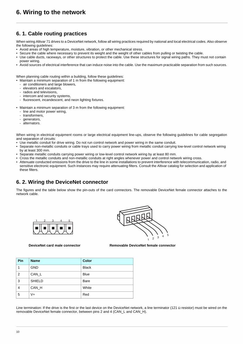
6. 2. Wiring the DeviceNet connectorThe figures and the table below show the pin-outs of the card connectors. The removable DeviceNet female connector attaches to thenetwork cable.
Line termination: If the drive is the first or the last device on the DeviceNet network, a line terminator (121 Ω resistor) must be wired on theremovable DeviceNet female connector, between pins 2 and 4 (CAN_L and CAN_H).
DeviceNet card male connector Removable DeviceNet female connector
Pin Name Color
1 GND Black
2 CAN_L Blue
3 SHIELD Bare
4 CAN_H White
5 V+ Red
1 2 3 4 5
1 2 3 4 5
10

6. Wiring to the network
The ODVA standards (Release 2.0) specify 7 types of cables for use in DeviceNet networks:• Thick cable• Thin cable• Flat cable• Cable I• Cable II• Cable IV• Cable V
The table below lists main specifications of cables. For more information, refer to the ODVA specifications.
The maximum permissible length of the network cable depends an the data rate and the type of cable.
For maximum length of the drops refer to table, whatever type of cable:
Type of cable Data conductor pair size Power conductor pair size Data impedance
Thick cable 18 AWG 15 AWG 120 Ω +/- 10 % (at 1 MHz)
Thin cable 24 AWG 22 AWG 120 Ω +/- 10 % (at 1 MHz)
Flat cable 16 AWG 16 AWG 120 Ω +/- 10 % (at 500 kHz)
Cable I 24 AWG 22 AWG 120 Ω +/- 10 % (at 1 MHz)
Cable II 18 AWG 15 AWG 120 Ω +/- 10 % (at 1 MHz)
Cable IV 18 AWG 16 AWG 120 Ω +/- 10 % (at 500 kHz)
Cable V 18 AWG 16 AWG 120 Ω +/- 10 % (at 500 kHz)
Type of cable Data rate
125 kbit/s 250 kbit/s 500 kbit/s
Thick cable 500 m (1640 ft) 250 m (820 ft) 100 m (328 ft)
Thin cable 100 m (328 ft) 100 m (328 ft) 100 m (328 ft)
Flat cable 420 m (1378 ft) 200 m (656 ft) 75 m (246 ft)
Cable I 100 m (328 ft) 100 m (328 ft) 100 m (328 ft)
Cable II 500 m (1640 ft) 250 m (820 ft) 100 m (328 ft)
Cable IV - - -
Cable V 420 m (1378 ft) 200 m (656 ft) 75 m (246 ft)
Data rate Cumulative drop Maximum drop
125 kbit/s 156 m (516 ft) 6 m (20 ft)
250 kbit/s 78 m (256 ft) 6 m (20 ft)
500 kbit/s 39 m (128 ft) 6 m (20 ft)
11

7. Configuring by the drive HMI
7. 1. Configuring the controlb PrincipleBy the configuration of the control, it is possible to decide from what channel the drive receives its commands and setpoint, eitherpermanently or depending on a switching command.
Numerous configurations are possible. For more information, refer to the Programming manual and Communication parameters manual.The following configurations are some of the possibilities available.
M Control with communication scanner
If the default assemblies (100, 101) are selected, all possibilities of Altivar 71 drive are available.
It is possible to use all profiles and modes of the drive:- I/O profile,- Drivecom profiles with separate or non separate mode.
By the configuration of the communication scanner, it is possible to assign any relevant parameter of the drive to the 4 input and 4 outputvariables of the assemblies.See the input / output interface with the PLC can be fully customised depending on the application.
The use of the communication scanner is als the best way to interface with a "Controller Inside" card.
M Control according to ODVA AC drive profile
The ODVA AC drive profile is activated when one of the following assemblies is selected:• 20: Basic speed control output• 21: Extended speed control output• 22: Speed and torque control output• 23: Extended speed and torque control output• 70: Basic speed control input• 71: Extended speed control input• 72: Speed and torque control input• 73: Extended speed and torque control input
The advantage of using the ODVA drive profile standard is the interchangeability with other brands.
The drive must be configured in the Drivecom profile with separate mode.The DeviceNet card translates the commands, behaviour and monitoring information from of ODVA profile (on the network) to the Drivecomprofile (in the drive).
M Control according to Allen-Bradley® drive profile
The Allen-Bradley® Drive profile is activated when one of the following assemblies is selected:• 103: Allen-Bradley® drive output• 104: Allen-Bradley® drive input• 105: Allen-Bradley® drive input with parameters
If you need to replace Allen-Bradley® drives, in an existing application, this profile is a good way to minimise the modifications.
The drive must be configured in the Drivecom profile with separate mode.The DeviceNet card translates the commands, behaviour and monitoring information from of Allen-Bradley® drive profile (on the network)to the Drivecom profile (in the drive).
12

7. Configuring by the drive HMI
b Available configurationsM If you use the communication scanner:
• 100: Communication scanner output• 101: Communication scanner input there is no limitation in the configuration of the control.
The examples below are only possible if you use the communication scanner.
M If you use the ODVA AC drive profile or Allen-Bradley® Drive profile, that is, the assemblies:
• 20: Basic speed control output• 21: Extended speed control output• 22: Speed and torque control output• 23: Extended speed and torque control output• 70: Basic speed control input• 71: Extended speed control input• 72: Speed and torque control input• 73: Extended speed and torque control input• 103: Allen-Bradley® drive output• 104: Allen-Bradley® drive input• 105: Allen-Bradley® drive input with parameters only some configurations are permitted, they are listed in the table below.
Configuration via the graphic display terminal or the integrated display terminal:
Case 1: Setpoint 1B is connected to the functions (Summing, PID, etc) which remain active even after switching.
Case 2: Setpoint 2 is directly connected to the drive reference limit. If switching is performed, the functions that affect the reference(summing, PID, etc.) are inhibited.
Note: It is not possible to configure the display terminal as a channel.To switch to the display terminal, use the function force local and assign the parameter [Forced local Ref.] to [HMI] (LCC).
Parameter Permitted value CommentProfile Drivecom profile separate The run commands are in Drivecom profile,
the command and the reference can come from different channels.Setpoint 1 configuration Network card Setpoint 1 comes from DeviceNet.Setpoint 1B configuration Terminals Setpoint 2 comes from terminals (AI1 or AI2).Setpoint 2 configuration Terminals Setpoint 2 comes from terminals (AI1 or AI2).Command 1 configuration Network card Command 1 comes from DeviceNet.Command 2 configuration Terminals Command 2 comes from terminals.Setpoint switching Network card bit 12 Bit 12 of the control word switches the setpoint (1 <-> 1B or 1 <-> 2).Command switching Network card bit 13 Bit 13 of the control word switches the command.
Menu Parameter Permitted value[1.6 - COMMAND] (CtL-) [Profile] (CHCF) [Separate] (SEP)
[Ref.1 channel] (Fr1) [Com. card] (nEt)[Ref.1B channel] (Fr1b) [Ref. AI1] (AI1) or [Ref. AI2] (AI2)[Cmd channel 1] (Cd1) [Com. card] (nEt)[Cmd channel 2] (Cd2) [Terminals] (tEr)[Cmd switching] (CCS) [C312] (C312)
[1.7 APPLICATION FUNCT.] (FUn-)[REFERENCE SWITCH.]
[Ref 1B switching] (rCb) [C313] (C313)
Menu Parameter Permitted value[1.6 - COMMAND] (CtL-)[1.7 APPLICATION FUNCT.] (FUn-)[REFERENCE SWITCH.]
[Profile] (CHCF) [Separate] (SEP)[Ref.1 channel] (Fr1) [Com. card] (nEt)[Ref.2 channel] (Fr2) [Ref. AI1] (AI1) or [Ref. AI2] (AI2)[Cmd channel 1] (Cd1) [Com. card] (nEt)[Cmd channel 2] (Cd2) [Terminals] (tEr)[Cmd switching] (CCS) [C312] (C312)[Ref. 2 switching] (rFC) [C313] (C313)
13
7. Configuring by the drive HMI
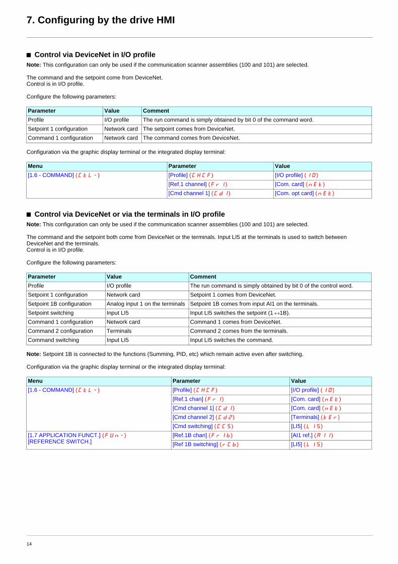
b Control via DeviceNet in I/O profileNote: This configuration can only be used if the communication scanner assemblies (100 and 101) are selected.
The command and the setpoint come from DeviceNet.Control is in I/O profile.
Configure the following parameters:
Configuration via the graphic display terminal or the integrated display terminal:
b Control via DeviceNet or via the terminals in I/O profileNote: This configuration can only be used if the communication scanner assemblies (100 and 101) are selected.
The command and the setpoint both come from DeviceNet or the terminals. Input LI5 at the terminals is used to switch between DeviceNet and the terminals.Control is in I/O profile.
Configure the following parameters:
Note: Setpoint 1B is connected to the functions (Summing, PID, etc) which remain active even after switching.
Configuration via the graphic display terminal or the integrated display terminal:
Parameter Value CommentProfile I/O profile The run command is simply obtained by bit 0 of the command word.Setpoint 1 configuration Network card The setpoint comes from DeviceNet.Command 1 configuration Network card The command comes from DeviceNet.
Menu Parameter Value[1.6 - COMMAND] (CtL-) [Profile] (CHCF) [I/O profile] (IO)
[Ref.1 channel] (Fr1) [Com. card] (nEt)[Cmd channel 1] (Cd1) [Com. opt card] (nEt)
Parameter Value CommentProfile I/O profile The run command is simply obtained by bit 0 of the control word.Setpoint 1 configuration Network card Setpoint 1 comes from DeviceNet.Setpoint 1B configuration Analog input 1 on the terminals Setpoint 1B comes from input AI1 on the terminals.Setpoint switching Input LI5 Input LI5 switches the setpoint (1 ↔1B).Command 1 configuration Network card Command 1 comes from DeviceNet.Command 2 configuration Terminals Command 2 comes from the terminals.Command switching Input LI5 Input LI5 switches the command.
Menu Parameter Value[1.6 - COMMAND] (CtL-) [Profile] (CHCF) [I/O profile] (IO)
[Ref.1 chan] (Fr1) [Com. card] (nEt)[Cmd channel 1] (Cd1) [Com. card] (nEt)[Cmd channel 2] (Cd2) [Terminals] (tEr)[Cmd switching] (CCS) [LI5] (LI5)
[1.7 APPLICATION FUNCT.] (FUn-)[REFERENCE SWITCH.]
[Ref.1B chan] (Fr1b) [AI1 ref.] (AI1)[Ref 1B switching] (rCb) [LI5] (LI5)
14

7. Configuring by the drive HMI
b Control via DeviceNet in Drivecom profileNote: This configuration can only be used if the communication scanner assemblies (100 and 101) are selected.
The command and the setpoint come from DeviceNet.
Configure the following parameters:
Configuration via the graphic display terminal or the integrated display terminal:
b Control via DeviceNet or the terminals in Drivecom profileNote: This configuration can only be used if the communication scanner assemblies (100 and 101) are selected.
The command and the setpoint both come from DeviceNet or the terminals. Input LI5 at the terminals is used to switch between DeviceNet and the terminals.
Configure the following parameters:
Note: Setpoint 2 is directly connected to the drive reference limit. If switching is performed, the functions that affect the reference (summing,PID, etc) are inhibited.
Configuration via the graphic display terminal or the integrated display terminal:
Parameter Value CommentProfile Separate Drivecom profile The run commands are in Drivecom profile, the command and the setpoint can
come from different channels.Setpoint 1 configuration Network card The setpoint comes from DeviceNet.Command 1 configuration Network card Command 1 comes from DeviceNet.
Menu Parameter Value[1.6 - COMMAND] (CtL-) [Profile] (CHCF) [Separate] (SEP)
[Ref.1 chan] (Fr1) [Com. card] (nEt)[Cmd channel 1] (Cd1) [Com. card] (nEt)
Parameter Value CommentProfile Separate Drivecom profile The run commands are in Drivecom profile, the command and the
setpoint can come from different channels.Setpoint 1 configuration Network card Setpoint 1 comes from DeviceNet.Setpoint 2 configuration Analog input 1 on the terminals Setpoint 2 comes from input AI1 on the terminals.Setpoint switching Input LI5 Input LI5 switches the setpoint (1 ↔ 2) and the command.Command 1 configuration Network card Command 1 comes from DeviceNet.Command 2 configuration Terminals Command 2 comes from the terminals.Command switching Input LI5 Input LI5 switches the command.
Menu Parameter Value[1.6 - COMMAND] (CtL-) [Profile] (CHCF) [Separate] (SEP)
[Ref.1 chan] (Fr1) [Com. card] (nEt)[Ref.2 chan] (Fr2) [AI1 ref.] (AI1)[Ref. 2 switching] (rFC) [LI5] (LI5)[Cmd channel 1] (Cd1) [Com. card] (nEt)[Cmd channel 2] (Cd2) [Terminals] (tEr)[Cmd switching] (CCS) [LI5] (LI5)
15

7. Configuring by the drive HMI
b Control in Drivecom profile via DeviceNet and setpoint switching at the terminalsNote: This configuration can only be used if the communication scanner assemblies (100 and 101) are selected.
The command comes from DeviceNet.The setpoint comes either from DeviceNet or from the terminals. Input LI5 at the terminals is used to switch the setpoint between DeviceNetand the terminals.Control is in Drivecom profile.
Configure the following parameters:
Note: Setpoint 1B is connected to the functions (summing, PID, etc) that remain active, even after switching.
Configuration via the graphic display terminal or the integrated display terminal:
Parameter Value CommentProfile Separate Drivecom profile The run commands are in Drivecom profile, the command and the
setpoint can come from different channels.Setpoint 1 configuration Network card Setpoint 1 comes from DeviceNet.Setpoint 1B configuration Analog input 1 on the terminals Setpoint 1B comes from input AI1 on the terminals.Setpoint switching Input LI5 Input LI5 switches the setpoint (1 ↔1B).Command 1 configuration Network card Command 1 comes from DeviceNet.Command switching Channel 1 Channel 1 is the command channel.
Menu Parameter Value[1.6 - COMMAND] (CtL-) [Profile] (CHCF) [Separate] (SEP)
[Ref.1 chan] (Fr1) [Com. card] (nEt)[Cmd channel 1] (Cd1) [Com. card] (nEt)[Cmd switching] (CCS) [ch1 active] (Cd1)
[1.7 APPLICATION FUNCT.] (FUn-)[REFERENCE SWITCH.]
[Ref.1B chan] (Fr1b) [AI1 ref.] (AI1)[Ref 1B switching] (rCb) [LI5] (LI5)
16

7. Configuring by the drive HMI
7. 2. Configuring the communication scannerYou need to read this chapter only if you use the assemblies 100 or 101 that use the drive communication scanner.
The variables exchanged by the output assembly 100 and input assembly 101 are selected by configuring the communication scanner.
The 4 output variables are assigned by means of the 4 parameters [Scan. Outp address] (nCAp). They are configured using the graphicdisplay terminal via the [1.9 - COMMUNICATION] (COM-) menu, [COM. SCANNER OUTPUT] (OCS-) submenu.
The 4 input variables of the assembly 101 are assigned by means of the 4 parameters [Scan. Inp address] (nMAp). They are configuredusing the graphic display terminal via the [1.9 - COMMUNICATION] (COM-) menu, [COM. SCANNER INPUT] (ICS-) submenu.
Enter the logic address of the parameter (see the Communication parameters manual).If a parameter [Scan. Outp address] (nCAp) or [Scan. Inp address] (nMAp) is equal to zero, the corresponding period variable is notused by the drive.
These 8 assignment parameters are described in the tables below:
[Scan. Out5 address] (nCA5) to [Scan. Out8 address] (nCA8) are not useful for the DeviceNet card.
[Scan. In5 address] (nCA5) to [Scan. In8 address] (nCA8) are not useful for the DeviceNet card.
Example of configuration via the graphic display terminal:
Note:All modifications to parameters [Scan. Outp address] (nCAp) or [Scan. Inp address] (nMAp) must be made with the motor stopped. Themaster PLC program should be updated to take account of this modification.
Parameter name Output assembly 100 Default assignment[Scan. Out1 address] (nCA1) Bytes 0 and 1 Control word (CMd)[Scan. Out2 address] (nCA2) Bytes 2 and 3 Speed reference (LFrd)[Scan. Out3 address] (nCA3) Bytes 4 and 5 Not used[Scan. Out4 address] (nCA4) Bytes 6 and 7 Not used
Parameter name Input assembly 101 Default assignment[Scan. In1 address] (nMA1) Bytes 0 and 1 Status word (EtA)[Scan. In2 address] (nMA2) Bytes 2 and 3 Output speed (rFrd)[Scan. In3 address] (nMA3) Bytes 4 and 5 Not used[Scan. In4 address] (nMA4) Bytes 6 and 7 Not used
RDY NET +0.00Hz 0A RDY NET +0.00Hz 0A
COM. SCANNER INPUT COM. SCANNER OUTPUT
Scan. In1 address : 3201 Scan. Out1 address : 8501
Scan. In2 address : 8604 Scan. Out2 address : 8602
Scan. In3 address : 0 Scan. Out3 address : 0
Scan. In4 address : 0 Scan. Out4 address : 0
Scan. In5 address : 0 Scan. Out5 address : 0
Code Quick Code Quick
Scan. In6 address : 0 Scan. Out6 address : 0
Scan. In7 address : 0 Scan. Out7 address : 0
Scan. In8 address : 0 Scan. Out8 address : 0
17

7. Configuring by the drive HMI
Example of configuration of communication scanner assemblies 100 and 101The following output and input variables are to be configured:
Configuration settings to be made:
Output assembly 100 Parameter assigned Input assembly 101 Parameter assignedBytes 0 and 1 Control word (CMd) Bytes 0 and 1 Status word (EtA)Bytes 2 and 3 Speed reference (LFrd) Bytes 2 and 3 Output speed (rFrd)Bytes 4 and 5 Acceleration (ACC) Bytes 4 and 5 Speed reference before ramp (FrHd)Bytes 6 and 7 Deceleration (dEC) Bytes 6 and 7 Logic input map (IL1r)
Communication scanner inputs
Parameter logic address Communication scanner outputs
Parameter logic address
[Scan. Out1 address] (nCA1) 8501 [Scan. IN1 address] (nMA1) 3201
[Scan. Out2 address] (nCA2) 8602 [Scan. IN2 address] (nMA2) 8604
[Scan. Out3 address] (nCA3) 9001 [Scan. IN3 address] (nMA3) 8605
[Scan. Out4 address] (nCA4) 9002 [Scan. IN4 address] (nMA4) 5202
18

7. Configuring by the drive HMI
7. 3. Configuring the fault managementThe DeviceNet card may detect 2 types of faults:
- Communication fault,- Configuration fault.
The communication fault occurs when there is a time out on control traffic: COS, cyclic, polling or explicit messaging. In factory setting, thecommunication fault triggers a [Com. network] (CnF) fault.
The configuration fault occurs when: - ODVA AC drive profile or Allen-Bradley® Drive profile are used (assemblies 20, 21, 22, 23, 70, 71, 72, 73, 103, 104, 105), - the configuration of the drive control parameters is not correct (refer to 7. 1. Configuring the control),- a DeviceNet connection is active between the drive and the PLC.
In factory setting, the communication fault triggers a [External fault com.] (EPF2) fault.
The response of the drive in the event of a DeviceNet communication fault can also be configured.
The values of the [Network fault mgt] (CLL) or [External fault ass.] (EPL) parameters, which trigger a drive fault [Com. network] (CnF),are:
The values of the [Network fault mgt] (CLL) or [External fault ass.] (EPL) parameters, which do not trigger a drive fault, are:
The fallback speed can be configured in the [1.8 – FAULT MANAGEMENT] (FLt-) menu using the [Fallback speed] (LFF) parameter.
Configuration can be performed using the graphic display terminal or integrated display terminal in the [1.8 - FAULT MANAGEMENT] (FLt-) menu:
- For the communication fault, in the [COM. FAULT MANAGEMENT] (CLL-) submenu, via the [Network fault mgt] (CLL) parameter.
- For the configuration fault, in the [EXTERNAL FAULT] (EtF-) submenu, via the [External fault ass.] (EPL) parameter.
RDY NET +0.00Hz 0A
COM. FAULT MANAGEMENT
Network fault mgt : Freewheel
CANopen fault mgt : Freewheel
Modbus fault mgt : Freewheel
Code Quick
Value Meaning
[Freewheel] (YES) Freewheel stop (factory setting)
[Ramp stop] (rMP) Stop on ramp
[Fast stop] (FSt) Fast stop
[DC injection] ( )dCI DC injection stop
Value Meaning
[Ignore] (nO) Fault ignored
[Per STT] (Stt) Stop according to configuration of [Type of stop] (Stt).
[fallback spd] (LFF) Switch to fallback speed, maintained as long as the fault is present and the run command is not disabled.
[Spd maint.] (rLS) The drive maintains the speed at the time the fault occurred, as long as the fault persists and the run command has not been removed.
19

7. Configuring by the drive HMI
7. 4. Configuring monitored parametersIt is possible to select up to 4 parameters to display their values in the [1.2 - MONITORING] menu ([COMMUNICATION MAP] submenu)on the graphic display terminal.
The selection is made via the [6 – MONITOR CONFIG.] menu ([6.3 - CONFIG. COMM. MAP] submenu).
One of the three display formats below can be assigned to each monitored word:
Each parameter [Address 1 select] ... [Address 4 select] can be used to choose the logic address of the parameter. Select an address of zero to disable the function.
In the example given here, the monitored words are:
• Parameter 1 = Motor current (LCr): Logic address 3204;signed decimal format
• Parameter 2 = Motor torque (Otr): logic address 3205; signed decimal format
• Parameter 3 = Last fault occurred (LFt): logic address 7121; hexadecimal format
• Disabled parameter: Address W0; default format: hexadecimal format
RDY NET +0.00Hz 0A
6.3 CONFIG. COMM. MAP.
Address 1 select : 3204
FORMAT 1 : Signed
Address 2 select : 3205
FORMAT 2 : Signed
Address 3 select : 7121
Code Quick
FORMAT 3 : Hex
Address 4 select : 0
FORMAT 4 : Hex
Format Range Terminal displayHexadecimal 0000 ... FFFF [Hex]Signed decimal -32 767 ... 32 767 [Signed]Unsigned decimal 0 ... 65 535 [Unsigned]
20

8. Configuring by a network tool
8. 1. Network toolRSNetWorx for DeviceNet is a Rockwell® software application that can be used to set up DeviceNet networks and configure connecteddevices.
RSNetWorx for DeviceNet (version 2.22.18) is used for examples in this manual. Different versions of software may differ in appearanceand procedures.
Proper EDS file (A71vp_E.eds) and icone (Altivar_71.ico) for Altivar drives are distributed on the CD-ROM delivered with each drive. Theyare also available on the Internet : www.telemecanique.com
8. 2. Going online with RSNetWorxYou can view the devices on a DeviceNet network by going online. A device may appear as an unrecognised device if RSNetWorx doesnot have an EDS file for it.
1 After setting up a driver in RSLinx, start RSNetWorx for DeviceNet.
2 Select Network > Online. If the Browse for Network dialog box appears, RSLinx has multiple drivers configured.Select your DeviceNet network, and click OK. A prompt appears.
3 Click OK to go online. The devices on the network appear in the Configuration View. You can select Graph, Spreadsheet, or Master/Slave views. The figure below shows an example network in a Graph view.
8. 3. Creating an EDS fileIf the adapter and drive appear as an unrecognized device, create an EDS file for it.
1 Right-click the "Unrecognized Device" icon, and select Register Device in the menu. The EDS Wizard appears.
2 Click Next to display the next step.
3 Select Upload EDS, and then click Next.
4 Type a description (if desired), and then click Next.
5 Under Polled, select Enabled, type 4 in the Input Size and Output Size boxes, and then click Next. RSNetWorx will upload the EDS file from the deviceNet card.
6 Click Next to display the icon options for the node. We recommend that you use the icon for your product. You can change icons by clicking Change icon.Proper icon (Altivar_71.ico) is distributed on the CD-ROM delivered with each drive. They are also available on the Internet : www.telemecanique.com
7 Click Next to view a summary, and then click Next again to accept it.
8 Click Finish to finish the EDS creation. A new icon represents the Altivar drive in the Configuration View.
21
8. Configuring by a network tool
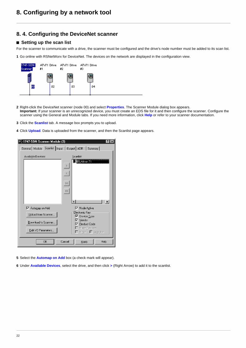
8. 4. Configuring the DeviceNet scannerb Setting up the scan listFor the scanner to communicate with a drive, the scanner must be configured and the drive's node number must be added to its scan list.
1 Go online with RSNetWorx for DeviceNet. The devices on the network are displayed in the configuration view.
2 Right-click the DeviceNet scanner (node 00) and select Properties. The Scanner Module dialog box appears.Important: If your scanner is an unrecognized device, you must create an EDS file for it and then configure the scanner. Configure the scanner using the General and Module tabs. If you need more information, click Help or refer to your scanner documentation.
3 Click the Scanlist tab. A message box prompts you to upload.
4 Click Upload. Data is uploaded from the scanner, and then the Scanlist page appears.
5 Select the Automap on Add box (a check mark will appear).
6 Under Available Devices, select the drive, and then click > (Right Arrow) to add it to the scanlist.
22

8. Configuring by a network tool
7 Under Scanlist, select the drive, and then click Edit I/O Parameters.The Edit I/O Parameters dialog box appears.
8 Select the type(s) of data exchange (Polled, Change of State, and /or Cyclic). In our example, we selected Polled.
The type supported by the DeviceNet card for Altivar are:
9 Type the number of bytes that are required for your I/O in the Rx Size and Tx Size boxes. The size will depend on the assembly you have selected for your application:
10 Set the scan rate. (Click Help for more information.)
11 Click OK.If you changed any settings, a Scanner Applet asks if it is OK to unmap the I/O. Click Yes to continue. The Edit I/O Parameters dialog box closes and then the Scanner Module dialog box reappears.You will map the I/O in the next section in this chapter.
Polled COS Cyclic StrobeInput (Rx, produced) p p p NoOutput (Tx, consummed) p No No No
Assembly attribute Assembly name Rx size70 ODVA Basic speed control input 4 bytes71 ODVA Extended speed control input 4 bytes72 ODVA Speed and torque control input 6 bytes73 ODVA Extended speed and torque control input 6 bytes101 Communication scanner input 8 bytes104 Allen-Bradley® drive input 4 bytes105 Allen-Bradley® drive input with parameters 8 bytes
Assembly attribute Assembly name Tx size20 ODVA Basic speed control output 4 bytes21 ODVA Extended speed control output 4 bytes22 ODVA Speed and torque control output 6 bytes23 ODVA Extended speed and torque control output 6 bytes100 Communication scanner output 8 bytes103 Allen-Bradley® drive output 4 bytes
Data Exchange Rate to setPolled Polled RateChange of State Heartbeat RateCyclic Send Rate
23

8. Configuring by a network tool
b Mapping the drive data in the scannerData from I/O messages must be mapped in the scanner. This mapping determines where a PLC program can find data that is passed overthe network. You must map both the Input I/O and the Output I/O.
M Mapping the inputs
1 In the Scanner Module dialog box, click the Input tab. (If necessary, right-click the scanner in the configuration view to display this dialog box.)
The figure below is an example for assembly 73 (ODVA Extended speed and torque control input).
If you selected the Automap on Add box in the Scanlist page, RSNetWorx has already mapped the I/O. If it is not mapped, click Automap to map it. If you need to change the mapping, click Advanced and change the settings. Click Help for assistance.
2 In the Memory box, select a location in scanner memory.
In our example, we are using a 1747-SDN and selected Discrete.
3 In the Start Word box, select the word in memory at which the data should start.In our example, we selected 3. The drive parameters will be mapped:
Scanner Memory Locations1747-SDN Discrete or M-File1756-DNB Assembly Data1771-SDN Block Xfer 62 - 57
Input Parameter of the driveI:1.3 Status wordI:1.4 Actual speedI:1.5 Actual torque
24

8. Configuring by a network tool
M Mapping the outputs
1 In the Scanner Module dialog box, click the Output tab. To display this dialog box, right-click the scanner in the configuration view.
The figure below is an example for assembly 23 (ODVA Extended speed and torque control output).
If you selected the Automap on Add box in the Scanlist page, RSNetWorx has already mapped the I/O. If it is not mapped, click Automap to map it. If you need to change the mapping, click Advanced and change the settings. Click Help for assistance.
2 In the Memory box, select a location in scanner memory.
In our example, we are using a 1747-SDN and selected Discrete.
3 In the Start Word box, select the word in memory at which the data should start.In our example, we selected 3. The drive parameters will be mapped:
Scanner Memory Locations1747-SDN Discrete or M-File1756-DNB Assembly Data1771-SDN Block Xfer 62 - 57
Input Parameter of the driveO:1.3 Control wordO:1.4 Speed setpointO:1.5 Torque setpoint
25

8. Configuring by a network tool
b Saving the ConfigurationAfter configuring a scanner, you must download the configuration to the scanner. You should also save it to a file on your computer.
1 In the Scanner Module dialog box, click Apply to save the configuration to the scanner. A Scanner Configuration Applet appears and asks if it is OK to download the changes.
2 Click Yes to download the changes. The changes are downloaded and then the Scanner Module dialog box reappears.
3 Click OK to close the Scanner Module dialog box.
4 Select File > Save. If this is the first time that you saved the project, the Save As dialog box appears. Navigate to a folder, type a file name, and click Save to save the configuration to a file.
b Auto Device ReplacementDo not activate ADR (Auto Device Replacement).
Parameters download of the Altivar drive needs a specific process:1 Upload the drive parameters:
- Read drive parameters using explicit messages.- Store the parameters in a data table of the PLC.
2 Dowload the drive parameters:- Disable consistency check (Set bit 15 of the parameter Extended control word (CMI)).- Write parameters from the data table of the PLC to the drive using explicit messages.- Enable consistency check (Reset bit 15 of the parameter parameter Extended control word (CMI)).
3 Read and compare the parameters between the drive and the save table.
Extended control word (CMI)
This sequence must be programmed in the PLC.
It is necessary to disable the consistency check before writing parameters.If the consistency check is not disabled, the drive verifies, at each Set access, if the parameter matches with the others. If it does not match,the drive modifies or rejects the parameter.
Base Class Instance AttributeHexadecimal 16# 8B 16#01 16#69Decimal 139 1 105
26

8. Configuring by a network tool
8. 5. Editing parameters of the driveb Using the Device Parameters editorParameters in the drive and in the DeviceNet card can be edited with Device Parameters editor of RSNetWorx, if they are described in theeds file.
1 After creating an EDS file, right-click on the icon for the Altivar drive and select Properties. The Altivar drive dialog box appears.
2 Click the Device Parameters tab. If an EDS Editor message appears, click Upload to load the parameter values in the drive to the computer.Parameters are displayed in numerical order under Parameter. You can either scroll through the list or select a specific group of parameters in the Groups box. The available groups and the numbers of parameters will vary based on the type of drive.
3 In the Current Value column, double-click a value to edit it.
4 Click Apply to save changes to the drive.
27

8. Configuring by a network tool
b Limitations of the Device Parameters editorIf you use the feature Download To Device / All, you may encounter unexpected events:• If you first Upload From Device / All and then Download To Device / All, the actual configuration of the drive may be different from the
one that you initially saved.• A fault [External fault com.] (EPF2) may occur.
We do not recommended to used the feature Download To Device / All.You assume full responsibility for all consequences related to the use of this feature.
M Additional information for Download To Device / All
The Download To Device / All function uses sequential explicit messaging to the parameters described in the eds file.Each time it receives Set access to a parameter, the drive checks the consistency of this parameter with the others (values already existingin the drive).If there is an inconsistency, the drive rejects the parameter or modifies it according to internal rules (parameter management).
Example:A rule of the parameter management is: [Low speed] (LSP) must be lower or equal to [High speed] (HSP).
Initially [Low speed] (LSP) = 20Hz and [High speed] (HSP) = 30Hz.The Download To Device / All function writes sequentially : [Low speed] (LSP) = 35Hz and then [High speed] (HSP) = 50Hz.
The result in the drive will be [Low speed] (LSP) = 30Hz and [High speed] (HSP) = 50Hz and so the configuration served will be differentfrom the one saved in an Upload From Device / All.
M Additional information for fault [External fault com.] (EPF2)
When the drive uses assemblies 20, 21, 22, 23, 70, 71, 72, 73, 103, 104 or 105, there are conditions on the values of the parameters (referto 7.1 Configuring the control):• [Profile] (CHCF),• [Ref.1 channel] (Fr1),• [Ref.1B channel] (Fr1b),• [Ref.2 channel] (Fr2),• [Cmd channel 1] (Cd1),• [Cmd channel 2] (Cd2),• [Ref 1B switching] (rCb),• [Ref. 2 switching] (rFC),• [Cmd switching] (CCS).
If during the Download To Device / All operation, the conditions are not fulfilled the fault [External fault com.] (EPF2) occurs.It may occur also if the problem appears only once during operation, even though at the end the configuration is valid.
28

8. Configuring by a network tool
b Configuring the assembliesThe default assemblies are :
If you use them, you do not need reading this section.
If you use another assembly, you must configure it in the drive.
M Selecting the input assembly
1 In the Groups box, select DeviceNet Interface.
2 For the parameter PollProdPath, in the Current Value column, select the input assembly that fits to your application.
3 For the parameter PollConsPath, in the Current Value column, select the input assembly that fits to your application.
Assembly attribute Assembly name100 Communication scanner output101 Communication scanner input
Assembly attribute Assembly name70 ODVA Basic speed control input71 ODVA Extended speed control input72 ODVA Speed and torque control input73 ODVA Extended speed and torque control input101 Communication scanner input104 Allen-Bradley® drive input105 Allen-Bradley® drive input with parameters
29

8. Configuring by a network tool
M Selecting the output assembly
1 In the Groups box, select DeviceNet Interface.
2 For the parameter CCProdPath, in the Current Value column, select the assembly that fits to your application.
M Selecting additional parameters of assembly 105
If you use assembly 105, apply the procedure below, otherwise skip this section and read below: Saving changes in the drive.
1 Select the additional parameters that you need for your application.Example : [Motor current] (LCr) and [Motor torque] (Otr).
2 Refer to the Communication parameters manual. Write down the class Id and the attribute id of the parameters. Convert the hexadecimal values to decimal values.Example :
3 In the Groups box, select DeviceNet Interface.
4 For the parameter FirstParamClass, in the Current Value column, type the class value in decimal.Example : 42.
5 For the parameter FirstParamAttr, in the Current Value column, type the attribute value in decimal.Example : 9.
6 If you need a second additional parameter, for the parameter SecondParamClass, in the Current Value column, type the class value in decimal.Example : 113.If you do not need skip to step Saving changes in the drive.
7 For the parameter SecondParamAttr, in the Current Value column, type the attribute value in decimal.Example : 6.
M Saving changes in the drive
1 Click Apply to save changes to the device.
2 Cycle power off / on the drive.
Assembly attribute Assembly name Tx size20 ODVA Basic speed control output 4 bytes21 ODVA Extended speed control output 4 bytes22 ODVA Speed and torque control output 6 bytes23 ODVA Extended speed and torque control output 6 bytes100 Communication scanner output 8 bytes103 Allen-Bradley® drive output 4 bytes
Parameter name Path Class Id Attribute idHexadécimal Décimal Hexadécimal Décimal
[Motor current] (LCr)
2A/01/09 16#2A 42 16#09 9
[Motor torque] (Otr)
71/01/06 16#71 113 16#06 6
30

8. Configuring by a network tool
b Configuring node address and data rateIf the data rate switches (7 and 8) are set to 1, it is possible to configure node address and data rate by the Device Parameters editor ofRSNetWorx.
M Configuring the node address
1 Connect the drive on the network. The default value of the node address is 63. So you must no connect simultaneously several drives with software configured node address. You must connect and set the address of drives one by one.
2 Go on line with the drive and launch the Device Parameters editor of RSNetWorx.
3 In the Groups box, select DeviceNet.
4 For the parameter MAC ID, in the Current Value column, type the address value. The new value is immediately applied to the drive and stored in EEPROM (so used at each power-up of the drive).
M Configuring the data rate
1 Connect the drive on the network. The default value of the data rate is 125kbit/s. If it does not match the data rate of the DeviceNet network, you must temporarily set the data rate of the network tool 125kbit/s in order to access the drive and modify its data rate.
2 Go on line with the drive and launch the Device Parameters editor of RSNetWorx.
3 In the Groups box, select DeviceNet.
4 For the parameter Baud rate, in the Current Value column, select the data rate value. The new value will be applied to the drive at next power-up. It is stored in EEPROM (so used at each power-up of the drive).
31

8. Configuring by a network tool
8. 6. Editing objects of the driveb Using the Class Instance EditorDeviceNet objects of the drive and the DeviceNet card can be edited with the Class Instance Editor of RSNetWorx.
This editor provides direct access to the device using native DeviceNet object addressing.Using this editor requires a detailed understanding of the capabilities and limitations of the device being configured, as well as the possibleimpacts that these changes may have on the operation of your system. You assume full responsibility for all consequences related to theuse of this editor.
1 Go online with RSNetWorx for DeviceNet. The devices on the network are displayed in the configuration view.
32

8. Configuring by a network tool
2 Right-click on the icon for the Altivar drive and select Class Instance Editor. The Altivar drive dialog box appears.
3 In the Object Address field, type the path of the parameter in the boxes Class, Instance, Attribute.
4 In the Service Code field, select the action in the Description box.
5 In the boxes Transmit data size, Data sent to the device, Values in decimal type the description of the data that you want to send to the drive.
6 Click Execute to exchange the data with the drive. Click Help for assistance.
33

8. Configuring by a network tool
b Configuring NetRef parameterConfigure NetRef by the Class Instance Editor for testing.
It is possible to provide the speed setpoint with output assembly 20, if the parameter NetRef is set to.
The default value is 0, output assembly 20 controls the drive but the speed target is given by the terminals (AI1).
The default setting applies each time the connection is closed (Power on of the drive, DeviceNet disconnected from the card).
If assembly 20 must be used, the PLC program must set this parameter by explicit messaging.It may be easier to use another assembly (21).
b Configuring node address and data rateIf the data rate switches (7 and 8) are set to 1, configure node address and data rate by the Class Instance Editor.
Node address
Data rate
Base Class Instance AttributeHexadecimal 16# 2A 16#01 16#04Decimal 42 1 4
Base Class Instance AttributeHexadecimal 16# 03 16#01 16#01Decimal 3 1 1
Base Class Instance AttributeHexadecimal 16# 03 16#01 16#02Decimal 3 1 2
34

9. Creating a PLC program
9. 1. Using I/O messagingI/O messaging is used to transfer real time data between the PLC and the drive :• Commands,• Setpoints,• Settings,• States,• Measurements,• ...
Depending on your application needs and other constraints, select the right assemblies:• communication scanner assemblies and configure the parameters of the assembly (refer to 8. 4. Configuring the DeviceNet scanner),• or ODVA AC drive profile,• or Allen-Bradley® Drive profile (you can select 2 monitoring parameters in assembly 105).
To obtain the best response time in the application choose the adequate exchange method:• Change of State (COS),• Cyclic,• or Polled.
The exchange method is downloaded in the drive by the DeviceNet scanner and must be configured by network tool (refer to 8. 4.Configuring the DeviceNet scanner).
9. 2. Using explicit messagingI/O messaging is used to transfer data that does not require continuous updates between the PLC and the drive :• Configuration,• Settings,• Fault parameters,• Log parameters;• ...
If the PLC program configures the drive using explicit messaging.The new value of the parameters are not stored in EEPROM and they will be lost at next power off.To store the values of parameters (whole configuration) in EEPROM, it is necessary to set to 1 the bit 1 of Extended control word (CMI),refer to the Communication parameters manual.
35

10. Diagnostics by the drive HMI
10. 1. Checking the node address and the data rateOn the graphic or integrated HMI, you can check the node address and the data rate through the menu [1.9 - COMMUNICATION] (COM-)sub-menu [DeviceNet] (dnt-).
These parameters are both "read only" (i.e. their value cannot be changed with the HMI):
Keypad Display Range Remarks
[Address] (AdrC) [0] (0) ... [63] (63) If data rate switches (7 and 8) are both set to 1 (ON), the default node address of the drive is 63, until it is set by network tool.
[Data rate] (bdr) [125 kbd] (125)[250 kbd] (250)[500 kbd] (500)
If data rate switches (7 and 8) are both set to 1 (ON), the default data rate of the drive is 125 kbit/s, until it is set by network tool.
36

10. Diagnostics by the drive HMI
10. 2. Signalling LEDThe DeviceNet card features one combined Module/Network Status LED (MNS) in position 2.1, which is visible through the drive cover:
LED status indication
Note: After power on, the MNS LED quickly glows green then red and finally turns off.
LED state Drive controller state Indication
Off Device is not on line • The device is not powered.• The device has not completed the duplicate node address test yet.
Flasching green Device is operational and on line, but not connectedORDevice is on line but needs commissioning
The device is on line and operating in a normal condition, but network connections are not established.• The device has passed the duplicate node address test and is on line, but has not established connections to other nodes.• The device is not allocated to a master.• Configuration is missing, incomplete, or incorrect.
Speady green Device is operational, online, and connected
The device is operating in a normal condition.It is allocated to a master.
Flasching red Major fault and/or connection time-out
• The device has experienced a major recoverable fault.• One or more I/O connections timed out.
Speady red Critical fault orcritical link failure
• The card has a major unrecoverable fault and may need replacing.• The device has detected an error that has rendered it incapable of communicating on the network (duplicate node address or bus turned off).
Flashing green / red Communication fault The device has detected a Network Access error and is in the Communication Faulted state. The device has subsequently received and accepted an Identify Communication Faulted Request—Long Protocol message.
1.11.21.31.41.5
2.12.22.32.42.5
MNS
37

10. Diagnostics by the drive HMI
10. 3. Monitoring the controlOn the graphic display terminal only, the [1.2 - MONITORING] menu ([COMMUNICATION MAP] submenu) can be used to display control-signal diagnostic information between the drive and the DeviceNet PLC:
Note: The DeviceNet card receives from the network a control word and sends a status word.The drive has its own drive control word and status word.The network information and the drive information can match or not:
- If the output assembly 100 and the input assembly 101 are selectedandif drive control word and drive status word are assigned to the assemblies then the values displayed in the [COMMUNICATION MAP] submenu represent the values on the DeviceNet network.The drive can be in I/O profile or DSP402 / Drivecom profile.
- In the other cases (assemblies 21, 71, 103 ...), the DeviceNet card processes the commands coming from the network (in Allen Bradley ® drive profile or ODVA profile). It calculates a drive control word according to DSP402 / Drivecom profile.This DSP402 / Drivecom control word of drive if displayed and not the network one.
RUN NET +50.00Hz 80A
COMMUNICATION MAP
Command Channel : COM. CARD
Cmd value : 000FHex
Active ref. channel : COM. CARD
Frequency ref. : 500.0Hz
Status word : 8627Hex
Code Quick
W3204 : 53
W3205 : 725
W7132 : 0000Hex
W0 : -----Hex
COM. SCANNER INPUT MAP
COM SCAN OUTPUT MAP
CMD. WORD IMAGE
FREQ. REF. WORD MAP
MODBUS NETWORK DIAG
MODBUS HMI DIAG
CANopen MAP
PROG. CARD SCANNER
Active command channel
Value of control wordused to control the drive
(hexadecimal format)
Active reference channel
Value of frequency reference (unit 0.1 Hz)used to control the drive
Value of status word(hexadecimal format)
Values of the four monitored words selected by the user.The address and display format of these parameters can be
configured in the [6 - MONITORING CONFIG.] menu,[6.3 - COM. MAP CONFIG.] submenu
(see the "Configuration" section on page 20).The value of a monitored word is equal to "-----" if:
- Monitoring is not activated (address equal to W0)
- The parameter is protected- The parameter is not known (e.g., W3200)
Input assembly 101 variables values
Output assembly 100 variables values
Control word from DeviceNet[COM. card cmd.] (CMd3)
Frequency reference from DeviceNet[Com. card ref.] (LFr3)
38

10. Diagnostics by the drive HMI
10. 4. Monitoring the communication scannerYou only need to read this chapter if you use the assemblies 100 or 101. These assemblies use the drive communication scanner.
On the graphic display terminal, in the [1.2 - MONITORING] (SUP-) menu ([COMMUNICATION MAP] (CMM-) submenu):
- The [COM. SCANNER INPUT MAP] (ISA-) submenu is used to display the value of the variables of the input assembly 101: 4 communication scanner input parameters [Com Scan Inp val.] (NMp).
- The [COM SCAN OUTPUT MAP] (OSA-) submenu is used to display the value of the variables of the output assembly 100: 4 communication scanner output parameters [Com Scan Outp val.] (NCp).
[Com Scan. In5 val.] (NM5) to [Com Scan In8 val.] (NM8) and [Com Scan Out5 val.] (NC5) to [Com Scan Out8 val.] (NC8) are not used bythe DeviceNet card.
Configuration of these parameters is described in the "Configuration" section.
Example:
In this example, only the first two parameters have been configured (default assignment).
Input assembly 101 Scanner parameter Output assembly 100 Scanner parameterBytes 0 and 1 [Com Scan In1 val.] (NM1) Bytes 0 and 1 [Com Scan Out1 val.] (NC1)
Bytes 2 and 3 [Com Scan In2 val.] (NM2) Bytes 2 and 3 [Com Scan Out2 val.] (NC2)
Bytes 4 and 5 [Com Scan In3 val.] (NM3) Bytes 4 and 5 [Com Scan Out3 val.] (NC3)
Bytes 6 and 7 [Com Scan In4 val.] (NM4) Bytes 6 and 7 [Com Scan Out4 val.] (NC4)
RUN NET +50.00Hz 80A RUN NET +50.00Hz 80A
COM. SCANNER INPUT MAP COM SCAN OUTPUT MAP
Com Scan In1 val. : 34359 Com Scan Out1 val. : 15
Com Scan In2 val. : 600 Com Scan Out2 val. : 598
Com Scan In3 val. : 0 Com Scan Out3 val. : 0
Com Scan In4 val. : 0 Com Scan Out4 val. : 0
Com Scan In5 val. : 0 Com Scan Out5 val. : 0
Code Quick Code Quick
Com Scan In6 val. : 0 Com Scan Out6 val. : 0
Com Scan In7 val. : 0 Com Scan Out7 val. : 0
Com Scan In8 val. : 0 Com Scan Out8 val. : 0
[Com Scan In1 val.] = [34343] Status word = 34359 = 16#8637 V Drivecom state "Operation enabled",reverse operation, speed reached
[Com Scan In2 val.] = [600] Output speed = 600 V 600 rpm
[Com Scan Out1 val.] = [15] Control word = 15 = 16#000F V "Enable operation" (Run) command
[Com Scan Out2 val.] = [598] Speed reference = 600 V 598 rpm
39

10. Diagnostics by the drive HMI
10. 5. Troubleshooting the communication faultDeviceNet faults are indicated by the LED on the DeviceNet card.
In the factory configuration, if DeviceNet is involved in the command or reference, a DeviceNet fault will trigger a resettable drive fault[Com. network.] (CnF) or [External fault com.] (EPF2) and initiate a freewheel stop.
The Communication parameters manual contains a detailed description of how to manage communication faults (see the "Communication monitoring" section).• Following initialization (power-up), the drive checks that at least one command or reference parameter has been written for the first time
by DeviceNet.• Then, if a communication fault occurs on DeviceNet, the drive will react according to the configuration (fault, maintain, fallback, etc.).
The response of the drive in the event of a DeviceNet communication fault can be changed (see the Configuration section).- Drive fault [Com. network] (CnF) or [External fault com.] (EPF2) (freewheel stop, stop on ramp, fast stop or DC injection braking
stop)- No drive fault (stop, maintain, fallback)
The [Network fault] (CnF) parameter can be used to obtain more detailed information about the origin of the last [Com. network] (CnF)fault. It can be accessed on the graphic display terminal only, in the [1.10 DIAGNOSTICS] (DGt-) menu, [MORE FAULT INFO] (AFI-) submenu.
This parameter is available in the DeviceNet Interface object (16#64 = 100), attribute 4.
Value Description of the values of the [Network fault] (CnF) parameter 0 No fault
1 Fault triggered by the userThis type of fault can be triggered by the parameter "ForceFault/trip" of the Control Supervisor object (16#28 = 41), attribute 17.
2 Duplicate node address (MAC ID)
3 CAN FIFO RX error These events may be caused by loose or broken cables or by noise.
4 CAN FIFO TX error
5 CAN overrun
6 CAN transmit error These events may be caused by loose or broken cables or by noise.
7 CAN bus off
8 Control time out.COS, cyclic, polling or explicit messaging restart the timer.The time out can be configured in the parameter "Expected_packet_rate" of the Connection object (5), attribute 9.
9 Acknowledge error, for COS or cyclic only.The error can be configured in the parameters "Acknowledge Timer" and "Retry Limit" of the Acknowledge Handler object, attributes 1 and 2.
40

10. Diagnostics by the drive HMI
10. 6. Troubleshooting the card faultThe [internal com. link] (ILF) fault appears when the following serious problems occur:
- Hardware fault on the DeviceNet card- Dialog fault between the DeviceNet card and the drive
The response of the drive in the event of an [internal com. link] (ILF) fault cannot be configured, and the drive trips with a freewheel stop.This fault cannot be reset.
Two diagnostic parameters can be used to obtain more detailed information about the origin of the [internal com. link] (ILF) fault:- [Internal link fault 1] (ILF1) if the fault has occurred on option card no. 1 (installed directly on the drive)- [Internal link fault 2] (ILF2) if the fault has occurred on option card no. 2 (installed on option card no. 1)
The DeviceNet card can be in position 1 or 2.
The [Internal link fault 1] (ILF1) and [Internal link fault 2] (ILF2) parameters can only be accessed on the graphic display terminal inthe [1.10 DIAGNOSTICS] (dGt-) menu, [MORE FAULT INFO] (AFI-) submenu.
Value Description of the values of the [Internal link fault 1] (ILF1) and [Internal link fault 2] (ILF2) parameters 0 No fault
1 Loss of internal communication with the drive
2 Hardware fault detected
3 Error in the EEPROM checksum
4 Faulty EEPROM
5 Faulty Flash memory
6 Faulty RAM memory
7 Faulty NVRAM memory
8 Faulty analog input
9 Faulty analog output
10 Faulty logic input
11 Faulty logic output
101 Unknown card
102 Exchange problem on the drive internal bus
103 Time out on the drive internal bus (500 ms)
41
11. DeviceNet objects
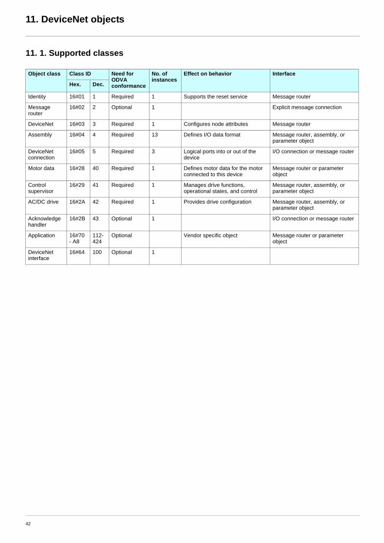
11. 1. Supported classes
Object class Class ID Need for ODVA conformance
No. of instances
Effect on behavior Interface
Hex. Dec.
Identity 16#01 1 Required 1 Supports the reset service Message router
Message router
16#02 2 Optional 1 Explicit message connection
DeviceNet 16#03 3 Required 1 Configures node attributes Message router
Assembly 16#04 4 Required 13 Defines I/O data format Message router, assembly, or parameter object
DeviceNet connection
16#05 5 Required 3 Logical ports into or out of the device
I/O connection or message router
Motor data 16#28 40 Required 1 Defines motor data for the motor connected to this device
Message router or parameter object
Control supervisor
16#29 41 Required 1 Manages drive functions, operational states, and control
Message router, assembly, or parameter object
AC/DC drive 16#2A 42 Required 1 Provides drive configuration Message router, assembly, or parameter object
Acknowledge handler
16#2B 43 Optional 1 I/O connection or message router
Application 16#70 - A8
112-424
Optional Vendor specific object Message router or parameter object
DeviceNet interface
16#64 100 Optional 1
42

11. DeviceNet objects
11. 2. Identity objectThe Identity object provides identification and status information about the drive.
Class code
Class attributes
Instance attributes
(1)Mapped in a word: MSB minor revision (second USINT), LSB major revision (first USINT).Example: 517 = 16#0205 means revision V5.2.
(2)The heartbeat message broadcasts the current state of the device.
Hexadecimal Decimal16#01 1
Attribute ID Access Name Need Data type Value Details
1 Get Revision Opt. UINT 1 —
2 Get Max Instances Opt. UINT 1 1 defined instance
Attribute ID Access Name Need Data type Value Details
1 Get Vendor ID Req. UINT 243 Schneider Automation, Inc [243]if (ATV71) if [Profile] (CHCF) = [Not separ.] (SIM) or [Separate] (SEP) or [I/O] (IO)Square D Company [95]if (ATV58) if [Profile] (CHCF) = [8 serie] (SE8)
2 Get Device type Req. UINT 16#02 AC/DC drive profile
3 Get Product code Req. UINT 1 or 5 1: (ATV58) if [Profile] (CHCF) = [8 serie] (SE8)5: (ATV71) if [Profile] (CHCF) = [Not separ.] (SIM) or [Separate] (SEP) or [I/O] (IO).
4 Get Revision Req. Struct of:USINTUSINT
— Product revision of the drive (1)
5 Get Status Req. WORD — See definition in the table below
6 Get Serial number Req. UDINT — Serial number of the drive
7 Get Product name Req. Struct of:USINTSTRING
— 11 (product name length)“ATV71 Drive”
8 Get State (see Figure on page 45)
Opt. USINT — 0: Non existent1: Device self-testing2: Standby3: Operational4: Major recoverable fault5: Major unrecoverable fault
10 Get/Set Heartbeat interval (2) Opt. USINT 0–255 Interval in seconds between two heartbeat messages. 0: No message.
43

11. DeviceNet objects
Attribute 5–status
Class service
Instance service
(1)Required if the heartbeat interval must be defined.
Bit Definition
0 Owned by master (predefined master/slave connection)
2 Configured (not used)
8 Minor recoverable fault (not used)
9 Minor unrecoverable fault (not used)
10 Major recoverable fault
11 Major unrecoverable fault
Others Reserved 0 (reset to 0)
Service code Service name Need Description
16#0E Get_Attribute_Single Req. Read an attribute
Service code Service name Need Description
16#0E Get_Attribute_Single Req. Read an attribute
16#10 Set_Attribute_Single (1) Write an attribute
16#05 Reset Req. Reset DeviceNet module
44

11. DeviceNet objects
State diagram for the Identity object
Key
Name of the state
NMS LED STATUS
Majorunrecoverablefault
Majorrecoverablefault
Majorrecoverablefault
Flashing red
Operational
Solid green
Standby
Flashing green
Device self testing
Flashing red/green
Nonexistent
Off
Majorunrecoverablefault
Solid red
Desactivated
Activated
Minorfault
Failedtests
Passedtests
PowerApplied
Power loss(from any state)
Identity object reset service
(from any state except Major unrecoverable fault)
Fault corrected
45

11. DeviceNet objects
11. 3. Message router objectThe Message router object is the element through which all the "Explicit messages" objects pass in order to be directed towards the objectsthey are truly destined to.
Class code
Class attributes
Instance attributes
Class service
Instance service
Hexadecimal Decimal16#02 2
Attribute ID Access Name Need Data type Value Details
1 Get Revision Opt. UINT 1 -
2 Get Max instances Opt. UNT 1 1 Defined instance
Attribute ID Access Name Need Data type Value Details
1 Get Object list: Number classes
Opt. Struct of: UINT UINT [ ]
20(codes)
List of supported objects; the first UINT is the number of supported classes; the remaining UINTs are the codes of these classes.
2 Get Number available Opt. UINT 1 Maximum number of simultaneous connections
3 Get Number active Opt. UINT 1 Number of active connections
4 Get Active connections Opt. UINT [ ] 1 List of active connections (referred to with their respective Connection instance ID)
Service code Service name Need Description
16#0E Get_Attribute_Single Req. Read an attribute
Service code Service name Need Description
16#0E Get_Attribute_Single Req. Read an attribute
46
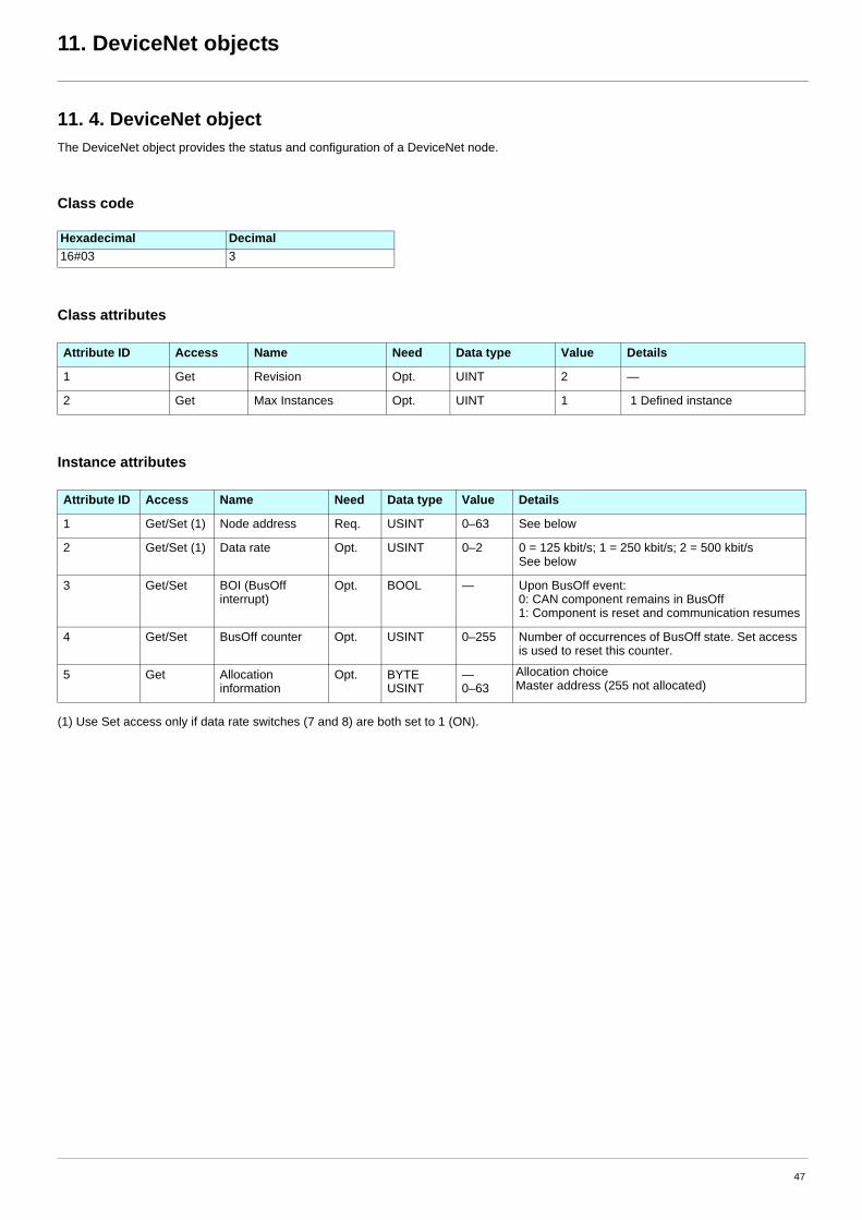
11. DeviceNet objects
11. 4. DeviceNet objectThe DeviceNet object provides the status and configuration of a DeviceNet node.
Class code
Class attributes
Instance attributes
(1) Use Set access only if data rate switches (7 and 8) are both set to 1 (ON).
Hexadecimal Decimal16#03 3
Attribute ID Access Name Need Data type Value Details
1 Get Revision Opt. UINT 2 —
2 Get Max Instances Opt. UINT 1 1 Defined instance
Attribute ID Access Name Need Data type Value Details
1 Get/Set (1) Node address Req. USINT 0–63 See below
2 Get/Set (1) Data rate Opt. USINT 0–2 0 = 125 kbit/s; 1 = 250 kbit/s; 2 = 500 kbit/sSee below
3 Get/Set BOI (BusOff interrupt)
Opt. BOOL — Upon BusOff event:0: CAN component remains in BusOff1: Component is reset and communication resumes
4 Get/Set BusOff counter Opt. USINT 0–255 Number of occurrences of BusOff state. Set access is used to reset this counter.
5 Get Allocation information
Opt. BYTEUSINT
—0–63
Allocation choice Master address (255 not allocated)
47

11. DeviceNet objects
Class service
Instance service
Service code Service name Need Description
16#0E Get_Attribute_Single Req. Read an attribute
Service code Service name Need Description
16#0E Get_Attribute_Single Opt. Read an attribute
16#10 Set_Attribute_Single Opt. Write an attribute
16#4B Allocate Master/Slave Connection Set Opt. Allocation connection master/slave
16#4C Release Master/Slave Connection Set Opt. Release connection master/slave
48

11. DeviceNet objects
11. 5. Assembly objectThe Assembly object binds together the attributes of multiple objects so that information to or from each object can be communicated overa single connection.
Assembly objects are static.
The assemblies in use can be modified through the parameter access of the network configuration tool (RSNetWorx).
The drive needs a power off to take into account a new assembly assignment.
Class code
Class attribute
Instances supported
Instance attributes
(1)Set access is restricted to output instances only (instances 20, 21, 22, 23, 100 and 103).
Class service
Instance service
Hexadecimal Decimal16#04 4
Attribute ID Access Name Need Data type Value Details
1 Get Revision Opt. UINT 2 —
2 Get Max instance Opt. UINT 105 13 defined instances
Instance Name Data size
20 ODVA Basic speed control output 4 bytes
21 ODVA Extended speed control output 4 bytes
22 ODVA Speed and torque control output 6 bytes
23 ODVA Extended speed and torque control output 6 bytes
100 Communication scanner output 8 bytes
103 Allen-Bradley® drive output 4 bytes
70 ODVA Basic speed control input 4 bytes
71 ODVA Extended speed control input 4 bytes
72 ODVA Speed and torque control input 6 bytes
73 ODVA Extended speed and torque control input 6 bytes
101 Communication scanner input 8 bytes
104 Allen-Bradley® drive input 4 bytes
105 Allen-Bradley® drive input with parameters 8 bytes
Attribute ID Access Name Need Data type Value Details
3 Get/Set (1) Data Req.
Service code Service name Need Description
16#0E Get_Attribute_Single Req. Read an attribute
Service code Service name Need Description
16#0E Get_Attribute_Single Req. Read an attribute
16#10 Set_Attribute_Single Opt. Write an attribute
49

11. DeviceNet objects
b Output assembly 100
b Input assembly 101
Note:• For the assignment of the scanner parameters by the drive HMI, refer to chapter 7. Configuring by the drive HMI.
• For monitoring of the scanner parameters by the drive HMI, refer to chapter 10. Diagnostics by the drive HMI.
• For the assignment and monitoring of the scanner parameters by the network configuration software (RSNetWorx ...) , refer to chapter 8. Configuring by a network tool.
Bytes 0 and 1
1st Scanner out parameter [Val Com Scan Out1] (NC1)
Bytes 2 and 3
2nd Scanner out parameter [Val Com Scan Out2] (NC2)
Bytes 4 and 5
3rd Scanner out parameter [Val Com Scan Out3] (NC3)
Bytes 6 and 7
4th Scanner out parameter [Val Com Scan Out4] (NC4)
Bytes 0 and 1
1st Scanner in parameter [Val Com Scan In1] (NM1)
Bytes 2 and 3
2nd Scanner in parameter [Val Com Scan In2] (NM2)
Bytes 4 and 5
3rd Scanner in parameter [Val Com Scan In3] (NM3)
Bytes 6 and 7
4th Scanner in parameter [Val Com Scan In4] (NM4)
50

11. DeviceNet objects
b Output assembly 20
Notes:• Stop mode is configurable by the parameter [Type of stop] (Stt):
- drive HMI menu [1.7 - APPLICATION FUNCT.] (FUn-), sub-menu [STOP CONFIGURATION] (Stt-),- path 16#99/01/02.
• Output assembly 20 controls the drive if the parameter NetCtrl is set to 1 (attribute 5 of Control Supervisor object; path 16#29/01/05, the default setting is 1).
• Output assembly 20 gives the speed setpoint to drive if the parameter NetRef is set to 1 ( attribute 4 of AC/DC Drive object, path 16#2A/01/04, the default setting is 0).
In default setting, output assembly 20 controls the drive but the speed setpoint is via terminals (AI1 or AI2).
The default setting applies each time the connection is closed (Power on of the drive, DeviceNet disconnected from the card).
b Input assembly 70
Byte 0
Bit 7 Bit 6 Bit 5 Bit 4 Bit 3 Bit 2 Bit 1 Bit 0
not used not used not used not used not used Fault reset(active at 1)
not used Run forward0 = Run1 = Stop
Byte 1
Bit 15 Bit 14 Bit 13 Bit 12 Bit 11 Bit 10 Bit 9 Bit 8
not used not used not used not used not used not used not used not used
Bytes 2 and 3
Speed setpoint (RPM)
Byte 0
Bit 7 Bit 6 Bit 5 Bit 4 Bit 3 Bit 2 Bit 1 Bit 0
not used not used not used not used not used Running0 = Stopped1 = Running
not used Faulted0 = No fault1 = Faulted
Byte 1
Bit 15 Bit 14 Bit 13 Bit 12 Bit 11 Bit 10 Bit 9 Bit 8
not used not used not used not used not used not used not used not used
Bytes 2 and 3
Actual speed (RPM)
51

11. DeviceNet objects
b Output assembly 21
Notes:• Stop mode is configurable by the parameter [Type of stop] (Stt):
- drive HMI menu [1.7 - APPLICATION FUNCT.] (FUn-), sub-menu [STOP CONFIGURATION] (Stt-),- path 16#99/01/02.
Byte 0
Bit 7 Bit 6 Bit 5 Bit 4 Bit 3 Bit 2 Bit 1 Bit 0
not used
Network reference
Network control
not used not used Fault Reset(active at 1)
Runreverse
Runforward
0 0 0 0
Control and reference by terminals Stop
0 1 0 1
Control by networkReference by terminals Run forward
1 0 1 0
Control by terminalsReference by network Run reverse
1 1 1 1
Control andReference by network Stop
Byte 1
Bit 15 Bit 14 Bit 13 Bit 12 Bit 11 Bit 10 Bit 9 Bit 8
not used not used not used not used not used not used not used not used
Bytes 2 and 3
Speed setpoint (RPM)
52

11. DeviceNet objects
b Input assembly 71
Byte 0
Bit 7 Bit 6 Bit 5 Bit 4 Bit 3 Bit 2 Bit 1 Bit 0
At reference Reference from network
Control from network Ready Running
reverseRunning forward Warning Faulted
0 0 0 0 0 0 0 0
Speed reference not
reached
Control and reference by terminals Not ready Stopped No warning Not faulted
0 1 1 0 0 1 1
Control by networkReference by terminals Ready Running forward Warning Faulted
1 1 0 1 0
Speed referencereached
Control by terminalsReference by network Running reverse
1 1 1 1
Control and referencefrom network Stopped
Byte 1
Bit 15 Bit 14 Bit 13 Bit 12 Bit 11 Bit 10 Bit 9 Bit 8
Drive state (see Control supervisor state transition diagramm, page 66)(0 = Vendor Specific, 1 = Startup, 2 = Not_Ready, 3 = Ready, 4 = Enabled, 5 = Stopping, 6 = Fault_Stop, 7 = Faulted)
Bytes 2 and 3
Actual speed (RPM)
53

11. DeviceNet objects
b Output assembly 22
Notes:• Stop mode is configurable by the parameter [Type of stop] (Stt):
- drive HMI menu [1.7 - APPLICATION FUNCT.] (FUn-), sub-menu [STOP CONFIGURATION] (Stt-),- path 16#99/01/02.
• Output assembly 22 controls the drive if the parameter NetCtrl is set to 1 (attribute 5 of Control Supervisor object; path 16#29/01/05, the default setting is 1).
• Output assembly 22 gives the speed setpoint to drive if the parameter NetRef is set to 1 ( attribute 4 of AC/DC Drive object, path 16#2A/01/04, the default setting is 0).
In default setting, output assembly 22 controls the drive but the speed setpoint is via terminals (AI1 or AI2).
The default setting applies each time the connection is closed (Power on of the drive, DeviceNet disconnected from the card).
b Input assembly 72
Byte 0
Bit 7 Bit 6 Bit 5 Bit 4 Bit 3 Bit 2 Bit 1 Bit 0
not used not used not used not used not used Fault reset(active at 1)
not used Run forward0 = Stop1 = Run
Byte 1
Bit 15 Bit 14 Bit 13 Bit 12 Bit 11 Bit 10 Bit 9 Bit 8
not used not used not used not used not used not used not used not used
Bytes 2 and 3
Speed setpoint (RPM)
Bytes 4 and 5
Torque setpoint (Nm)
Byte 0
Bit 7 Bit 6 Bit 5 Bit 4 Bit 3 Bit 2 Bit 1 Bit 0
not used not used not used not used not used Running0 = Stopped1 = Running
not used Faulted0 = No fault1 = Faulted
Byte 1
Bit 15 Bit 14 Bit 13 Bit 12 Bit 11 Bit 10 Bit 9 Bit 8
not used not used not used not used not used not used not used not used
Bytes 2 and 3
Actual speed (RPM)
Bytes 4 and 5
Actual torque (Nm)
54
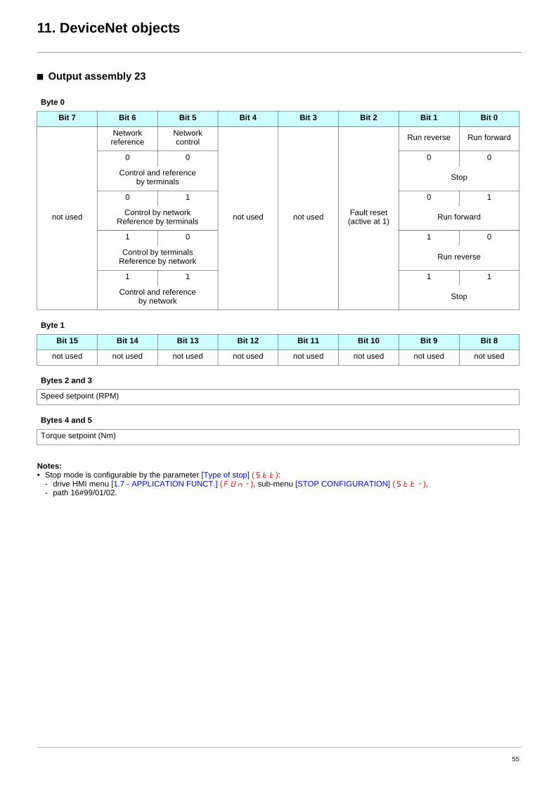
11. DeviceNet objects
b Output assembly 23
Notes:• Stop mode is configurable by the parameter [Type of stop] (Stt):
- drive HMI menu [1.7 - APPLICATION FUNCT.] (FUn-), sub-menu [STOP CONFIGURATION] (Stt-),- path 16#99/01/02.
Byte 0
Bit 7 Bit 6 Bit 5 Bit 4 Bit 3 Bit 2 Bit 1 Bit 0
not used
Networkreference
Network control
not used not used Fault reset (active at 1)
Run reverse Run forward
0 0 0 0
Control and reference by terminals Stop
0 1 0 1
Control by network Reference by terminals Run forward
1 0 1 0
Control by terminalsReference by network Run reverse
1 1 1 1
Control and reference by network Stop
Byte 1
Bit 15 Bit 14 Bit 13 Bit 12 Bit 11 Bit 10 Bit 9 Bit 8
not used not used not used not used not used not used not used not used
Bytes 2 and 3
Speed setpoint (RPM)
Bytes 4 and 5
Torque setpoint (Nm)
55

11. DeviceNet objects
b Input assembly 73
Byte 0
Bit 7 Bit 6 Bit 5 Bit 4 Bit 3 Bit 2 Bit 1 Bit 0
At reference Reference from network
Control from network Ready Running
reverseRunning forward Warning Faulted
0 0 0 0 0 0 0 0
Speed reference not
reached
Control and referencefrom terminals Not ready Stopped No warning Not faulted
0 1 1 0 1 1 1
Control from network Reference from terminals Ready Running forward Warning Faulted
1 1 0 1 0
Speed reference reached
Control from terminalsReference from network Running reverse
1 1 1 1
Control and referencefrom network Stopped
Byte 1
Bit 15 Bit 14 Bit 13 Bit 12 Bit 11 Bit 10 Bit 9 Bit 8
Drive state (see figure Control supervisor state transition diagram, page 66)
( 0 = Vendor Specific, 1 = Startup, 2 = Not_Ready, 3 = Ready, 4 = Enabled, 5 = Stopping, 6 = Fault_Stop, 7 = Faulted )
Bytes 2 and 3
Actual speed (RPM)
Bytes 4 and 5
Actual torque (Nm)
56

11. DeviceNet objects
b Output assembly 103
Notes:• Stop mode is configurable by the parameter [Type of stop] (Stt):
- drive HMI menu [1.7 - APPLICATION FUNCT.] (FUn-), sub-menu [STOP CONFIGURATION] (Stt-),- path 16#99/01/02.
• Output assembly 22 controls the drive if the parameter NetCtrl is set to 1 (attribute 5 of Control Supervisor object; path 16#29/01/05, the default setting is 1).
• Output assembly 22 gives the speed setpoint to drive if the parameter NetRef is set to 1 ( attribute 4 of AC/DC Drive object, path 16#2A/01/04, the default setting is 0).
In default setting, output assembly 22 controls the drive but the speed setpoint is via terminals (AI1 or AI2).
The default setting applies each time the connection is closed (Power on of the drive, DeviceNet disconnected from the card).
Byte 0
Bit 7 Bit 6 Bit 5 Bit 4 Bit 3 Bit 2 Bit 1 Bit 0
not used not used
Direction
Clear faults(active at 1) not used
Start Stop
0 0
Active on rising edge
(0 to 1)
Active onlevel(at 1)
Hold direction
0 1
Forward command
1 0
Reverse command
1 1
Hold direction
Byte 1
Bit 15 Bit 14 Bit 13 Bit 12 Bit 11 Bit 10 Bit 9 Bit 8
not used
Reference select
not used not used not used not used
0 0 0
Hold reference select
0 0 1
Reference by terminals (AI1 or AI2)
0 1 0
Reference by network (DeviceNet)
0 1 1
Preset speed 3 (SP3)
1 0 0
Preset speed 4 (SP4)
1 0 1
Preset speed 5 (SP5)
1 1 0
Preset speed 6 (SP6)
1 1 1
Preset speed 7 (SP7)
Bytes 2 and 3
Scaled speed setpointUnsigned, 0 to 32 767. 32 767= parameter [High speed] (HSP), path 16#70/01/69
57

11. DeviceNet objects
b Input assembly 104
Note: When the value of Reference source (bits 12, 13, 14 and 15) is Preset speed p (SPp) it means that the corresponding commands isgiven by the assembly 103 via Reference select (bits 12,13 and 14) (not by the terminals).
Byte 0
Bit 7 Bit 6 Bit 5 Bit 4 Bit 3 Bit 2 Bit 1 Bit 0
Fault not used Decelerating Accelerating
Actual direction
1=Forward0=Reverse
Command direction
1=Forward0=Reverse
Running Enabled
Byte 1
Bit 15 Bit 14 Bit 13 Bit 12 Bit 11 Bit 10 Bit 9 Bit 8
Reference source Control source At speed
0 0 0 0 0 0 0
Control from terminals
0 0 0 1 0 0 1
Control from network
0 0 1 0 0 1 0
not used 0 1 1
0 0 1 1 1 0 0
Preset speed 3 (SP3) 1 0 1
0 1 0 0 1 1 0
Preset speed 4 (SP4) 1 1 1
0 1 0 1 not used
Preset speed 5 (SP5)
0 1 1 0
Preset speed 6 (SP6)
0 1 1 1
Preset speed 7 (SP7)
1 0 0 0
Reference from terminals (AI1 or AI2)
1 0 0 1
Reference from network (DeviceNet)
1 0 1 0
1 0 1 1
1 1 0 0
1 1 0 1
1 1 1 0
not used
1 1 1 1
No reference source defined
Bytes 2 and 3
Actual speed scaledUnsigned, 0 to 32 767. 32 767= parameter [High speed] (HSP), path 16#70/01/69
58

11. DeviceNet objects
b Input assembly 105
Byte 0Bit 7 Bit 6 Bit 5 Bit 4 Bit 3 Bit 2 Bit 1 Bit 0
Fault not used Decelerating Accelerating
Actualdirection
1=Forward0=Reverse
Commanddirection
1=Forward0=Reverse
Running Enabled
Byte 1Bit 15 Bit 14 Bit 13 Bit 12 Bit 11 Bit 10 Bit 9 Bit 8
Reference source Control source At speed
0 0 0 0 0 0 0
not used Control from terminals
0 0 0 1 0 0 1
Preset speed 1 (SP1) Control from network
0 0 1 0 0 1 0
Preset speed 2 (SP2) 0 1 1
0 0 1 1 1 0 0
Preset speed 3 (SP3) 1 0 1
0 1 0 0 1 1 0
Preset speed 4 (SP4) 1 1 1
0 1 0 1 not used
Preset speed 5 (SP5)
0 1 1 0
Preset speed 6 (SP6)
0 1 1 1
Preset speed 7 (SP7)
1 0 0 0
Reference from terminals (AI1 or AI2)
1 0 0 1
Reference from network (DeviceNet)
11111
00111
11001
01010
not used
1 1 1 1
No reference source defined
Bytes 2 and 3Actual speed scaledUnsigned, 0 to 32 767. 32 767= parameter [High speed] (HSP), path 16#70/01/69
Bytes 4 and 5First extended monitoring parameter (see DeviceNet interface object page 70)
Bytes 6 and 7Second extended monitoring parameter (see DeviceNet interface object page 70)
59

11. DeviceNet objects
11. 6. Connection objectClass code
Class attributes
(1)Only instances 1 (explicit message), 2 (polled I/O message), and 4 (change of state/cyclic message) are supported. Instance 3 (bit strobe) is not supported.
Attributes of instance 1—Explicit message instance
Refer to DeviceNet specification for more information.
Hexadecimal Decimal16#05 5
Attribute ID Access Name Need Data type Value Details
1 Get Revision Opt. UINT 1 —
2 Get Max instances Opt. UINT 4 3 defined instances (1)
Attribute ID Access Name Need Data type Value Details
1 Get State Req. USINT — 0 : Non-existent3 : Established5 : Deferred Delete
2 Get Instance_type Req. USINT 0 Explicit Message
3 Get TransportClass_trigger Req. BYTE 16#83 Class 3 server
4 Get Produced_connection_id Req. UINT 10xxxxxx011 xxxxxx = Node address
5 Get Consumed_connection_id Req. UINT 10xxxxxx100 xxxxxx = Node address
6 Get Initial_comm_characteristics Req. BYTE 16#21 Explicit messaging via Group 2
7 Get Produced_connection_size Req. UINT 36 Produced data maximum size (in bytes)
8 Get Consumed_connection_size Req. UINT 36 Consumed data maximum size (in bytes)
9 Get/Set Expected_packet_rate Req. UINT 2500 2.5 sec. (TimeOut)
12 Get/Set Watchdog_timeout_action Req. USINT 1 or 3 1 : Auto-Delete 3 : Deferred Delete (Default)
13 Get Produced connection path length Req. UINT 0 Length of attribute 14 data
14 Get Produced connection path Req. Array of UINT Null Empty
15 Get Consumed connection path length Req. UINT 0 Length of attribute 16 data
16 Get Consumed connection path Req. Array of UINT Null Empty
60

11. DeviceNet objects
Attributes of instance 2—Polled I/O message instance
(1)Assembly assignment should not be modified in a running application. If you Set any one of the values displayed in the "Value" column, it will be saved in EEPROM and then used at each power-up. Any other value will not be saved.
(2)0 and 1: when the drive is disconnected from the network a DeviceNet fault occurs. In factoring settings the DeviceNet fault triggers a fault [Com. network] (CnF) and a free wheel stop.2: The DeviceNet fault is automatically reset (drive immediately restarts when RUN command is applied).
Attribute ID Access Name Need Data type Value Details
1 Get State Req. USINT — 0: Non-existent1: Configuring3: Established4: TimeOut
2 Get Instance_type Req. USINT 1 I/O Message
3 Get TransportClass_trigger Req. BYTE 16# 83 Class 3 server
4 Get Produced_connection_id Req. UINT 01111xxxxxx xxxxxx = Node address
5 Get Consumed_connection_id Req. UINT 10xxxxxx101 xxxxxx = Node address
6 Get Initial_comm_characteristics Req. BYTE 16# 01 Group 1 / Group 2
7 Get Produced_connection_size Req. UINT 4, 6, or 8 Size of data produced
8 Get Consumed_connection_size Req. UINT 4, 6, or 8 Size of data consumed
9 Get/Set Expected_packet_rate Req. UINT — Exchange frequency (ms)
12 Get/Set Watchdog_timeout_action Req. USINT 0, 1, or 2 (2) 0: Transition to TimeOut1: Auto-Delete2: Auto-Reset
13 Get Produced_connection_path length Req. UINT 8 Default: 8 bytes
14 Get/Set (1)
Produced_connection_path Req. Array of UINT
16# 20 04 24 46 30 0316# 20 04 24 47 30 0316# 20 04 24 48 30 0316# 20 04 24 49 30 0316# 20 04 24 65 30 0316# 20 04 24 68 30 0316# 20 04 24 69 30 03
Input assembly (Default : Instance 101, 16# 20 04 24 65 30 03)
15 Get Consumed_connection_path length Req. UINT 8 Default: 8 bytes
16 Get/Set (1)
Consumed_connection_path Req. Array of UINT
16# 20 04 24 14 30 0316# 20 04 24 15 30 0316# 20 04 24 16 30 0316# 20 04 24 17 30 0316# 20 04 24 64 30 0316# 20 04 24 67 30 03
Output assembly(Default : Instance 100, 16# 20 04 24 64 30 03)
17 Get/Set Production_inhibit_time Cond. UINT 0 Minimum time between 2 data productions. Undefined
61

11. DeviceNet objects
Attributes of instance 4—Change of state/cyclic message instance
(1)Assembly assignment should not be modified in a running application.If you Set any one of the values displayed in the "Value" column, it will be saved in EEPROM and then used at each power-up. Any other value will not be saved.
(2)To ensure a DeviceNet fault (and by default [Network fault] (CnF)) in case of time out, configure "Polled I/O".
AttributeID
Access Name Need Data type
Value Details
1 Get State Req. USINT — 0: Non-existent1: Configuring3: Established4: TimeOut
2 Get Instance_type Req. USINT 1 I/O Message
3 Get TransportClass_trigger Req. BYTE 16# X2 Class 2 ClientCos:16# 12 - Cyclic:16# 02
4 Get Produced_connection_id Req. UINT 01101xxxxxx xxxxxx = Node address
5 Get Consumed_connection_id Req. UINT 10xxxxxx101 xxxxxx = Node address
6 Get Initial_comm_characteristics Req. BYTE 16# 01 Group 1 / Group 2
7 Get Produced_connection_size Req. UINT 4, 6, or 8 Size of data produced
8 Get Consumed_connection_size Req. UINT 0 Size of data consumed
9 Get/Set Expected_packet_rate Req. UINT — Exchange frequency (ms)
12 Get/Set Watchdog_timeout_action Req. USINT 0, 1, or 2 (2) 0: Transition to TimeOut1: Auto-Delete 2: Auto-Reset
13 Get Produced_connection_path_length Req. UINT 8 Default: 8 bytes
14 Get/Set (1)
Produced_connection_path Req. Array of UINT
16# 20 04 24 46 30 0316# 20 04 24 47 30 0316# 20 04 24 48 30 0316# 20 04 24 49 30 0316# 20 04 24 65 30 0316# 20 04 24 68 30 0316# 20 04 24 69 30 03
Input assembly (Default : Instance 101,16# 20 04 24 65 30 03)
15 Get Consumed_connection_path_length Req. UINT 8 Default: 8 bytes
16 Get/Set(1)
Consumed_connection_path Req. Array of UINT
16# 20 2B 24 01 30 03 Output assembly:The first and only one instance of the Acknowledge handler object (Class ID 16#2B)
17 Get/Set Production_inhibit_time Cond. UINT 0 Minimum time between 2 data productions.Undefined
62

11. DeviceNet objects
Class service
Instance service
Service code Service name Need Description
16#08 Create Opt. Instantiation of a connection
16#0E Get_Attribute_Single Req. Read an attribute
Service code Service name Need Description
16#0E Get_Attribute_Single Req. Read an attribute
16#10 Set_Attribute_Single Opt. Write an attribute
16#05 Reset Opt. Reset Inactivity/Watchdog timer
63
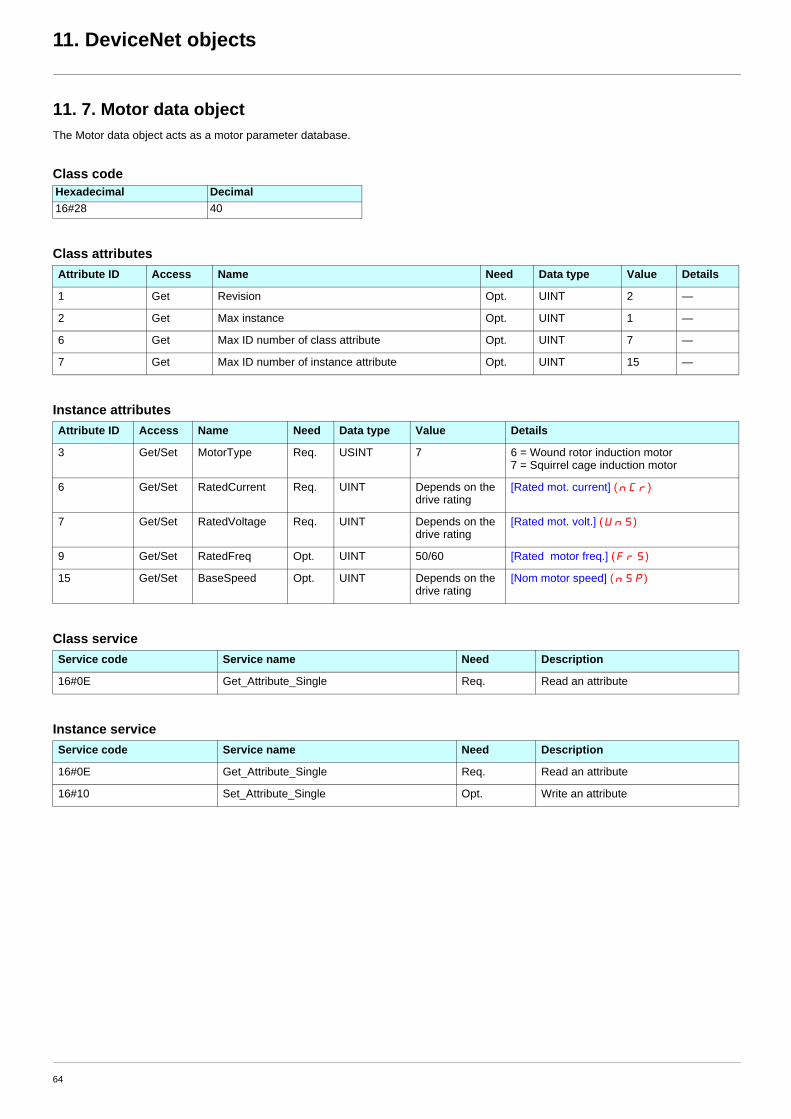
11. DeviceNet objects
11. 7. Motor data objectThe Motor data object acts as a motor parameter database.
Class code
Class attributes
Instance attributes
Class service
Instance service
Hexadecimal Decimal16#28 40
Attribute ID Access Name Need Data type Value Details
1 Get Revision Opt. UINT 2 —
2 Get Max instance Opt. UINT 1 —
6 Get Max ID number of class attribute Opt. UINT 7 —
7 Get Max ID number of instance attribute Opt. UINT 15 —
Attribute ID Access Name Need Data type Value Details
3 Get/Set MotorType Req. USINT 7 6 = Wound rotor induction motor7 = Squirrel cage induction motor
6 Get/Set RatedCurrent Req. UINT Depends on the drive rating
[Rated mot. current] (nCr)
7 Get/Set RatedVoltage Req. UINT Depends on the drive rating
[Rated mot. volt.] (UnS)
9 Get/Set RatedFreq Opt. UINT 50/60 [Rated motor freq.] (FrS)
15 Get/Set BaseSpeed Opt. UINT Depends on the drive rating
[Nom motor speed] (nSP)
Service code Service name Need Description
16#0E Get_Attribute_Single Req. Read an attribute
Service code Service name Need Description
16#0E Get_Attribute_Single Req. Read an attribute
16#10 Set_Attribute_Single Opt. Write an attribute
64

11. DeviceNet objects
11. 8. Control supervisor objectThe Control supervisor object models the functions for managing all devices within the hierarchy of motor control devices.
Class code
Class attributes
Instance attributes
Class service
Instance service
Hexadecimal Decimal16#29 41
Attribute ID Access Name Need Data type Value Details
1 Get Revision Opt. UINT 2 —
2 Get Max instance Opt. UINT 1 —
6 Get Max ID number of class attribute Opt. UINT 7 —
7 Get Max ID number of instance attribute Opt. UINT 17 —
Attribute ID Access Name Need Data type Details
3 Get/Set Run Fwd Req. BOOL On an edge (0 V1)
4 Get/Set Run Rev Opt. BOOL On an edge (0 V1)
5 Get/Set NetCtrl Opt. BOOL 0: Local Control (Channel 1)1: Network Control (default)
6 Get State Opt. USINT 0 = Vendor Specific, 1 = Startup, 2 = Not_Ready, 3 = Ready, 4 = Enabled, 5 = Stopping, 6 = Fault_Stop, 7 = Faulted
7 Get Running Fwd Req. BOOL
8 Get Running Rev Opt. BOOL
9 Get Ready Opt. BOOL
10 Get Faulted Req. BOOL
12 Get/Set FaultRst Req. BOOL Fault reset (0 V1)
13 Get FaultCode Opt. UINT Refer to the Communication parameters manual: DSP402 fault code (Errd)
15 Get CtrlFromNet Opt. BOOL 0 = Local Control; 1 = Network Control
16 Get/Set DNFaultMode Opt. USINT Action on loss of DeviceNet command:0 = DeviceNet fault; 1 = Ignored
17 Get/Set ForceFault/Trip Opt. BOOL Force a DeviceNet fault (0 V1)
Service Code Service name Need Description
16#0E Get_Attribute_Single Req. Read an attribute
Service Code Service name Need Description
16#0E Get_Attribute_Single Req. Read an attribute
16#10 Set_Attribute_Single Req. Write an attribute
16#05 Reset Req. Drive reset
65

11. DeviceNet objects
Control supervisor state transition diagram
Non-Existent
Startup
Switch off
Switch on
Not_Ready
Ready
Fault detected
Main power on
Enabled
Stopping
Stop
Run
Initialization complete
Stop complete
Fault detected
Fault ResetFaulted
Fault_Stop
Fault detected
Fault stop complete
Main power off
Reset Main power off
66

11. DeviceNet objects
11. 9. AC/DC Drive ObjectThe AC/DC Drive object models the functions (such as torque control and speed ramp) that are specific to drives.
Class code
Class attributes
Instance attributes
Class service
Instance service
Hexadecimal Decimal16#2A 42
Attribute ID Access Name Need Data Type Value Details
1 Get Revision Opt. UINT 1 —
2 Get Max instance Opt. UINT 1 —
6 Get Max ID number of class attribute Opt. UINT 7 —
7 Get Max ID number of instance attribute Opt. UINT 21 —
Attribute ID Access Name Need Data type Details
3 Get AtReference Opt. BOOL
4 Get/Set NetRef (1) Req. BOOL 0: Local speed setpoint (AI1 or AI2)1: Speed setpoint via the network
5 Get/Set NetProc Opt. BOOL Not handled
6 Get/Set Drive mode Req. USINT 1: Open loop2: Closed loop (FVC)
7 Get SpeedActual Req. INT Output speed (rFrd)
8 Get/Set SpeedRef Req. INT Speed setpoint (LFrd)
9 Get CurrentActual Opt. INT Motor current (LCr)
10 Get/Set CurrentLimit Opt. INT [Mot. therm. current] (ItH)
11 Get TorqueActual Opt. INT Output torque (Otrn)
12 Get/Set TorqueRef Opt. INT Torque setpoint (LtCr)
18 Get/Set AccelTime Opt. UINT Acceleration time (ACCd)
19 Get/Set DecelTime Opt. UINT Deceleration time (dECd)
20 Get/Set LowSpdLimit Opt. UINT Parameter [Low speed] (LSP) converted in RPM
21 Get/Set HighSpdLimit Opt. UINT Parameter [High speed] (HSP) converted in RPM
Service code Service name Need Description
16#0E Get_Attribute_Single Req. Read an attribute
Service code Service name Need Description
16#0E Get_Attribute_Single Req. Read an attribute
16#10 Set_Attribute_Single Opt. Write an attribute
67

11. DeviceNet objects
11. 10. Acknowledge handler objectThe acknowledge handler object directs the acknowledgment of messages received.
Class code
Class attributes
Instance attributes
Class service
Instance service
Hexadecimal Decimal16#2B 43
Attribute ID Access Name Need Data type Value Details
1 Get Revision Opt. UINT 1 —
2 Get Max instance Opt. UINT 1 —
Attribute ID Access Name Need Data type Value Details
1 Get/Set Acknowledge timer Req. UINT 16 Default: 16 ms
2 Get/Set Retry limit Req. USINT 1 —
3 Get/Set COS producing connection instance Req. UINT 4 Assembly
Service code Service name Need Description
16#0E Get_Attribute_Single Req. Read an attribute
Service code Service name Need Description
16#0E Get_Attribute_Single Req. Read an attribute
16#10 Set_Attribute_Single Req. Write an attribute
68

11. DeviceNet objects
11. 11. Application objectsClass code
Altivar parameters pathThe Altivar parameters are grouped in classes.Each application class has only 1 instance.Each instance groups 200 parameters.Each attribute in an instance relates to a parameter.
The first parameter registered in the first application class (class code: 16#70 = 112) has the logical address 3000.
Examples:
Refer to the Communication parameters manual.
Class attributes
Instance attributes
Note: Depending on the parameter, write access may be prohibited. Refer to the Communication parameters manual for more information.
Class service
Instances service
Hexadecimal Decimal16#70 to 16#A8 112 to 424
Logical address Path Hexadecimal Path decimal3 000 16# 70 / 01 / 01 112 / 1 / 13 100 16# 70 / 01 / 65 112 / 1 / 1013 200 16# 71 / 01 / 01 113 / 1 / 1
64 318 16# A2 / 1 / 77 418 / 1 / 119
Attribute ID Access Name Need Data type Value
1 Get Revision Opt. UINT 1
2 Get Max instance Opt. UINT 1
6 Get Max ID number of class attribute Opt. UINT 7
7 Get Max ID number of instance attribute Opt. UINT X
Attribute ID Access Name Data type Value
1 Get/Set First parameter of the class UINT / USINT Value returned by the drive
... ... ... ... ...
X Get/Set Last parameter of the class UINT / USINT Value returned by the drive
Service code Service name Need Description
16#0E Get_Attribute_Single Req. Read an attribute
Service code Service name Need Description
16#0E Get_Attribute_Single Req. Read an attribute
116#0 Set_Attribute_Single Opt. Write an attribute
69

11. DeviceNet objects
11. 12. DeviceNet interface object
Class code
Class attributes
Instances attributes
(1)Any Set access to one of these parameters triggers the save in EEPROM for future use. In addition, the new value is immediately applied to the drive if the corresponding Connection Object (Polled I/O Message or Change of State/Cyclic Message, i.e. Class ID 16#80 Instance #2 or #4) is not in "Established" state. Otherwise, the drive must be restarted to apply the new value.
Hexadecimal Decimal16#64 100
Attribute ID Access Name Need Data type Value
1 Get Revision Opt. UINT 1
2 Get Max instance Opt. UINT 1
6 Get Max ID number of class attribute Opt. UINT 7
7 Get Max ID number of instance attribute Opt. UINT 9
AttribueID
Access Name Data type Details
1 Get/Set(1)
Polling production instance assembly USINT 0 : instance 701 : instance 712 : instance 1043 : instance 1054 : instance 725 : instance 736 : instance 101 (default)
2 Get/Set(1)
Polling consumption instance assembly USINT 0 : instance 201 : instance 212 : instance 1033 : instance 224 : instance 235 : instance 100 (default)
3 Get/Set(1)
Change of state/Cyclic production instance assembly USINT 0 : instance 701 : instance 712 : instance 1043 : instance 1054 : instance 725 : instance 736 : instance 101 (default)
4 Get [Network fault] (CnF) USINT 0 : no fault1 : user forced fault2 : duplicate Node Address3 : CAN FIFO RX Error4 : CAN FIFO TX Error5 : CAN OverRun6 : CAN send Error 7 : CAN Bus Off8 : Control Time Out9 : Acknowledge Error
5 Get Software revision of the DeviceNet card UINT Ex : 16# 1109 = V1.1ie09
6 Get/Set Attribute of first extended monitoring parameter (input assembly 105) USINT 0 : not configured
7 Get/Set Attibute of second extended monitoring parameter (input assembly 105) USINT
8 Get/Set Class of first extended monitoring parameter (input assembly 105) USINT 0 : not configured
9 Get/Set Class of second extended monitoring parameter (input assembly 105) USINT
70

11. DeviceNet objects
Class service
Instance services
Service code Service name Need Description
16#0E Get_Attribute_Single Req. Read an attribute
Service code Service name Need Description
16#0E Get_Attribute_Single Req. Read an attribute
16#10 Set_Attribute_Single Opt. Write an attribute
71

2005-05
atv71_DeviceNet_EN_V1