Embed Size (px)
Citation preview
DF–20 DIFFERENTIAL – FRONT DIFFERENTIAL CARRIER ASSEMBLY
DF
REMOVAL1. DISCONNECT CABLE FROM NEGATIVE BATTERY
TERMINAL2. REMOVE FRONT WHEEL3. REMOVE NO.1 ENGINE UNDER COVER SUB-
ASSEMBLY4. REMOVE REAR ENGINE UNDER COVER ASSEMBLY5. DRAIN DIFFERENTIAL OIL6. REMOVE FRONT PROPELLER SHAFT ASSEMBLY
(See page PR-2)7. SEPARATE SPEED SENSOR FRONT LH (See page
DS-3)8. SEPARATE FRONT SPEED SENSOR RH
HINT:Use the same procedure as for the RH side.
9. REMOVE FRONT AXLE HUB GREASE CAP LH (See page DS-3)
10. REMOVE FRONT AXLE HUB GREASE CAP RHHINT:Use the same procedure as for the RH side.
11. SEPARATE TIE ROD END SUB-ASSEMBLY LH (See page DS-3)
12. SEPARATE TIE ROD END SUB-ASSEMBLY RH13. SEPARATE FRONT LOWER BALL JOINT
ATTACHMENT (See page DS-4)14. REMOVE FRONT AXLE HUB NUT LH (See page DS-
3)15. REMOVE FRONT AXLE HUB NUT RH
HINT:Use the same procedure as for the RH side.
16. REMOVE FRONT DRIVE SHAFT ASSEMBLY LH (See page DS-4)
17. REMOVE FRONT DRIVE SHAFT ASSEMBLY RHHINT:Use the same procedure as for the RH side.
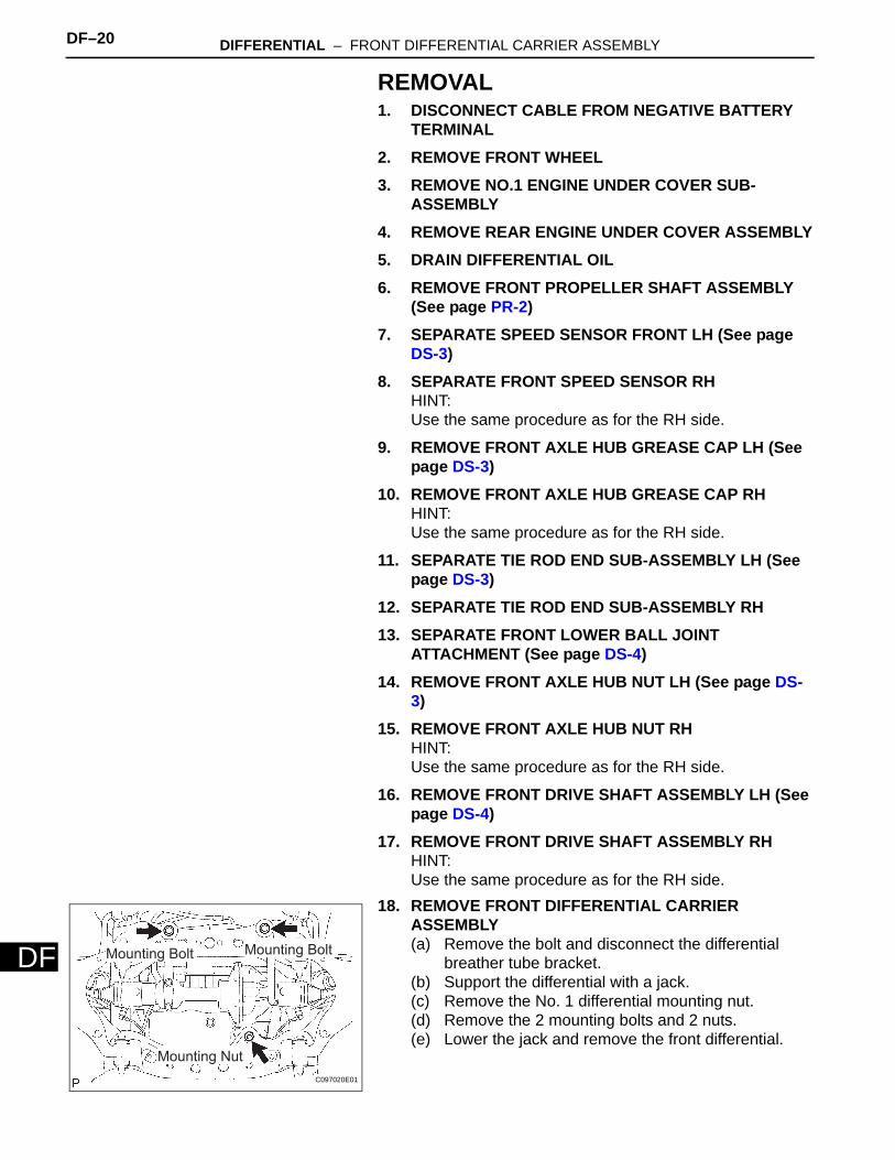
18. REMOVE FRONT DIFFERENTIAL CARRIER ASSEMBLY(a) Remove the bolt and disconnect the differential
breather tube bracket.(b) Support the differential with a jack.(c) Remove the No. 1 differential mounting nut.(d) Remove the 2 mounting bolts and 2 nuts.(e) Lower the jack and remove the front differential.
Mounting Bolt Mounting Bolt
Mounting Nut
C097020E01
DIFFERENTIAL – FRONT DIFFERENTIAL CARRIER ASSEMBLY DF–21
F
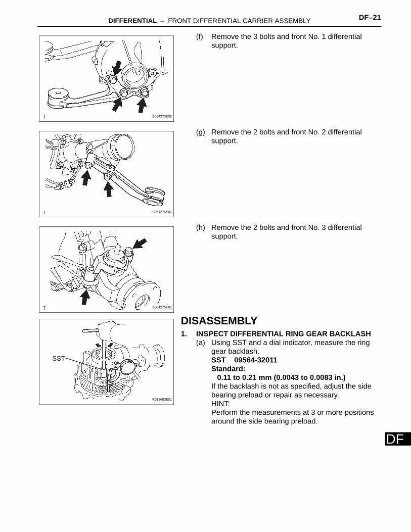
D(f) Remove the 3 bolts and front No. 1 differential support.
(g) Remove the 2 bolts and front No. 2 differential support.
(h) Remove the 2 bolts and front No. 3 differential support.
DISASSEMBLY1. INSPECT DIFFERENTIAL RING GEAR BACKLASH
(a) Using SST and a dial indicator, measure the ring gear backlash.SST 09564-32011Standard:
0.11 to 0.21 mm (0.0043 to 0.0083 in.)If the backlash is not as specified, adjust the side bearing preload or repair as necessary.HINT:Perform the measurements at 3 or more positions around the side bearing preload.
B084273E02
B084274E01
B084275E01
SST
R012683E01

DF–22 DIFFERENTIAL – FRONT DIFFERENTIAL CARRIER ASSEMBLY
DF
2. INSPECT FRONT DRIVE PINION COMPANION FLANGE SUB-ASSEMBLY(a) Using a dial indicator, measure the runout of the
companion flange vertically and laterally.Maximum runout
If the runout is greater than the maximum, replace the companion flange.
3. INSPECT DRIVE PINION PRELOAD(a) Using a torque wrench, measure the preload of the
backlash between the drive pinion and ring gear.HINT:Bolts without torque specifications are shown in the service data (see page SS-43).
4. INSPECT TOTAL PRELOAD(a) Using a torque wrench, measure the preload with
the teeth of the drive pinion and ring gear in contact.HINT:Bolts without torque specifications are shown in the service data (see page SS-43).If necessary, disassemble and inspect the differential.
5. REMOVE DIFFERENTIAL VACUUM ACTUATOR ASSEMBLY(a) Remove the 4 bolts.(b) Using a hammer, pry out the actuator from the
differential tube.
6. REMOVE FRONT DIFFERENTIAL TUBE ASSEMBLY(a) Remove the 4 bolts.(b) Using a plastic-faced hammer, tap out the
differential tube.
Vertical Runout Lateral Runout
30 mm (1.18 in.) F001237E05
Runout Maximum
Vertical runout 0.10 mm (0.0039 in.)
Lateral runout 0.10 mm (0.0039 in.)
FA01158E01
FA01158E01
G023135E01
C097021E01
DIFFERENTIAL – FRONT DIFFERENTIAL CARRIER ASSEMBLY DF–23
F
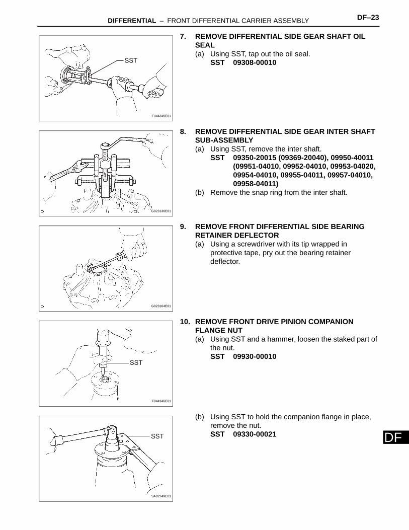
D7. REMOVE DIFFERENTIAL SIDE GEAR SHAFT OIL SEAL(a) Using SST, tap out the oil seal.
SST 09308-00010
8. REMOVE DIFFERENTIAL SIDE GEAR INTER SHAFT SUB-ASSEMBLY(a) Using SST, remove the inter shaft.
SST 09350-20015 (09369-20040), 09950-40011 (09951-04010, 09952-04010, 09953-04020, 09954-04010, 09955-04011, 09957-04010, 09958-04011)
(b) Remove the snap ring from the inter shaft.
9. REMOVE FRONT DIFFERENTIAL SIDE BEARING RETAINER DEFLECTOR(a) Using a screwdriver with its tip wrapped in
protective tape, pry out the bearing retainer deflector.
10. REMOVE FRONT DRIVE PINION COMPANION FLANGE NUT(a) Using SST and a hammer, loosen the staked part of
the nut.SST 09930-00010
(b) Using SST to hold the companion flange in place, remove the nut.SST 09330-00021
SST
F044345E01
G023136E01
G023164E01
SST
F044346E01
SST
SA02349E03
DF–24 DIFFERENTIAL – FRONT DIFFERENTIAL CARRIER ASSEMBLY
DF
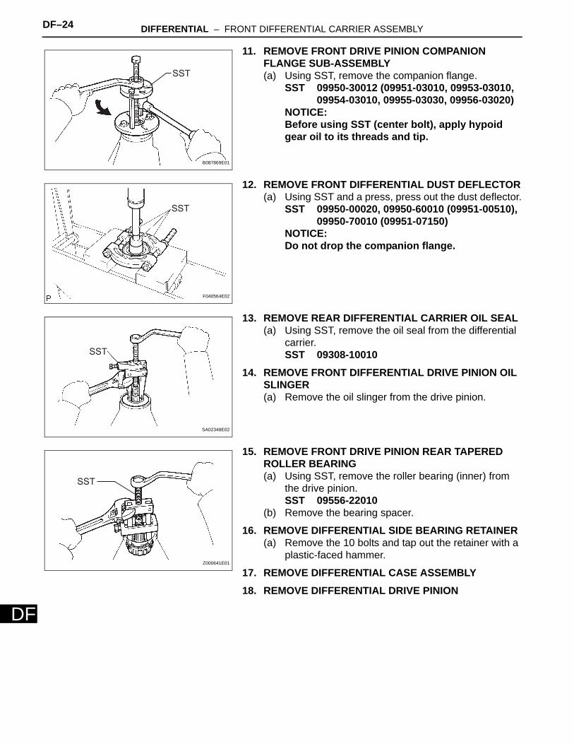
11. REMOVE FRONT DRIVE PINION COMPANION FLANGE SUB-ASSEMBLY(a) Using SST, remove the companion flange.
SST 09950-30012 (09951-03010, 09953-03010, 09954-03010, 09955-03030, 09956-03020)
NOTICE:Before using SST (center bolt), apply hypoid gear oil to its threads and tip.
12. REMOVE FRONT DIFFERENTIAL DUST DEFLECTOR(a) Using SST and a press, press out the dust deflector.
SST 09950-00020, 09950-60010 (09951-00510), 09950-70010 (09951-07150)
NOTICE:Do not drop the companion flange.
13. REMOVE REAR DIFFERENTIAL CARRIER OIL SEAL(a) Using SST, remove the oil seal from the differential
carrier.SST 09308-10010
14. REMOVE FRONT DIFFERENTIAL DRIVE PINION OIL SLINGER(a) Remove the oil slinger from the drive pinion.
15. REMOVE FRONT DRIVE PINION REAR TAPERED ROLLER BEARING(a) Using SST, remove the roller bearing (inner) from
the drive pinion.SST 09556-22010
(b) Remove the bearing spacer.
16. REMOVE DIFFERENTIAL SIDE BEARING RETAINER(a) Remove the 10 bolts and tap out the retainer with a
plastic-faced hammer.
17. REMOVE DIFFERENTIAL CASE ASSEMBLY18. REMOVE DIFFERENTIAL DRIVE PINION
SST
B087869E01
SST
F040564E02
SST
SA02348E02
SST
Z000641E01
DIFFERENTIAL – FRONT DIFFERENTIAL CARRIER ASSEMBLY DF–25
F
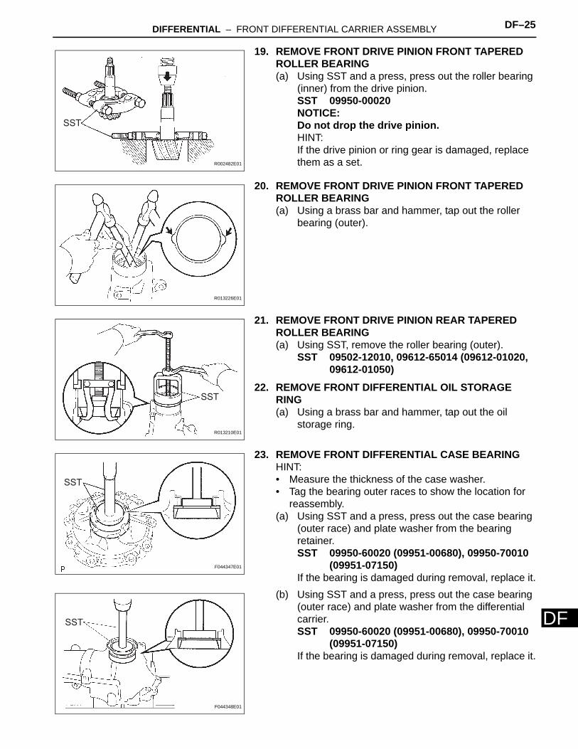
D19. REMOVE FRONT DRIVE PINION FRONT TAPERED ROLLER BEARING(a) Using SST and a press, press out the roller bearing
(inner) from the drive pinion.SST 09950-00020NOTICE:Do not drop the drive pinion.HINT:If the drive pinion or ring gear is damaged, replace them as a set.
20. REMOVE FRONT DRIVE PINION FRONT TAPERED ROLLER BEARING(a) Using a brass bar and hammer, tap out the roller
bearing (outer).
21. REMOVE FRONT DRIVE PINION REAR TAPERED ROLLER BEARING(a) Using SST, remove the roller bearing (outer).
SST 09502-12010, 09612-65014 (09612-01020, 09612-01050)
22. REMOVE FRONT DIFFERENTIAL OIL STORAGE RING(a) Using a brass bar and hammer, tap out the oil
storage ring.
23. REMOVE FRONT DIFFERENTIAL CASE BEARINGHINT:• Measure the thickness of the case washer.• Tag the bearing outer races to show the location for
reassembly.(a) Using SST and a press, press out the case bearing
(outer race) and plate washer from the bearing retainer.SST 09950-60020 (09951-00680), 09950-70010
(09951-07150)If the bearing is damaged during removal, replace it.
(b) Using SST and a press, press out the case bearing (outer race) and plate washer from the differential carrier.SST 09950-60020 (09951-00680), 09950-70010
(09951-07150)If the bearing is damaged during removal, replace it.
SST
R002482E01
R013226E01
SST
R013210E01
SST
F044347E01
SST
F044348E01
DF–26 DIFFERENTIAL – FRONT DIFFERENTIAL CARRIER ASSEMBLY
DF
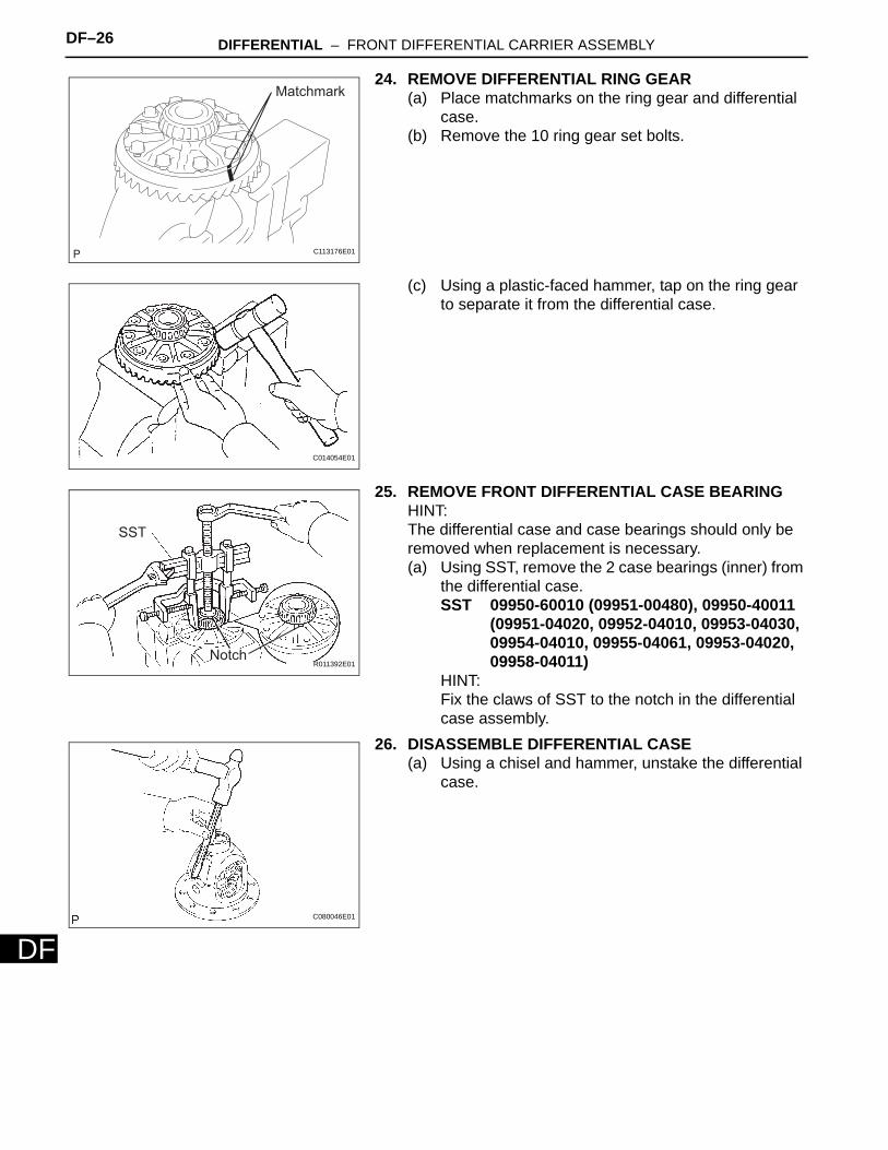
24. REMOVE DIFFERENTIAL RING GEAR(a) Place matchmarks on the ring gear and differential
case.(b) Remove the 10 ring gear set bolts.
(c) Using a plastic-faced hammer, tap on the ring gear to separate it from the differential case.
25. REMOVE FRONT DIFFERENTIAL CASE BEARINGHINT:The differential case and case bearings should only be removed when replacement is necessary.(a) Using SST, remove the 2 case bearings (inner) from
the differential case.SST 09950-60010 (09951-00480), 09950-40011
(09951-04020, 09952-04010, 09953-04030, 09954-04010, 09955-04061, 09953-04020, 09958-04011)
HINT:Fix the claws of SST to the notch in the differential case assembly.
26. DISASSEMBLE DIFFERENTIAL CASE(a) Using a chisel and hammer, unstake the differential
case.
Matchmark
C113176E01
C014054E01
SST
NotchR011392E01
C080046E01

DIFFERENTIAL – FRONT DIFFERENTIAL CARRIER ASSEMBLY DF–27
F
D(b) Using a pin punch and hammer, tap out the straight pin.
(c) Remove the following parts from the differential case.
(1) Differential pinion gear (2 pieces)(2) Differential pinion gear thrust washer (2 pieces)(3) Differential pinion shaft(4) Differential side gear (2 pieces)(5) Differential side gear thrust washer (2 pieces)
27. INSPECT DIFFERENTIAL GEAR KIT(a) Check that the differential pinion and differential
side gear are not damaged.If the differential pinion or differential side gear is damaged, replace the differential gear kit.
28. INSPECT FRONT DIFFERENTIAL CASE(a) Check that the differential case is not damaged.
If the differential case is damaged, replace it.29. REMOVE FRONT DIFFERENTIAL SIDE GEAR
NEEDLE ROLLER BEARING(a) Using a brass bar and hammer, tap out the 2
bearings.
G020264E01
B084283E01
(1)
(1)
(2)
(3)
(2)
(4)
(4)
(5)
(5)
F044349E01
SA00353E01
DF–28 DIFFERENTIAL – FRONT DIFFERENTIAL CARRIER ASSEMBLY
DF
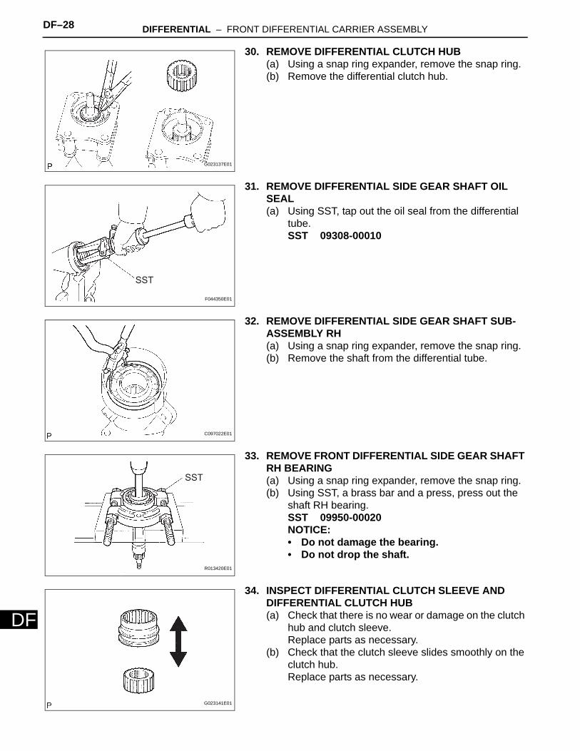
30. REMOVE DIFFERENTIAL CLUTCH HUB(a) Using a snap ring expander, remove the snap ring.(b) Remove the differential clutch hub.
31. REMOVE DIFFERENTIAL SIDE GEAR SHAFT OIL SEAL(a) Using SST, tap out the oil seal from the differential
tube.SST 09308-00010
32. REMOVE DIFFERENTIAL SIDE GEAR SHAFT SUB-ASSEMBLY RH(a) Using a snap ring expander, remove the snap ring.(b) Remove the shaft from the differential tube.
33. REMOVE FRONT DIFFERENTIAL SIDE GEAR SHAFT RH BEARING(a) Using a snap ring expander, remove the snap ring.(b) Using SST, a brass bar and a press, press out the
shaft RH bearing.SST 09950-00020NOTICE:• Do not damage the bearing.• Do not drop the shaft.
34. INSPECT DIFFERENTIAL CLUTCH SLEEVE AND DIFFERENTIAL CLUTCH HUB(a) Check that there is no wear or damage on the clutch
hub and clutch sleeve.Replace parts as necessary.
(b) Check that the clutch sleeve slides smoothly on the clutch hub.Replace parts as necessary.
G023137E01
SST
F044350E01
C097022E01
SST
R013420E01
G023141E01
DIFFERENTIAL – FRONT DIFFERENTIAL CARRIER ASSEMBLY DF–29
F
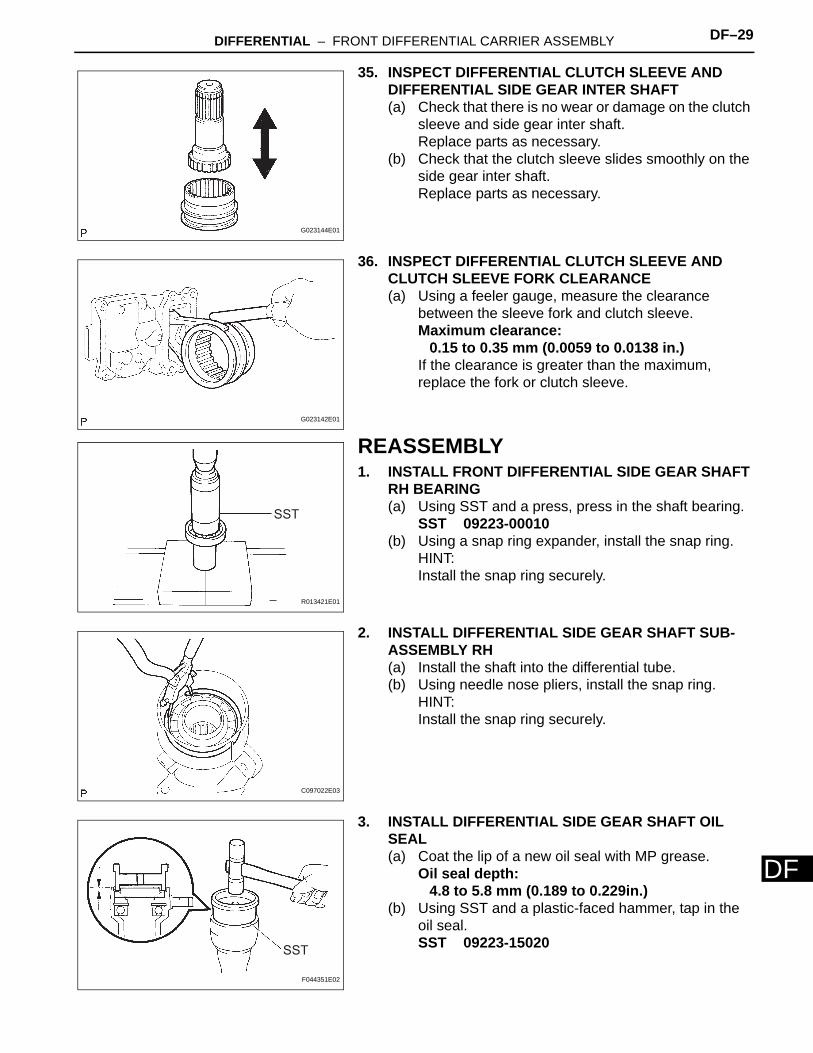
D35. INSPECT DIFFERENTIAL CLUTCH SLEEVE AND DIFFERENTIAL SIDE GEAR INTER SHAFT(a) Check that there is no wear or damage on the clutch
sleeve and side gear inter shaft.Replace parts as necessary.
(b) Check that the clutch sleeve slides smoothly on the side gear inter shaft.Replace parts as necessary.
36. INSPECT DIFFERENTIAL CLUTCH SLEEVE AND CLUTCH SLEEVE FORK CLEARANCE(a) Using a feeler gauge, measure the clearance
between the sleeve fork and clutch sleeve.Maximum clearance:
0.15 to 0.35 mm (0.0059 to 0.0138 in.)If the clearance is greater than the maximum, replace the fork or clutch sleeve.
REASSEMBLY1. INSTALL FRONT DIFFERENTIAL SIDE GEAR SHAFT
RH BEARING(a) Using SST and a press, press in the shaft bearing.
SST 09223-00010(b) Using a snap ring expander, install the snap ring.
HINT:Install the snap ring securely.
2. INSTALL DIFFERENTIAL SIDE GEAR SHAFT SUB-ASSEMBLY RH(a) Install the shaft into the differential tube.(b) Using needle nose pliers, install the snap ring.
HINT:Install the snap ring securely.
3. INSTALL DIFFERENTIAL SIDE GEAR SHAFT OIL SEAL(a) Coat the lip of a new oil seal with MP grease.
Oil seal depth:4.8 to 5.8 mm (0.189 to 0.229in.)
(b) Using SST and a plastic-faced hammer, tap in the oil seal.SST 09223-15020
G023144E01
G023142E01
SST
R013421E01
C097022E03
SST
F044351E02
DF–30 DIFFERENTIAL – FRONT DIFFERENTIAL CARRIER ASSEMBLY
DF
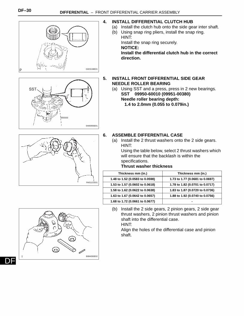
4. INSTALL DIFFERENTIAL CLUTCH HUB(a) Install the clutch hub onto the side gear inter shaft.(b) Using snap ring pliers, install the snap ring.
HINT:Install the snap ring securely.NOTICE:Install the differential clutch hub in the correct direction.
5. INSTALL FRONT DIFFERENTIAL SIDE GEAR NEEDLE ROLLER BEARING(a) Using SST and a press, press in 2 new bearings.
SST 09950-60010 (09951-00380)Needle roller bearing depth:
1.4 to 2.0mm (0.055 to 0.079in.)
6. ASSEMBLE DIFFERENTIAL CASE(a) Install the 2 thrust washers onto the 2 side gears.
HINT:Using the table below, select 2 thrust washers which will ensure that the backlash is within the specifications.Thrust washer thickness
(b) Install the 2 side gears, 2 pinion gears, 2 side gear thrust washers, 2 pinion thrust washers and pinion shaft into the differential case.HINT:Align the holes of the differential case and pinion shaft.
G023138E01
SST
SA00355E01
FA01121E01
Thickness mm (in.) Thickness mm (in.)
1.48 to 1.52 (0.0583 to 0.0598) 1.73 to 1.77 (0.0681 to 0.0697)
1.53 to 1.57 (0.0602 to 0.0618) 1.78 to 1.82 (0.0701 to 0.0717)
1.58 to 1.62 (0.0622 to 0.0638) 1.83 to 1.87 (0.0720 to 0.0736)
1.63 to 1.67 (0.0642 to 0.0657) 1.88 to 1.92 (0.0740 to 0.0756)
1.68 to 1.72 (0.0661 to 0.0677) -
B084283E02
DIFFERENTIAL – FRONT DIFFERENTIAL CARRIER ASSEMBLY DF–31
F
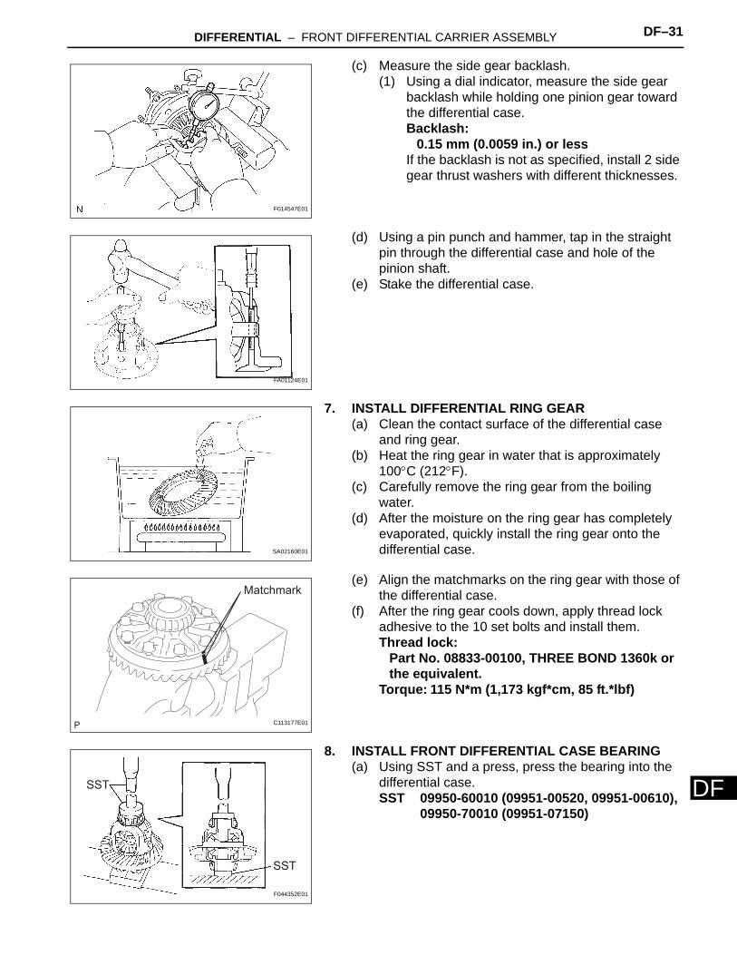
D(c) Measure the side gear backlash.(1) Using a dial indicator, measure the side gear
backlash while holding one pinion gear toward the differential case.Backlash:
0.15 mm (0.0059 in.) or lessIf the backlash is not as specified, install 2 side gear thrust washers with different thicknesses.
(d) Using a pin punch and hammer, tap in the straight pin through the differential case and hole of the pinion shaft.
(e) Stake the differential case.
7. INSTALL DIFFERENTIAL RING GEAR(a) Clean the contact surface of the differential case
and ring gear.(b) Heat the ring gear in water that is approximately
100°C (212°F).(c) Carefully remove the ring gear from the boiling
water.(d) After the moisture on the ring gear has completely
evaporated, quickly install the ring gear onto the differential case.
(e) Align the matchmarks on the ring gear with those of the differential case.
(f) After the ring gear cools down, apply thread lock adhesive to the 10 set bolts and install them.Thread lock:
Part No. 08833-00100, THREE BOND 1360k or the equivalent.
Torque: 115 N*m (1,173 kgf*cm, 85 ft.*lbf)
8. INSTALL FRONT DIFFERENTIAL CASE BEARING(a) Using SST and a press, press the bearing into the
differential case.SST 09950-60010 (09951-00520, 09951-00610),
09950-70010 (09951-07150)
F014547E01
FA01124E01
SA02160E01
Matchmark
C113177E01
SST
SST
F044352E01
DF–32 DIFFERENTIAL – FRONT DIFFERENTIAL CARRIER ASSEMBLY
DF
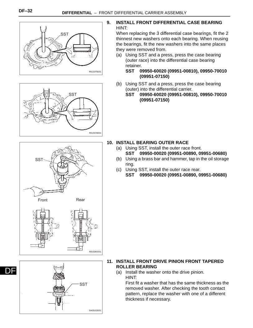
9. INSTALL FRONT DIFFERENTIAL CASE BEARINGHINT:When replacing the 3 differential case bearings, fit the 2 thinnest new washers onto each bearing. When reusing the bearings, fit the new washers into the same places they were removed from.(a) Using SST and a press, press the case bearing
(outer race) into the differential case bearing retainer.SST 09950-60020 (09951-00810), 09950-70010
(09951-07150)(b) Using SST and a press, press the case bearing
(outer) into the differential carrier.SST 09950-60020 (09951-00810), 09950-70010
(09951-07150)
10. INSTALL BEARING OUTER RACE(a) Using SST, install the outer race front.
SST 09950-00020 (09951-00890, 09951-00680)(b) Using a brass bar and hammer, tap in the oil storage
ring.(c) Using SST, install the outer race rear.
SST 09950-00020 (09951-00890, 09951-00680)
11. INSTALL FRONT DRIVE PINION FRONT TAPERED ROLLER BEARING(a) Install the washer onto the drive pinion.
HINT:First fit a washer that has the same thickness as the removed washer. After checking the tooth contact pattern, replace the washer with one of a different thickness if necessary.
SST
R013375E01
SST
R013376E01
Front Rear
SST
R013281E01
SST
SA03102E01
DIFFERENTIAL – FRONT DIFFERENTIAL CARRIER ASSEMBLY DF–33
F
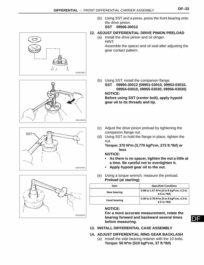
D(b) Using SST and a press, press the front bearing onto the drive pinion.SST 09506-30012
12. ADJUST DIFFERENTIAL DRIVE PINION PRELOAD(a) Install the drive pinion and oil slinger.
HINT:Assemble the spacer and oil seal after adjusting the gear contact pattern.
(b) Using SST, install the companion flange.SST 09950-30012 (09951-03010, 09953-03010,
09954-03010, 09955-03030, 09956-03020)NOTICE:Before using SST (center bolt), apply hypoid gear oil to its threads and tip.
(c) Adjust the drive pinion preload by tightening the companion flange nut.
(d) Using SST to hold the flange in place, tighten the nut.Torque: 370 N*m (3,770 kgf*cm, 273 ft.*lbf) or
lessNOTICE:• As there is no spacer, tighten the nut a little at
a time. Be careful not to overtighten it.• Apply hypoid gear oil to the nut.
(e) Using a torque wrench, measure the preload.Preload (at starting)
NOTICE:For a more accurate measurement, rotate the bearing forward and backward several times before measuring.
13. INSTALL DIFFERENTIAL CASE ASSEMBLY14. ADJUST DIFFERENTIAL RING GEAR BACKLASH
(a) Install the side bearing retainer with the 10 bolts.Torque: 50 N*m (510 kgf*cm, 37 ft.*lbf)
C028218E01
R011163E03
SST
SA02347E01
SA02352E01
Item Specified Condition
New bearing 0.98 to 1.57 N*m (5 to 8 kgf*cm, 4.3 to 6.9 in.*lbf)
Used bearing 0.49 to 0.78 N*m (5 to 8 kgf*cm, 4.3 to 6.9 in.*lbf)
DF–34 DIFFERENTIAL – FRONT DIFFERENTIAL CARRIER ASSEMBLY
DF
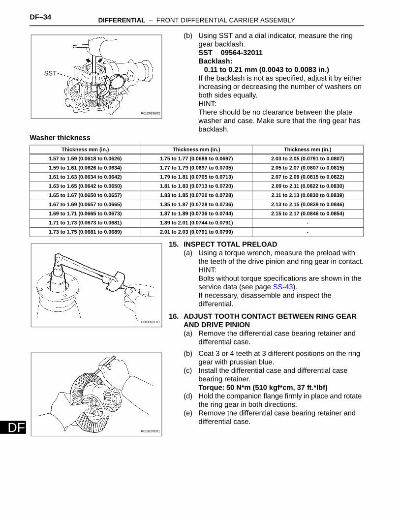
(b) Using SST and a dial indicator, measure the ring gear backlash.SST 09564-32011Backlash:
0.11 to 0.21 mm (0.0043 to 0.0083 in.)If the backlash is not as specified, adjust it by either increasing or decreasing the number of washers on both sides equally.HINT:There should be no clearance between the plate washer and case. Make sure that the ring gear has backlash.
Washer thickness
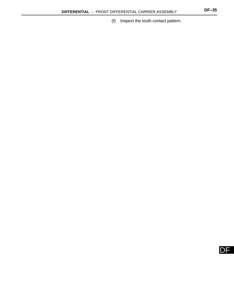
15. INSPECT TOTAL PRELOAD(a) Using a torque wrench, measure the preload with
the teeth of the drive pinion and ring gear in contact.HINT:Bolts without torque specifications are shown in the service data (see page SS-43).If necessary, disassemble and inspect the differential.
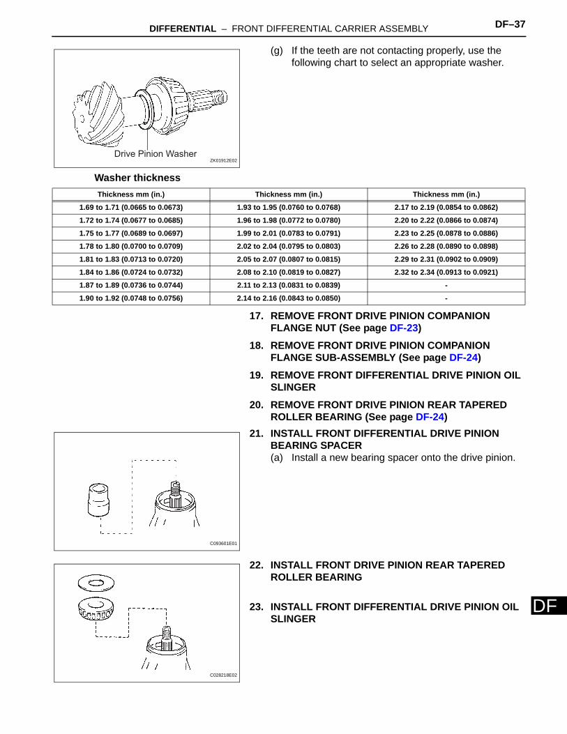
16. ADJUST TOOTH CONTACT BETWEEN RING GEAR AND DRIVE PINION(a) Remove the differential case bearing retainer and
differential case.(b) Coat 3 or 4 teeth at 3 different positions on the ring
gear with prussian blue.(c) Install the differential case and differential case
bearing retainer.Torque: 50 N*m (510 kgf*cm, 37 ft.*lbf)
(d) Hold the companion flange firmly in place and rotate the ring gear in both directions.
(e) Remove the differential case bearing retainer and differential case.
SST
R012683E02
Thickness mm (in.) Thickness mm (in.) Thickness mm (in.)
1.57 to 1.59 (0.0618 to 0.0626) 1.75 to 1.77 (0.0689 to 0.0697) 2.03 to 2.05 (0.0791 to 0.0807)
1.59 to 1.61 (0.0626 to 0.0634) 1.77 to 1.79 (0.0697 to 0.0705) 2.05 to 2.07 (0.0807 to 0.0815)
1.61 to 1.63 (0.0634 to 0.0642) 1.79 to 1.81 (0.0705 to 0.0713) 2.07 to 2.09 (0.0815 to 0.0822)
1.63 to 1.65 (0.0642 to 0.0650) 1.81 to 1.83 (0.0713 to 0.0720) 2.09 to 2.11 (0.0822 to 0.0830)
1.65 to 1.67 (0.0650 to 0.0657) 1.83 to 1.85 (0.0720 to 0.0728) 2.11 to 2.13 (0.0830 to 0.0839)
1.67 to 1.69 (0.0657 to 0.0665) 1.85 to 1.87 (0.0728 to 0.0736) 2.13 to 2.15 (0.0839 to 0.0846)
1.69 to 1.71 (0.0665 to 0.0673) 1.87 to 1.89 (0.0736 to 0.0744) 2.15 to 2.17 (0.0846 to 0.0854)
1.71 to 1.73 (0.0673 to 0.0681) 1.89 to 2.01 (0.0744 to 0.0791) -
1.73 to 1.75 (0.0681 to 0.0689) 2.01 to 2.03 (0.0791 to 0.0799) -
C003092E01
R013220E01
DIFFERENTIAL – FRONT DIFFERENTIAL CARRIER ASSEMBLY DF–35
F
D(f) Inspect the tooth contact pattern.

DF–36 DIFFERENTIAL – FRONT DIFFERENTIAL CARRIER ASSEMBLY
DF
Proper Contact
Drive Side Toe Contact Face Contact
Select an adjusting washer that will shift the
drive pinion closer to the ring gear.
Heel Contact Flank Contact
Select an adjusting washer that will shift the
drive pinion away from the ring gear.
Toe Contact Face Contact
Select an adjusting washer that will shift the
drive pinion closer to the ring gear.
Heel Contact Flank Contact
Select an adjusting washer that will shift the
drive pinion away from the ring gear.
Coast Side
C113178E02
DIFFERENTIAL – FRONT DIFFERENTIAL CARRIER ASSEMBLY DF–37
F
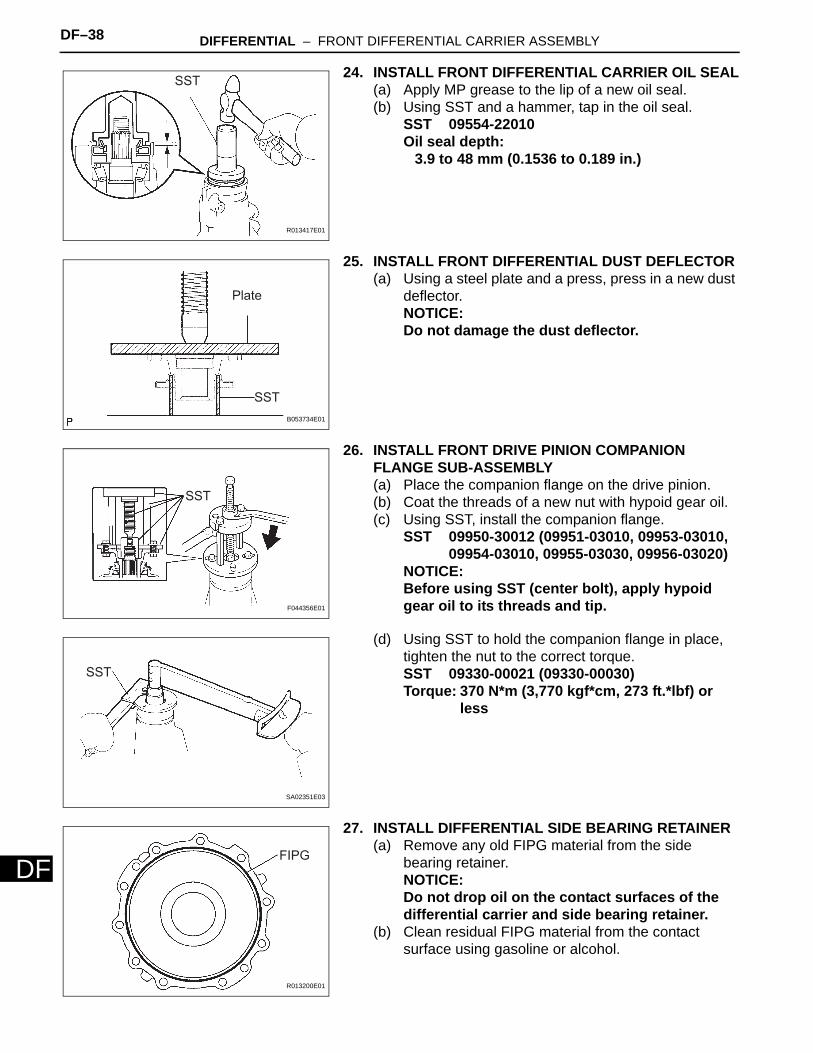
D(g) If the teeth are not contacting properly, use the following chart to select an appropriate washer.
Washer thickness
17. REMOVE FRONT DRIVE PINION COMPANION FLANGE NUT (See page DF-23)
18. REMOVE FRONT DRIVE PINION COMPANION FLANGE SUB-ASSEMBLY (See page DF-24)
19. REMOVE FRONT DIFFERENTIAL DRIVE PINION OIL SLINGER
20. REMOVE FRONT DRIVE PINION REAR TAPERED ROLLER BEARING (See page DF-24)
21. INSTALL FRONT DIFFERENTIAL DRIVE PINION BEARING SPACER(a) Install a new bearing spacer onto the drive pinion.
22. INSTALL FRONT DRIVE PINION REAR TAPERED ROLLER BEARING
23. INSTALL FRONT DIFFERENTIAL DRIVE PINION OIL SLINGER
Drive Pinion WasherZK01912E02
Thickness mm (in.) Thickness mm (in.) Thickness mm (in.)
1.69 to 1.71 (0.0665 to 0.0673) 1.93 to 1.95 (0.0760 to 0.0768) 2.17 to 2.19 (0.0854 to 0.0862)
1.72 to 1.74 (0.0677 to 0.0685) 1.96 to 1.98 (0.0772 to 0.0780) 2.20 to 2.22 (0.0866 to 0.0874)
1.75 to 1.77 (0.0689 to 0.0697) 1.99 to 2.01 (0.0783 to 0.0791) 2.23 to 2.25 (0.0878 to 0.0886)
1.78 to 1.80 (0.0700 to 0.0709) 2.02 to 2.04 (0.0795 to 0.0803) 2.26 to 2.28 (0.0890 to 0.0898)
1.81 to 1.83 (0.0713 to 0.0720) 2.05 to 2.07 (0.0807 to 0.0815) 2.29 to 2.31 (0.0902 to 0.0909)
1.84 to 1.86 (0.0724 to 0.0732) 2.08 to 2.10 (0.0819 to 0.0827) 2.32 to 2.34 (0.0913 to 0.0921)
1.87 to 1.89 (0.0736 to 0.0744) 2.11 to 2.13 (0.0831 to 0.0839) -
1.90 to 1.92 (0.0748 to 0.0756) 2.14 to 2.16 (0.0843 to 0.0850) -
C093601E01
C028218E02
DF–38 DIFFERENTIAL – FRONT DIFFERENTIAL CARRIER ASSEMBLY
DF
24. INSTALL FRONT DIFFERENTIAL CARRIER OIL SEAL(a) Apply MP grease to the lip of a new oil seal.(b) Using SST and a hammer, tap in the oil seal.
SST 09554-22010Oil seal depth:
3.9 to 48 mm (0.1536 to 0.189 in.)
25. INSTALL FRONT DIFFERENTIAL DUST DEFLECTOR(a) Using a steel plate and a press, press in a new dust
deflector.NOTICE:Do not damage the dust deflector.
26. INSTALL FRONT DRIVE PINION COMPANION FLANGE SUB-ASSEMBLY(a) Place the companion flange on the drive pinion.(b) Coat the threads of a new nut with hypoid gear oil.(c) Using SST, install the companion flange.
SST 09950-30012 (09951-03010, 09953-03010, 09954-03010, 09955-03030, 09956-03020)
NOTICE:Before using SST (center bolt), apply hypoid gear oil to its threads and tip.
(d) Using SST to hold the companion flange in place, tighten the nut to the correct torque.SST 09330-00021 (09330-00030)Torque: 370 N*m (3,770 kgf*cm, 273 ft.*lbf) or
less
27. INSTALL DIFFERENTIAL SIDE BEARING RETAINER(a) Remove any old FIPG material from the side
bearing retainer.NOTICE:Do not drop oil on the contact surfaces of the differential carrier and side bearing retainer.
(b) Clean residual FIPG material from the contact surface using gasoline or alcohol.
SST
R013417E01
SST
Plate
B053734E01
SST
F044356E01
SST
SA02351E03
FIPG
R013200E01
DIFFERENTIAL – FRONT DIFFERENTIAL CARRIER ASSEMBLY DF–39
F
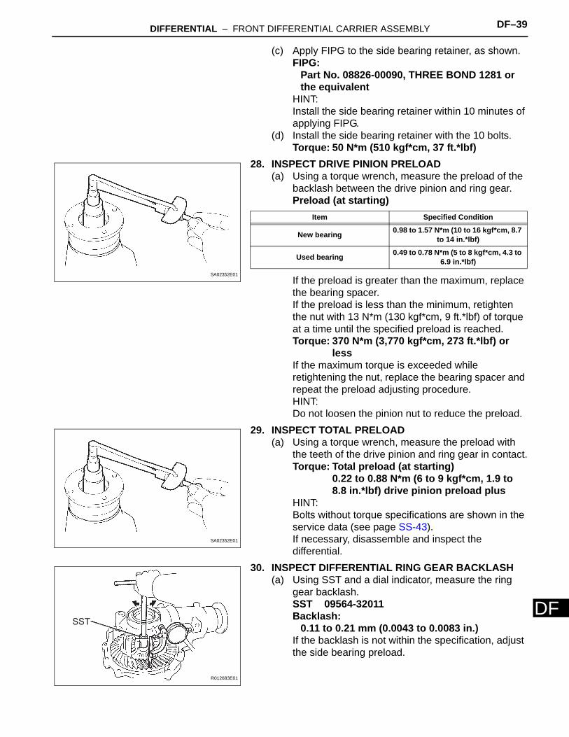
D(c) Apply FIPG to the side bearing retainer, as shown.FIPG:
Part No. 08826-00090, THREE BOND 1281 or the equivalent
HINT:Install the side bearing retainer within 10 minutes of applying FIPG.
(d) Install the side bearing retainer with the 10 bolts.Torque: 50 N*m (510 kgf*cm, 37 ft.*lbf)
28. INSPECT DRIVE PINION PRELOAD(a) Using a torque wrench, measure the preload of the
backlash between the drive pinion and ring gear.Preload (at starting)
If the preload is greater than the maximum, replace the bearing spacer.If the preload is less than the minimum, retighten the nut with 13 N*m (130 kgf*cm, 9 ft.*lbf) of torque at a time until the specified preload is reached.Torque: 370 N*m (3,770 kgf*cm, 273 ft.*lbf) or
lessIf the maximum torque is exceeded while retightening the nut, replace the bearing spacer and repeat the preload adjusting procedure.HINT:Do not loosen the pinion nut to reduce the preload.
29. INSPECT TOTAL PRELOAD(a) Using a torque wrench, measure the preload with
the teeth of the drive pinion and ring gear in contact.Torque: Total preload (at starting)
0.22 to 0.88 N*m (6 to 9 kgf*cm, 1.9 to 8.8 in.*lbf) drive pinion preload plus
HINT:Bolts without torque specifications are shown in the service data (see page SS-43).If necessary, disassemble and inspect the differential.
30. INSPECT DIFFERENTIAL RING GEAR BACKLASH(a) Using SST and a dial indicator, measure the ring
gear backlash.SST 09564-32011Backlash:
0.11 to 0.21 mm (0.0043 to 0.0083 in.)If the backlash is not within the specification, adjust the side bearing preload.
SA02352E01
Item Specified Condition
New bearing 0.98 to 1.57 N*m (10 to 16 kgf*cm, 8.7 to 14 in.*lbf)
Used bearing 0.49 to 0.78 N*m (5 to 8 kgf*cm, 4.3 to 6.9 in.*lbf)
SA02352E01
SST
R012683E01
DF–40 DIFFERENTIAL – FRONT DIFFERENTIAL CARRIER ASSEMBLY
DF
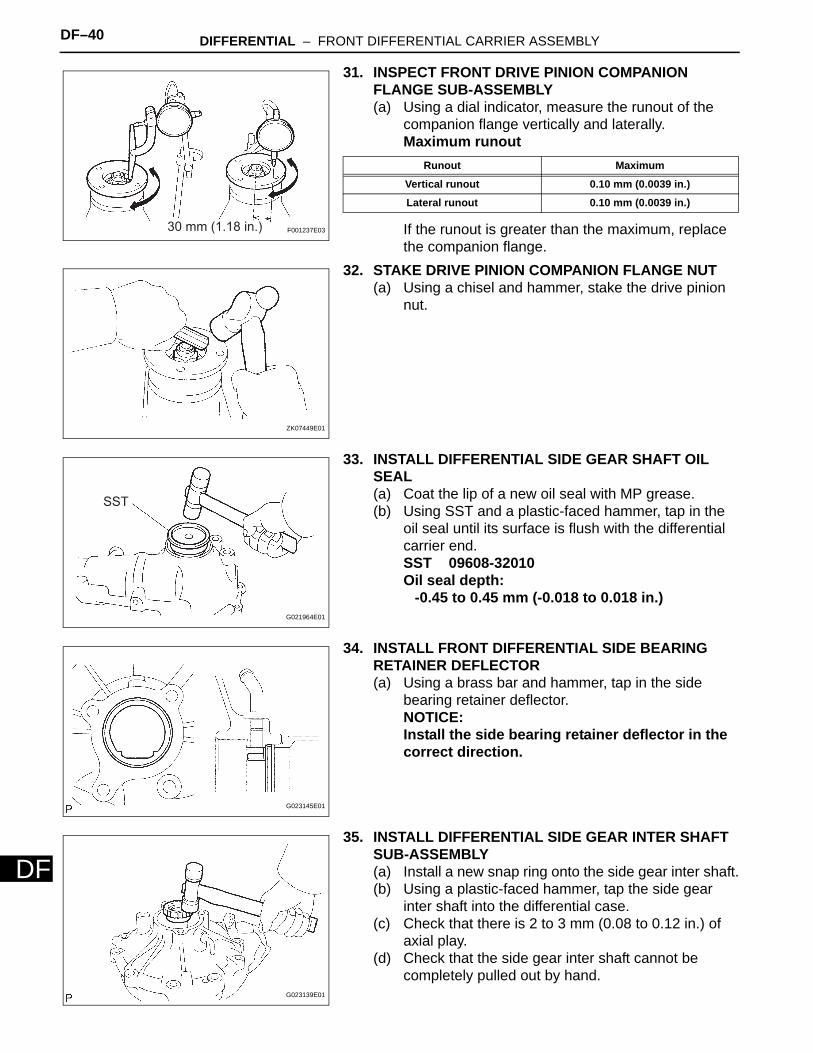
31. INSPECT FRONT DRIVE PINION COMPANION FLANGE SUB-ASSEMBLY(a) Using a dial indicator, measure the runout of the
companion flange vertically and laterally.Maximum runout
If the runout is greater than the maximum, replace the companion flange.
32. STAKE DRIVE PINION COMPANION FLANGE NUT(a) Using a chisel and hammer, stake the drive pinion
nut.
33. INSTALL DIFFERENTIAL SIDE GEAR SHAFT OIL SEAL(a) Coat the lip of a new oil seal with MP grease.(b) Using SST and a plastic-faced hammer, tap in the
oil seal until its surface is flush with the differential carrier end.SST 09608-32010Oil seal depth:
-0.45 to 0.45 mm (-0.018 to 0.018 in.)
34. INSTALL FRONT DIFFERENTIAL SIDE BEARING RETAINER DEFLECTOR(a) Using a brass bar and hammer, tap in the side
bearing retainer deflector.NOTICE:Install the side bearing retainer deflector in the correct direction.
35. INSTALL DIFFERENTIAL SIDE GEAR INTER SHAFT SUB-ASSEMBLY(a) Install a new snap ring onto the side gear inter shaft.(b) Using a plastic-faced hammer, tap the side gear
inter shaft into the differential case.(c) Check that there is 2 to 3 mm (0.08 to 0.12 in.) of
axial play.(d) Check that the side gear inter shaft cannot be
completely pulled out by hand.
30 mm (1.18 in.) F001237E03
Runout Maximum
Vertical runout 0.10 mm (0.0039 in.)
Lateral runout 0.10 mm (0.0039 in.)
ZK07449E01
SST
G021964E01
G023145E01
G023139E01
DIFFERENTIAL – FRONT DIFFERENTIAL CARRIER ASSEMBLY DF–41
F
D36. INSTALL FRONT DIFFERENTIAL TUBE ASSEMBLY(a) Remove any old FIPG material from the contact
surfaces of the differential and clutch case.NOTICE:Do not drop oil on the contact surfaces of the differential and clutch case.
(b) Clean residual FIPG material from the contact surface using gasoline or alcohol.
(c) Apply FIPG to the differential as shown.FIPG:
Part No. 08826-00090, THREE BOND 1281 or the equivalent
HINT:Install the differential tube within 10 minutes of applying FIPG.
(d) Install the differential tube onto the differential.(e) Clean the threads of the 4 bolts and retainer bolt
holes with toluene or trichloroethylene.(f) Apply adhesive to 2 or 3 threads of each bolt end.
Adhesive:Part No. 08833-00070, THREE BOND 1281 or the equivalent
(g) Install the 4 bolts.Torque: 110 N*m (1,120 kgf*cm, 81 ft.*lbf)
37. INSTALL DIFFERENTIAL VACUUM ACTUATOR ASSEMBLY(a) Remove any FIPG material from the contact surface
of the differential and clutch case. Also, do not drop oil on the contact surfaces.
(b) Clean residual FIPG material from the contact surfaces using gasoline or alcohol.
(c) Apply FIPG to the differential tube as shown.FIPG:
Part No. 08826-00090, THREE BOND 1281 or the equivalent
HINT:Install the actuator within 10 minutes of applying FIPG.
(d) Clean the threads of the 4 bolts and retainer bolt holes with toluene or trichloroethylene.
(e) Install the actuator onto the differential tube.(f) Apply adhesive to 2 or 3 threads of each bolt end.
Adhesive:Part No. 08833-00070, THREE BOND 1281 or the equivalent
(g) Install the 4 bolts.Torque: 21 N*m (210 kgf*cm, 15 ft.*lbf)
FIPG
F044357E01
G023134E01
G023140E01
G023143E01
![Untitled-1 [] assembly.pdf · 2015-11-13 · ring gear with red lead. Hold the companion flange firmly and rotate the ... Rear Differential (Differential Carrier) SA-23 FA20t3 Face](https://img.pdfslide.net/doc/110x75/5e75861216f97313e478adfa/untitled-1-assemblypdf-2015-11-13-ring-gear-with-red-lead-hold-the-companion.jpg)