Embed Size (px)
Citation preview

DGAT PROGRAM KIT 37323712001INS TALLA TION INSTRUCTIONS
035-20530-001 Rev. B (0804)
Heating _ Air Conditioning
FOR MODELS:DGAM075BDD DGAT075BDD
DGAM075BDE DGAT075BDE
DGAM075BDF DGAT075BDF
DGAT070BDD DLAS075BDD
DGAT070BDE DLAS075BDE
DGAT070BDF DLAS075BDF
Use of this instruction is intended for qualified individuals experienced in the proper installation and service of manu-
factured housing heating appliances.
Fire or explosion hazard.
Failure to properly inspect and restore appliance to proper operation may cause property damage, personal injury orloss of life.
General Information
A. Before You Start
Once you have read this instruction view the video tape.
1. Thoroughly review this instruction. Contact DGAT
Program at: 1-888-665-4640 or on line at dgatpro-
[email protected], if you have any questions.
2. Inspect kit contents
a. Three (3) piece heat exchanger liner assembly
i. Part A has two (2) curved hooks and four (4)stainless steel bolts.
ii. Parts B and C have slotted holes.
b. Auxiliary limit switch assembly.
c. Customer Packet with instructions and labels
d. Card board "shoehorn" for auxiliary limit switch
assembly installation.
e. Natural gas orifice bag assembly, LP/Propane
gas orifice bag assembly, and hardware bagassembly.
f. Wire clamps
3. Gather test equipment.
a. Digital Thermometer
b. 5/16" Hex head driver
c. Flashlight or droplight
d. Inspection mirror
e. Phillipshead screwdriver
f. Two (2) crescent wrenches
4. Tools needed to install DGAT Program Kit
a. 1/2" Wrench
b. 11/32" Nut driver
c. High temperature RTV Silicone - Source 1 PartNumber MA-HTSS-R
B. To Turn Off Gas to ApplianceThese instructions will direct you To Turn Off Gas to Appli-
ance during the inspection. A label with these instructions islocated inside the lower door. The instructions are as follows:
1. Set the thermostat to lowest setting.
2. Turn off all power to the appliance.
3. Remove control access panel.
4. Move gas control switch to "OFF" position.
C. Operating Instructions
These instructions will direct you to follow the Operating
Instructions to place the appliance in operation. A label withthe Operating Instructions is located inside the lower door.
The Operating Instructions are as follows:
1. Set the thermostat to lowest setting.
2. Turn off all electric power to the appliance.
3. This appliance is equipped with an ignition device
which automatically lights the burner. Do NOT try to
light the burner by hand.
4. Remove control access panel.
5. Move gas control switch to "OFF" position. Do notforce.
6. Wait five (5) minutes to clear out any gas. If you smell
gas, determine source and repair as necessary.
7. Move gas control to "ON" position. Do not force.
Unitary Products Group

035-20530-001Rev.B(0804)
8. Replacecontrolaccesspanel.9. Turnonallelectricalpowertotheappliance.
10.Setthermostatto thedesiredsetting.Burnerwilllight,whichmaytake30-60seconds.
11.Afterthree(3)trials,iftheappliancewillnotoperate,followthe instructionsTO TURNOFFGASTOAPPLIANCEandrefertotroubleshootingguideintheInstallationInstructionsorOwner'sManual.
D. Product Specifications
Model No. DGAT070 DGAT075
Input 70,000 Btu/hr 75,000 Btu/hr
Output 57,000 Btu/hr 61,000 Btu/hr
Air Temperature 45_75OFRise Range
Maximum Outlet165°F
Tem peratu re
Maximum External0.30" wc
Static Pressure
Part 1: Basic Information
Record the following on the DGAT Program Claim Form.
Record information clearly and legibly.
Most of this information should be available before travelling
to the job site.
A. Rating Plate Data1. Model Number
g.
2. Serial Number
Customer Data
1. Customer name, street address, city, state and zipcode.
2. Customer telephone number.
Part 2: Inspection
A. Inspect Roof Jack
1. Verify the proper Roof Jack is being used. The DGAT
is approved for use with the 4000 Series roof jack
only. See Figure 1.
B. Remove Assembly Burner
4000 SERIES 7900 SERIES
FIGURE 1: Roof Jack
NOTE:
2.
3.
The 7900 Series Roof Jack can be converted to a
4000 Series Roof Jack by replacing crown. Use pin4000-6941tC.
inspect Roof Jack. Replace if damaged, tilted,
crooked, or shows deterioration.
Remove bird screens or other obstructions to com-
bustion air inlet.
FIGURE 2: Turn power switch to off position.
1. Follow instructions TO TURN OFF GAS TO APPLI-
ANCE.
2. Disconnect wires to gas valve, igniter, and flame sen-
sor.
3. Turn off gas supply to furnace by closing manualshut-off valve. Disconnect gas supply piping.
4. Remove gas valve. See Figure 3.
2 Unitary Products Group

035-20530-001Rev.B(0804)
FIGURE 3: Gas valve removal
5. Remove the burner assembly. See Figure 4.
When burner is removed, check the ribbon porting, located in
the end of the burner to insure it is concentric and square.
Reference Figure 5. Check the seams between the burner
halves to insure that they are completely closed and tight.
The flame spreader needs to be checked for proper align-ment and to insure that it is not distorted and the burner
mounting legs should also be checked for distortion. If any of
these items are found to be out of alignment, the burner
should be replaced..
C. Inspect Heat Exchanger
1. Insert inspection mirror through burner opening. Use
flashlight or droplight to illuminate surface. Inspect
entire interior perimeter of heat exchanger. Note con-
dition per following guidelines.
a. Typical Discoloration Pattern
i. Surface must be smooth shape with no bumpsor indentations.
ii. Normal heat pattern may include light to dark
gray discoloration. See Figure 6.
iii. If visual inspection does not reveal any defor-
mation, crack, or burn through of the heat
exchanger surface, then you need to check the
entire inside surface of the heat exchanger by
feel. If you feel any roughness, deformation,
crack or burn through, proceed with replacing
the heat exchanger with 37323713001.
FIGURE 6: Typical discoloration pattern
b. Cracked. See Figure 7.
FIGURE 4: Burner assembly removal
FIGURE 7: Cracked heat exchanger
c. Deformed. See Figure 8.
FIGURE 5: Burner inspection
Unitary Products Group 3

035-20530-001Rev.B(0804)
replaced.
FIGURE 8: Deformed heat exchanger
d. Burn Through. See Figure 9.
FIGURE 9: Burned through heat exchanger
While you are feeling the inside surface, you should also
check the integrity of the rivets that secure the overflame baf-
fle to the heat exchanger drum. You can check the rivets by
pushing against each of the four (4) mounting legs. If any of
the rivets are missing, the heat exchanger will need to be
FIGURE 10: Overflame baffle located in top of heatexchanger assembly (cut-away view).
D, Corrective Actions
1. Heat Exchanger cracked, deformed or burned
through or 1 or more overflame baffle pop rivets are
missing. Replace heat exchanger with 37323713001
Replacement Heat Exchanger. Follow instructions
provided with kit.
2. If heat exchanger burn through has resulted in dam-
age to the furnace casing insulation and/or a breach
in the furnace casing, you will need to contact the
DGAT program at: 1-888-665-4640 or on line at dgat-
[email protected] to receive authorization toreplace furnace.
3. Heat Exchanger exhibits normal discoloration patternwith no defects.
a. Install DGAT Program Kit 37323712001. Followinstructions in Part 3.
Part 3: DGAT Program Kit Installation
A. Install Heat Exchanger Liner
FIGURE 11: Remove pressure switch tube.FIGURE 12: Remove burner inlet pan 12 screws asmarked and remove burner inlet pan.
4 Unitary Products Group
035-20530-001Rev.B(0804)
FIGURE 13: Remove bottom screw from air vane,loosen top screw and rotate air vane counterclockwise.Use caution when rotating air vane so that foil facedinsulation is not damaged.
FIGURE 16: Rotate liner upward to hook on overflamebaffle.
FIGURE 14" Remove burner chute mounting screws(4) and remove burner chute.
FIGURE 17: Make sure the hooks on Part A straddlethe rear right-hand leg of overflame baffle.
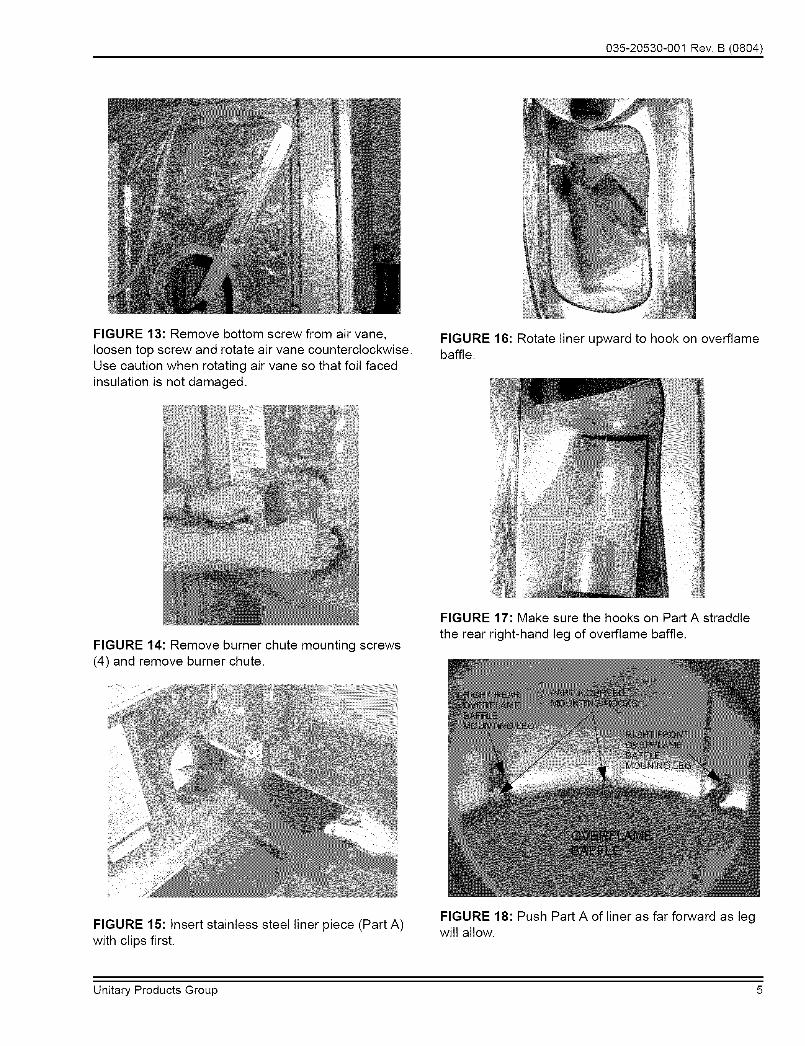
FIGURE 15: Insert stainless steel liner piece (Part A)with clips first.
FIGURE 18: Push Part A of liner as far forward as legwill allow.
Unitary Products Group 5

035-20530-001Rev.B(0804)
FIGURE 19: Insert Part B and rotate upwards.
FIGURE 20: Place Part B over stud bolts in Part A.
insert Part C and rotate upwards.
Place Part C over stud bolts in Part A.
install stainless steel nuts.
FIGURE 22: Again push assembled liner as far to frontas )ossible and tighten all (4) stainless steel nuts.
FIGURE 23: Inspect with light to make sure Part A, B,and C are pushed outward against drum.
FIGURE 21: Install stainless steel nuts found in
hardware bag. Do not tighten. FIGURE 24: Reinstall burner chute to original position.
6 Unitary Products Group

035-20530-001Rev.B(0804)
FIGURE 25: Reposition air vane to original position.Reinstall bottom screw and tighten top screw.
FIGURE 28: Reinstall burner.
FIGURE 26: Install burner inlet pan with 12 screws. Ifneeded, re-seal pan with high temperature RTVsilicone.
FIGURE 29: Reinstall gas valve and gas piping.
FIGURE 27: Remove old gas orifice, install new perchart.
FIGURE 30: Reconnect pressure tube to pressureswitch and wiring connectors to gas valve, igniter andsensor.
7 Unitary Products Group
035-20530-001Rev.B(0804)
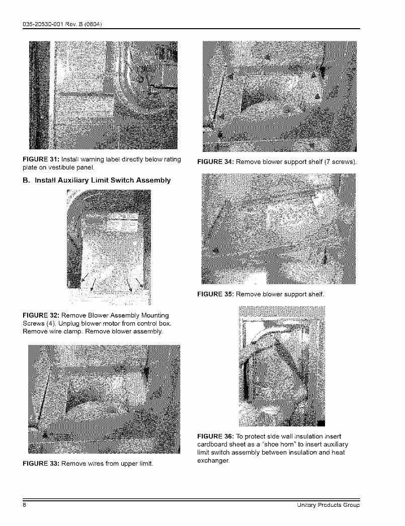
FIGURE 31: Install warning label directly below ratingplate on vestibule panel.
B. Install Auxiliary Limit Switch Assembly
FIGURE 34: Remove blower support shelf (7 screws).
FIGURE 32: Remove Blower Assembly MountingScrews (4). Unplug blower motor from control box.Remove wire clamp. Remove blower assembly.
FIGURE 35: Remove blower support shelf.
FIGURE 33: Remove wires from upper limit.
FIGURE 36: To protect side wall insulation insertcardboard sheet as a "shoe horn" to insert auxiliarylimit switch assembly between insulation and heatexchanger.
8 Unitary Products Group

035-20530-001Rev.B(0804)
FIGURE 37: Bow back plate of auxiliary limit switchassembly to insert on right-hand side of blowercompartment.
FIGURE 40: Outer plate should compress against sidecasing foil (Cut-away view).
FIGURE 38: Compress stainless loop in middle to slidepast heat exchanger. Do not skin or scrape foil frominsulation while sliding switch down side of heatexchanger.
FIGURE 41 : Push flange in until clearance holes lineup with holes in blower shelf support bracket(Cut-away view).
FIGURE 39: Remove "shoe horn".
FIGURE 42: Reinstall blower shelf. Pass wires upthrough back slot of blower shelf before locating to finalposition.
Unitary Products Group 9

035-20530-001Rev.B(0804)
FIGURE 43: Install new wire clamp in blower shelf holeon rear left-hand side of shelf. Reinstall (7) screws tosecure blower shelf.
FIGURE 46" Install new wiring diagram over existingdiagram.
FIGURE 44: Install new auxiliary limit switch leads inseries with upper limit per wiring diagram. FIGURE 47: Install danger label on vestibule panel just
below upper limit switch.
FIGURE 45" Install and secure blower on shelf. Plugblower motor into control box.
FIGURE 48: Turn gas supply back on and leak checkgas valve piping connection.
10 Unitary Products Group
035-20530-001Rev.B(0804)
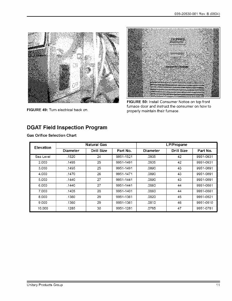
FIGURE 49: Turn electrical back on.
FIGURE 50: Install Consumer Notice on top frontfurnace door and instruct the consumer on how to
properly maintain their furnace.
DGAT Field Inspection Program
Gas Orifice Selection Chart
ElevationDiameter Part No. Diameter Part No.
Sea Level .1520 9951-1521 .0935 9951-0931
2,000 .1495 9951-1491 .0935 9951-0931
3,000 .1495 9951-1491 .0890 9951-0891
4,000 .1470 9951-1471 .0890 9951-0891
5,000 .1440 9951-1441 .0890 9951-0891
6,000 .1440 9951-1441 .0860 9951-0861
7,000 .1405 9951-1401 .0860 9951-0861
8,000 .1360 9951-1361 .0820 9951-0821
9,000 .1360 9951-1361 .0810 9951-0810
10,000 .1285 9951-1281 .0785 9951-0781
Natural Gas
Drill Size
24
25
25
26
27
27
28
29
29
30
LP/Propane
Drill Size
42
42
43
43
43
44
44
45
46
47
Unitary Products Group 11

035-20530-001Rev.B(0804)
Part 4: Checkout Data
A. Furnace Checkout
1. Verify Cardboard Pad "Shoehorn" was removed.
Remove Cardboard Pad "Shoehorn" before operat-
ing furnace.
Fire Hazard.
Failure to remove may cause property damage, per-
sonal injury or loss of fife.
2. Check Air Temperature Rise (ATR).
a. Make sure furnace has operated for at least 5minutes.
b. Measure return air temperature at top louver
openings of top furnace door.
c. Measure supply air temperature at the closet reg-
ister/grille.
d. Subtract the return air temperature from the sup-
ply air temperature to obtain the ATR.
3. If measured ATR is outside parameters shown on the
furnace rating plate, then you will need to determine
why unit is operating beyond its design parameters. Ifthe ATR is too low, it is an indication of an underfired
furnace. Make sure that your gas pressure is set
properly. If the ATR is too high, it is an indication of
an overtired furnace. Once again, you will need to
make sure that your gas pressure is set properly. If
found to be okay, you should then also clock the
meter to determine the units firing rate, and if
needed, check the supply duct system static pres-sure. Refer to Part 5 for information on how to mea-
sure gas pressure, determine the firing rate and
measure supply static pressure.
If any items tested result in findings outside the design
parameters listed on the units rating plate, it is an indication
of application/installation problems that must be addressed.
Since application/installation problems are not covered under
the warranty, you will need to discuss this situation with the
homeowner as they will be responsible for covering any
charges to correct any problems found.
4. If measured ATR is within design parameters, pro-
ceed to step B and complete your on-site visit.
B. Complete On-Site Visit
1. Verify all gas-fueled appliances are returned to nor-
mal operation. Follow instructions provided by the
appliance manufacturer.
2. Complete the DGAT Program Claim Form.
a. Record your name and company information.
b. Obtain homeowner's signature.
c. Sign claim form to certify the furnace has been
properly upgraded.
3. Review the Consumer Notice with the customer.
12 Unitary Products Group

035-20530-001Rev.B(0804)
Part 5: Additional Testing Procedures
A. Measure Gas Pressure 3. Allow burner to operate 5 minutes.
a. Remove gas valve OUT PRESS TAP plug using 4. Measure time required (in seconds) for gas meter 23/16" Alien wrench. Install 1/8 NPT hose barb fit- cubic foot dial to rotate one complete turn (or 1/2
ting. See Figure 51. cubic foot dial to rotate 4 complete turns).
5. Calculate input:
FIGURE 51 : Pressure tap
B,
b. Connect manometer positive (+) pressure hose
fitting to OUT PRESS TAP hose barb fitting.
c. Follow OPERATING INSTRUCTIONS to place
furnace in operation.
d. Allow burner to operate 30-60 seconds. Measure
Outlet (Manifold) Gas Pressure. Adjust pressure
to 3.5" + 0.2 w.c. for natural gas, or 10.0" _+0.2
w.c. for LPipropane.
e. Follow instructions TO TURN OFF GAS TO
APPLIANCE.
f. Remove hose barb from gas valve. Install plug.
4. Follow OPERATING INSTRUCTIONS to place fur-
nace in operation.
5. Operate furnace through at least one (1) complete
heating cycle to confirm proper operation.
Measure Input Rate
1. Adjust controls on all other gas-fired appliances to
prevent operation. Extinguish pilot(s), if applicable.
Follow instructions provided by the appliance manu-facturer.
2. Follow OPERATING INSTRUCTIONS to place fur-
nace in operation.
[Gas Heating Value] 2 x 7200Input
Time
2. Assume 1030 BTU per cubic foot for natural gas if gas
supplier cannot provide exact value.
C. Measure Static Pressure
1. Verify upper door is installed and furnace burner andblower are operating in heating speed.
2. Supply Static Pressure.
a. Remove top screws from coil cabinet cover plates
(3 total).
b. Connect manometer positive (+) pressure hose
fitting to Static Pressure Probe.
c. Insert static pressure probe into each screw hole.Insert probe straight into hole 6". Probe must be
level (horizontal) for proper measurement. See
Figure 52.
FIGURE 52: Measuring supply static pressure
Part 6: Submit Claim
A. Mail Documentation
1. Submit original DGAT Program Claim to:
York InternationalAttn: Warranty Dept.P.O. Box 385Norman, OK 73070
Unitary Products Group 13

035-20530-001Rev.B(0804)
NOTES
14 Unitary Products Group

035-20530-001Rev.B(0804)
NOTES
Unitary Products Group 15

NOTES
Subject to change without notice. Printed in U.S.A.Copyright t7 by York International Corp. 2004. All rights reserved.
UnitaryProductsGroup
RO.Box19014
035-20530-001 Rev. B (0804)Supersedes: 035-20530-001 Rev. A (0804)
WichitaKS
67204-901