Embed Size (px)
Citation preview

DHANALAKSHMI COLLEGE OF ENGINEERING (Dr.VPR Nagar, Manimangalam, Tambaram)
Chennai - 601 301
DEPARTMENT OF MECHANICAL ENGINEERING III YEAR MECHANICAL - V SEMESTER
GE6503 – DESIGN OF MACHINE ELEMENTS
UNIT – 2 (STUDY NOTES) Prepared by: R. SENDIL KUMAR, AP/MECH P.V. ELUMALAI, AP/MECH P. SIVA KUMAR, AP/MECH
ACADEMIC YEAR (2017 - 2018) - ODD SEMESTER

Prepared by R. SENDIL KUMAR, P.V. ELUMALAI, P. SIVA KUMAR, AP/MECH Page 2
UNIT 2 : SHAFTS AND COUPLING
PART - A
1. List the various failures occurred in sunk keys? (A/M - 08)
Shear failure and Crushing failure.
2. Why is maximum shear stress theory used for shaft? (A/M - 09) (N/D - 09)
Since the shaft is made of ductile materials, maximum shear stress theory is used.
3. What is coupling? (A/M -09) (N/D - 09)
Couplings are used to connect sections of long transmission shafts and to connect the
shaft of a driving machine to the shaft of a driven machine.
4. Under what circumstances flexible couplings are used? (N/D - 07/08/09)
They are used to join the abutting ends of the shafts when they are not in exact alignment. They are used to permit an axial misalignment of the shafts without under absorption of
power, which the shafts are transmitting.
5. Differentiate between keys and splines. (N/D - 11)
Keys – A shaft which is having single keyway Keys are used in couplings. Splines – A shaft which is having multiple keyways Splines are used in automobiles and machine tools
6. At what angle of the crank the twisting moment is maximum in the crankshaft? (N/D - 11)
The angle of the crank the twisting moment is maximum in the crankshaft is between 25o to 35o from the TDC.
7. Why a hallow shaft has greater strength and stiffness than solid shaft of equal weight? (N/D - 12)
Stresses are maximum at the outer surface of a shaft. A hollow shaft has almost all the material concentrated at the outer circumferences and so has a better strength and stiffness for equal weight.
8. Under what circumstances flexible couplings are used. (N/D - 12)
(i) They are used to join the abrutting ends of shafts when they are not in exact alignment. (ii) They are used to permit an axial misalignment of the shaft without under absorption of the power, which the shafts are transmitting. 9. What is meant by woodruff keys? (M/J - 13)
A woodruff key is used to transmit small value of Torque in automotive and machine tool industries. The keyway in the shaft is milled in a curves shape whereas the key way in the hub is usually straight.

Prepared by R. SENDIL KUMAR, P.V. ELUMALAI, P. SIVA KUMAR, AP/MECH Page 3
10. Name any two of the rigid and flexible couplings. (M/J - 13)
Rigid coupling Sleeve and Flange coupling Flexible Coupling Universal and Oldham’s coupling 11. Define the term critical speed.
The speed at which the shaft runs so that the additional deflection of the shaft from the axis of rotation becomes infinite is known as critical or whirling speed.
12. What is key?
A key is a device, which is used for connecting two machine parts for preventing relative motion of rotation with respect to each other.
13. What are the purposes in machinery for which couplings are used? 1. To provide misalignment of the shafts (or) to introduce mechanical flexibility. 2. To reduce the transmission of shock from one shaft to another. 3. To introduce protection against over load.
14. What are the factors to be considered to design a shaft?
Strength and Stiffness
15. What is the main use of woodruff keys?
Woodruff key is used to transmit small value in automotive and machine tool industries. The key is the shaft is in a curved shape where as keyway in the hub is usually straight.
16. What is simple torsion?
When a shaft is subjected to pure torsional moment M, the shaft diameter can be found from torsional shear strength equation. Shear strength = 16*M/3.14.
17. What is simple bending?
When a shaft is subjected to a pure bending load, the principal stresses induced in the shaft are tension and compression. The maximum stress induced in the shaft can be determined by the theory of simple bending moment relation.
18. What are the types of Rigid Coupling?
(i)Sleeve, (ii) Flange, (iii) Clamp Coupling.
19. What material used for flange coupling?
Cast iron
20. What are the types of Flexible Coupling?
Universal, Oldham’s and Push pin type coupling

Prepared by R. SENDIL KUMAR, P.V. ELUMALAI, P. SIVA KUMAR, AP/MECH Page 4
21. List the various failures occurred in sunk keys? (A/M 2008)
Shear failure and Crushing failure.
22. Write bending and torsion equation. 1. (Bending)
2. (Torsion)
23. Differentiate between keys and splines. (N/D 2011) Keys – A shaft which is having single keyway Keys are used in couplings. Splines – A shaft which is having multiple keyways Splines are used in automobiles and machine tools 24. At what angle of the crank the twisting moment is maximum in the crankshaft?
(N/D 2011) The angle of the crank the twisting moment is maximum in the crankshaft is between 25o to 35o from the TDC. 25. What is meant by equivalent bending moment? (M/J 2012) 26. Sketch the cross section of a splined shaft. (M/J 2012) 27. Why a hallow shaft has greater strength and stiffness than solid shaft of equal
weight? (N/D 2012) Stresses are maximum at the outer surface of a shaft. A hollow shaft has almost all the material concentrated at the outer circumferences and so has a better strength and stiffness for equal weight.
Prepared by R. SENDIL KUMAR, P.V. ELUMALAI, P. SIVA KUMAR, AP/MECH Page 5
PART - B
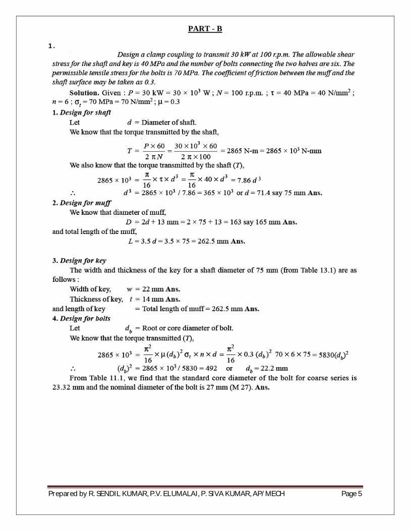
1.
Prepared by R. SENDIL KUMAR, P.V. ELUMALAI, P. SIVA KUMAR, AP/MECH Page 6
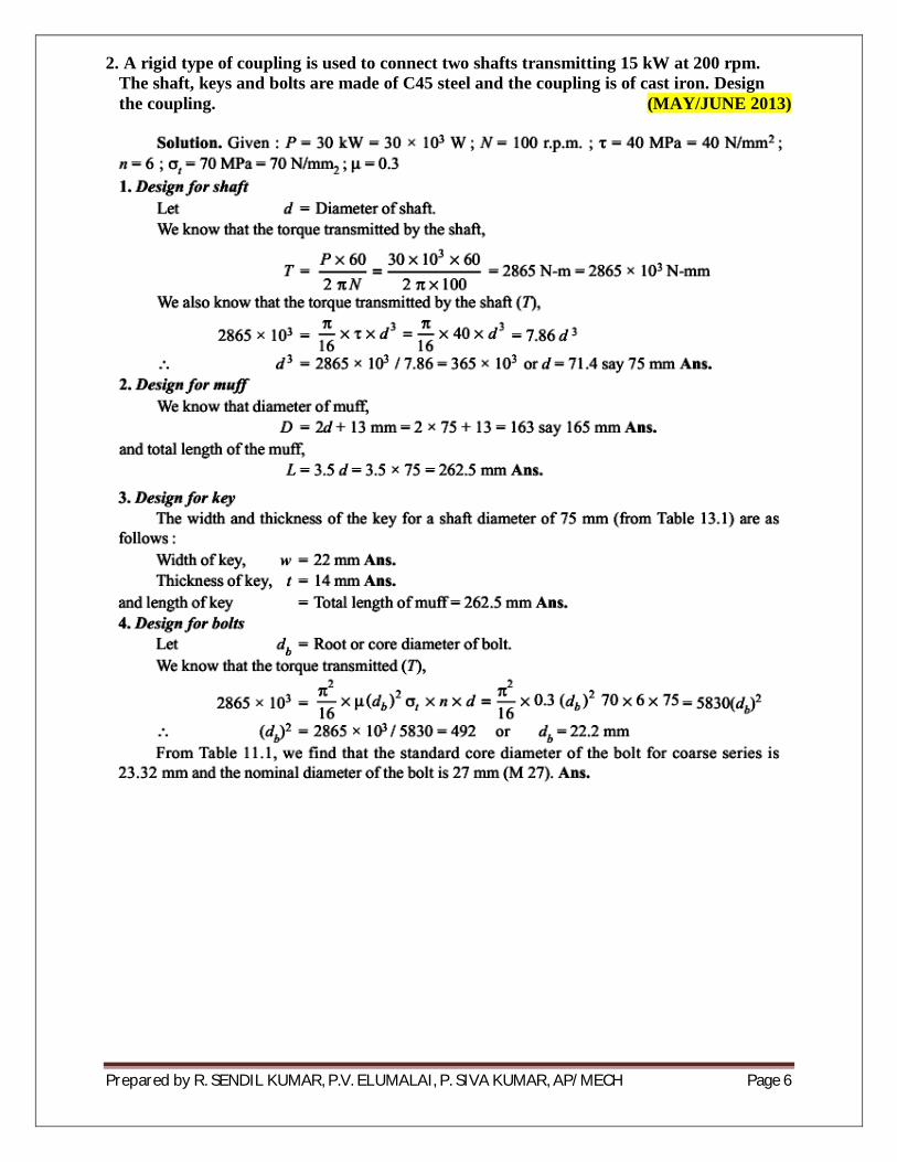
2. A rigid type of coupling is used to connect two shafts transmitting 15 kW at 200 rpm. The shaft, keys and bolts are made of C45 steel and the coupling is of cast iron. Design the coupling. (MAY/JUNE 2013)

Prepared by R. SENDIL KUMAR, P.V. ELUMALAI, P. SIVA KUMAR, AP/MECH Page 7
3. Design a cast iron protective type flange coupling to transmit 15 kW at 900 rpm from an electric motor to a compressor. The service factor may be assumed as 1.35. The following permissible stress may be used: Shear stress for the shaft, bolt and key material = 40 MPa, Crushing stress for bolt and key = 80 MPa, Shear stress for cast iron = 8 MPa. (Nov/Dec 2012)

Prepared by R. SENDIL KUMAR, P.V. ELUMALAI, P. SIVA KUMAR, AP/MECH Page 8

Prepared by R. SENDIL KUMAR, P.V. ELUMALAI, P. SIVA KUMAR, AP/MECH Page 9
4.

Prepared by R. SENDIL KUMAR, P.V. ELUMALAI, P. SIVA KUMAR, AP/MECH Page 10
28. Design a bushed –pin type of flexible coupling to connect a pump shaft to a motor shaft transmitting 32 KW at 960 rpm the overall torque is 20 percent more than mean torque. The material properties are as follows:
(i)The allowable shear and crushing stress for shaft and key material is 40 Mpa and 80 Mpa respectively. (ii) The allowable shear stress for cast iron is 15 Mpa. (iii) The allowable bearing pressure for rubber bush is 0.8 N/mm2. (iv) The material of the pin is same as that of shaft and key. Draw neat sketch of the coupling. (NOV/DEC
2012)

Prepared by R. SENDIL KUMAR, P.V. ELUMALAI, P. SIVA KUMAR, AP/MECH Page 11

Prepared by R. SENDIL KUMAR, P.V. ELUMALAI, P. SIVA KUMAR, AP/MECH Page 12

Prepared by R. SENDIL KUMAR, P.V. ELUMALAI, P. SIVA KUMAR, AP/MECH Page 13
6. Two 35 mm shafts are connected by a flanged coupling. The flanges are fitted with 6 bolts on 25 mm bolt circle. The shafts transmit a torque of 800 N-m at 350 rpm. For the safe stresses mentions below, calculate (i) diameter of bolts, (ii) thickness of flanges, (iii) key dimensions, (iv) hub length and (v) power transmitted. Safe stress for shaft material 63 MPa. Safe stress for bolt material 56 MPa. Safe stress for cast iron coupling 10 MPa and Safe stress for key material 46 MPa. (NOV/DEC 2011)

Prepared by R. SENDIL KUMAR, P.V. ELUMALAI, P. SIVA KUMAR, AP/MECH Page 14
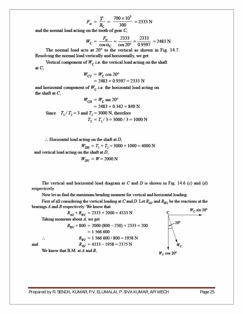
7. A Horizontal nickel steel shaft rests on two bearings, A at the left and B at the right end and carries two gears C and D located at distances of 250 mm and 400 mm respectively from the centre line of the left and right bearings. The pitch diameter of the gear C is 600 mm and that of gear D is 200 mm. The pitch diameter of the gear C is 600 mm and that of gear D is 200 mm. The distance between the centre line of the bearings is 2400mm. The shaft transmits 20 KW at 120 rpm. The power is delivered to the shaft at gear C and is taken out at gear D in such a manner that the tooth pressure FtC of the gear C and FtD of the gear D act vertically downwards.
Find the diameter of the shaft, if the working stress is 100 Mpa in tension and 56 Mpa in shear. The gear C and D weighs 950 N and 350 N respectively. The combined shock and fatigue factors for bending and torsion may be taken as 1.5 and 1.2 respectively. (NOV/DEC 2012)
6250N 16250
A C D B
250 1750 400
2400
2

Prepared by R. SENDIL KUMAR, P.V. ELUMALAI, P. SIVA KUMAR, AP/MECH Page 15
=8725
8725 =
d = 92.5 mm
2]
d = 95.7mm
Taking the larger of the two values, we have d=95.7 mm Say 100 mm.
8. Design a shaft to transmit power from an electric motor to a lathe head stock through a pulley by means of a belt drive. The pulley weights 200 N and is located at 300 mm from the center of the bearing. The diameter of the pulley is 200 mm and the maximum power transmitted is 1 kW at 120 rpm. The angle of lap of the belt is 180o and coefficient of friction between the belt and the pulley is 0.3. the shock arid fatigue factors for bending and twisting are 1.5 and 2 respectively. The allowable shear stress in the shaft may be taken as 35 MPa. (NOV/DEC 2011)

Prepared by R. SENDIL KUMAR, P.V. ELUMALAI, P. SIVA KUMAR, AP/MECH Page 16
9. A steel solid shaft transmitting 15 kW at 200 rpm is supported on two bearings 750 mm apart and has two gears keyed to it. The pinion having 30 teeth of 5 mm module is located 100 min to the left of the right hand bearing and delivers power horizontally to the right. The gear having 100 teeth of 5 mm module is located 150 mm to the right of the left hand bearing and receives power in a vertical direction from below. Using an allowable stress of 54 MPa in shear. Determine the diameter of the shaft. (MAY/JUNE 2013)

Prepared by R. SENDIL KUMAR, P.V. ELUMALAI, P. SIVA KUMAR, AP/MECH Page 17

Prepared by R. SENDIL KUMAR, P.V. ELUMALAI, P. SIVA KUMAR, AP/MECH Page 18

Prepared by R. SENDIL KUMAR, P.V. ELUMALAI, P. SIVA KUMAR, AP/MECH Page 19

Prepared by R. SENDIL KUMAR, P.V. ELUMALAI, P. SIVA KUMAR, AP/MECH Page 20
10.

Prepared by R. SENDIL KUMAR, P.V. ELUMALAI, P. SIVA KUMAR, AP/MECH Page 21
11.

Prepared by R. SENDIL KUMAR, P.V. ELUMALAI, P. SIVA KUMAR, AP/MECH Page 22

Prepared by R. SENDIL KUMAR, P.V. ELUMALAI, P. SIVA KUMAR, AP/MECH Page 23

Prepared by R. SENDIL KUMAR, P.V. ELUMALAI, P. SIVA KUMAR, AP/MECH Page 24
12.
Prepared by R. SENDIL KUMAR, P.V. ELUMALAI, P. SIVA KUMAR, AP/MECH Page 25

Prepared by R. SENDIL KUMAR, P.V. ELUMALAI, P. SIVA KUMAR, AP/MECH Page 26

Prepared by R. SENDIL KUMAR, P.V. ELUMALAI, P. SIVA KUMAR, AP/MECH Page 27

Prepared by R. SENDIL KUMAR, P.V. ELUMALAI, P. SIVA KUMAR, AP/MECH Page 28
13. Design a plain carbon steel center crankshaft for a single acting four stroke, single cylinder engine for the following data: Piston diameter = 200 mm; stroke = 400mm, Maximum combustion pressure = 2.0 N/mm2, Weight of the flywheel = 15 kN, Total belt pull = 3 N, Length of connecting rod = 900 mm, when the crank has turned through 30o from top dead center, the pressure on the piston is 1 N/mm2 and the torque on the crank is maximum. Any other data required for the design may be assumed. (May/June 2012)
14. Design a muff coupling to connect two shafts transmitting 40 kW at 120 rpm. The permissible shear and crushing stress for the shaft and key material are 30 MPa and 80MPa respectively. The material of muff is cast iron with permissible shear stress of 15 MPa. Assume that the maximum torque transmitted is 25% greater than the mean torque. (May/June 2012)


![Dhanalakshmi Project[1]](https://img.pdfslide.net/doc/110x75/550055ad4a7959da6c8b50dd/dhanalakshmi-project1.jpg)