Embed Size (px)
Citation preview
UPDATED CCR FEASIBILITY NOTE
February 2014
DAMHEAD CREEK 2 CCGT POWER STATION

DHC2 Updated CCR Feasibility Note (February 2014) Rev: A 05 February 2014
Page 2 of 33
Name Job Title Signature Date
Prepared Roberto Carnero Performance
Engineer
05.02.2014
Checked Raul Gómez Performance
Engineer
05.02.2014
Approved Ian Mackay Project Manager
05.02.2014
AMENDMENT RECORD
Issue Date Issued Date Effective Purpose of Issue and Description of Amendment
A 05.02.2014 N/A Initial Edition
DHC2 Updated CCR Feasibility Note (February 2014) Rev: A 05 February 2014
Page 3 of 33
TABLE OF CONTENTS EXECUTIVE SUMMARY ............................................................................ 5
1. Introduction ...................................... ............................................. 6
1.1. General ........................................... ................................................ 6
1.2. Overview .......................................... .............................................. 6
1.3. The Purpose of a CCR Feasibility Study ............ ......................... 7
1.4. Purpose of this Document .......................... .................................. 9
2. Legal Context and Methodology ..................... ........................... 11
3. Proposed Development .............................. ................................ 12
3.1. Damhead Creek 2 - The Site ........................ ............................... 12
3.2. Damhead Creek 2 - The Proposed Configuration and CO 2
Output ............................................ .......................................................... 13
3.3. Estimation of the size of the CCS Chain ........... ........................ 15
4. Proposed Carbon Capture Plant Technology .......... ................. 18
5. Technical Assessment – CCS Space Requirements...... .......... 19
5.1. Update to the previous CCR Studies ................ ......................... 19
5.2. Illustrative Site Layout .......................... ...................................... 21
6. Technical Assessment – Retrofitting and Integration of CCS 22
7. Technical Assessment – CO2 Storage Areas .......... ................. 23
7.1. Proposed Storage Areas ............................ ................................ 23
8. Technical Assessment – CO2 Transport .............. .................... 25
9. Economic Assessment ............................... ................................ 26
10. Requirement for Hazardous Substances Consent ...... ............. 27
11. Conclusions ....................................... .......................................... 28

DHC2 Updated CCR Feasibility Note (February 2014) Rev: A 05 February 2014
Page 4 of 33
Table: Table 3.1: Maximum CO2 and Flue Gas Intensities for Various Sized CCGT Power Plant Technologies
Table 3.2: Sizing of CCS Chain for Option A
Table 5.1: Summary of CCR Space Requirement for DHC2
Table 7.1: Percentage CO2 Storage Requirements of DHC2
Table 7.2: Additional CO2 Storage Areas in the SNS region
Figures: Figure 1: DHC2 Development General Arrangement Plan (2014)
Figure 2: Illustrative Site Area For Carbon Capture
DHC2 Updated CCR Feasibility Note (February 2014) Rev: A 05 February 2014
Page 5 of 33
EXECUTIVE SUMMARY
Following discussions with Original Equipment Manufacturers, and taking into account the latest gas
turbine technology, the output of Damhead Creek 2 (DHC2) has the possibility of being increased to
around 1200MW of power generation capacity with improved efficiency.
ScottishPower (DCL) Ltd. are applying for a variation to the Section 36 Consent from the Department of
Energy and Climate Change by to increase the electrical output from current 1098MW to 1200MW (at
ISO conditions). The variation application is undertaken in accordance with The Electricity Generating
Stations (Variation of Consents) (England and Wales) Regulations 2013 which came into force in July
2013.
If implemented, the increase in electrical capacity output would ultimately include the installation of
higher capacity gas turbine units with higher efficiency ratings which would reduce the CO2 intensity
factor of DHC2, i.e. the CO2 production per each MWh exported to the grid.
This Document has been prepared to highlight the potential impact of this change / modification and
demonstrate the ongoing compliance with the requirements of both the EU Carbon Capture and Storage
(CCS) Directive and the UK Government’s Carbon Capture Readiness (CCR) Guidance.
This Document largely follows the sequence of the previous CCR Studies submitted by ScottishPower in
June 2009, May 2010 and January 2013. This Document constitutes an update of the last report, the
January 2013 “Updated CCR Feasibility Note”.
This Document taken together with these previous CCR Studies has demonstrated the following:
• “That sufficient space is available on or near the site to accommodate carbon capture
equipment in the future;
• The technical feasibility of retrofitting their chosen carbon capture technology;
• That a suitable area of deep geological storage off shore exits for the storage of captured CO2
from the proposed power station;
• The technical feasibility of transporting the captured CO2 to the proposed storage area; and,
• The likelihood that it will be economically feasible within the power station’s lifetime, to link it to
the full CCS chain, covering retrofitting of carbon capture equipment, transport and storage”.
In conclusion, it is both technically and economically feasible to retrofit a CCS Chain to DHC2 within its
35 year operating lifetime.
DHC2 Updated CCR Feasibility Note (February 2014) Rev: A 05 February 2014
Page 6 of 33
1. Introduction
1.1. General
This Updated Carbon Capture Ready (CCR) Feasibility Note has been undertaken by Iberdrola
Engineering and Construction (IEC) on behalf of ScottishPower (DCL) Ltd. (ScottishPower) to support
the application for consent variation for the proposed Damhead Creek 2 Combined Cycle Gas Turbine
(CCGT) Power Station (DHC2) in accordance with The Electricity Generating Stations (Variation of
Consents) (England and Wales) Regulations 2013 which came into force in July 2013.
This Document largely follows the sequence of the previous CCR Studies submitted by ScottishPower:
• Damhead Creek 2 CCR Feasibility Study (June 2009) prepared by Parsons Brinckerhoff
• Damhead Creek 2 Consolidated CCR Feasibility Study (May 2010) prepared by Parsons
Brinckerhoff
• Damhead Creek 2 Updated CCR Feasibility Note (January 2013) prepared by Parsons
Brinckerhoff
This Document constitutes an update of the last report submitted by ScottishPower, the January 2013
Updated CCR Feasibility Note. The structure of this preceding report has been maintained for clarity and
to maintain continuity.
1.2. Overview
In June 2009, ScottishPower submitted an application for consent under Section 36 of the Electricity Act
1989 to the Department of Energy and Climate Change (DECC) to construct a Combined Cycle Gas
Turbine (CCGT) power plant to be known as Damhead Creek 2 (DHC2). In addition, a direction that
planning permission be deemed to be granted under Section 90 of the Town and Country Planning Act
1990 was also sought.
The application was accompanied by, amongst other documents / studies, a Carbon Capture Ready
(CCR) Feasibility Study (the June 2009 CCR Feasibility Study).
Further to the June 2009 CCR Feasibility Study, in May 2010 a consolidated CCR Feasibility Study (the
May 2010 CCR Feasibility Study) was prepared to provide additional information to address questions
DHC2 Updated CCR Feasibility Note (February 2014) Rev: A 05 February 2014
Page 7 of 33
posed by DECC and the Environment Agency (EA) during their processing of the application, and to
satisfy the requirements of the final CCR Guidance1 published in November 2009.
Consent under Section 36 of the Electricity Act 1989 for DHC2 was granted in January 2011. In the time
since the original consent was granted additional capacity has been afforded to the project by DECC
which will result in increased output from 1000MW to 1098MW (at ISO conditions). Consent to increase
the output to 1098MW was granted in July 2012 by DECC.
The request for an increase in permitted generation capacity of DHC2 from 1000MW to 1098MW to
DECC was accompanied in January 2013 by the updated report Updated CCR Feasibility Note (the
January 2103 Updated CCR Feasibility Note2) to demonstrate the potential changes / modifications
would remain fully compliant with the requirements of both the EU CCS Directive and the UK
Government’s CCR Guidance.
Accordingly, that document largely followed the sequence of the June 2009 and May 2010 CCR
Feasibility Studies. The revised Carbon Capture Readiness report with regard to the 1098MW power
output was approved by DECC in March 2013.
1.3. The Purpose of a CCR Feasibility Study
Background
On 17th December 2008, the European Union (EU) agreed the text of a new directive on the geological
storage of carbon dioxide. On 5th June 2009, this text was published as the Directive on the geological
storage of carbon dioxide (Directive 2009/31/EC) (the Carbon Capture and Storage (CCS) Directive) in
the Official Journal of the European Union and came into force on 25th June 2009.
The CCS Directive requires an amendment to Directive 2001/80/EC (commonly known as the Large
Combustion Plants Directive (LCPD)) such that Member States are to ensure that operators of all
combustion plants with an electrical capacity of 300 megawatts (MW) or more (and for which the
construction / operating licence was granted after the date of the CCS Directive) have assessed whether
the following conditions are met:
• Suitable storage sites for carbon dioxide (CO2) are available;
• Transport facilities to transport captured CO2 to the storage sites are technically and
economically feasible; and,
• It is technically and economically feasible to retrofit for the capture of CO2.
1 Carbon Capture Readiness (CCR): A Guidance Note for Section 36 Electricity Act 1989 Consent Applications (DECC,
November 2009). 2 Damhead Creek 2 Updated CCR Feasibility Note (January 2013) prepared by Parsons Brinckerhoff.
DHC2 Updated CCR Feasibility Note (February 2014) Rev: A 05 February 2014
Page 8 of 33
The assessment of whether these conditions are met is to be submitted to the relevant competent
authority, who use the assessment (and other available information) in their decision-making process. If
the conditions are met, the competent authority is to ensure that suitable space is set aside for the
equipment necessary to capture and compress CO2.
It should also be noted that the requirement for the assessment is also included in the more recent
Directive on industrial emissions (integrated pollution prevention and control) (Directive 2010/75/EU)
(the Industrial Emissions Directive (IED)).
In the UK the relevant competent authority (in respect of energy matters) is the Department of Energy
and Climate Change (DECC). DECC must ensure the requirements of the relevant EU Directives are
implemented.
UK Government’s CCR Policy
In June 2008, the UK Government published a consultation document “Towards Carbon Capture and
Storage” to seek views on the steps it could take to prepare for and support both the development and
deployment of carbon capture technologies. A response to this consultation was published in April 2009,
alongside information on the UK Government’s CCR Policy and draft Guidance for applicants seeking
consent for new combustion power plants at or over 300MWe3 (the draft CCR Guidance).
The CCR Policy applies to new combustion power plants with an electrical capacity of 300MW or more,
with effect from 23rd April 2009. Under the CCR Policy, all combustion power plants with an electrical
capacity of 300MW or more must be CCR and must set space aside to accommodate future carbon
capture equipment.
The draft CCR Guidance was subject to an eight week consultation period which ended on 22nd June
2009. The responses from the consultation period were incorporated into the finalised CCR Guidance,
which was published in November 2009.
Following the publication of the CCR Guidance, the indicative CCR space requirement was reviewed by
Imperial College, London4. The Imperial College, London review resulted in the reduction of the
indicative CCR space requirement for a CCGT power plant with post-combustion capture by 36%.
Further information is provided in Section 5 (‘Technical Assessment – CCS Space Requirements‘).
3 Guidance on Carbon Capture Readiness and Applications under Section 36 of the Electricity Act 1989 (DECC, 2009) 4 Available at: http://www.decc.gov.uk/en/content/cms/meeting_energy/consents_planning/electricity/electricity.aspx
DHC2 Updated CCR Feasibility Note (February 2014) Rev: A 05 February 2014
Page 9 of 33
UK Government’s CCR Policy Requirements
Under the CCR Policy, the CCR Guidance states (at paragraph 7) that applicants will be required to
demonstrate:
• “That sufficient space is available on or near the site to accommodate carbon capture
equipment in the future;
• The technical feasibility of retrofitting their chosen carbon capture technology;
• That a suitable area of deep geological storage off shore exits for the storage of captured CO2
from the proposed power station;
• The technical feasibility of transporting the captured CO2 to the proposed storage area; and,
• The likelihood that it will be economically feasible within the power station’s lifetime, to link it to
the full CCS chain, covering retrofitting of carbon capture equipment, transport and storage”.
Further to this: “if Applicant’s proposals for operational CCS involves the use of hazardous substances,
they may be required to apply for Hazardous Substances Consent (HSC). In such circumstances they
should do so at the same time as they apply for Section 36 Consent”.
1.4. Purpose of this Document
In recent years, the gas turbine Original Equipment Manufacturers (OEMs) have introduced to the
market advanced models of gas turbines with larger capacity and higher efficiency ratings. Following
discussions with OEMs, taking into account the latest enhancements in these gas turbine models, the
output of DHC2 has the possibility of being increased to around 1200MW of power generation capacity
with higher efficiency.
In order to not restrict this potential alternative at the time the CCGT power plant is being contracted, a
variation to the Section 36 Consent is being sought from DECC by ScottishPower for a potential
increase in the electrical capacity output range of DHC2 from current 1098MW to 1200MW (at ISO
conditions). The potential change / modification as a result of increasing electrical output to 1200MW
can be summarised as:
• If implemented, the increase in electrical capacity output would ultimately include the installation
of higher capacity gas turbine units with higher efficiency ratings which would increase the total
CO2 output of DHC2 but the CO2 emission rate per each MWh exported to the grid would be
reduced (i.e. the CO2 intensity factor would be lower). For the purposes of this Document, a
‘worst case’ scenario is presented based on the original gas turbine units and efficiency ratings
applied to the maximum theoretical electrical output of DHC2, yielding the maximum possible
CO2 and flue gas flow rates.

DHC2 Updated CCR Feasibility Note (February 2014) Rev: A 05 February 2014
Page 10 of 33
This Document seeks to demonstrate the new potential increase in power capacity would remain fully
compliant with the requirements of both the EU CCS Directive and the UK Government's CCR
Guidance.
This Document has been prepared to highlight the potential impact of this potential change / modification
and to demonstrate that it could still be both technically and economically feasible to retrofit a CCS
Chain to DHC2 within its 35 year operating lifetime. Accordingly, this Document largely follows the
sequence of the June 2009 and May 2010 CCR Feasibility Studies and the more recent January 2013
Updated CCR Feasibility Note. Where no changes or supplementary information are deemed
necessary, this is stated at the beginning of the section.

DHC2 Updated CCR Feasibility Note (February 2014) Rev: A 05 February 2014
Page 11 of 33
2. Legal Context and Methodology
There has been no change to the legislative framework since consent was granted for DHC2 and
therefore no changes or supplementary information are required for this section.
DHC2 Updated CCR Feasibility Note (February 2014) Rev: A 05 February 2014
Page 12 of 33
3. Proposed Development
3.1. Damhead Creek 2 - The Site
Consented DHC2 Site
The Section 36 and deemed planning permission for DHC2 identified the following areas as forming the
consented development site:
Area 1. 6.2 hectares (ha) of land lying to the east of the existing Damhead Creek CCGT
Power Station. This area is the location of the proposed DHC2.
Area 2. 3.6ha of land lying to the north-west of the existing Damhead Creek CCGT Power
Station. This area was the original location of the proposed 400kV electrical substation
(this solution has been ruled out)5.
Area 3. 14ha of land lying to the north-east of the existing Damhead Creek CCGT Power
Station. Approximately 7.5ha of this land to be used temporarily for car parking and
the storage of materials / equipment during construction, and will subsequently be set
aside for the equipment necessary to capture and compress CO2. The remainder of
the land to be dedicated to ecological mitigation, including additional ponds and
habitat enhancement.
In addition, an extensive area of ecological mitigation land (approximately 26ha) which has been
established and maintained as part of the existing Damhead Creek CCGT Power Station development
adjoins the DHC2 development site.
Current proposal 2014
Following the granting of Section 36 Consent, and further technical assessment of the development
progressed, ScottishPower considered a modification / change in the area set aside for the equipment
necessary to capture and compress CO2 (i.e. changes / modifications to Area 3).
The existing area of ecological mitigation known as the Wildlife Creation Area (WCA), effectively
separated the DHC2 site (Area 1) from the laydown and construction area which would ultimately
become the CCR area (Area 3). It was recognised that including the WCA as part of the development
site for DHC2 and CCR land would allow for a simpler construction of DHC2 by allowing movement and
operations directly between these two areas. ScottishPower therefore sought to change the use of the
WCA to include this area as part of the development site for DHC2.
5 The electricity generated in this case will be exported to the National Grid via the existing Kingsnorth substation lying to the
south west of the existing Damhead Creek CCGT Power Station.

DHC2 Updated CCR Feasibility Note (February 2014) Rev: A 05 February 2014
Page 13 of 33
The WCA was originally part of a Section 106 agreement associated with the construction of the now
operational Damhead Creek CCGT Power Station. These design modifications have emerged through
the detailed design process that has been undertaken in the time since DHC2 was originally consented
in 2011, and represent minor revisions that better allows for the construction of DHC2.
A Planning Application for Change of Use and supporting information was submitted to Medway Council
in September 2012 and planning permission for a change of use of the WCA was granted by Medway
Council to ScottishPower in July 2013. This allowed an additional 2.4ha of land to be available for DHC2
and the CCR land as necessary.
A consequence of changing the use of the WCA, was that suitable compensatory mitigation land
required to be provided by ScottishPower. Therefore part of Area 3 was identified for additional
ecological mitigation resulting in approximately 5.37ha being available for use as temporarily for car
parking and the storage of materials / equipment during construction, and then would subsequently be
set aside for the equipment necessary to capture and compress CO2. This represented a reduction of
2.13ha to CCR area.
In addition to this, ScottishPower retains an additional strip of land extending to approximately 0.7ha that
it is located between Area 1 and Area 3 that can also be utilised for CCR purposes.
Currently therefore the total space within Area 3 to be dedicated for the equipment necessary to capture
and compress CO2 would be approximately 6.1ha comprising 5.37ha within Area 3 and the additional
0.7ha strip of land.
The general arrangement plan can be seen in Figure 1.
3.2. Damhead Creek 2 - The Proposed Configuration and
CO2 Output
Subsequent to the June 2009 and May 2010 CCR Feasibility Studies and recent January 2013 Updated
CCR Feasibility Note, ScottishPower have considered a potential increase in the electrical capacity
output range of DHC2 from 1098MW to 1200MW (at ISO conditions), and have submitted an application
under Section 36C of the Electricity Act 1989 to seek to raise the generated output of the CCGT to
1200MW. Based on this potential increase in capacity of the CCGT, the estimated CO2 and flue gas flow
rates have been recalculated and presented in this updated CCR Report.
DHC2 Updated CCR Feasibility Note (February 2014) Rev: A 05 February 2014
Page 14 of 33
As carbon capture technology is essentially blind to the details of the upstream power generation
process, the only output required for the sizing of the equipment necessary to capture and compress
CO2 are details of the CO2 and flue gas flow rates and the temperature of the flue gas.
There are two OEMs that commercialise gas turbine units in the range for the new proposed electrical
output of DHC2. Internal calculations have been performed from the information provided by these
OEMs in order to determine the CO2 and flue gas intensity factors for their proposed CCGT power plant
technologies. These intensity factors have been used in this updated CCR Feasibility Report to estimate
maximum and average CO2 and flue gas flow rates for DHC2.
The CO2 and flue gas intensity factors were calculated assuming a power plant configuration of one (1)
multi-shaft CCGT units assuming value for two (2) gas turbines, one (1) steam turbine with a triple
pressure reheat steam cycle and one (1) Air Cooled Condenser (ACC). However, the values basically
will be the same for alternative power plant configuration of two single shaft CCGT units for the same
electrical power output. The decision about the configuration of the CCGT power plant, either multi-shaft
or two (2) single-shafts, is not relevant with regard to the environmental impact and specifically the
carbon emission; it is principally a decision based on different parameters e.g. promoter’s previous
operational experience and layout restrictions or other specific operational considerations. The drawings
of the CCGT power plant layout are based on the multi-shaft configuration.
However, it should be noted that as full details of the final design of DHC2 are not yet available, as a
vendor has not yet been chosen and the gas turbine model is not selected, estimation was undertaken
using a range of different turbine technologies currently available. In addition it should be noted that the
power plant configuration assumed may not be that used in the final design of DHC2.
Table 3.1 below indicates the CO2 and flue gas intensity factors and power ratios for the various sized
CCGT power plant technologies available in the power output range.
The power ratio is used to determine the maximum and average flow rates. The power ratio is the ratio
between the total electrical output of DHC2 at typical site rated conditions (11.3°C) and the total
electrical output of DHC2 under reduced atmospheric temperature conditions6 (-10°C). Accordingly, the
power ratio is used to estimate a maximum CO2 flow rate which could be expected from DHC2 under
worst case conditions.
6 A lower atmospheric temperature will increase the total electrical output of power generating plant and with this comes a
corresponding increase in CO2 flow rate.
DHC2 Updated CCR Feasibility Note (February 2014) Rev: A 05 February 2014
Page 15 of 33
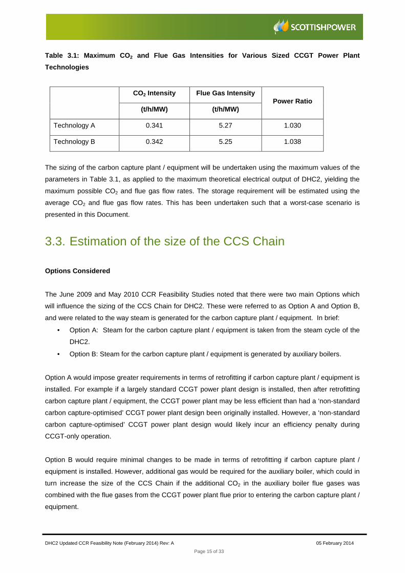
Table 3.1: Maximum CO 2 and Flue Gas Intensities for Various Sized CCGT Po wer Plant
Technologies
CO2 Intensity Flue Gas Intensity Power Ratio
(t/h/MW) (t/h/MW)
Technology A 0.341 5.27 1.030
Technology B 0.342 5.25 1.038
The sizing of the carbon capture plant / equipment will be undertaken using the maximum values of the
parameters in Table 3.1, as applied to the maximum theoretical electrical output of DHC2, yielding the
maximum possible CO2 and flue gas flow rates. The storage requirement will be estimated using the
average CO2 and flue gas flow rates. This has been undertaken such that a worst-case scenario is
presented in this Document.
3.3. Estimation of the size of the CCS Chain
Options Considered
The June 2009 and May 2010 CCR Feasibility Studies noted that there were two main Options which
will influence the sizing of the CCS Chain for DHC2. These were referred to as Option A and Option B,
and were related to the way steam is generated for the carbon capture plant / equipment. In brief:
• Option A: Steam for the carbon capture plant / equipment is taken from the steam cycle of the
DHC2.
• Option B: Steam for the carbon capture plant / equipment is generated by auxiliary boilers.
Option A would impose greater requirements in terms of retrofitting if carbon capture plant / equipment is
installed. For example if a largely standard CCGT power plant design is installed, then after retrofitting
carbon capture plant / equipment, the CCGT power plant may be less efficient than had a ‘non-standard
carbon capture-optimised’ CCGT power plant design been originally installed. However, a ‘non-standard
carbon capture-optimised’ CCGT power plant design would likely incur an efficiency penalty during
CCGT-only operation.
Option B would require minimal changes to be made in terms of retrofitting if carbon capture plant /
equipment is installed. However, additional gas would be required for the auxiliary boiler, which could in
turn increase the size of the CCS Chain if the additional CO2 in the auxiliary boiler flue gases was
combined with the flue gases from the CCGT power plant flue prior to entering the carbon capture plant /
equipment.
DHC2 Updated CCR Feasibility Note (February 2014) Rev: A 05 February 2014
Page 16 of 33
Whilst both Option A and Option B are available for DHC2, Option A was the main focus of the June
2009 and May 2010 CCR Feasibility Studies and the more recent January 2013 Update CCR Feasibility
Note, following discussions with the Environment Agency. Option A remains the main focus of this
Document.
Size of the CCS Chain
It is expected that the carbon capture plant / equipment installed would capture up to 90% of the CO2 in
the flue gases. However, the actual amount will be dependent upon the temperature of the carbon
capture plant / equipment and the amount of process cooling available.
In addition (and similar to the previous CCR reports: June 2009 and May 2010 CCR Feasibility Studies
and the January 2013 Updated CCR Feasibility Note), this updated CCR Feasibility Study has assumed
that the carbon capture plant / equipment would incorporate a gas-gas re-heater. This is, in effect, a
heat exchanger which cools down the flue gases entering the carbon capture plant / equipment using
the flue gases exiting the carbon capture plant / equipment. This results in a higher ‘clean gas’ exit
temperature, improving dispersion in the air, and lower process cooling requirements of the carbon
capture plant / equipment. However, a gas-gas re-heater may result in some leakage of flue gas from
the incoming side to the exit side. Again similar to the June 2009 and May 2010 CCR Feasibility Studies
and the January 2013 Updated CCR Feasibility Note, for the purposes of this updated CCR Feasibility
Study, this leakage has been assumed to be 3% which represents the typical value for such plant /
equipment in a new and clean condition. However, over time, the leakage will increase slightly, resulting
in the carbon capture plant having spare capacity.
Option A
The sizing of the CCS Chain for Option A (including capture, compression / liquefaction, transport and
storage) is based on the information presented in Table 3.2.
DHC2 Updated CCR Feasibility Note (February 2014) Rev: A 05 February 2014
Page 17 of 33
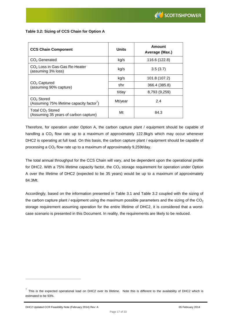
Table 3.2: Sizing of CCS Chain for Option A
CCS Chain Component Units Amount
Average (Max.)
CO2 Generated kg/s 116.6 (122.8)
CO2 Loss in Gas-Gas Re-Heater (assuming 3% loss)
kg/s 3.5 (3.7)
CO2 Captured (assuming 90% capture)
kg/s 101.8 (107.2)
t/hr 366.4 (385.8)
t/day 8,793 (9,259)
CO2 Stored (Assuming 75% lifetime capacity factor7)
Mt/year 2.4
Total CO2 Stored (Assuming 35 years of carbon capture)
Mt 84.3
Therefore, for operation under Option A, the carbon capture plant / equipment should be capable of
handling a CO2 flow rate up to a maximum of approximately 122.8kg/s which may occur whenever
DHC2 is operating at full load. On this basis, the carbon capture plant / equipment should be capable of
processing a CO2 flow rate up to a maximum of approximately 9,259t/day.
The total annual throughput for the CCS Chain will vary, and be dependent upon the operational profile
for DHC2. With a 75% lifetime capacity factor, the CO2 storage requirement for operation under Option
A over the lifetime of DHC2 (expected to be 35 years) would be up to a maximum of approximately
84.3Mt.
Accordingly, based on the information presented in Table 3.1 and Table 3.2 coupled with the sizing of
the carbon capture plant / equipment using the maximum possible parameters and the sizing of the CO2
storage requirement assuming operation for the entire lifetime of DHC2, it is considered that a worst-
case scenario is presented in this Document. In reality, the requirements are likely to be reduced.
7 This is the expected operational load on DHC2 over its lifetime. Note this is different to the availability of DHC2 which is
estimated to be 93%.

DHC2 Updated CCR Feasibility Note (February 2014) Rev: A 05 February 2014
Page 18 of 33
4. Proposed Carbon Capture Plant Technology
No change is proposed to the carbon capture plant technology and therefore no changes or
supplementary information are deemed necessary.
DHC2 Updated CCR Feasibility Note (February 2014) Rev: A 05 February 2014
Page 19 of 33
5. Technical Assessment – CCS Space
Requirements
5.1. Update to the previous CCR Studies
Table 1 in the CCR Guidance provides an indicative CCR space requirement based on a 500MW (net)
power plant. For a CCGT power plant with post-combustion carbon capture, the indicative CCR space
requirement was 3.75ha for 500MW. Subsequent to the publication of the CCR Guidance, the indicative
CCR space requirement was reviewed by Imperial College, London8.
The Imperial College, London review resulted in the reduction of the indicative CCR space requirement
for a CCGT power plant with post-combustion capture by 36%. Therefore, the corrected indicative CCR
space requirement is 2.4ha for 500MW.
In addition, it is noted that the Imperial College, London review further detailed additional scope for a
reduction of the indicative CCR space requirement for a CCGT power plant with post-combustion
capture of approximately 50% (including the reduction of 36%) considering technology advances and
layout optimisation (e.g. assuming one carbon capture train per gas turbine train). In addition, it is also
noted that the Imperial College, London review further detailed, at the Appendix A1 – that retrofitting of
carbon capture plant / equipment would be site specific and where limited space is available, efforts may
then require a unique approach to utilise the three-dimensional space available (for example, a study
has demonstrated that vertical utilisation of a smaller space can still accommodate the required carbon
capture plant / equipment in a safe, operable and maintainable manner). However, such a reduction can
only be justified on the basis of a detailed engineering design and it has not been necessary to consider
this approach for the DHC2 CCR space requirements.
Accordingly, based on both the original (superseded) and the corrected indicative CCR space
requirements, Table 5.1 presents a summary of CCR space requirement for DHC2.
8 Available at: http://www.decc.gov.uk/en/content/cms/meeting_energy/consents_planning/electricity/electricity.aspx
DHC2 Updated CCR Feasibility Note (February 2014) Rev: A 05 February 2014
Page 20 of 33
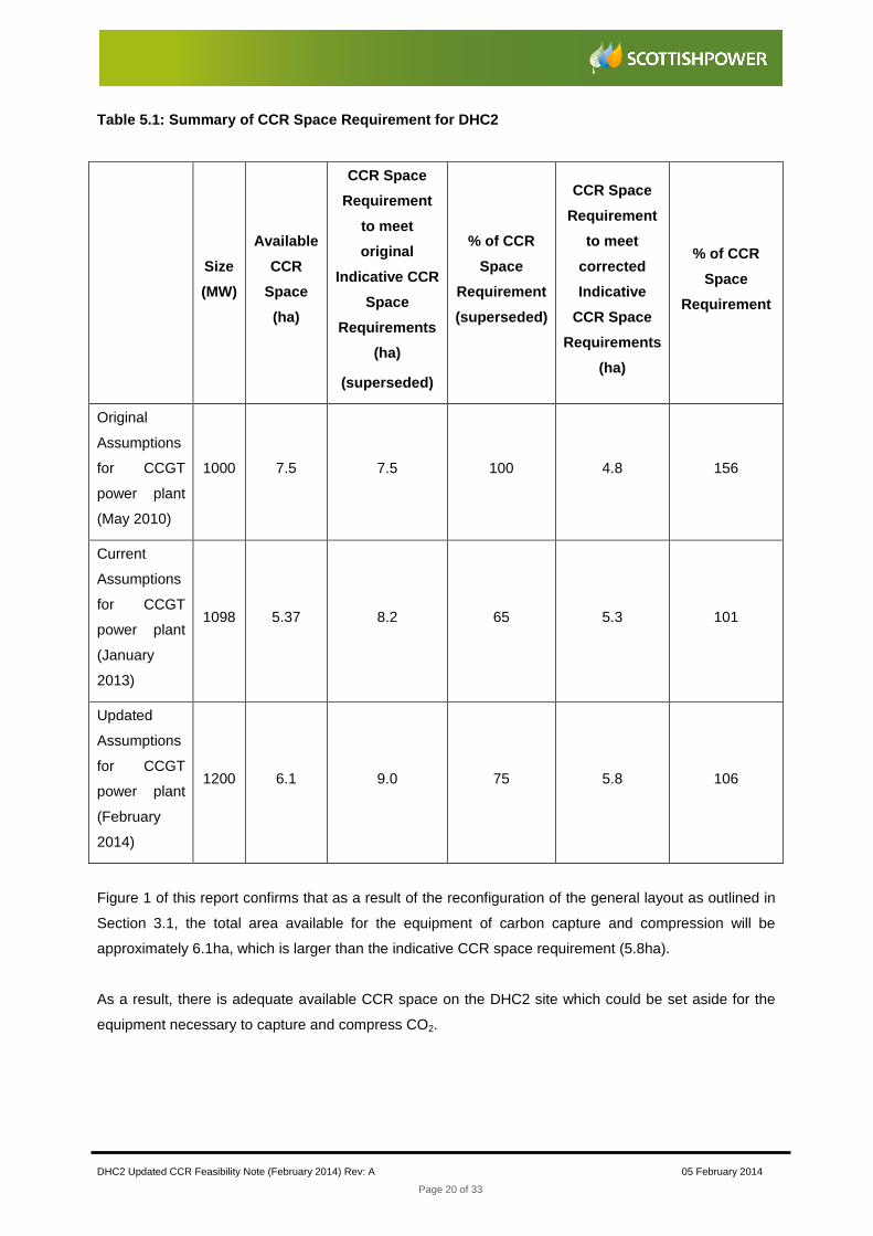
Table 5.1: Summary of CCR Space Requirement for DHC 2
Size
(MW)
Available
CCR
Space
(ha)
CCR Space
Requirement
to meet
original
Indicative CCR
Space
Requirements
(ha)
(superseded)
% of CCR
Space
Requirement
(superseded)
CCR Space
Requirement
to meet
corrected
Indicative
CCR Space
Requirements
(ha)
% of CCR
Space
Requirement
Original
Assumptions
for CCGT
power plant
(May 2010)
1000 7.5 7.5 100 4.8 156
Current
Assumptions
for CCGT
power plant
(January
2013)
1098 5.37 8.2 65 5.3 101
Updated
Assumptions
for CCGT
power plant
(February
2014)
1200 6.1 9.0 75 5.8 106
Figure 1 of this report confirms that as a result of the reconfiguration of the general layout as outlined in
Section 3.1, the total area available for the equipment of carbon capture and compression will be
approximately 6.1ha, which is larger than the indicative CCR space requirement (5.8ha).
As a result, there is adequate available CCR space on the DHC2 site which could be set aside for the
equipment necessary to capture and compress CO2.
DHC2 Updated CCR Feasibility Note (February 2014) Rev: A 05 February 2014
Page 21 of 33
5.2. Illustrative Site Layout
In order to demonstrate that space is available and suitable for DHC2 to be considered CCR, an
illustrative site layout has been prepared which indicates:
• The location of the carbon capture plant / equipment;
• The location of the CO2 compression equipment;
• The location of the chemical storage facilities; and,
• The exit point for the CO2 pipeline.
The illustrative site layout can be seen in Figure 2.
However, whilst the illustrative site layout is drawn to scale, it should be noted that this is not a detailed
design specification. Therefore the layout is illustrative only and outlines areas required for major plant /
equipment items and other additional buildings.
The space requirement for the cooling system has been extended in the layout as a conservative
approach. Potential reduction can only be justified on the basis of a detailed engineering design.
In addition, the tender specifications for DHC2 will include requirements to ensure that the power plant is
CCR.

DHC2 Updated CCR Feasibility Note (February 2014) Rev: A 05 February 2014
Page 22 of 33
6. Technical Assessment – Retrofitting and
Integration of CCS
No changes or supplementary information are deemed necessary.
It should be noted that with regards to the Point C6 (Steam Cycle) and Point C7 (Cooling Water
System), no significant alterations to the conclusions of the June 2009 CCR Feasibility Study or May
2010 Feasibility Study are anticipated.
DHC2 Updated CCR Feasibility Note (February 2014) Rev: A 05 February 2014
Page 23 of 33
7. Technical Assessment – CO2 Storage Areas
7.1. Proposed Storage Areas
In order to determine potential CO2 storage areas, it is necessary to have an idea of the CO2 storage
requirements of DHC2. In line with the calculations detailed in Table 3.2 for Option A, the CO2 storage
requirements of DHC2 would be up to a maximum of approximately 84.3Mt of CO2.
Based on the DTI Study 2006 (provided in the CCR Guidance), the Hewet (L Bunter) and Leman gas
fields in the South North Sea Basin (SNS) are potential storage areas. The Hewet (L Bunter) gas field
has a capacity of 237Mt CO2 and the Leman gas field has a capacity of 1203Mt CO2.
Accordingly, Table 7.1 illustrates the percentage CO2 storage requirements of DHC2 on these two gas
fields.
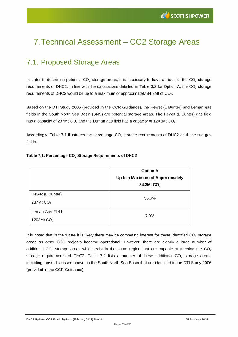
Table 7.1: Percentage CO 2 Storage Requirements of DHC2
Option A
Up to a Maximum of Approximately
84.3Mt CO2
Hewet (L Bunter)
237Mt CO2 35.6%
Leman Gas Field
1203Mt CO2 7.0%
It is noted that in the future it is likely there may be competing interest for these identified CO2 storage
areas as other CCS projects become operational. However, there are clearly a large number of
additional CO2 storage areas which exist in the same region that are capable of meeting the CO2
storage requirements of DHC2. Table 7.2 lists a number of these additional CO2 storage areas,
including those discussed above, in the South North Sea Basin that are identified in the DTI Study 2006
(provided in the CCR Guidance).
DHC2 Updated CCR Feasibility Note (February 2014) Rev: A 05 February 2014
Page 24 of 33
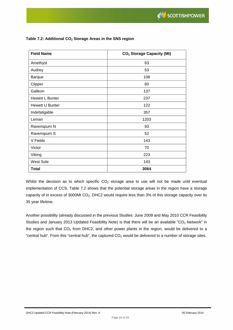
Table 7.2: Additional CO 2 Storage Areas in the SNS region
Field Name CO2 Storage Capacity (Mt)
Amethyst 63
Audrey 53
Barque 108
Clipper 60
Galleon 137
Hewett L Bunter 237
Hewett U Bunter 122
Indefatigable 357
Leman 1203
Ravenspurn N 93
Ravenspurn S 52
V Fields 143
Victor 70
Viking 223
West Sole 143
Total 3064
Whilst the decision as to which specific CO2 storage area to use will not be made until eventual
implementation of CCS, Table 7.2 shows that the potential storage areas in the region have a storage
capacity of in excess of 3000Mt CO2. DHC2 would require less than 3% of this storage capacity over its
35 year lifetime.
Another possibility (already discussed in the previous Studies: June 2009 and May 2010 CCR Feasibility
Studies and January 2013 Updated Feasibility Note) is that there will be an available “CO2 Network” in
the region such that CO2 from DHC2, and other power plants in the region, would be delivered to a
“central hub”. From this “central hub”, the captured CO2 would be delivered to a number of storage sites.

DHC2 Updated CCR Feasibility Note (February 2014) Rev: A 05 February 2014
Page 25 of 33
8. Technical Assessment – CO2 Transport
No changes or supplementary information are deemed necessary.

DHC2 Updated CCR Feasibility Note (February 2014) Rev: A 05 February 2014
Page 26 of 33
9. Economic Assessment
No changes or supplementary information are deemed necessary.

DHC2 Updated CCR Feasibility Note (February 2014) Rev: A 05 February 2014
Page 27 of 33
10. Requirement for Hazardous Substances
Consent
No changes or supplementary information are deemed necessary.

DHC2 Updated CCR Feasibility Note (February 2014) Rev: A 05 February 2014
Page 28 of 33
11. Conclusions
Following the granting of consent under Section 36 of the Electricity Act 1989 for DHC2 in January 2011,
ScottishPower have considered potential modification to the original assumptions detailed in the
previous CCR Studies (June 2009 and May 2010 CCR Feasibility Studies and January 2013 Updated
CCR Feasibility Note).
The potential modification can be summarised as:
• An increase in the electrical capacity output range of DHC2 from 1098MW to 1200MW (at ISO
conditions). If implemented, the increase in electrical capacity output would ultimately include
the installation of higher capacity gas turbine units with higher efficiency ratings which would
increase the total CO2 output of DHC2 but the CO2 emission rate per each MWh exported to the
grid would be reduced (i.e. the CO2 intensity factor would be lower).
This Document has been prepared to highlight the potential impact of this change / modification and
demonstrate the ongoing compliance with the requirements of both the EU CCS Directive and the UK
Government’s CCR Guidance.
Accordingly, this Document (taken together with the previous CCR Studies, the June 2009 and May
2010 CCR Feasibility Studies and the January 2103 Updated CCR Feasibility Note) has demonstrated
the following:
• “That sufficient space is available on or near the site to accommodate carbon capture
equipment in the future;
• The technical feasibility of retrofitting their chosen carbon capture technology;
• That a suitable area of deep geological storage off shore exits for the storage of captured CO2
from the proposed power station;
• The technical feasibility of transporting the captured CO2 to the proposed storage area; and,
• The likelihood that it will be economically feasible within the power station’s lifetime, to link it to
the full CCS chain, covering retrofitting of carbon capture equipment, transport and storage”.
In conclusion, it is both technically and economically feasible to retrofit a CCS Chain to DHC2 within its
35 year operating lifetime.

DHC2 Updated CCR Feasibility Note (February 2014) Rev: A 05 February 2014
Page 29 of 33
FIGURES
DHC2 Updated CCR Feasibility Note (February 2014) Rev: A 05 February 2014
Page 30 of 33
Figure 1: DHC2 Development General Arrangement
Plan (2014)

DHC2 Updated CCR Feasibility Note (February 2014) Rev: A 05 February 2014
Page 32 of 33
Figure 2: Illustrative Site Area For Carbon Capture
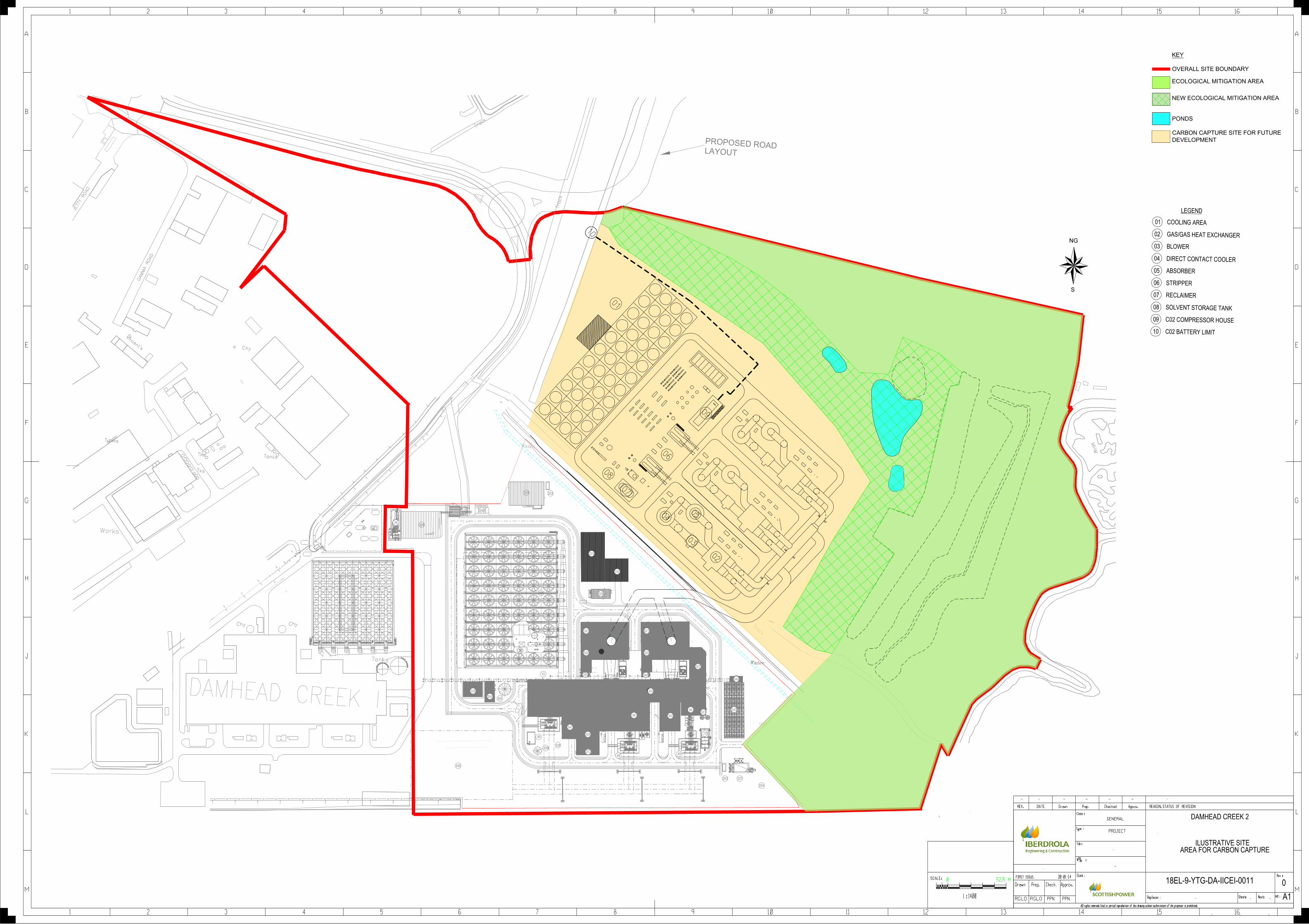
KEY
OVERALL SITE BOUNDARY
CARBON CAPTURE SITE FOR FUTURE
DEVELOPMENT
LEGEND
GAS/GAS HEAT EXCHANGER
BLOWER
DIRECT CONTACT COOLER
ABSORBER
STRIPPER
RECLAIMER
SOLVENT STORAGE TANK
C02 COMPRESSOR HOUSE
C02 BATTERY LIMIT
01
02
03
04
05
06
07
08
09
10
COOLING AREA
LAYOUT
PROPOSED ROAD
St
Tanks
Chy
GA
MM
A
RO
AD
Track
Trac
k
Vincent's
Tanks
Tks
Works
Track
Tks
MH
W
NG
S
1
A
2 3 4 5 6 7 8 9 10 11 12 13 14 15 16
B
C
D
E
F
G
H
J
K
L
M
1 2 3 4 5 6 7 8 9 10 11 12 13 14 15 16
A
B
C
D
E
F
G
H
J
K
L
M
- - - - -
--
-
-
--
GENERAL
SCALE:
REV.
SIZE :
Rev :
Type :
Drawn Prep.
Checked Approv.
Sheet: Next:
Nº :
DATE Drawn Prep. REASON. STATUS OF REVISION
FIRST ISSUE:
Check. Approv.
Class :
File :
Client :
All rights reserved. Total or partial reproduction of this drawing without authorization of the propietor is prohibited.
Replaces :PPN PPN
-
RGLO RGLO
- - - - - -
20-01-14
DAMHEAD CREEK 2
AREA FOR CARBON CAPTURE ILUSTRATIVE SITE
18EL-9-YTG-DA-IICEI-0011 0
A1
PROJECT
0
1 : 1400
52,5 M
07
08
06
09
02
0504
03
10
01
Chy
Tanks
Chy
DAMHEAD CREEK I
RA
MP
A D
E F
UE
L G
AS
74
52
53
AP
BP
RF
RC
64
63
71
50
36
+5.625
5 5
20
55
49
338306
49
312
347
305
205
30097
49
300
72
96323
343
203 327
301
300
96
30
325
304
331 203
39329
PARKING
346
326
FENCE
8383
85348 34815
319
349
82319
344
30
345
82
333
332
321
320
314
321
204
81
80
81
80
84
307
320
NEW ECOLOGICAL MITIGATION AREA
ECOLOGICAL MITIGATION AREA
PONDS