Embed Size (px)
Citation preview
DI-704
User Manual
RECYCLABLE
Printed in Taiwan
II
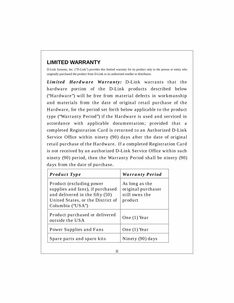
LIMITED WARRANTY D-Link Systems, Inc. (“D-Link”) provides this limited warranty for its product only to the person or entity who originally purchased the product from D-Link or its authorized reseller or distributor.
Limited Hardware Warranty: D-Link warrants that the hardware portion of the D-Link products described below (“Hardware”) will be free from material defects in workmanship and materials from the date of original retail purchase of the Hardware, for the period set forth below applicable to the product type (“Warranty Period”) if the Hardware is used and serviced in accordance with applicable documentation; provided that a completed Registration Card is returned to an Authorized D-Link Service Office within ninety (90) days after the date of original retail purchase of the Hardware. If a completed Registration Card is not received by an authorized D-Link Service Office within such ninety (90) period, then the Warranty Period shall be ninety (90) days from the date of purchase.
Product Type Warranty Period
Product (excluding power supplies and fans), if purchased and delivered in the fifty (50) United States, or the District of Columbia (“USA”)
As long as the original purchaser still owns the product
Product purchased or delivered outside the USA
One (1) Year
Power Supplies and Fans One (1) Year
Spare parts and spare kits Ninety (90) days
III
D-Link’s sole obligation shall be to repair or replace the defective Hardware at no charge to the original owner. Such repair or replacement will be rendered by D-Link at an Authorized D-Link Service Office. The replacement Hardware need not be new or of an identical make, model or part; D-Link may in its discretion may replace the defective Hardware (or any part thereof) with any reconditioned product that D-Link reasonably determines is substantially equivalent (or superior) in all material respects to the defective Hardware. The Warranty Period shall extend for an additional ninety (90) days after any repaired or replaced Hardware is delivered. If a material defect is incapable of correction, or if D-Link determines in its sole discretion that it is not practical to repair or replace the defective Hardware, the price paid by the original purchaser for the defective Hardware will be refunded by D-Link upon return to D-Link of the defective Hardware. All Hardware (or part thereof) that is replaced by D-Link, or for which the purchase price is refunded, shall become the property of D-Link upon replacement or refund. Limited Software Warranty: D-Link warrants that the software portion of the product (“Software”) will substantially conform to D-Link’s then current functional specifications for the Software, as set forth in the applicable documentation, from the date of original delivery of the Software for a period of ninety (90) days (“Warranty Period”), if the Software is properly installed on approved hardware and operated as contemplated in its documentation. D-Link further warrants that, during the Warranty Period, the magnetic media on which D-Link delivers the Software will be free of physical defects. D-Link’s sole obligation shall be to replace the non-conforming Software (or defective media) with software that substantially conforms to D-Link’s functional specifications for the Software. Except as otherwise agreed by D-Link in writing, the replacement Software is provided only to the original licensee, and is subject to the terms and conditions of the license granted by D-Link for the Software. The Warranty Period shall extend for an additional ninety (90) days after any replacement Software is delivered. If a material non-conformance is incapable of correction, or if D-Link determines in its sole discretion that it is not practical to replace the non-conforming Software, the price paid by the original licensee for the non-conforming Software will be refunded by D-Link; provided that the non-conforming Software (and all copies thereof) is first returned to D-Link. The license granted respecting any Software for which a refund is given automatically terminates. What You Must Do For Warranty Service: Registration Card. The Registration Card provided at the back of this manual must be completed and returned to an Authorized D-Link Service Office for each D-Link product within ninety (90) days after the product is purchased and/or licensed. The addresses/telephone/fax list of the nearest Authorized D-Link Service Office is provided in the back of this manual. FAILURE TO PROPERLY COMPLETE AND TIMELY RETURN THE REGISTRATION CARD MAY AFFECT THE WARRANTY FOR THIS PRODUCT. Submitting A Claim. Any claim under this limited warranty must be submitted in writing before the end of the Warranty Period to an Authorized D-Link Service Office. The claim must include a written description of the Hardware defect or Software nonconformance in sufficient detail to allow D-Link to confirm the same. The original product owner must obtain a Return Material Authorization (RMA) number from the Authorized D-Link Service Office and, if requested, provide written proof of purchase of the product (such as a copy of the dated purchase invoice for the product) before the warranty service is provided. After an RMA number is issued, the defective product must be packaged securely in the original or other suitable shipping package to ensure that it will not be damaged in transit, and the RMA number must be prominently marked on the outside of the package. The packaged product shall be insured and shipped to D-Link, 53 Discovery Drive, Irvine CA 92618, with all shipping costs prepaid. D-Link may reject or return any product that is not packaged and shipped in strict compliance with the
IV
foregoing requirements, or for which an RMA number is not visible from the outside of the package. The product owner agrees to pay D-Link’s reasonable handling and return shipping charges for any product that is not packaged and shipped in accordance with the foregoing requirements, or that is determined by D-Link not to be defective or non-conforming. What Is Not Covered: This limited warranty provided by D-Link does not cover: Products that have been subjected to abuse, accident, alteration, modification, tampering, negligence, misuse, faulty installation, lack of reasonable care, repair or service in any way that is not contemplated in the documentation for the product, or if the model or serial number has been altered, tampered with, defaced or removed; Initial installation, installation and removal of the product for repair, and shipping costs; Operational adjustments covered in the operating manual for the product, and normal maintenance; Damage that occurs in shipment, due to act of God, failures due to power surge, and cosmetic damage; and Any hardware, software, firmware or other products or services provided by anyone other than D-Link. Disclaimer of Other Warranties: EXCEPT FOR THE LIMITED WARRANTY SPECIFIED HEREIN, THE PRODUCT IS PROVIDED “AS-IS” WITHOUT ANY WARRANTY OF ANY KIND INCLUDING, WITHOUT LIMITATION, ANY WARRANTY OF MERCHANTABILITY, FITNESS FOR A PARTICULAR PURPOSE AND NON-INFRINGEMENT. IF ANY IMPLIED WARRANTY CANNOT BE DISCLAIMED IN ANY TERRITORY WHERE A PRODUCT IS SOLD, THE DURATION OF SUCH IMPLIED WARRANTY SHALL BE LIMITED TO NINETY (90) DAYS. EXCEPT AS EXPRESSLY COVERED UNDER THE LIMITED WARRANTY PROVIDED HEREIN, THE ENTIRE RISK AS TO THE QUALITY, SELECTION AND PERFORMANCE OF THE PRODUCT IS WITH THE PURCHASER OF THE PRODUCT. Limitation of Liability: TO THE MAXIMUM EXTENT PERMITTED BY LAW, D-LINK IS NOT LIABLE UNDER ANY CONTRACT, NEGLIGENCE, STRICT LIABILITY OR OTHER LEGAL OR EQUITABLE THEORY FOR ANY LOSS OF USE OF THE PRODUCT, INCONVENIENCE OR DAMAGES OF ANY CHARACTER, WHETHER DIRECT, SPECIAL, INCIDENTAL OR CONSEQUENTIAL (INCLUDING, BUT NOT LIMITED TO, DAMAGES FOR LOSS OF GOODWILL, WORK STOPPAGE, COMPUTER FAILURE OR MALFUNCTION, LOSS OF INFORMATION OR DATA CONTAINED IN, STORED ON, OR INTEGRATED WITH ANY PRODUCT RETURNED TO D-LINK FOR WARRANTY SERVICE) RESULTING FROM THE USE OF THE PRODUCT, RELATING TO WARRANTY SERVICE, OR ARISING OUT OF ANY BREACH OF THIS LIMITED WARRANTY, EVEN IF D-LINK HAS BEEN ADVISED OF THE POSSIBILITY OF SUCH DAMAGES. THE SOLE REMEDY FOR A BREACH OF THE FOREGOING LIMITED WARRANTY IS REPAIR, REPLACEMENT OR REFUND OF THE DEFECTIVE OR NON-CONFORMING PRODUCT. GOVERNING LAW: This Limited Warranty shall be governed by the laws of the state of California. Some states do not allow exclusion or limitation of incidental or consequential damages, or limitations on how long an implied warranty lasts, so the foregoing limitations and exclusions may not apply. This limited warranty provides specific legal rights and the product owner may also have other rights which vary from state to state.
Wichtige Sicherheitshinweise 1. Bitte lesen Sie sich diese Hinweise sorgfältig durch.
V
2. Heben Sie diese Anleitung für den spätern Gebrauch auf.
3. Vor jedem Reinigen ist das Gerät vom Stromnetz zu trennen. Vervenden Sie keine Flüssig- oder
Aerosolreiniger. Am besten dient ein angefeuchtetes Tuch zur Reinigung.
4. Um eine Beschädigung des Gerätes zu vermeiden sollten Sie nur Zubehörteile verwenden, die vom Hersteller
zugelassen sind.
5. Das Gerät is vor Feuchtigkeit zu schützen.
6. Bei der Aufstellung des Gerätes ist auf sichern Stand zu achten. Ein Kippen oder Fallen könnte Verletzungen
hervorrufen. Verwenden Sie nur sichere Standorte und beachten Sie die Aufstellhinweise des Herstellers.
7. Die Belüftungsöffnungen dienen zur Luftzirkulation die das Gerät vor Überhitzung schützt. Sorgen Sie dafür,
daß diese Öffnungen nicht abgedeckt werden.
8. Beachten Sie beim Anschluß an das Stromnetz die Anschlußwerte.
9. Die Netzanschlußsteckdose muß aus Gründen der elektrischen Sicherheit einen Schutzleiterkontakt haben.
10. Verlegen Sie die Netzanschlußleitung so, daß niemand darüber fallen kann. Es sollete auch nichts auf der
Leitung abgestellt werden.
11. Alle Hinweise und Warnungen die sich am Geräten befinden sind zu beachten.
12. Wird das Gerät über einen längeren Zeitraum nicht benutzt, sollten Sie es vom Stromnetz trennen. Somit
wird im Falle einer Überspannung eine Beschädigung vermieden.
13. Durch die Lüftungsöffnungen dürfen niemals Gegenstände oder Flüssigkeiten in das Gerät gelangen. Dies
könnte einen Brand bzw. Elektrischen Schlag auslösen.
14. Öffnen Sie niemals das Gerät. Das Gerät darf aus Gründen der elektrischen Sicherheit nur von
authorisiertem Servicepersonal geöffnet werden.
15. Wenn folgende Situationen auftreten ist das Gerät vom Stromnetz zu trennen und von einer qualifizierten
Servicestelle zu überprüfen:
a – Netzkabel oder Netzstecker sint beschädigt.
b – Flüssigkeit ist in das Gerät eingedrungen.
c – Das Gerät war Feuchtigkeit ausgesetzt.
d – Wenn das Gerät nicht der Bedienungsanleitung ensprechend funktioniert oder Sie mit Hilfe dieser
Anleitung keine Verbesserung erzielen.
e – Das Gerät ist gefallen und/oder das Gehäuse ist beschädigt.
f – Wenn das Gerät deutliche Anzeichen eines Defektes aufweist.
16. Bei Reparaturen dürfen nur Orginalersatzteile bzw. den Orginalteilen entsprechende Teile verwendet werden.
Der Einsatz von ungeeigneten Ersatzteilen kann eine weitere Beschädigung hervorrufen.
17. Wenden Sie sich mit allen Fragen die Service und Repartur betreffen an Ihren Servicepartner. Somit stellen
Sie die Betriebssicherheit des Gerätes sicher.
18. Zum Netzanschluß dieses Gerätes ist eine geprüfte Leitung zu verwenden, Für einen Nennstrom bis 6A und
einem Gerätegewicht gr ßer 3kg ist eine Leitung nicht leichter als H05VV-F, 3G, 0.75mm2 einzusetzen.
Trademarks Copyright 1999 D-Link Corporation. Contents subject to change without prior notice. D-Link is a registered trademark of D-Link Corporation/D-Link Systems, Inc. All other trademarks belong to their respective proprietors.
VI
Copyright Statement No part of this publication may be reproduced in any form or by any means or used to make any derivative such as translation, transformation, or adaptation without permission from D-Link Corporation/D-Link Systems Inc., as stipulated by the United States Copyright Act of 1976.
CE Mark Warning This is a Class B product. In a domestic environment, this product may cause radio interference, in which case the user may be required to take adequate measures Warnung! Dies ist in Produkt der Klasse B. Im Wohnbereich kann dieses Produkt Funkstoerungen verursachen. In diesem Fall kann vom Benutzer verlangt werden, angemessene Massnahmen zu ergreifen. Advertencia de Marca de la CE Este es un producto de Clase B. En un entorno doméstico, puede causar interferencias de radio, en cuyo case, puede requerirse al usuario para que adopte las medidas adecuadas. Attention! Ceci est un produit de classe B. Dans un environnement domestique, ce produit pourrait causer des interférences radio, auquel cas l`utilisateur devrait prendre les mesures adéquates. Attenzione! Il presente prodotto appartiene alla classe B. Se utilizzato in ambiente domestico il prodotto può causare interferenze radio, nel cui caso è possibile che l`utente debba assumere provvedimenti adeguati.
FCC Warning This equipment has been tested and found to comply with the limits for a Class B digital device, pursuant to part 15 of the FCC Rules. These limits are designed to provide reasonable protection against harmful interference in a residential installation. This equipment generates, uses and can radiate radio frequency energy and, if not installed and used in accordance with the instructions, may cause harmful interference to radio communications. However, there is no guarantee that interference will not occur in a particular installation. If this equipment does cause harmful interference to radio or television reception, which can be determined by turning the equipment off and on, the user is encouraged to try to correct the interference by one or more of the following measures: -Reorient or relocate the receiving antenna. -Increase the separation between the equipment and receiver.

VII
-Connect the equipment into an outlet on a circuit different from that to which the receiver is connected.
-Consult the dealer or an experienced radio/ TV technician for help. VCCI Warning
VIII
Table of Contents Chapter 1 Introduction.................................................................................. 1
1.1 Functions and Features .................................................................... 1 1.2 Packing List ..................................................................................... 2
Chapter 2 Hardware Installation................................................................... 3 2.1 Panel Layout.................................................................................... 3 2.2 Installation Requirements................................................................ 4 2.3 Procedure for Hardware Installation ............................................... 5
Chapter 3 Network Settings ......................................................................... 6 Chapter 4 Configuring The DI-704 .............................................................. 8
4.1 Start-up and Log in .......................................................................... 8 4.2 Status ............................................................................................... 9 4.3 Tools .............................................................................................. 10 4.4 Setup.............................................................................................. 11 4.5 DHCP Server ................................................................................. 13 4.6 Virtual Server................................................................................. 14 4.7 Special AP ..................................................................................... 15 4.8 Access Control............................................................................... 16 4.9 Misc Items ..................................................................................... 17
Appendix A Console Mode ........................................................................ 18 Appendix B TCP/IP Configuration for Windows 95/98 ............................. 19
B.1 Install TCP/IP Protocol into Your PC ........................................... 19 B.2 Set TCP/IP Protocol for Working with the DI-704....................... 20
Appendix C Technical Specifications.......................................................... 28
1
Chapter 1 Introduction
Congratulations on your purchase of the DI-704 Broadband Router. The DI-704 is
specifically designed for Small Office and Home Office needs. It provides a complete
solution for Internet surfing and office resource sharing, and is easy for non-technical users
to configure and operate. Instructions for installing and configuring the DI-704 can be found
in this manual. Before you install and use the DI-704, please read this manual carefully to
fully understand the functions of the DI-704.
1.1 Functions and Features
! Broadband modem and IP sharing
Connects multiple computers to a broadband (cable or DSL) modem or an
Ethernet router to surf the Internet.
! Auto-sensing Ethernet Switch
Equipped with a 4-port 10/100Mb auto-sensing Ethernet switch.
! VPN supported
Supports multiple PPTP sessions and allows setup of a VPN server and VPN
clients.
! Firewall
All unwanted packets from outside intruders are blocked to protect your Intranet.
! DHCP server supported
All of the networked computers can retrieve TCP/IP settings automatically from
the DI-704.
! Web-based configuring
Configurable through any networked computer’s web browser using Netscape or
Internet Explorer.
! Access Control supported
2
Allows you to assign different access rights for different users.
! Virtual Server supported
Enables you to expose WWW, FTP and other services on your LAN to be
accessible to Internet users outside of your LAN.
! User-Definable Application Sensing Tunnel
User can define the attributes to support the special applications requiring multiple
connections, like Internet gaming, video conferencing, Internet telephony and so
on, then the DI-704 can sense the application type and open a multi-port tunnel for
it.
! DMZ Host supported
DMZ Host fully exposes a networked computer to the Internet. Use this feature
when the special application sensing tunnel feature does not allow an application
to function properly.
1.2 Packing List
! One DI-704 broadband router unit
! One power cord
! User Manual
! Quick Installation Guide
! Two CAT-5 UTP Fast Ethernet cables
3
Chapter 2 Hardware Installation
2.1 Panel Layout
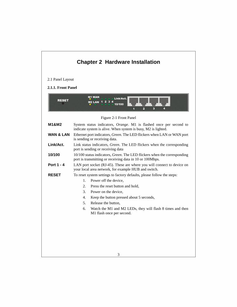
2.1.1. Front Panel
Figure 2-1 Front Panel
M1&M2 System status indicators, Orange. M1 is flashed once per second to indicate system is alive. When system is busy, M2 is lighted.
WAN & LAN Ethernet port indicators, Green. The LED flickers when LAN or WAN port is sending or receiving data.
Link/Act. Link status indicators, Green. The LED flickers when the corresponding port is sending or receiving data
10/100 10/100 status indicators, Green. The LED flickers when the corresponding port is transmitting or receiving data in 10 or 100Mbps.
Port 1 - 4 LAN port socket (RJ-45). These are where you will connect to device on your local area network, for example HUB and switch.
RESET To reset system settings to factory defaults, please follow the steps: 1. Power off the device, 2. Press the reset button and hold, 3. Power on the device, 4. Keep the button pressed about 5 seconds, 5. Release the button, 6. Watch the M1 and M2 LEDs, they will flash 8 times and then
M1 flash once per second.
4
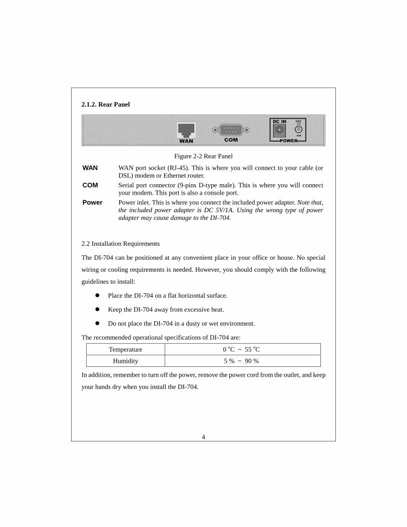
2.1.2. Rear Panel
Figure 2-2 Rear Panel
WAN WAN port socket (RJ-45). This is where you will connect to your cable (or DSL) modem or Ethernet router.
COM Serial port connector (9-pins D-type male). This is where you will connect your modem. This port is also a console port.
Power Power inlet. This is where you connect the included power adapter. Note that, the included power adapter is DC 5V/1A. Using the wrong type of power adapter may cause damage to the DI-704.
2.2 Installation Requirements
The DI-704 can be positioned at any convenient place in your office or house. No special
wiring or cooling requirements is needed. However, you should comply with the following
guidelines to install:
! Place the DI-704 on a flat horizontal surface.
! Keep the DI-704 away from excessive heat.
! Do not place the DI-704 in a dusty or wet environment.
The recommended operational specifications of DI-704 are:
Temperature 0 oC ~ 55 oC
Humidity 5 % ~ 90 %
In addition, remember to turn off the power, remove the power cord from the outlet, and keep
your hands dry when you install the DI-704.
5
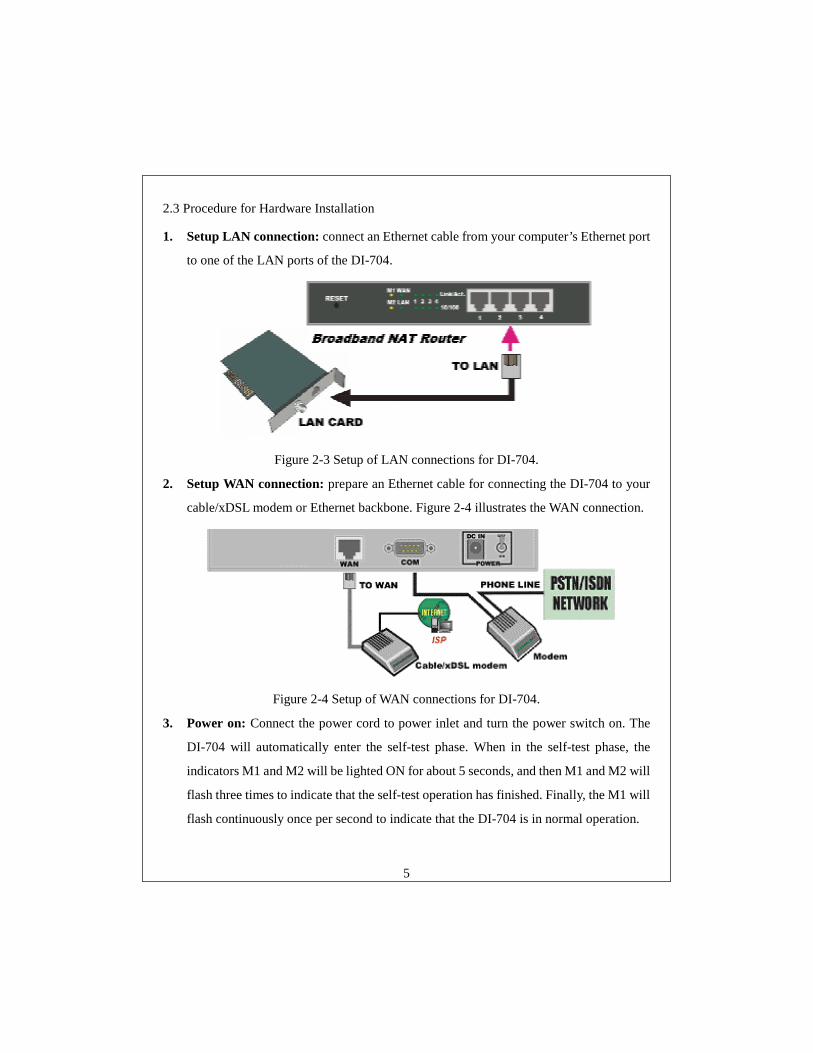
2.3 Procedure for Hardware Installation
1. Setup LAN connection: connect an Ethernet cable from your computer’s Ethernet port
to one of the LAN ports of the DI-704.
Figure 2-3 Setup of LAN connections for DI-704.
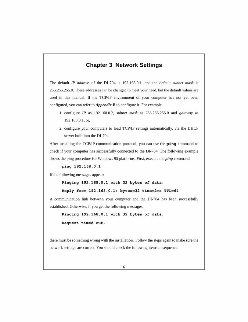
2. Setup WAN connection: prepare an Ethernet cable for connecting the DI-704 to your
cable/xDSL modem or Ethernet backbone. Figure 2-4 illustrates the WAN connection.
Figure 2-4 Setup of WAN connections for DI-704.
3. Power on: Connect the power cord to power inlet and turn the power switch on. The
DI-704 will automatically enter the self-test phase. When in the self-test phase, the
indicators M1 and M2 will be lighted ON for about 5 seconds, and then M1 and M2 will
flash three times to indicate that the self-test operation has finished. Finally, the M1 will
flash continuously once per second to indicate that the DI-704 is in normal operation.
6
Chapter 3 Network Settings
The default IP address of the DI-704 is 192.168.0.1, and the default subnet mask is
255.255.255.0. These addresses can be changed to meet your need, but the default values are
used in this manual. If the TCP/IP environment of your computer has not yet been
configured, you can refer to Appendix B to configure it. For example,
1. configure IP as 192.168.0.2, subnet mask as 255.255.255.0 and gateway as
192.168.0.1, or,
2. configure your computers to load TCP/IP settings automatically, via the DHCP
server built into the DI-704.
After installing the TCP/IP communication protocol, you can use the ping command to
check if your computer has successfully connected to the DI-704. The following example
shows the ping procedure for Windows 95 platforms. First, execute the ping command
ping 192.168.0.1
If the following messages appear:
Pinging 192.168.0.1 with 32 bytes of data:
Reply from 192.168.0.1: bytes=32 time=2ms TTL=64
A communication link between your computer and the DI-704 has been successfully
established. Otherwise, if you get the following messages,
Pinging 192.168.0.1 with 32 bytes of data:
Request timed out.
there must be something wrong with the installation. Follow the steps again to make sure the
network settings are correct. You should check the following items in sequence:
7
1. Is the Ethernet cable correctly connected between the DI-704 and your computer?
Tip: The LAN LED of the DI-704 and the link LED of network card on your computer
must be lighted.
2. Is the TCP/IP environment of your computers properly configured?
Tip: If the IP address of the DI-704 is 192.168.0.1, the IP address of your computer
must be 192.168.0.X and default gateway must be 192.168.0.1.
8
Chapter 4 Configuring The DI-704
The DI-704 provides a Web based configuration scheme, that is, configuring by Netscape
Communicator or Internet Explorer. This approach can be adopted in any MS Windows,
Macintosh or UNIX based platform.
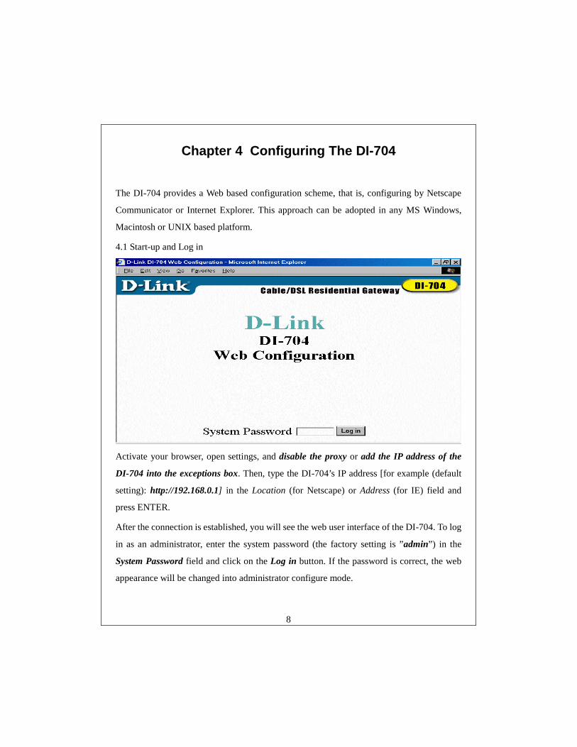
4.1 Start-up and Log in
Activate your browser, open settings, and disable the proxy or add the IP address of the
DI-704 into the exceptions box. Then, type the DI-704’s IP address [for example (default
setting): http://192.168.0.1] in the Location (for Netscape) or Address (for IE) field and
press ENTER.
After the connection is established, you will see the web user interface of the DI-704. To log
in as an administrator, enter the system password (the factory setting is ”admin”) in the
System Password field and click on the Log in button. If the password is correct, the web
appearance will be changed into administrator configure mode.
9
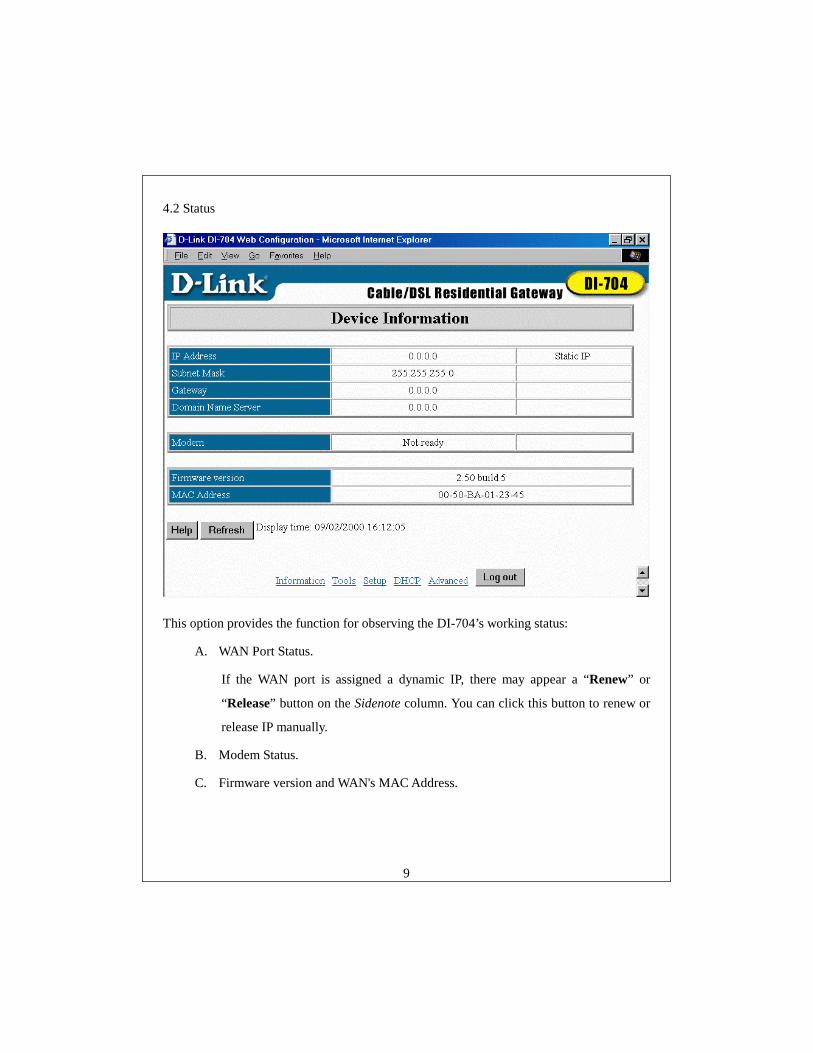
4.2 Status
This option provides the function for observing the DI-704’s working status:
A. WAN Port Status.
If the WAN port is assigned a dynamic IP, there may appear a “Renew” or
“Release” button on the Sidenote column. You can click this button to renew or
release IP manually.
B. Modem Status.
C. Firmware version and WAN's MAC Address.
10
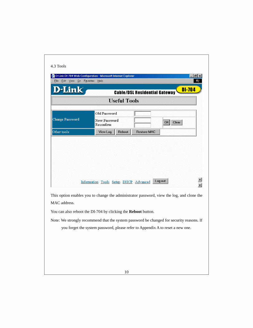
4.3 Tools
This option enables you to change the administrator password, view the log, and clone the
MAC address.
You can also reboot the DI-704 by clicking the Reboot button.
Note: We strongly recommend that the system password be changed for security reasons. If
you forget the system password, please refer to Appendix A to reset a new one.
11
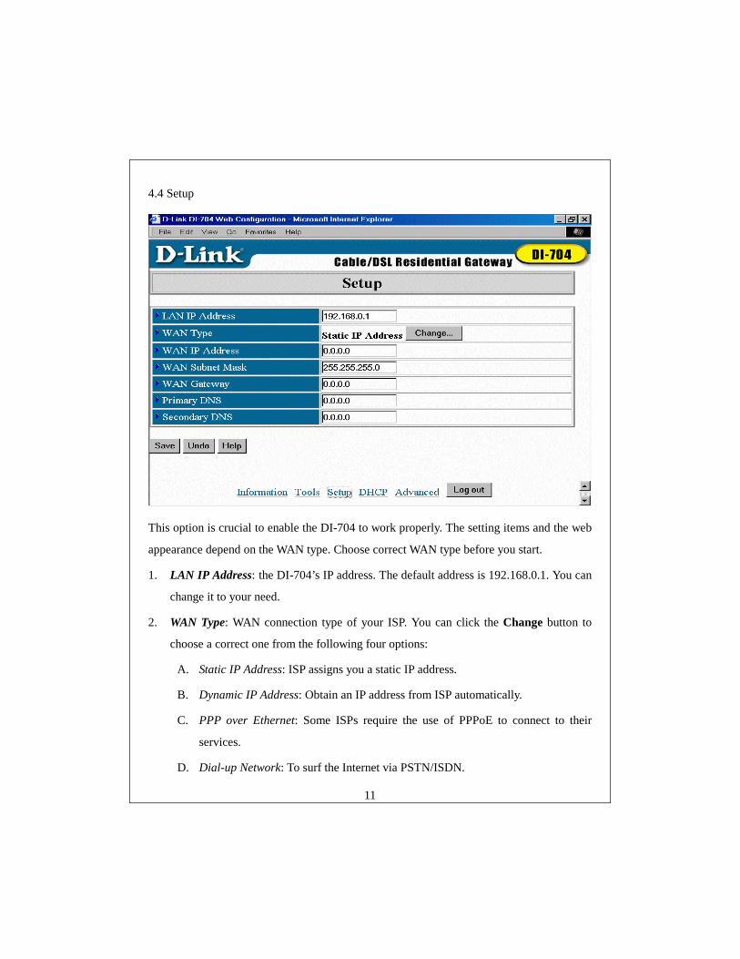
4.4 Setup
This option is crucial to enable the DI-704 to work properly. The setting items and the web
appearance depend on the WAN type. Choose correct WAN type before you start.
1. LAN IP Address: the DI-704’s IP address. The default address is 192.168.0.1. You can
change it to your need.
2. WAN Type: WAN connection type of your ISP. You can click the Change button to
choose a correct one from the following four options:
A. Static IP Address: ISP assigns you a static IP address.
B. Dynamic IP Address: Obtain an IP address from ISP automatically.
C. PPP over Ethernet: Some ISPs require the use of PPPoE to connect to their
services.
D. Dial-up Network: To surf the Internet via PSTN/ISDN.
12
4.4.1 Static IP Address
WAN IP Address, Subnet Mask, Gateway, Primary and Secondary DNS: enter the proper
setting value provided by your ISP.
4.4.2 Dynamic IP Address
1. Host Name: optional. Required by some ISPs, for example, @Home.
2. Renew IP Forever: this feature enables the DI-704 to renew its IP address
automatically when the lease time is expired even if the system is idle.
4.4.3 PPP over Ethernet
1. PPPoE Account and Password: the account and password your ISP assigned to you. If
you don't want to change the password, keep it empty.
2. PPPoE Service Name: optional. Input the service name if your ISP requires it.
3. Maximum Idle Time: the maximum time the connection is idle before you are
disconnected from your ISP and your PPPoE session is terminated.
4.4.4 Dial-up Network
1. Dial-up Telephone, Account and Password: assigned by your ISP. If you don't want to
change the password, keep it empty.
2. Primary and Secondary DNS: automatically assigned if they are configured as
"0.0.0.0."
3. Maximum Idle Time: the time of no activity before you are automatically disconnected
from your dial-up session.
4. Baud Rate: the communication speed between the DI-704 and your MODEM or ISDN
TA.
5. Extra Setting: optional settings to optimize the communication quality between the ISP
and your MODEM or ISDN TA. Use if your ISP recommends and provides these
settings.
13
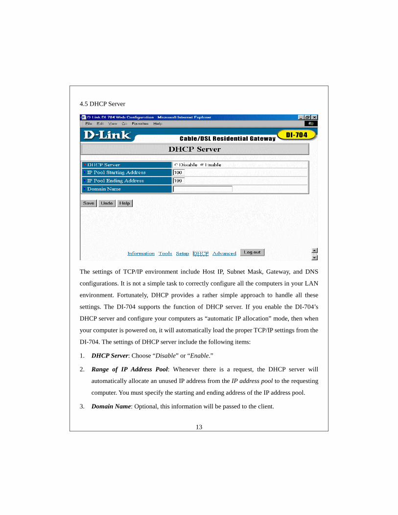
4.5 DHCP Server
The settings of TCP/IP environment include Host IP, Subnet Mask, Gateway, and DNS
configurations. It is not a simple task to correctly configure all the computers in your LAN
environment. Fortunately, DHCP provides a rather simple approach to handle all these
settings. The DI-704 supports the function of DHCP server. If you enable the DI-704’s
DHCP server and configure your computers as “automatic IP allocation” mode, then when
your computer is powered on, it will automatically load the proper TCP/IP settings from the
DI-704. The settings of DHCP server include the following items:
1. DHCP Server: Choose “Disable” or “Enable.”
2. Range of IP Address Pool: Whenever there is a request, the DHCP server will
automatically allocate an unused IP address from the IP address pool to the requesting
computer. You must specify the starting and ending address of the IP address pool.
3. Domain Name: Optional, this information will be passed to the client.
14
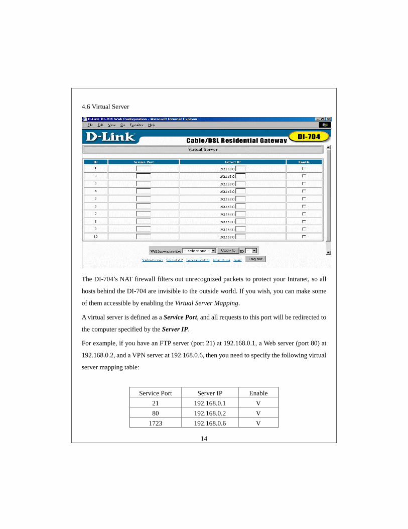
4.6 Virtual Server
The DI-704’s NAT firewall filters out unrecognized packets to protect your Intranet, so all
hosts behind the DI-704 are invisible to the outside world. If you wish, you can make some
of them accessible by enabling the Virtual Server Mapping.
A virtual server is defined as a Service Port, and all requests to this port will be redirected to
the computer specified by the Server IP.
For example, if you have an FTP server (port 21) at 192.168.0.1, a Web server (port 80) at
192.168.0.2, and a VPN server at 192.168.0.6, then you need to specify the following virtual
server mapping table:
Service Port Server IP Enable 21 192.168.0.1 V 80 192.168.0.2 V
1723 192.168.0.6 V
15
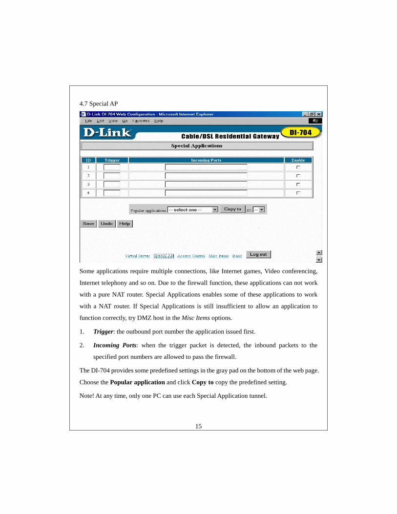
4.7 Special AP
Some applications require multiple connections, like Internet games, Video conferencing,
Internet telephony and so on. Due to the firewall function, these applications can not work
with a pure NAT router. Special Applications enables some of these applications to work
with a NAT router. If Special Applications is still insufficient to allow an application to
function correctly, try DMZ host in the Misc Items options.
1. Trigger: the outbound port number the application issued first.
2. Incoming Ports: when the trigger packet is detected, the inbound packets to the
specified port numbers are allowed to pass the firewall.
The DI-704 provides some predefined settings in the gray pad on the bottom of the web page.
Choose the Popular application and click Copy to copy the predefined setting.
Note! At any time, only one PC can use each Special Application tunnel.
16
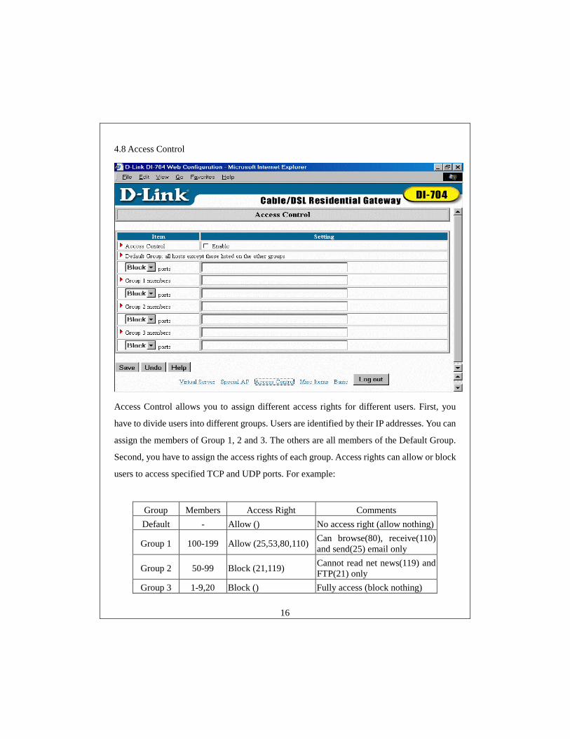
4.8 Access Control
Access Control allows you to assign different access rights for different users. First, you
have to divide users into different groups. Users are identified by their IP addresses. You can
assign the members of Group 1, 2 and 3. The others are all members of the Default Group.
Second, you have to assign the access rights of each group. Access rights can allow or block
users to access specified TCP and UDP ports. For example:
Group Members Access Right Comments Default - Allow () No access right (allow nothing)
Group 1 100-199 Allow (25,53,80,110) Can browse(80), receive(110) and send(25) email only
Group 2 50-99 Block (21,119) Cannot read net news(119) and FTP(21) only
Group 3 1-9,20 Block () Fully access (block nothing)
17
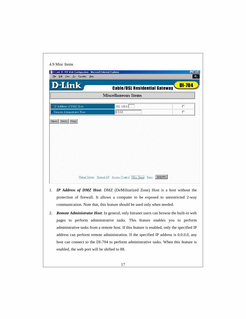
4.9 Misc Items
1. IP Address of DMZ Host: DMZ (DeMilitarized Zone) Host is a host without the
protection of firewall. It allows a computer to be exposed to unrestricted 2-way
communication. Note that, this feature should be used only when needed.
2. Remote Administrator Host: In general, only Intranet users can browse the built-in web
pages to perform administrative tasks. This feature enables you to perform
administrative tasks from a remote host. If this feature is enabled, only the specified IP
address can perform remote administration. If the specified IP address is 0.0.0.0, any
host can connect to the DI-704 to perform administrative tasks. When this feature is
enabled, the web port will be shifted to 88.
18
Appendix A Console Mode
When you forget the system password or the IP address of the DI-704, you need to enter
console mode to reset them.
Before invoking the console program, be sure to find a null modem cable and use it to
connect from the DI-704’s COM port to your computer’s COM port. Then, execute a
terminal program, such as the Hyper Terminal of MS Windows 95. The connection
parameters should be set to 19200 8-N-1. And, reboot the DI-704. When the M1 indicator
starts flashing regularly, you can press the “Enter” key of the keyboard several times, there
should be some messages and console prompt ">" appears in the terminal.
In the console mode, you may reset the IP address and the system password of the DI-704.
Please remember to execute the SR command to save the changes you have made. For
example,
IP 192.168.0.1
PW admin
SR
19
Appendix B TCP/IP Configuration for Windows 95/98
This section describes installing the TCP/IP protocol into your personal computer.
Supposing you have successfully installed one network card on your personal computer. If
not, please refer to your network card manual. Moreover, the Section B.2 tells you how to set
TCP/IP values for working with the DI-704 correctly.
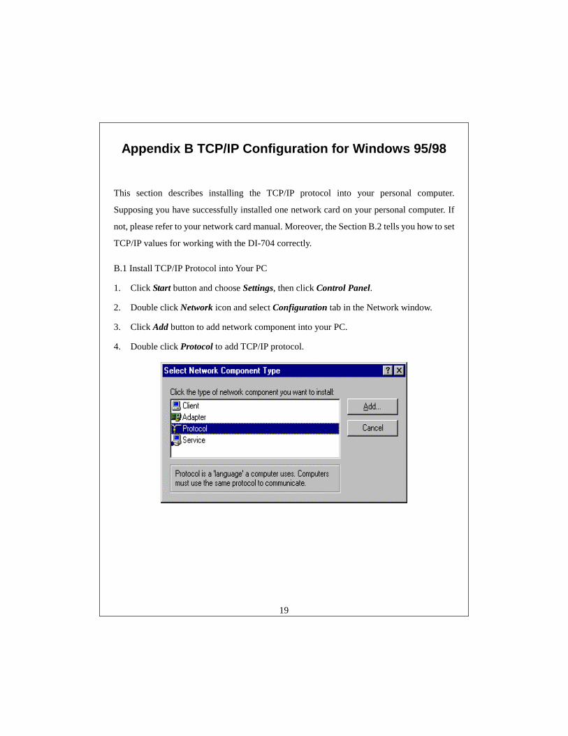
B.1 Install TCP/IP Protocol into Your PC
1. Click Start button and choose Settings, then click Control Panel.
2. Double click Network icon and select Configuration tab in the Network window.
3. Click Add button to add network component into your PC.
4. Double click Protocol to add TCP/IP protocol.
20
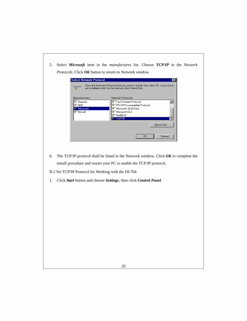
5. Select Microsoft item in the manufactures list. Choose TCP/IP in the Network
Protocols. Click OK button to return to Network window.
6. The TCP/IP protocol shall be listed in the Network window. Click OK to complete the
install procedure and restart your PC to enable the TCP/IP protocol.
B.2 Set TCP/IP Protocol for Working with the DI-704
1. Click Start button and choose Settings, then click Control Panel.
21
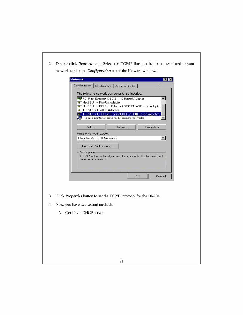
2. Double click Network icon. Select the TCP/IP line that has been associated to your
network card in the Configuration tab of the Network window.
3. Click Properties button to set the TCP/IP protocol for the DI-704.
4. Now, you have two setting methods:
A. Get IP via DHCP server
22
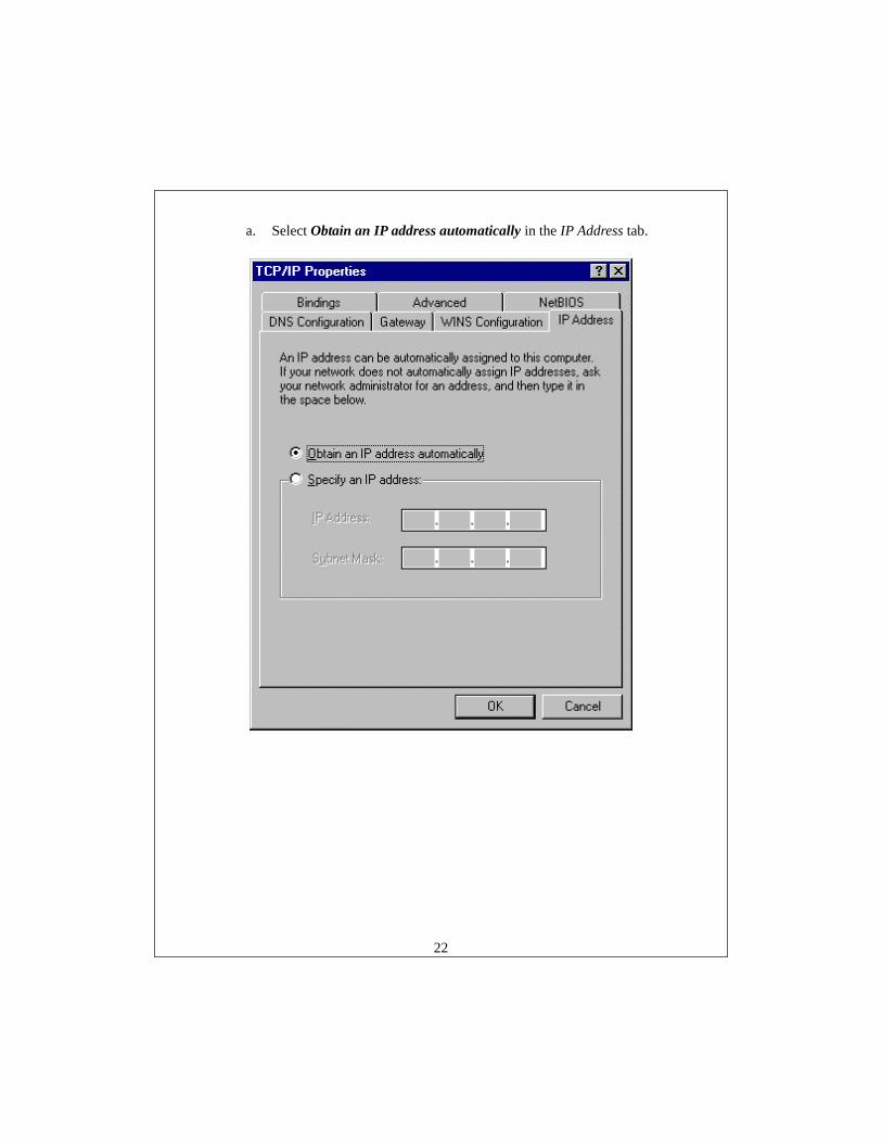
a. Select Obtain an IP address automatically in the IP Address tab.
23
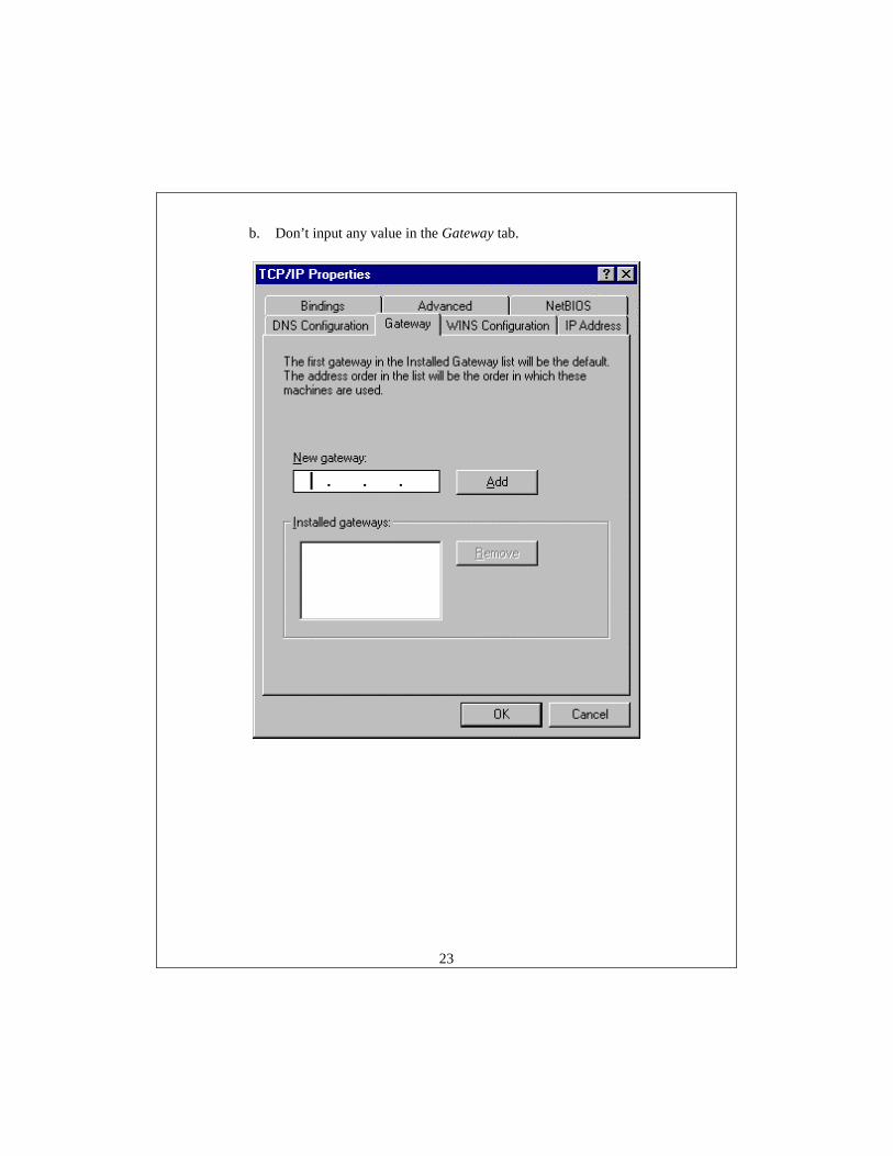
b. Don’t input any value in the Gateway tab.

24
c. Choose Disable DNS in the DNS Configuration tab.
25
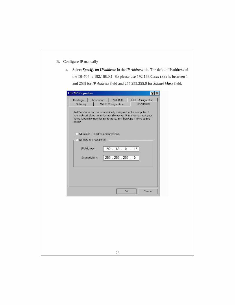
B. Configure IP manually
a. Select Specify an IP address in the IP Address tab. The default IP address of
the DI-704 is 192.168.0.1. So please use 192.168.0.xxx (xxx is between 1
and 253) for IP Address field and 255.255.255.0 for Subnet Mask field.

26
b. In the Gateway tab, add the IP address of the DI-704 (default IP is
192.168.0.1) in the New gateway field and click Add button.
27
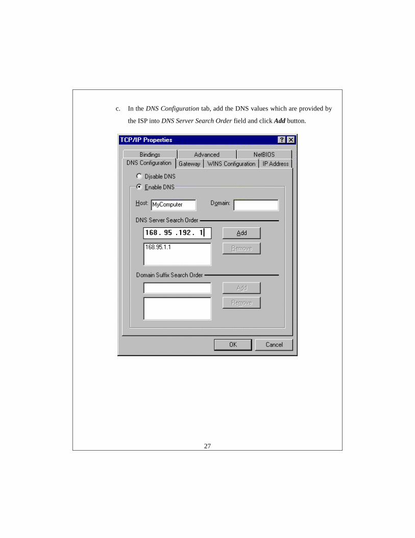
c. In the DNS Configuration tab, add the DNS values which are provided by
the ISP into DNS Server Search Order field and click Add button.
28
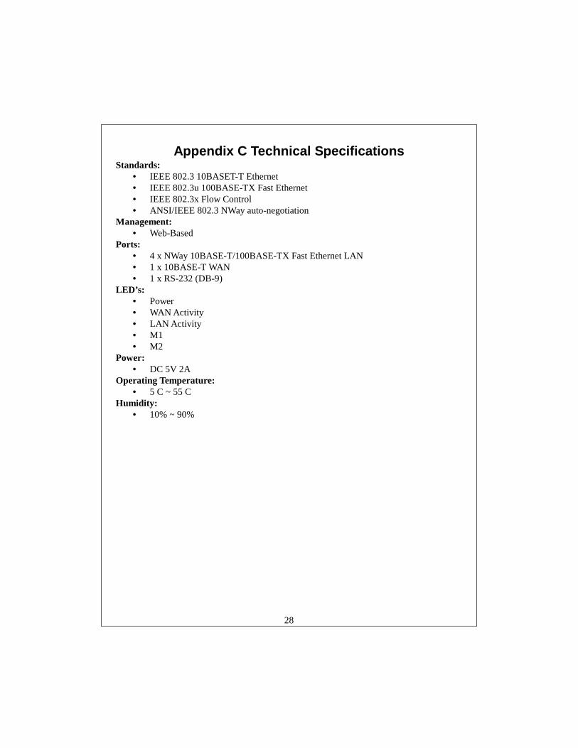
Appendix C Technical Specifications Standards:
• IEEE 802.3 10BASET-T Ethernet • IEEE 802.3u 100BASE-TX Fast Ethernet • IEEE 802.3x Flow Control • ANSI/IEEE 802.3 NWay auto-negotiation
Management: • Web-Based
Ports: • 4 x NWay 10BASE-T/100BASE-TX Fast Ethernet LAN • 1 x 10BASE-T WAN • 1 x RS-232 (DB-9)
LED’s: • Power • WAN Activity • LAN Activity • M1 • M2
Power: • DC 5V 2A
Operating Temperature: • 5 C ~ 55 C
Humidity: • 10% ~ 90%
29
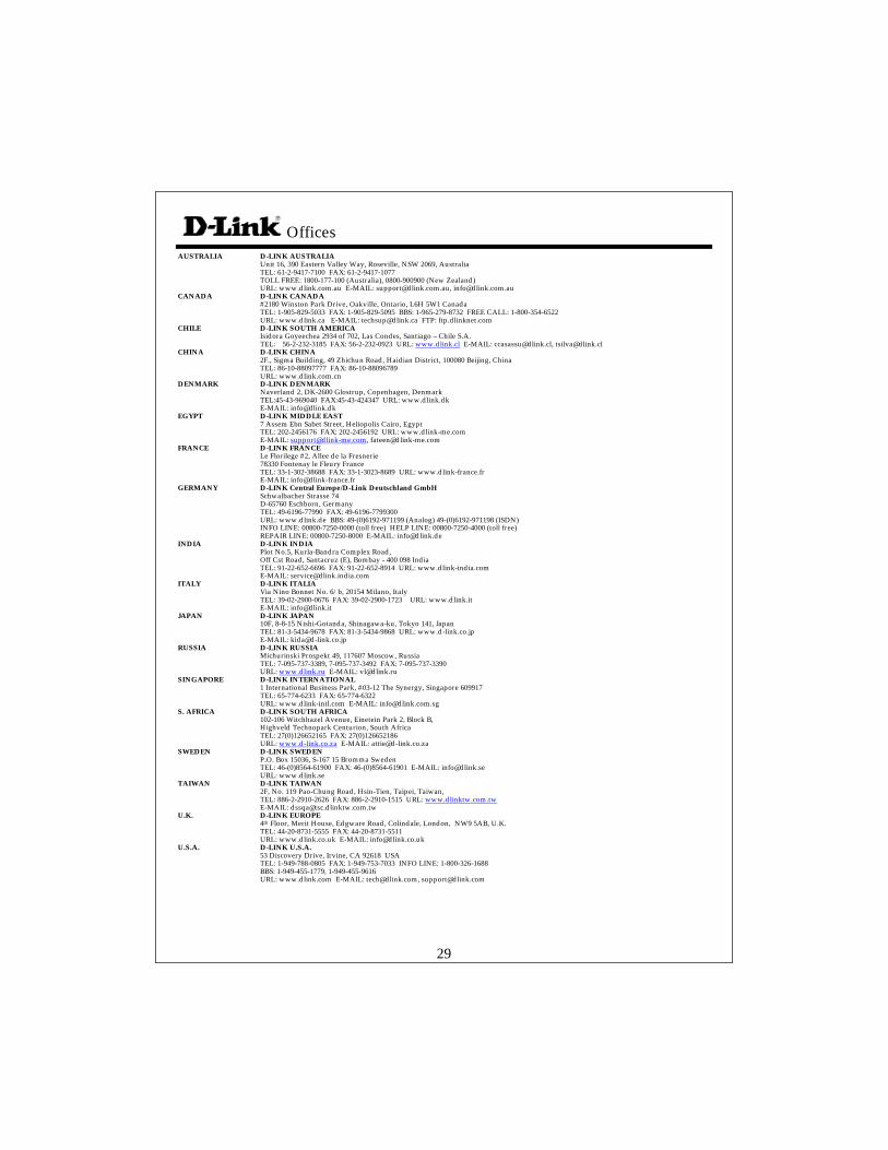
Offices AUSTRALIA D-LINK AUSTRALIA Unit 16, 390 Eastern Valley Way, Roseville, NSW 2069, Australia TEL: 61-2-9417-7100 FAX: 61-2-9417-1077 TOLL FREE: 1800-177-100 (Australia), 0800-900900 (New Zealand) URL: www.dlink.com.au E-MAIL: [email protected], [email protected] CANADA D-LINK CANADA #2180 Winston Park Drive, Oakville, Ontario, L6H 5W1 Canada TEL: 1-905-829-5033 FAX: 1-905-829-5095 BBS: 1-965-279-8732 FREE CALL: 1-800-354-6522 URL: www.dlink.ca E-MAIL: [email protected] FTP: ftp.dlinknet.com CHILE D-LINK SOUTH AMERICA Isidora Goyeechea 2934 of 702, Las Condes, Santiago – Chile S.A. TEL: 56-2-232-3185 FAX: 56-2-232-0923 URL: www.dlink.cl E-MAIL: [email protected], [email protected] CHINA D-LINK CHINA 2F., Sigma Building, 49 Zhichun Road, Haidian District, 100080 Beijing, China TEL: 86-10-88097777 FAX: 86-10-88096789 URL: www.dlink.com.cn DENMARK D-LINK DENMARK Naverland 2, DK-2600 Glostrup, Copenhagen, Denmark TEL:45-43-969040 FAX:45-43-424347 URL: www.dlink.dk E-MAIL: [email protected] EGYPT D-LINK MIDDLE EAST 7 Assem Ebn Sabet Street, Heliopolis Cairo, Egypt TEL: 202-2456176 FAX: 202-2456192 URL: www.dlink-me.com E-MAIL: [email protected], [email protected] FRANCE D-LINK FRANCE Le Florilege #2, Allee de la Fresnerie 78330 Fontenay le Fleury France TEL: 33-1-302-38688 FAX: 33-1-3023-8689 URL: www.dlink-france.fr E-MAIL: [email protected] GERMANY D-LINK Central Europe/D-Link Deutschland GmbH Schwalbacher Strasse 74 D-65760 Eschborn, Germany TEL: 49-6196-77990 FAX: 49-6196-7799300 URL: www.dlink.de BBS: 49-(0)6192-971199 (Analog) 49-(0)6192-971198 (ISDN) INFO LINE: 00800-7250-0000 (toll free) HELP LINE: 00800-7250-4000 (toll free) REPAIR LINE: 00800-7250-8000 E-MAIL: [email protected] INDIA D-LINK INDIA Plot No.5, Kurla-Bandra Complex Road, Off Cst Road, Santacruz (E), Bombay - 400 098 India TEL: 91-22-652-6696 FAX: 91-22-652-8914 URL: www.dlink-india.com E-MAIL: [email protected] ITALY D-LINK ITALIA Via Nino Bonnet No. 6/b, 20154 Milano, Italy TEL: 39-02-2900-0676 FAX: 39-02-2900-1723 URL: www.dlink.it E-MAIL: [email protected] JAPAN D-LINK JAPAN 10F, 8-8-15 Nishi-Gotanda, Shinagawa-ku, Tokyo 141, Japan TEL: 81-3-5434-9678 FAX: 81-3-5434-9868 URL: www.d-link.co.jp E-MAIL: [email protected] RUSSIA D-LINK RUSSIA Michurinski Prospekt 49, 117607 Moscow, Russia TEL: 7-095-737-3389, 7-095-737-3492 FAX: 7-095-737-3390 URL: www.dlink.ru E-MAIL: [email protected] SINGAPORE D-LINK INTERNATIONAL 1 International Business Park, #03-12 The Synergy, Singapore 609917 TEL: 65-774-6233 FAX: 65-774-6322 URL: www.dlink-intl.com E-MAIL: [email protected] S. AFRICA D-LINK SOUTH AFRICA 102-106 Witchhazel Avenue, Einetein Park 2, Block B, Highveld Technopark Centurion, South Africa TEL: 27(0)126652165 FAX: 27(0)126652186 URL: www.d-link.co.za E-MAIL: [email protected] SWEDEN D-LINK SWEDEN P.O. Box 15036, S-167 15 Bromma Sweden TEL: 46-(0)8564-61900 FAX: 46-(0)8564-61901 E-MAIL: [email protected] URL: www.dlink.se TAIWAN D-LINK TAIWAN 2F, No. 119 Pao-Chung Road, Hsin-Tien, Taipei, Taiwan, TEL: 886-2-2910-2626 FAX: 886-2-2910-1515 URL: www.dlinktw.com.tw E-MAIL: [email protected] U.K. D-LINK EUROPE 4th Floor, Merit House, Edgware Road, Colindale, London, NW9 5AB, U.K. TEL: 44-20-8731-5555 FAX: 44-20-8731-5511 URL: www.dlink.co.uk E-MAIL: [email protected] U.S.A. D-LINK U.S.A. 53 Discovery Drive, Irvine, CA 92618 USA TEL: 1-949-788-0805 FAX: 1-949-753-7033 INFO LINE: 1-800-326-1688 BBS: 1-949-455-1779, 1-949-455-9616 URL: www.dlink.com E-MAIL: [email protected], [email protected]
30
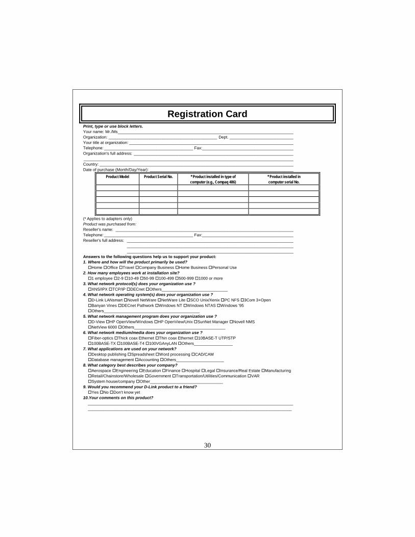
Registration Card Print, type or use block letters. Your name: Mr./Ms _____________________________________________________________________________ Organization: ________________________________________________ Dept. ____________________________ Your title at organization: ________________________________________________________________________ Telephone: _______________________________________ Fax:________________________________________ Organization's full address: ______________________________________________________________________ ____________________________________________________________________________________________ Country: _____________________________________________________________________________________ Date of purchase (Month/Day/Year): _______________________________________________________________
Product Model Product Serial No. * Product installed in type of computer (e.g., Compaq 486)
* Product installed in computer serial No.
(* Applies to adapters only) Product was purchased from: Reseller's name: ______________________________________________________________________________ Telephone: _______________________________________ Fax:________________________________________ Reseller's full address: _________________________________________________________________________ _________________________________________________________________________ _________________________________________________________________________ Answers to the following questions help us to support your product: 1. Where and how will the product primarily be used? #Home #Office #Travel #Company Business #Home Business #Personal Use 2. How many employees work at installation site? #1 employee #2-9 #10-49 #50-99 #100-499 #500-999 #1000 or more 3. What network protocol(s) does your organization use ? #XNS/IPX #TCP/IP #DECnet #Others_____________________________ 4. What network operating system(s) does your organization use ? #D-Link LANsmart #Novell NetWare #NetWare Lite #SCO Unix/Xenix #PC NFS #3Com 3+Open #Banyan Vines #DECnet Pathwork #Windows NT #Windows NTAS #Windows '95 #Others__________________________________________ 5. What network management program does your organization use ? #D-View #HP OpenView/Windows #HP OpenView/Unix #SunNet Manager #Novell NMS #NetView 6000 #Others________________________________________ 6. What network medium/media does your organization use ? #Fiber-optics #Thick coax Ethernet #Thin coax Ethernet #10BASE-T UTP/STP #100BASE-TX #100BASE-T4 #100VGAnyLAN #Others_________________ 7. What applications are used on your network? #Desktop publishing #Spreadsheet #Word processing #CAD/CAM #Database management #Accounting #Others_____________________ 8. What category best describes your company? #Aerospace #Engineering #Education #Finance #Hospital #Legal #Insurance/Real Estate #Manufacturing #Retail/Chainstore/Wholesale #Government #Transportation/Utilities/Communication #VAR #System house/company #Other________________________________ 9. Would you recommend your D-Link product to a friend? #Yes #No #Don't know yet 10.Your comments on this product? __________________________________________________________________________________________ __________________________________________________________________________________________
31
![DHL Just Sell Redesign Wireframes v0 - kleinrogge.co.uk file[Link] [Link] [Link] [Link] [Link] [Link] [Link] [Link] [Link] [Link] [Link] [Link] [Link] [Link] [Link] [Link] [Link] [Link]](https://img.pdfslide.net/doc/110x75/5e01cdbb8c84236e132280ba/dhl-just-sell-redesign-wireframes-v0-link-link-link-link-link-link.jpg)