Embed Size (px)
Citation preview
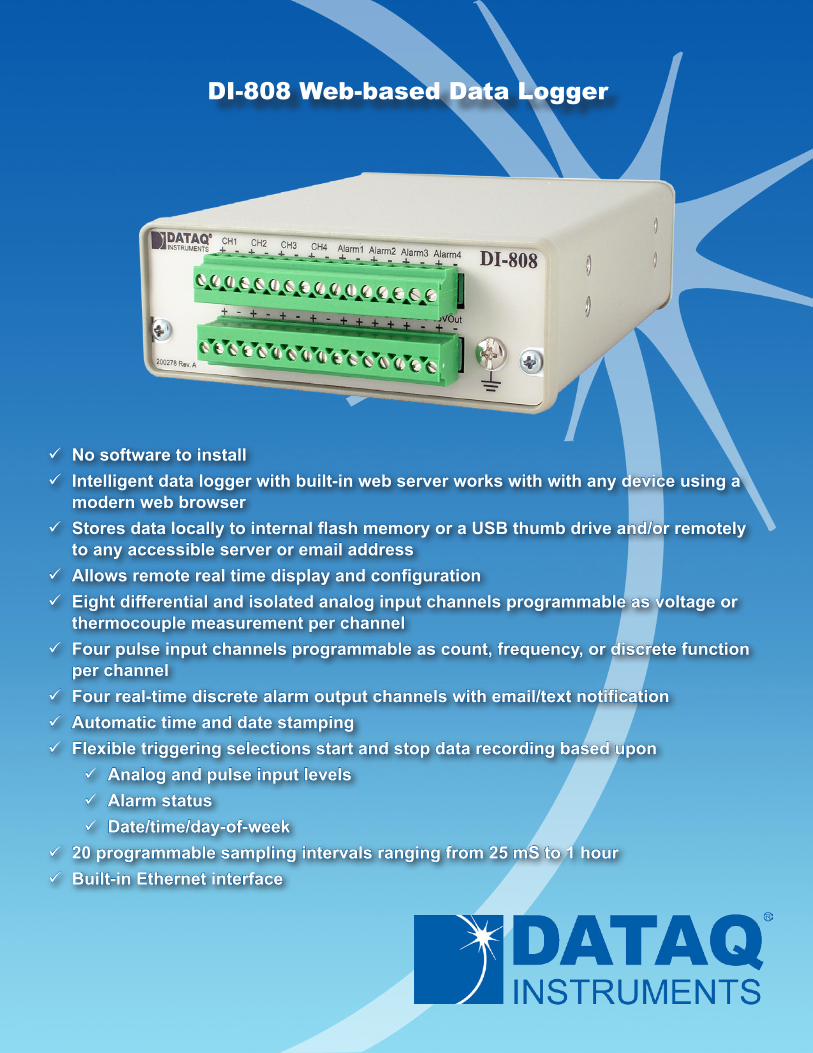
9 No software to install 9 Intelligent data logger with built-in web server works with with any device using a
modern web browser 9 Stores data locally to internal flash memory or a USB thumb drive and/or remotely
to any accessible server or email address 9 Allows remote real time display and configuration 9 Eight differential and isolated analog input channels programmable as voltage or
thermocouple measurement per channel 9 Four pulse input channels programmable as count, frequency, or discrete function
per channel 9 Four real-time discrete alarm output channels with email/text notification 9 Automatic time and date stamping 9 Flexible triggering selections start and stop data recording based upon
9 Analog and pulse input levels 9 Alarm status 9 Date/time/day-of-week
9 20 programmable sampling intervals ranging from 25 mS to 1 hour 9 Built-in Ethernet interface
DI-808 Web-based Data Logger
DI-808 Description
www.dataq.com 2 330-668-1444
Web-based, Device-independent OperationModel DI-808 is a giant step forward in the evolution of data logger technology toward autonomous and device-independent operation. Its built-in web server allows you to access, configure, manage, and oversee in real time all aspects of the instrument’s measurement process using any device with a web browser running under any operating system. Just as you can navigate to Yahoo! using your favorite smart device, that same device can be used without exception with the DI-808. And because intelligence is built into the instrument, third party cloud services with their associated security risks and fee-based structures are avoided entirely. You stay in control at all levels, from device configuration and real time monitoring, to the acquired data and alarms the DI-808 places on your smart device. The DI-808’s Ethernet interface allows it to integrate with any existing local area network (LAN) or virtual private network (VPN.) And simple port forwarding exposes the instrument to the Internet, allowing remote access from any location on the planet.
Measurement FlexibilityBuilt around the DI-808’s web server is a powerful data logger engine that adapts to a wide range of analog and pulse measurements. Eight analog input channels feature channel-independent voltage and thermocouple configurations. Voltage measurements support ±10 mV to ±50 V measurements across twelve programmable ranges. Thermocouple configurations support J,K,T,B,R,S,E, and N types. Full channel isolation allows virtually any measurement in tough industrial environments: grounded thermocouples, powered thermocouples, off-ground current shunts, as well as unexpected and unknown ground potential differences. Complementing the analog input channels are four pulse inputs. Each can be independently programmed for simple state detection, to operate as a counter, or make a frequency measurement. Use these functions to acquire, for example, volume data from a flow sensor (count), and flow rate (frequency.) Other examples are rpm measurements or simple counting in production or product life test applications. Both analog and pulse measurements are reported synchronously in the same sampling interval, and all measurements are time-and-date-stamped. Sampling intervals are pro-grammable as often as once every 25 mS or as infrequently as once every hour, with 18 selectable intervals in between. There’s even an external option to synchronize sampling to external events.
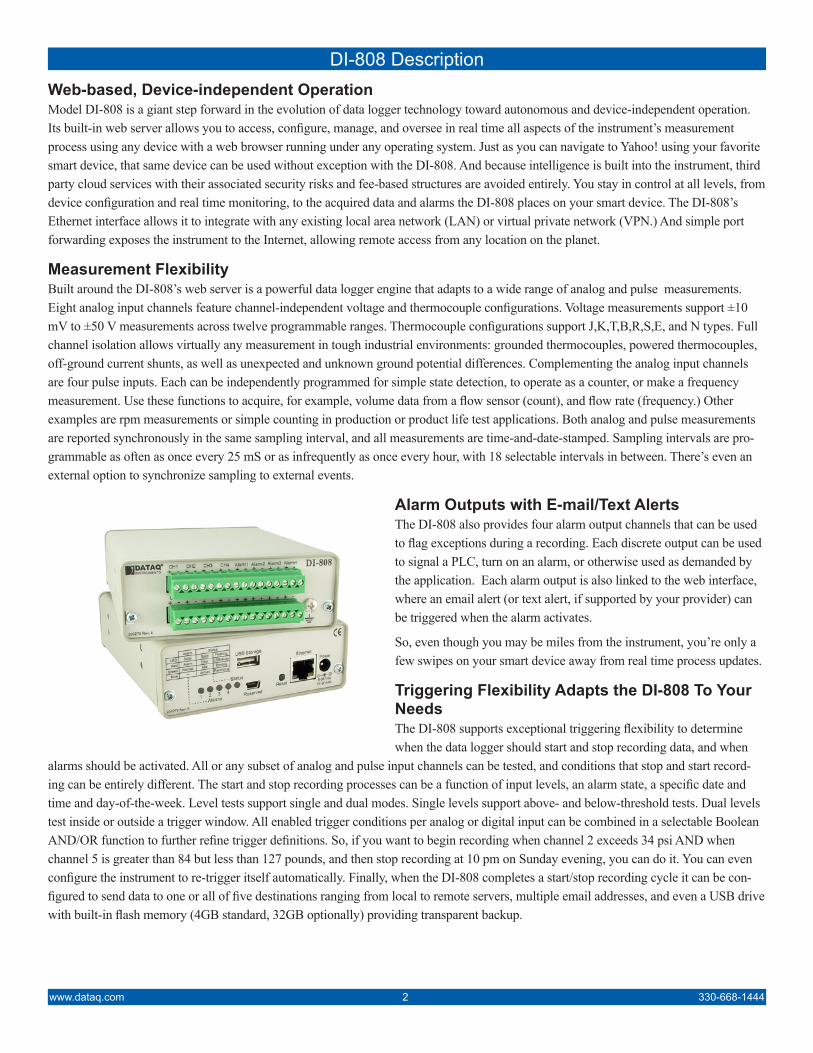
Alarm Outputs with E-mail/Text AlertsThe DI-808 also provides four alarm output channels that can be used to flag exceptions during a recording. Each discrete output can be used to signal a PLC, turn on an alarm, or otherwise used as demanded by the application. Each alarm output is also linked to the web interface, where an email alert (or text alert, if supported by your provider) can be triggered when the alarm activates.
So, even though you may be miles from the instrument, you’re only a few swipes on your smart device away from real time process updates.
Triggering Flexibility Adapts the DI-808 To Your Needs The DI-808 supports exceptional triggering flexibility to determine when the data logger should start and stop recording data, and when
alarms should be activated. All or any subset of analog and pulse input channels can be tested, and conditions that stop and start record-ing can be entirely different. The start and stop recording processes can be a function of input levels, an alarm state, a specific date and time and day-of-the-week. Level tests support single and dual modes. Single levels support above- and below-threshold tests. Dual levels test inside or outside a trigger window. All enabled trigger conditions per analog or digital input can be combined in a selectable Boolean AND/OR function to further refine trigger definitions. So, if you want to begin recording when channel 2 exceeds 34 psi AND when channel 5 is greater than 84 but less than 127 pounds, and then stop recording at 10 pm on Sunday evening, you can do it. You can even configure the instrument to re-trigger itself automatically. Finally, when the DI-808 completes a start/stop recording cycle it can be con-figured to send data to one or all of five destinations ranging from local to remote servers, multiple email addresses, and even a USB drive with built-in flash memory (4GB standard, 32GB optionally) providing transparent backup.
330-668-1444 3 www.dataq.com
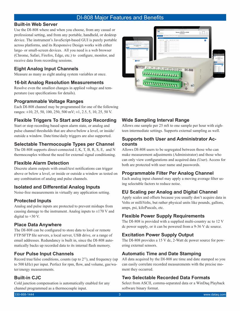
Built-in Web ServerUse the DI-808 where and when you choose, from any casual or professional setting, and from any portable, handheld, or desktop device. The instrument’s JavaScript-based GUI is purely portable across platforms, and its Responsive Design works with either large- or small-screen devices. All you need is a web browser (Chrome, Safari, Firefox, Edge, etc.) to configure, monitor, and receive data from recording sessions.
Eight Analog Input ChannelsMeasure as many as eight analog system variables at once.
16-bit Analog Resolution MeasurementsResolve even the smallest changes in applied voltage and tem-perature (see specifications for details).
Programmable Voltage RangesEach DI-808 channel may be programmed for one of the following ranges: ±10, 25, 50, 100, 250, 500 mV; ±1, 2.5, 5, 10, 25, 50 V.
Flexible Triggers To Start and Stop RecordingStart or stop recording based upon alarm state, or analog and pulse channel thresholds that are above/below a level, or inside/outside a window. Date/time/daily triggers are also supported.
Selectable Thermocouple Types per ChannelThe DI-808 supports direct-connected J, K, T, B, R, S, E, and N thermocouples without the need for external signal conditioning.
Flexible Alarm DetectionDiscrete alarm outputs with email/text notifications can trigger above or below a level, or inside or outside a window as tested on any combination of analog and pulse channels.
Isolated and Differential Analog InputsNoise-free measurements in virtually any application setting.
Protected Inputs Analog and pulse inputs are protected to prevent mishaps from causing damage to the instrument. Analog inputs to ±170 V and digital to +30 V.
Place Data AnywhereThe DI-808 can be configured to store data to local or remote FTP/SFTP file servers, a local server, USB drive, or a range of email addresses. Redundancy is built in, since the DI-808 auto-matically backs up recorded data to its internal flash memory.
Four Pulse Input ChannelsRecord true/false conditions, counts (up to 232), and frequency (up to 500 kHz) per input. Perfect for rpm, flow, and volume, gas/wa-ter/energy measurements.
Built-in CJC Cold junction compensation is automatically enabled for any channel programmed as a thermocouple input.
DI-808 Major Features and Benefits
Wide Sampling Interval RangeAllows one sample per 25 mS to one sample per hour with eigh-teen intermediate settings. Supports external sampling as well.
Supports both User and Administrator Ac-counts Allows DI-808 users to be segregated between those who can make measurement adjustments (Administrator) and those who can only view configurations and acquired data (User). Access for both are protected with user name and passwords.
Programmable Filter Per Analog ChannelEach analog input channel may apply a moving average filter us-ing selectable factors to reduce noise.
EU Scaling per Analog and Digital Channel Apply scales and offsets because you usually don’t acquire data in Volts or milliVolts, but rather physical units like pounds, gallons, amps, psi, kiloPascals, etc.
Flexible Power Supply RequirementsThe DI-808 is provided with a supplied multi-country ac to 12 V dc power supply, or it can be powered from a 9-36 V dc source.
Excitation Power Supply OutputThe DI-808 provides a 15 V dc, 2-Watt dc power source for pow-ering external sensors.
Automatic Time and Date StampingAll data acquired by the DI-808 are time and date stamped so you can easily correlate recorded measurements with the precise mo-ment they occurred.
Two Selectable Recorded Data FormatsSelect from ASCII, comma-separated data or a WinDaq Playback software binary format.
www.dataq.com 4 330-668-1444
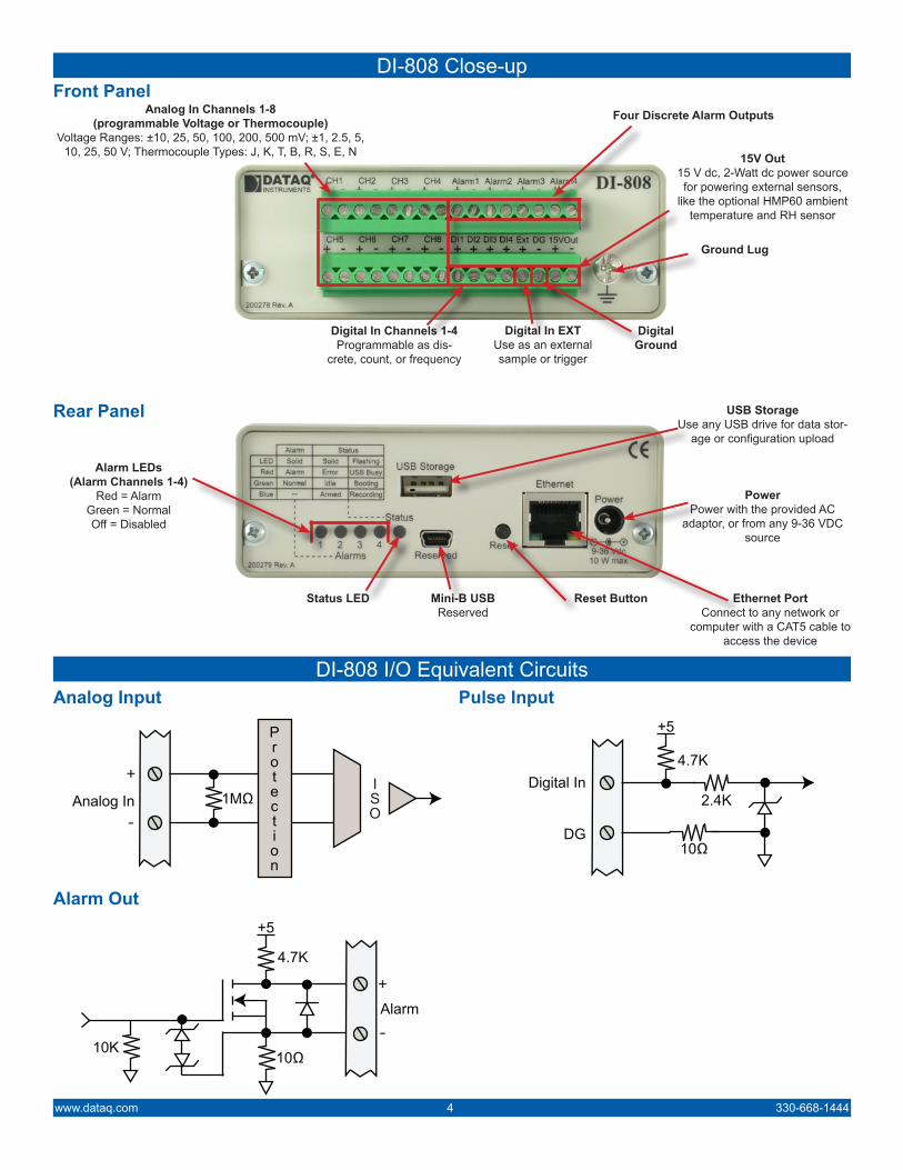
DI-808 I/O Equivalent CircuitsAnalog Input Pulse Input
Alarm Out
Analog In 1MΩ
+5
Alarm
10Ω
4.7K
10K
Digital In
10ΩDG
4.7K
+5
2.4K
DI-808 Close-upFront Panel
Rear Panel
Analog In Channels 1-8(programmable Voltage or Thermocouple)
Voltage Ranges: ±10, 25, 50, 100, 200, 500 mV; ±1, 2.5, 5, 10, 25, 50 V; Thermocouple Types: J, K, T, B, R, S, E, N
Four Discrete Alarm Outputs
Digital In Channels 1-4Programmable as dis-
crete, count, or frequency
Digital In EXTUse as an externalsample or trigger
Digital Ground
15V Out15 V dc, 2-Watt dc power source for powering external sensors,
like the optional HMP60 ambient temperature and RH sensor
Ground Lug
Alarm LEDs(Alarm Channels 1-4)
Red = AlarmGreen = NormalOff = Disabled
Status LED
USB StorageUse any USB drive for data stor-
age or configuration upload
Ethernet PortConnect to any network or
computer with a CAT5 cable to access the device
PowerPower with the provided AC
adaptor, or from any 9-36 VDC source
Reset ButtonMini-B USBReserved
330-668-1444 5 www.dataq.com
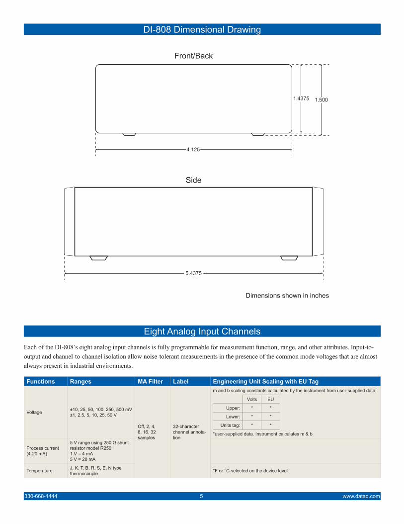
DI-808 Dimensional Drawing
Eight Analog Input ChannelsEach of the DI-808’s eight analog input channels is fully programmable for measurement function, range, and other attributes. Input-to-output and channel-to-channel isolation allow noise-tolerant measurements in the presence of the common mode voltages that are almost always present in industrial environments.
Functions Ranges MA Filter Label Engineering Unit Scaling with EU Tag
Voltage ±10, 25, 50, 100, 250, 500 mV±1, 2.5, 5, 10, 25, 50 V
Off, 2, 4, 8, 16, 32 samples
32-character channel annota-tion
m and b scaling constants calculated by the instrument from user-supplied data:
Volts EU
Upper: * *
Lower: * *
Units tag: * *
*user-supplied data. Instrument calculates m & b
Process current(4-20 mA)
5 V range using 250 Ω shunt resistor model R250:1 V = 4 mA5 V = 20 mA
Temperature J, K, T, B, R, S, E, N type thermocouple °F or °C selected on the device level
Side
Front/Back
4.125
1.4375 1.500
5.4375
Dimensions shown in inches
www.dataq.com 6 330-668-1444
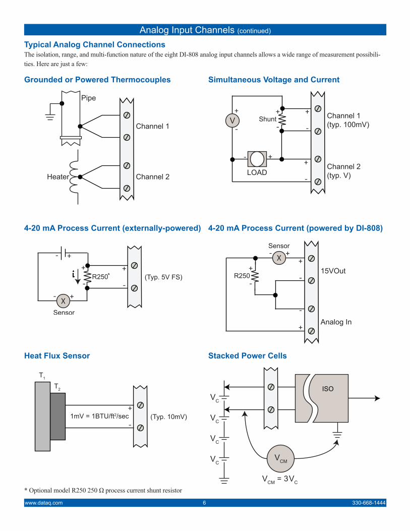
Grounded or Powered Thermocouples Simultaneous Voltage and Current
4-20 mA Process Current (externally-powered) 4-20 mA Process Current (powered by DI-808)
Channel 1
Channel 2Heater
Pipe
Channel 1(typ. 100mV)
Channel 2(typ. V)LOAD
Shunt
(Typ. 5V FS)15VOut
Analog In
R250
Heat Flux Sensor Stacked Power Cells
(Typ. 10mV)1mV = 1BTU/ft2/sec
T2
T1
ISO
* Optional model R250 250 Ω process current shunt resistor
Typical Analog Channel ConnectionsThe isolation, range, and multi-function nature of the eight DI-808 analog input channels allows a wide range of measurement possibili-ties. Here are just a few:
Analog Input Channels (continued)
330-668-1444 7 www.dataq.com
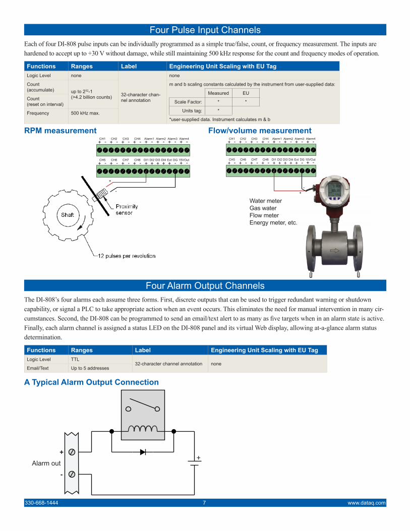
Four Pulse Input ChannelsEach of four DI-808 pulse inputs can be individually programmed as a simple true/false, count, or frequency measurement. The inputs are hardened to accept up to +30 V without damage, while still maintaining 500 kHz response for the count and frequency modes of operation.
Functions Ranges Label Engineering Unit Scaling with EU TagLogic Level none
32-character chan-nel annotation
none
Count (accumulate) up to 232-1
(>4.2 billion counts)
m and b scaling constants calculated by the instrument from user-supplied data:
Measured EU
Scale Factor: * *
Units tag: *
*user-supplied data. Instrument calculates m & b
Count(reset on interval)
Frequency 500 kHz max.
RPM measurement Flow/volume measurement
+
- +-
Four Alarm Output ChannelsThe DI-808’s four alarms each assume three forms. First, discrete outputs that can be used to trigger redundant warning or shutdown capability, or signal a PLC to take appropriate action when an event occurs. This eliminates the need for manual intervention in many cir-cumstances. Second, the DI-808 can be programmed to send an email/text alert to as many as five targets when in an alarm state is active. Finally, each alarm channel is assigned a status LED on the DI-808 panel and its virtual Web display, allowing at-a-glance alarm status determination.
Functions Ranges Label Engineering Unit Scaling with EU TagLogic Level TTL
32-character channel annotation noneEmail/Text Up to 5 addresses
A Typical Alarm Output Connection
Alarm out
Water meterGas waterFlow meterEnergy meter, etc.
www.dataq.com 8 330-668-1444
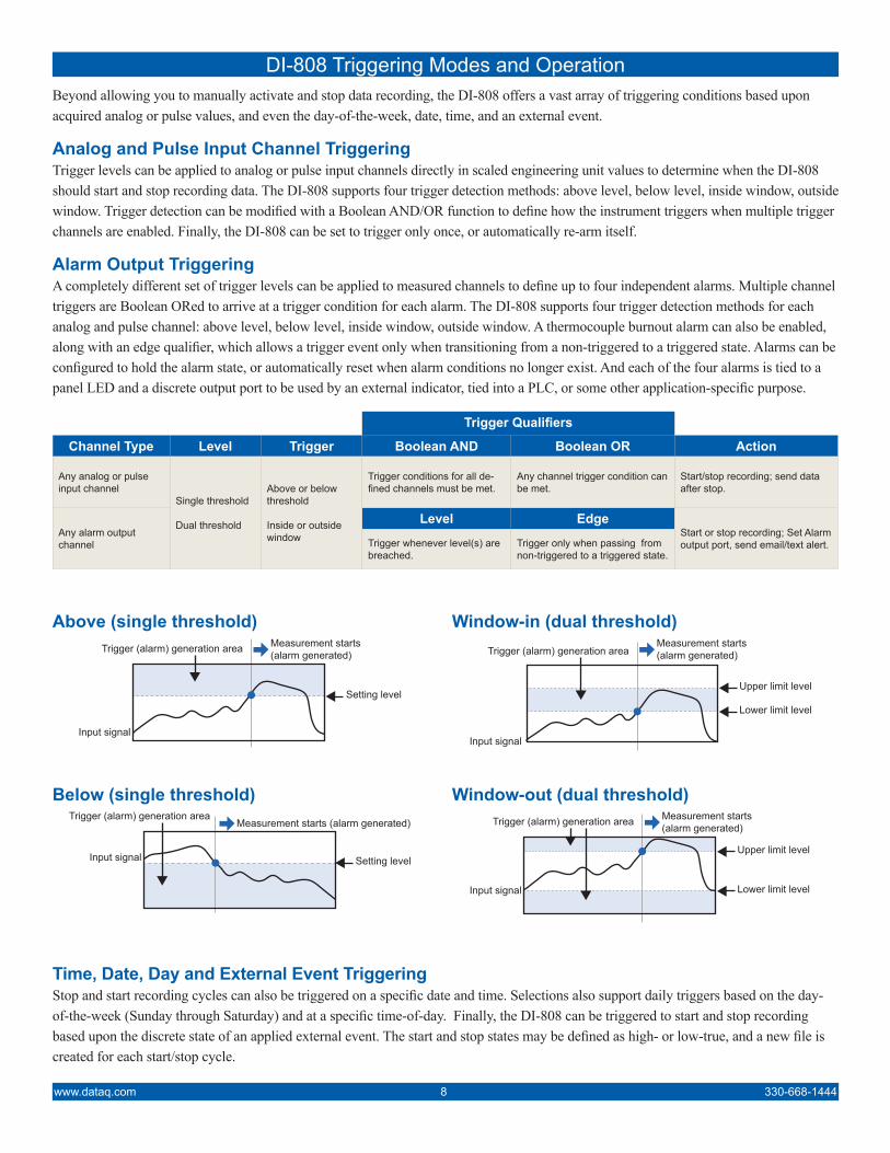
DI-808 Triggering Modes and OperationBeyond allowing you to manually activate and stop data recording, the DI-808 offers a vast array of triggering conditions based upon acquired analog or pulse values, and even the day-of-the-week, date, time, and an external event.
Analog and Pulse Input Channel Triggering Trigger levels can be applied to analog or pulse input channels directly in scaled engineering unit values to determine when the DI-808 should start and stop recording data. The DI-808 supports four trigger detection methods: above level, below level, inside window, outside window. Trigger detection can be modified with a Boolean AND/OR function to define how the instrument triggers when multiple trigger channels are enabled. Finally, the DI-808 can be set to trigger only once, or automatically re-arm itself.
Alarm Output Triggering A completely different set of trigger levels can be applied to measured channels to define up to four independent alarms. Multiple channel triggers are Boolean ORed to arrive at a trigger condition for each alarm. The DI-808 supports four trigger detection methods for each analog and pulse channel: above level, below level, inside window, outside window. A thermocouple burnout alarm can also be enabled, along with an edge qualifier, which allows a trigger event only when transitioning from a non-triggered to a triggered state. Alarms can be configured to hold the alarm state, or automatically reset when alarm conditions no longer exist. And each of the four alarms is tied to a panel LED and a discrete output port to be used by an external indicator, tied into a PLC, or some other application-specific purpose.
Trigger Qualifiers
Channel Type Level Trigger Boolean AND Boolean OR Action
Any analog or pulse input channel
Single threshold
Dual threshold
Above or below threshold
Inside or outside window
Trigger conditions for all de-fined channels must be met.
Any channel trigger condition can be met.
Start/stop recording; send data after stop.
Any alarm output channel
Level EdgeStart or stop recording; Set Alarm output port, send email/text alert.Trigger whenever level(s) are
breached.Trigger only when passing from non-triggered to a triggered state.
Measurement starts(alarm generated)Trigger (alarm) generation area
Input signal
Setting level
Measurement starts (alarm generated)Trigger (alarm) generation area
Input signal Setting level
Measurement starts(alarm generated)Trigger (alarm) generation area
Input signal
Upper limit level
Lower limit level
Measurement starts(alarm generated)Trigger (alarm) generation area
Input signal
Upper limit level
Lower limit level
Above (single threshold) Window-in (dual threshold)
Below (single threshold) Window-out (dual threshold)
Time, Date, Day and External Event Triggering Stop and start recording cycles can also be triggered on a specific date and time. Selections also support daily triggers based on the day-of-the-week (Sunday through Saturday) and at a specific time-of-day. Finally, the DI-808 can be triggered to start and stop recording based upon the discrete state of an applied external event. The start and stop states may be defined as high- or low-true, and a new file is created for each start/stop cycle.
330-668-1444 9 www.dataq.com
Data Storage Formats and DestinationsWhen a recording session terminates, either automatically by the DI-808’s trigger facilities, or manually by your command, data can be placed on any combination of targets. The recorded record can be:
• Emailed to one or several addresses
• Stored to a server drive on the same LAN as the DI-808
• Uploaded to an FTP or Secure FTP server
• Stored to a USB drive plugged into a dedicated DI-808socket reserved for that purpose
Regardless of destination, a backup of recorded data is transparently and automatically stored to the DI-808’s internal flash memory, where it’s always available until deleted. Two internal memory capacities are available: 4 GB and 32 GB. Data file format is selectable as either CSV (comma-separated value) or high resolution WinDaq file (.WDH). WinDaq is a binary format and therefore much smaller in size for a given amount of recorded data than is the ASCII CSV format. However, WinDaq-formatted files must be viewed using a free, downloadable Playback utility that runs only under Windows, while a CSV file can be viewed using any device.
Automatic Time and Date StampingEvery file recorded by the DI-808, and every sample in it is time and date stamped. The DI-808 has a battery-backed up date and time clock embedded in its hardware design. This clock may be synchronized to the clock of any connected PC, or to a LAN- or Internet-based Network Time Protocol (NTP) server.
DI-808 User Access ControlAccess to the DI-808’s web server is controlled through two account levels: administrator and user. The administrator account has complete access to DI-808 features. The administrator can enable, disable, and configure channels, triggers, alarms, and more. Any and every programmable feature of the DI-808 can be accesses and changed by the administrator. In contrast, user accounts can only view settings and real time displays and are prevented from making any changes that could affect recorded data in any way. Both administrator and user accounts are separately password-protected.
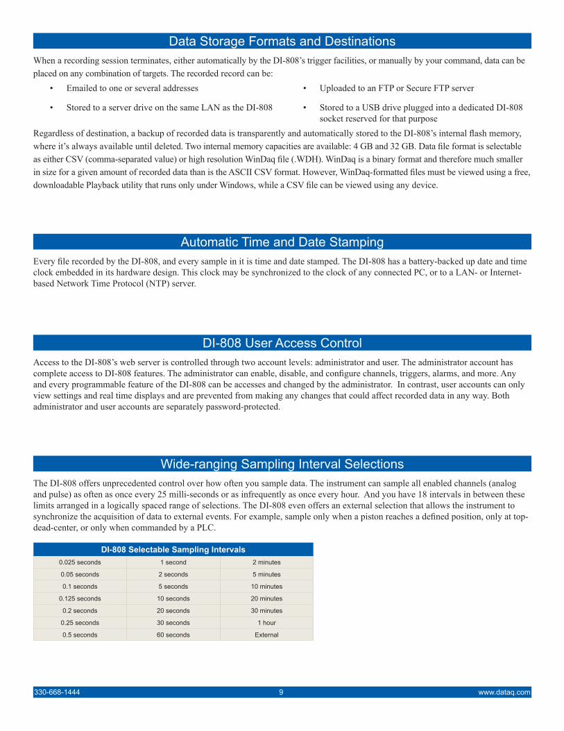
Wide-ranging Sampling Interval SelectionsThe DI-808 offers unprecedented control over how often you sample data. The instrument can sample all enabled channels (analog and pulse) as often as once every 25 milli-seconds or as infrequently as once every hour. And you have 18 intervals in between these limits arranged in a logically spaced range of selections. The DI-808 even offers an external selection that allows the instrument to synchronize the acquisition of data to external events. For example, sample only when a piston reaches a defined position, only at top-dead-center, or only when commanded by a PLC.
DI-808 Selectable Sampling Intervals0.025 seconds 1 second 2 minutes
0.05 seconds 2 seconds 5 minutes
0.1 seconds 5 seconds 10 minutes
0.125 seconds 10 seconds 20 minutes
0.2 seconds 20 seconds 30 minutes
0.25 seconds 30 seconds 1 hour
0.5 seconds 60 seconds External
www.dataq.com 10 330-668-1444
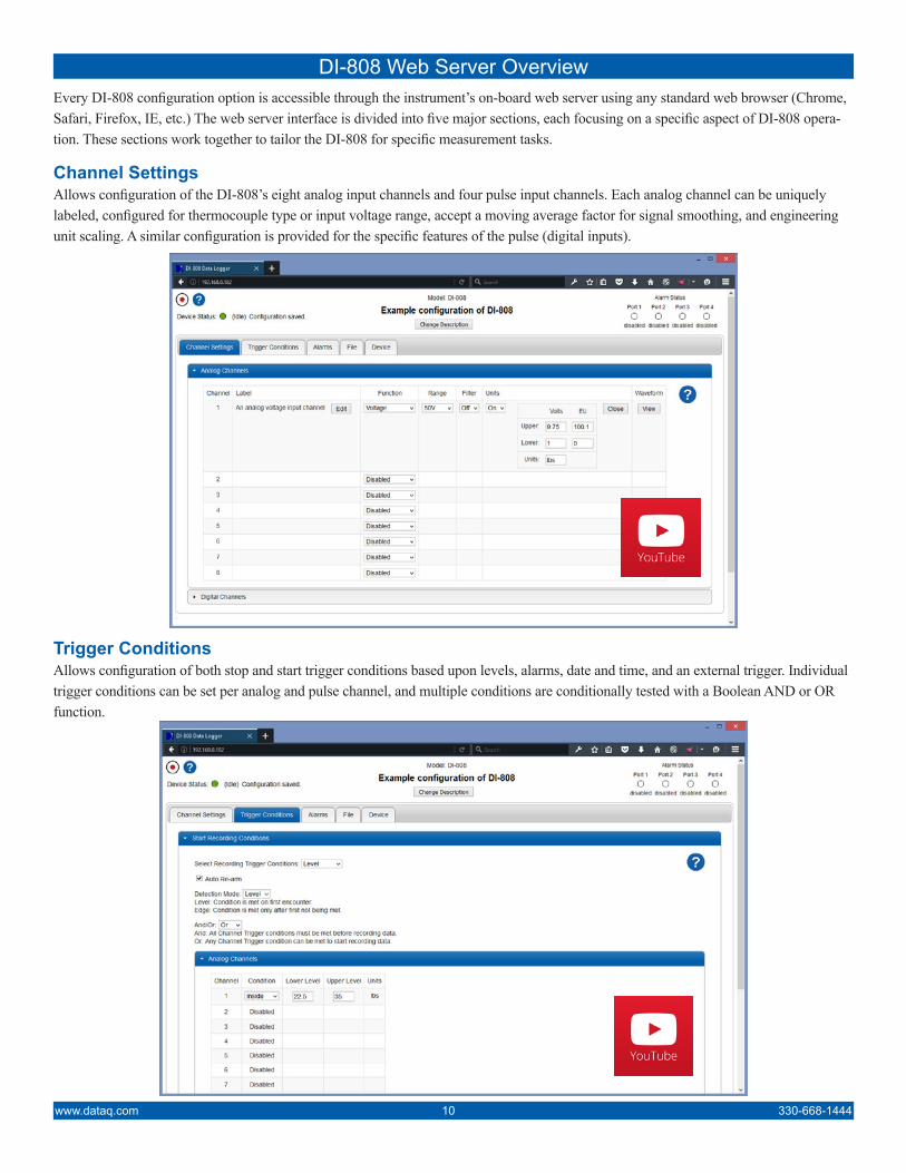
DI-808 Web Server OverviewEvery DI-808 configuration option is accessible through the instrument’s on-board web server using any standard web browser (Chrome, Safari, Firefox, IE, etc.) The web server interface is divided into five major sections, each focusing on a specific aspect of DI-808 opera-tion. These sections work together to tailor the DI-808 for specific measurement tasks.
Channel Settings Allows configuration of the DI-808’s eight analog input channels and four pulse input channels. Each analog channel can be uniquely labeled, configured for thermocouple type or input voltage range, accept a moving average factor for signal smoothing, and engineering unit scaling. A similar configuration is provided for the specific features of the pulse (digital inputs).
Trigger Conditions Allows configuration of both stop and start trigger conditions based upon levels, alarms, date and time, and an external trigger. Individual trigger conditions can be set per analog and pulse channel, and multiple conditions are conditionally tested with a Boolean AND or OR function.
330-668-1444 11 www.dataq.com
DI-808 Web Server Overview (continued)
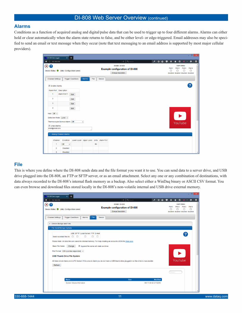
Alarms Conditions as a function of acquired analog and digital/pulse data that can be used to trigger up to four different alarms. Alarms can either hold or clear automatically when the alarm state returns to false, and be either level- or edge-triggered. Email addresses may also be speci-fied to send an email or text message when they occur (note that text messaging to an email address is supported by most major cellular providers).
File This is where you define where the DI-808 sends data and the file format you want it to use. You can send data to a server drive, and USB drive plugged into the DI-808, an FTP or SFTP server, or as an email attachment. Select any one or any combination of destinations, with data always recorded to the DI-808’s internal flash memory as a backup. Also select either a WinDaq binary or ASCII CSV format. You can even browse and download files stored locally in the DI-808’s non-volatile internal and USB drive external memory.
www.dataq.com 12 330-668-1444
DI-808 Web Server Overview (continued)
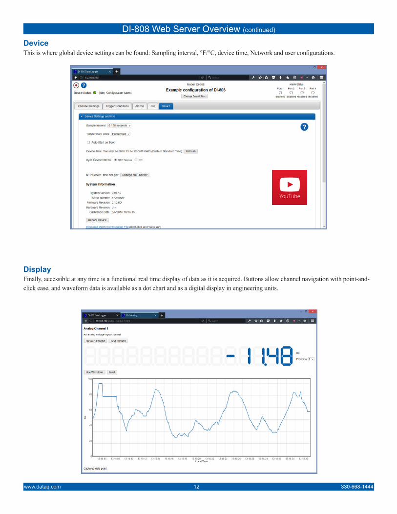
Device This is where global device settings can be found: Sampling interval, °F/°C, device time, Network and user configurations.
Display Finally, accessible at any time is a functional real time display of data as it is acquired. Buttons allow channel navigation with point-and-click ease, and waveform data is available as a dot chart and as a digital display in engineering units.
Analog InputsNumber of Channels: 8
Configuration: Differential, IsolatedIsolation: Input-to-output, channel-to-channel
Measurement type per channel: Voltage, ThermocoupleProgrammable thermocouple types
and measurement range per channel:
Over 25 ±3 °C ambient temperature rangeStable ambient temperature
Following 60 minutes warm-upExcluding common mode errorExcluding thermocouple error
TC type
Temperature Measurement
range (°C)Accuracy (°C)
J -190 to 1200±(0.1% of span + 2)
K -180 to 1360T -190 to 400 ±(0.1% of span + 1)
B600 to 1000 ±(0.2% of span + 4)
1001 to 1810 ±(0.1% of span + 3)
R-40 to 300 ±(0.2% of span + 6)
301 to 1760 ±(0.1% of span + 3)
S-40 to 400 ±(0.2% of span + 6)
401 to 1750 ±(0.1% of span +3)E -160 to 990 ±(0.1% of span + 1)
N-170 to 50 ±(0.1% of span + 3)
51 to 1290 ±(0.1% of span + 1)
Programmable voltage ranges per channel:
At 25 °C ambient temperatureFollowing 30 minutes warm-upExcluding common mode error
Range (±) Accuracy10 mV
±(0.05% of span + 10 µV)
25 mV50 mV
100 mV250 mV500 mV
1 V2.5 V5 V
10 V25 V50 V
Input impedance: 1MΩ all rangesAbsolute maximum input without
damage:120 V (±dc or rms)
Maximum common mode voltage: 120 V (±dc or rms)Minimum common mode rejection:
(330Ω unbalance)>100 dB (dc to 60 Hz)
Channel-to-channel crosstalk rejection: (Rsource ≤ 330Ω; Freqsource ≤ 60 Hz)
>110 dB
Alarm and trigger hysteresis: Voltage: ±0.5% of the full scale range; Temperature: ±0.3 °C
Digital/Pulse InputsNumber of channels: 4
Pull-up value: 4.7 kΩIsolation: None
Input high voltage threshold: 1.80 V minimumInput low voltage threshold: 1.40 V maximum
Absolute voltage (V) input without damage:
0 ≤ V ≤ 30 V
Maximum count value: 232 - 1 (.csv format)65,535 (WinDaq format)
Maximum measured frequency: >100 kHz (.csv format)65,565 Hz (WinDaq format)
Alarm OutputsNumber of channels: 4
Maximum drain voltage: 30 VMaximum sink current: 100 mA
DI-808 SpecificationsADC Characteristics
Voltage measurement Resolution: Range (±) Resolution Units10 mV 305
nV25 mV 76350 mV 1.52
μV
100 mV 305250 mV 763500 mV 15.3
1 V 30.52.5 V 76.35 V 152.6
10 V 30525 V 76350 V 1.53 mV
Minimum temperature measurement resolution:
TC type Resolution UnitsJ 0.086
°C
K 0.096T 0.037B 0.096
R/S 0.111E 0.073N 0.092
4-20 mA current loop resolution:(±5 V range with 250Ω shunt resistor)
26,214 ADC counts over the 4-20 mA range
Programmable sampling intervals: 25, 50, 100, 250, 500 mS1, 2, 5, 10, 20, 30 S1, 2, 5, 10, 20, 30 minutes1 hour, External
Internal MemoryType: Non-volatile flashSize: 4 GB (standard); 32 GB (optional)Use: Automatic backup of recorded data
Indicators and ControlsSignal I/O: Dual, removable 16-position screw
terminal connectorsPower connector: 2.0 mm center pin, 5 mm shell
Status light: One multicolor LED indicating status
Alarm lights: 4 multicolor LEDsEthernet interface connector: RJ45
USB drive receptacle: Type A maleUSB connector: Mini B style (usage is reserved)Control button: Push type to set device operating
modeGround: Screw terminal to establish Earth
ground.
Power I/OInput power requirements: 9-36 V dc @ 7.5 Watts
9-36 V dc @ 10 Watts (w/excitation)Excitation power supply output: 15 V, 130 mA max, 13 mA min
EnvironmentalOperating temperature range: 0 to 70 °C (32 to 158°F)
Storage temperature: -20 to 70 °C (-4 to 158°F)Storage humidity: 0-90%RH, non-condensing
Physical CharacteristicsEnclosure: All-metal. Steel top, aluminum baseMounting: Desktop, Bulkhead with optional
bracketsDimensions: 57/16 D × 41/8 W × 11/2 H inches
13.81D × 10.48W × 3.81H cmWeight: <1 lb. (<453 grams)
330-668-1444 13 www.dataq.com
www.dataq.com 14 330-668-1444
Configurable ComponentsNetwork variables: IP address, Subnet mask, Gateway,
DNSAccount log-on information: For FTP, SFTP, SMB, SMTP
User log-on information: User and administrator names and passwords
Supported StandardsNetwork Time Protocol (NTP): Syncs internal time and date clock to
Internet timeFile Transfer Protocol (FTP): Allows the instrument to push re-
corded data to an FTP/SFTP serverSecured File Transfer Protocol (SFTP):Server Message Block (SMB) protocol: Allows the instrument to record data
to a local server driveSimple Mail Transfer Protocol
(SMTP):Allows the instrument to send data and alarms to multiple email addresses
Display SubsystemDigital display: Numeric display of acquired values
scaled into engineering units in real time. Selectable precision of 1 to four digits to the right of the decimal point.
Waveform display: Scrolling plot of selected channel data in real time versus time of day.
Alarms status: Virtual LEDs display the status of the four alarm outputs
Channel Settings SubsystemAnalog channel configuration: Voltage and measurement range,
temperature and thermocouple type, moving average filter, engineering units, channel label
Digital/pulse channels: Discrete, count, count with reset, frequency, engineering units, chan-nel label
Trigger SubsystemStart or stop recording trigger condi-
tions:Level: Above/below level, In/out windowAlarm: Upon alarm activationDate/time: Specific date and time. Daily selectionExternal
Auto rearm: Enabled or disabled
DI-808 Specifications (continued)
Alarm SubsystemLevel or edge selection: Level: Alarm is activated when
alarm condition is met on first encounterEdge: Alarm is activated only after first not being met.
Analog/pulse channel levels: Above/below level, In/out windowThermocouple burnout: Any burnout detected on a TC
channelSelectable alarm ports: 1-4
Alarm hold: Enable/disable
File SubsystemFile browse/download: Browse files on the DI-808 internal
flash memory or connected USB drive and allow selectable down-loads to the client device.
Format local file storage: Formats internal flash memory, erasing previously recorded files and reallocating file space for new recorded data.
Get local file space: Returns the available file space.Base file name: Allows recorded files to be assigned
a definable file name, and to option-ally have date and time appended.
File type: Allows the recorded file format to be defined as either ASCII CSV or binary WDH.
Device SubsystemDevice settings and information: Program device sampling interval,
temperature units (°F/°C), enable or disable auto start on boot feature, time/date/ synched to connected PC or NTP server, reboot device.
Network configuration: Configure device IP address, DNS, Subnet mask, Gateway.
Users and accounts: Configure user and administrator names and passwords.
Description Order No.DI-808 Web-based Data logger with 4GB MemoryIncludes DI-808, ac adaptor, NIST-traceable calibra-tion certificate. Provides 4 GB of non-volatile internal data file storage.
DI-808
250Ω 4-20 mA shunt resistor±0.1%, 0.5 Watts max., ±50 ppm/°C
R250
Ambient Temp and RH Sensor-40 to +60 °C, 0 to 100% RH Measurement Range. Powered by the DI-808.
HMP60
Mounting bracketRight-angle mounting brackets for bulkhead mounting model DI-808.
100947-1
Ordering GuideDescription Order No.DI-808 Web-based Data logger with 32GB MemoryIncludes DI-808, ac adaptor, NIST-traceable cali-bration certificate. Provides 32 GB of non-volatile internal data file storage.
DI-808-32
Power ConnectorDc power connector for powering the DI-808 from a source other than the provided ac adaptor.
200300
Bottom Screw Terminal BlockSpare 16-port removable screw terminal block for BOTTOM of DI-808 screw terminal block receptacle.
100995-MCVW
Top Screw Terminal BlockSpare 16-port removable screw terminal block for TOP of DI-808 screw terminal block receptacle.
100995-MCVR
241 Springside DriveAkron, Ohio 44333
Phone: 330-668-1444Fax: 330-666-5434
Data Acquisition Product Links(click on text to jump to page)Data Acquisition | Data Logger
DATAQ, the DATAQ logo and WinDaq are registered trademarks of DATAQ Instruments, Inc. All rights reserved. Copyright © 2016 DATAQ Instruments, Inc.The information on this data sheet is subject to change without notice.