Embed Size (px)
Citation preview
USER’S MANUALVERSION 3.0
DDDDDIAGNOSTICIAGNOSTICIAGNOSTICIAGNOSTICIAGNOSTIC
AND
REPROGRAMMING
TOOL
IMPORTANT NOTICE
SAFETYAll Danger, Warning and important notes must be followed for your safety. These safety messages will bein the following formats:
• Danger means you may risk possible loss of life;• Warning means you may risk bodily harm;• Important means you risk damage to the vehicle or the tool;• Notes are added to provide clarity and helpful tips.
These safety messages cover situations SPX is aware of. SPX cannot know, evaluate and advise you asto all of the possible hazards. You must be certain that your personal safety is not jeopardized by anyconditions or service procedures encountered.
COPYRIGHTNo part of this manual may be reproduced, stored in a retrieval system or transmitted, in any form or byany means, electronic, mechanical, photocopying, recording, or otherwise, without the prior writtenpermission of SPX.
DISCLAIMERAll information, illustrations, and specifications contained in this technical instruction manual are based onthe latest information available at the time of publication. The right is reserved to make changes at anytime without obligation to notify any person or organization of such revisions or changes. Further, SPXshall not be liable for errors contained herein or for incidental or consequential damages (including lostprofits) in connection with the furnishing, performance or use of this material.

Getting Started • 1
Contents Precautions
Reprog Scan Tool:❚➤REPROGRAM VEHICLE2- GENERIC OBD II3- TROUBLE CODES
↓
Danger• When an engine is operating, keep the
service area WELL VENTILATED orattach a building exhaust removalsystem to the engine exhaust system.Engines produce carbon monoxide, anodorless, poisonous gas that causesslower reaction time and can lead toserious injury or death.
Warning• Set the parking brake and block the
wheels before testing or repairing thevehicle. It is especially important toblock the wheels on front-wheel drivevehicles because the parking brakedoes not hold the drive wheels.
• Be sure there is adequate clearancebetween any moving components whentesting. Moving components and beltscan “catch” loose clothing, parts of yourbody or the test equipment and causeserious damage or personal injury.
• Wear an ANSI approved eye shield whentesting or repairing vehicles. Objects canbe propelled by whirling engine compo-nents and liquids escaping underpressure can cause serious injury.
• Automotive batteries contain sulfuricacid and produce explosive gases thatcan result in serious injury. To preventignition of gases, keep lighted ciga-rettes, sparks, flames, and other ignitionsources away from the battery at alltimes. If you are using the battery as apower source, connect the RED (+)battery clip to the positive vehiclebattery terminal and connect the BLACK(-) battery clip to a good ground awayfrom the battery.
Important:• Do not leave the tool for prolonged periods in the
direct sunlight, the display may darken due to excessheat.
Welcome .................................................. 2D.A.R.T. Basics ....................................................... 2Read Me First: Registration and Software Update.. 4
How to Update a Controller .................... 8Required Documentation ........................................ 8About Cable Setup .................................................. 8How do I Update a Controller .................................. 8
About Diagnostic Trouble Codes .........11How to Connect the Cable ..................................... 11How to Read Diagnostic Trouble Codes ................11
How to Program the Sentry Key .......... 12How to Connect the Cable .................................... 12How to Program Keys ........................................... 12How to Erase Keys................................................ 12
About Customer Preferences .............. 13How to Connect the Cable .................................... 13How to Set Customer Preferences........................ 13
Miscellaneous Tests ............................. 14About Pinion Factor ............................................... 14About Clutch Volume Index ................................... 14
About Vehicle Identification ................. 15How to Identify a Vehicle ....................................... 15How to Read an Engine Identification Number ..... 15How to Read a Transmission Identification Number 15How to Save an Identification Number to Memory 15
About Modem Setup ............................. 16About Dial-Up Number .......................................... 16About Modem Initiation String ............................... 16About Call Waiting Service .................................... 17
AppendixD.A.R.T. Menu View ............................... 18Cable Connection Locations................ 21Body Platform Designations ................ 22Index ....................................................... 23

2 • Getting Started
The Diagnostic and Reprogramming Tool (D.A.R.T.) isdesigned to reprogram vehicle controller software programsor change function settings on a Chrysler vehicle easier andfaster. This tool is designed to access the following areas:
• Reprogramming –when Chrysler releases softwareupdates for vehicle controllers, or when additionalfunctions and capabilities are added to the D.A.R.T.programming, you have the ability to update a vehicle ortool program with the software you download from theOTC Bulletin Board System
• Reset Customer Preferences –comfort and conve-nience features on Chrysler vehicles can be changed tomeet the customer’s desires. Turn warning chimes on oroff, enable or disable automatic door locks, set theheadlights to come on with the windshield wipers, andmore.
• Locksmith Function –many new Chrysler vehicles areequipped with a Sentry Key Immobilizer System (SKIS).This system uses a vehicle immobilizer to preventvehicle theft. D.A.R.T. can program the SKIS driver’s keyto the vehicle or erase the key from the vehicle system ifit is lost or stolen.
• Diagnostic Trouble Code Reader –Read and eraseDiagnostic Trouble Codes (DTCs) on generic OBD IIsystems plus 1989-’98 Chrysler Engine ManagementSystems, SIR, BODY and many other Chrysler systems.
WelcomeD.A.R.T. BasicsThe D.A.R.T. is an easy-to-use test instrument that willstand up to rugged use. Take a moment to familiarizeyourself with the basic functional areas.
1. DB25 Port – Adapter cables plug into the DB25 port.
2. Display Window – display data and messages to the user.
3. Keypad – enter data and reply to tester messages. Keys listedperform the following functions:• UP/DOWN arrow keys –press to move through menus or
move the Selector Cursor up or down.• LEFT/RIGHT arrow keys –press to move the Selector Cursor
left, right, or move screen by screen through the menus.• F1/F2 keys –future option.• ENTER keys –enter your command into the tester.• EXIT keys– go back to the previous menu or test.• HELP key –display additional information.• RECORD key–future option
Figure 1.1: D.A.R.T.
1
2
3
CONTINUED ON NEXT PAGE...

Getting Started • 3
Cable Connection Error Messages
The D.A.R.T. produces an error message when it does notget a signal response (Fig. 1.2).
Figure 1.2: Error Message
An error may occur for the following reasons: • Poor connection: Check all cables and connections for a
tight fit and try again.• Low battery voltage: Recharge the battery.• Wrong cable used to connect to the Data Link Connector:
Verify that the correct cable is used.• Under certain circumstances the vehicle may lose
communications with the D.A.R.T. tool. Switch thevehicle ignition off, wait 15 seconds and then switch theignition on.
Program Icons
Program icons signal when functions are available or mustbe used to access more information.
• The Arrow Icon means more information is available.Press the ↓ or ↑ key to view the next screen.
Figure 1.3: Arrow Keys
• Press the HELP key to view additional instructions orinformation.
Figure 1.4: Help
• Move the Selector Cursor with the ↓ or ↑ arrow key toposition it beside an option you want to select, andthen press ENTER.
Figure 1.5: Selector
↔
❚➤
H
Typical Cable Setup
1. Refer to Cable Connections Locations in the Appen-dix to determine which cables are required toconnect the tool to the vehicle and to determinewhere the connector is located on the vehicle.
2. Connect the cables to the D.A.R.T. and to the vehicleData Link Connector or to the controller.
Typical setup to vehicle Data Link Connector
Figure 1.6: Data Link Connector Cable Setup
Typical setup for vehicle EATX II (Transaxle) Controller
Figure 1.7: EATX II Controller Setup3. Supply power to the tool, the program will automati-
cally initialize and identify the vehicle.
Power is supplied to the D.A.R.T. when the cable isconnected to the Data Link Connector (DLC), the controller,or when the cable battery clamp (if so equipped) is con-nected to the battery.
CCD Cable or SCIEngine CableDIN Cable
J1962/MMC, J1962 orMMC Cable
DIN Cable
EATX IIProgramming
Kit
Connect Red to Battery + andBlack to Battery – Terminal
Connect toEATX II
ControllerEATX II Controller
No Response, CheckCable, Ignition orD.A.R.T. Support Matrix.Press EXIT to Exit
4 • Getting Started
Read Me First: Registrationand Software UpdateBefore you can use all of the features of your D.A.R.T., youmust first perform two steps to set up your D.A.R.T. Tool:• Register your subscription on the OTC Bulletin Board
System (BBS).• Download the D.A.R.T. program software to update your
D.A.R.T. into a fully operational tool.
How to Register
For immediate registration, telephone 800-926-9430 andprovide the information required from the D.A.R.T. Registra-tion form, or fax your D.A.R.T. Registration form to 800-283-8665 for activation within 24 hours.
Figure 1.8: Registration Form
How to Update D.A.R.T. Software
Set up the D.A.R.T. with a modem to communicate with theOTC Bulletin Board Service (BBS).
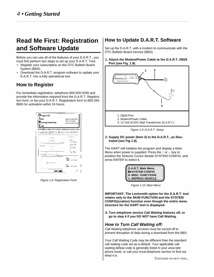
1. Attach the Modem/Power Cable to the D.A.R.T. DB25Port (see Fig. 1.9).
1. DB25 Port2. Modem/Power Cable3. 12 Volt AC/DC Wall Transformer (D.A.R.T.)
Figure 1.9: D.A.R.T. Setup
2. Supply DC power (Item 3) to the D.A.R.T., as illus-trated (see Fig 1.9).
The DART will initialize the program and display a MainMenu when power is supplied. Press the ↑ or ↓ key toposition the Selector Cursor beside SYSTEM CONFIG, andpress ENTER to select it.
IMPORTANT: The Locksmith option for the D.A.R.T. toolrelates only to the SKIM FUNCTION and the SYSTEMCONFIG(uration) function even though the entire menustructure for the DART tool is displayed.
3. Turn telephone service Call Waiting features off, orgo to step 4 if you DO NOT have Call Waiting.
How to Turn Call Waiting off:Call Waiting telephone services must be turned off toprevent disruption of data during a download from the BBS.
Your Call Waiting Code may be different than the standardcall waiting code set as a default. Your applicable callwaiting defeat code is generally listed in your area tele-phone book, or call your local telephone service to find outwhat it is.
D.A.R.T. Main Menu❚➤SYSTEM CONFIG8- MISC. FUNCTIONS1- REPROG VEHICLE
Figure 1.10: Main Menu
1 2
3
CONTINUED ON NEXT PAGE...
Getting Started • 5
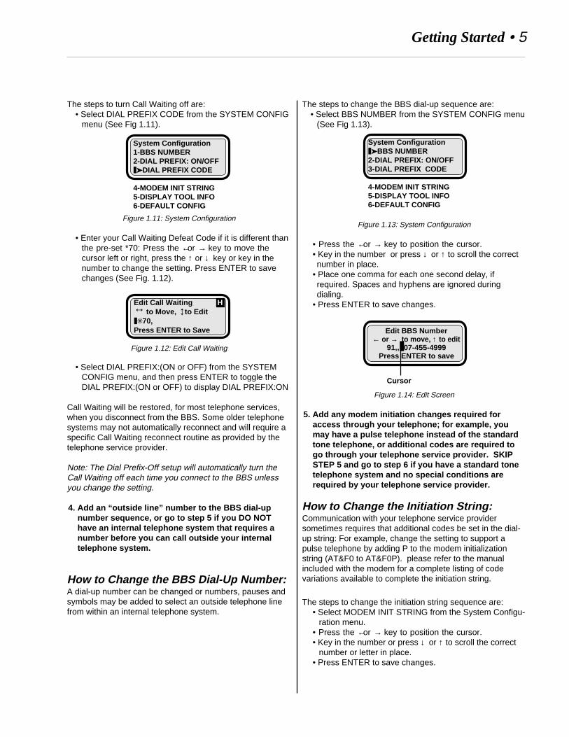
The steps to turn Call Waiting off are:• Select DIAL PREFIX CODE from the SYSTEM CONFIG
menu (See Fig 1.11).
Figure 1.11: System Configuration
• Enter your Call Waiting Defeat Code if it is different thanthe pre-set *70: Press the ← or → key to move thecursor left or right, press the ↑ or ↓ key or key in thenumber to change the setting. Press ENTER to savechanges (See Fig. 1.12).
Figure 1.12: Edit Call Waiting
• Select DIAL PREFIX:(ON or OFF) from the SYSTEMCONFIG menu, and then press ENTER to toggle theDIAL PREFIX:(ON or OFF) to display DIAL PREFIX:ON
Call Waiting will be restored, for most telephone services,when you disconnect from the BBS. Some older telephonesystems may not automatically reconnect and will require aspecific Call Waiting reconnect routine as provided by thetelephone service provider.
Note: The Dial Prefix-Off setup will automatically turn theCall Waiting off each time you connect to the BBS unlessyou change the setting.
4. Add an “outside line” number to the BBS dial-upnumber sequence, or go to step 5 if you DO NOThave an internal telephone system that requires anumber before you can call outside your internaltelephone system.
How to Change the BBS Dial-Up Number:A dial-up number can be changed or numbers, pauses andsymbols may be added to select an outside telephone linefrom within an internal telephone system.
↔
↔Edit Call Waiting H to Move, to Edit❚✳70,Press ENTER to Save
System Configuration1-BBS NUMBER2-DIAL PREFIX: ON/OFF❚➤DIAL PREFIX CODE
4-MODEM INIT STRING5-DISPLAY TOOL INFO6-DEFAULT CONFIG
The steps to change the BBS dial-up sequence are:• Select BBS NUMBER from the SYSTEM CONFIG menu
(See Fig 1.13).
Figure 1.13: System Configuration
• Press the ← or → key to position the cursor.• Key in the number or press ↓ or ↑ to scroll the correctnumber in place.
• Place one comma for each one second delay, ifrequired. Spaces and hyphens are ignored duringdialing.
• Press ENTER to save changes.
Figure 1.14: Edit Screen
5. Add any modem initiation changes required foraccess through your telephone; for example, youmay have a pulse telephone instead of the standardtone telephone, or additional codes are required togo through your telephone service provider. SKIPSTEP 5 and go to step 6 if you have a standard tonetelephone system and no special conditions arerequired by your telephone service provider.
How to Change the Initiation String:Communication with your telephone service providersometimes requires that additional codes be set in the dial-up string: For example, change the setting to support apulse telephone by adding P to the modem initializationstring (AT&F0 to AT&F0P). please refer to the manualincluded with the modem for a complete listing of codevariations available to complete the initiation string.
The steps to change the initiation string sequence are:• Select MODEM INIT STRING from the System Configu-
ration menu.• Press the ← or → key to position the cursor.• Key in the number or press ↓ or ↑ to scroll the correct
number or letter in place.• Press ENTER to save changes.
System Configuration❚➤BBS NUMBER2-DIAL PREFIX: ON/OFF3-DIAL PREFIX CODE
4-MODEM INIT STRING5-DISPLAY TOOL INFO6-DEFAULT CONFIG
Edit BBS Number← or → to move, ↑ to edit
91,,❚07-455-4999Press ENTER to save
Cursor
6 • Getting Started
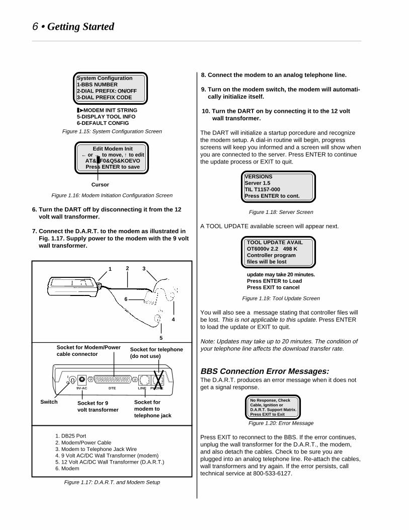
Figure 1.15: System Configuration Screen
Figure 1.16: Modem Initiation Configuration Screen
6. Turn the DART off by disconnecting it from the 12volt wall transformer.
7. Connect the D.A.R.T. to the modem as illustrated inFig. 1.17. Supply power to the modem with the 9 voltwall transformer.
1. DB25 Port2. Modem/Power Cable3. Modem to Telephone Jack Wire4. 9 Volt AC/DC Wall Transformer (modem)5. 12 Volt AC/DC Wall Transformer (D.A.R.T.)6. Modem
Figure 1.17: D.A.R.T. and Modem Setup
Edit Modem Init← or → to move, ↑ to edit
AT&❚F0&Q5&KOEVOPress ENTER to save
Cursor
6
1 2
5
3
4
I
O
9V-AC DTE LINE PHONE
Switch Socket for 9volt transformer
Socket for Modem/Powercable connector
Socket formodem totelephone jack
Socket for telephone(do not use)
VERSIONSServer 1.5TIL T1157-000Press ENTER to cont.
TOOL UPDATE AVAILOT6000v 2.2 498 KController programfiles will be lost
update may take 20 minutes.Press ENTER to LoadPress EXIT to cancel
No Response, CheckCable, Ignition orD.A.R.T. Support Matrix.Press EXIT to Exit
System Configuration1-BBS NUMBER2-DIAL PREFIX: ON/OFF3-DIAL PREFIX CODE
❚➤MODEM INIT STRING5-DISPLAY TOOL INFO6-DEFAULT CONFIG
8. Connect the modem to an analog telephone line.
9. Turn on the modem switch, the modem will automati-cally initialize itself.
10. Turn the DART on by connecting it to the 12 voltwall transformer.
The DART will initialize a startup porcedure and recognizethe modem setup. A dial-in routine will begin, progressscreens will keep you informed and a screen will show whenyou are connected to the server. Press ENTER to continuethe update process or EXIT to quit.
Figure 1.18: Server Screen
A TOOL UPDATE available screen will appear next.
Figure 1.19: Tool Update Screen
You will also see a message stating that controller files willbe lost. This is not applicable to this update. Press ENTERto load the update or EXIT to quit.
Note: Updates may take up to 20 minutes. The condition ofyour telephone line affects the download transfer rate.
BBS Connection Error Messages:The D.A.R.T. produces an error message when it does notget a signal response.
Figure 1.20: Error Message
Press EXIT to reconnect to the BBS. If the error continues,unplug the wall transformer for the D.A.R.T., the modem,and also detach the cables. Check to be sure you areplugged into an analog telephone line. Re-attach the cables,wall transformers and try again. If the error persists, calltechnical service at 800-533-6127.

Getting Started • 7
How to Update a D.A.R.T. Manual
As future updates to the D.A.R.T. operating system aremade available for download to your tool, the D.A.R.T.User’s Manual will also be be made available for downloadto your computer. Simply access the OTC World Wide Website located at http://www.otctools.com and click on theProduct Manuals icon to download an updated User’sManual. You may also order an updated User’s Manualthrough your SPX/OTC tool supplier.

8 • Reprogramming Procedures
How do I Update aControllerStep 1: Connect the D.A.R.T. to thevehicle controller to determine thecontroller part number.
1. From the Main Menu screen, press the ↓ key until the❚➤ icon points to VEHICLE ID, and then press ENTERto select.
Figure 2.2: Select Vehicle
2. From the Vehicle ID menu, select READ ENGINE ID #or READ TRANS ID #, and then press ENTER toselect.
Figure 2.3: Select Store ID Number
The DART will read and display the Controller Identificationnumber. Exit the ID screen and go to the next step.
3. From the Vehicle ID menu, select STORE ID #, andthen press ENTER to select.
Figure 2.4: Select Store ID Number
The tool will save the data into memory. Press EXIT twice toreturn to the Main Menu screen.
4. Detach the cable from the tool.
Main Menu:3- SKIM FUNCTIONS4- CUST PREFERENCE❚➤VEHICLE ID
↓
CONTINUED ON NEXT PAGE...
Vehicle ID:1- READ ENGINE ID #2- READ TRANS ID #❚➤STORE ID #
Vehicle ID:❚➤READ ENGINE ID #2- READ TRANS ID #3- STORE ID #
How to Update a ControllerAbout Cable SetupThe D.A.R.T. cable setup configuration requires one setupto connect the tool to the OTC Bulletin Board System (BBS)to download programming information and a second setupto connect the tool to the vehicle controller or Data LinkConnector (DLC). To determine which cable is required foryour application, Refer to Cable Connector Locations in theAppendix.
Chrysler software updates for engine or transmissioncontrollers can be performed with the D.A.R.T. But first,there are documentation and labeling issues that you mustbe aware of before you update a vehicle controller.
Required DocumentationUpdates to software for engine or transmission control-lers are published in Chrysler Technical ServiceBulletins (TSBs). A Chrysler Technical Service Bulletinmust specify that a control module update is requiredbefore you may reprogram any engine or transmissioncontroller. In addition, there may be laws that specifywhat documentation is required before you can repro-gram a vehicle controller.
Once the controller software is updated, you must place anAuthorized Software Update Label on the vehicle controllerand an Authorized Modification Label beside the VehicleEmission Component Information (VECI) label.
Additional vehicle component replacement–if required withthe controller update–is also specified on the same TSB. Itis important that the entire TSB be read and all require-ments carried out to ensure that all components of theupdate are completed.
To Get Technical Service Bulletins
Technical Service Bulletins (TSB) are prepared by theChrysler Corporation and then distributed to ChryslerDealerships. Your local Chrysler Dealership is your bestsource for TSBs that specifically address any drivabilityproblems and corrective actions. Additional sources are:
• Chrysler Training Publications• Service information resources such as OTC Drivability
TSB Manuals• Federal Government World Wide Web site located at
http://www.Fedworld.gov/cleanair/search.htm
Figure 2.1: Technical Service Bulletin

Reprogramming Procedures • 9
Step 2: Connect the D.A.R.T. to the BBS.
5. Attach the Modem/Power Cable to the DART DB25Port and to the Modem (see Fig. 2.5).
1. DB25 Port2. Modem/Power Cable3. Modem to Telephone Jack Wire4. 9 Volt AC/DC Wall Transformer (modem)5. 12 Volt AC/DC Wall Transformer (D.A.R.T.)6. Modem
Figure 2.5: D.A.R.T. and Modem Setup
6. Supply DC power (Item 5) to the D.A.R.T., as illus-trated.
The DART will initiate a Main Menu display when power issupplied.
Note: Call Waiting service—if you have this feature for yourtelephone line— should have been turned off when youregistered and updated your D.A.R.T. software. The DARTsetup for the Bulletin Board System (BBS) will automaticallyturn the call waiting off again until you finish communicatingwith the BBS.
7. Connect the D.A.R.T. to the modem as illustrated inFig. 2.5. Supply power to the modem with the 9 voltwall transformer: The modem will automaticallyinitialize itself, and then dial into the BBS.
Note: If there is an ERROR response, press EXIT and retry.If the error continues, unplug the wall transformers, themodem, and also detach the cables; reattach the cables,wall transformers and try again. If the error persists, calltechnical service at 800-533-6127.
The BBS will check the revision level of the D.A.R.T.software. It will notify you if there is an update and let youmake the choice if you want to automatically update theD.A.R.T. software. Press EXIT if you want to update at alater date.
6
1 2
5
3
4
Important: a D.A.R.T. update erases all controllerupdate files stored in the D.A.R.T. Directory List.
Note: There are no controller update files stored in the tool ifthis is the first time you are getting controller update filesfrom the BBS.
Figure 2.6: Warning Screen
Tool update time may vary significantly due to variations inthe telephone line quality.
8. The BBS will offer two options for submission ofcontroller update information, select one:• DIRECT PART NUMBER—Submit the controller part
number stored in memory to the BBS, or enter anumber manually (press ← or → to position thecursor, press ↓ to ↑ change the number).
• VEHICLE DESCRIPTION—Enter a vehicle descrip-tion to be submitted to the BBS.
Figure 2.7: Submit Options
If DIRECT PART NUMBER is selected: A screen to verifythe number or request additional vehicle option informationwill be displayed before the download program is initiated.
If VEHICLE DESCRIPTION is selected: A series of screenqueries will be displayed. An accurate response to eachquery is required.
When the BBS has completed the download, disconnect theD.A.R.T. from the modem.
Enter Part NumberXXXXXXXX
Press ENTER to load
Figure 2.8: DirectPart Number
Select: Model Year❚➤1994 1995 1996Select: Body Style
❚➤FJ11 JA LHSelect: Engine
❚➤3.3L V6(SFI) N-S GAS 3.3L V6(SFI) N-S FLEX 3.5L V6(SFI) 24V GAS
Figure 2.9: VehicleDescription
Select: Options❚➤50 STATE AUTO HI SPEED 50 STATE AUTO NORMAL 93-95LH ALL ENGINES
Tool update available.OTxxxx v.xx.x xxxxkController program fileswill be lost. Update will
take up to 20 minutes.Press ENTER to loadPress EXIT to cancel
Part Selection❚➤DIRECT PART NUMBER VEHICLE DESCRIPTION

10 • Reprogramming Procedures
Step 4: Complete any steps remaining inthe TSB.
Step 5: Attach the labels–as required bylaw–to the vehicle and to thereprogrammed controller.
Authorized Software Update Label Requirements:Each time a software update is made to a vehicle, you mustenter the information required onto the Authorized SoftwareUpdate label and attach this label onto the vehicle asdirected. Important: The Authorized Software Updatelabel is required by law.
a. Fill out the Authorized Software Update label with thefollowing information:• The part number of the updated controller;• Your Dealer Code or D.A.R.T. serial number;• The date
.
Figure 2.13: Authorized Software Update Label
b. Attach the label on top of the controller and place theaccompanying clear sticker over the top of the label.
Authorized Modification Label Requirements:Each time a software update is made to a vehicle, you mustenter the update data required onto the Authorized Modifi-cation label and attach this label onto the vehicle asdirected. Important: The Authorized Modification label isrequired by law.
a. Fill out the Authorized Modification Label with thefollowing information:• The part number of the updated controller;• The change authority (TSB number);• Your Dealer Code or D.A.R.T. serial number;• The date.
Figure 2.14: Authorized Modification Label
b. Attach the label on the vehicle near the EmissionComponent Information (VECI) label.
Step 3: Reconnect the D.A.R.T. to thevehicle controller.
9. The D.A.R.T. will initialize and display the Main Menuscreen. Press the ↓ key until the ❚➤ icon points toREPROGRAM VEHICLE, and then press ENTER toselect.
Figure 2.10: Reprogram Vehicle
10. Select REPROGRAM ENGINE or REPROGRAMTRANS from the Reprogram Vehicle menu.
Figure 2.11: Select Reprogram
Additional transmission choices (such as EATX2, EATX3 orEATX3 MMC) may be offered. Select the appropriateconfiguration, and then respond to any directions displayedas the D.A.R.T. guides you through the reprogrammingprocess.
Important: The vehicle computer/controller may bedamaged beyond repair if a power cable or adaptercable is removed during the reprogramming step.
As the D.A.R.T. downloads the selected programming file tothe vehicle computer/controller, follow the instructionsdisplayed on-screen.
If the computer/controller programming is current or if theprogram is invalid for the vehicle, the tool will immediatelystop the procedure before any change takes place.
About the Directory List:Previously downloaded programs are stored in D.A.R.T.memory and may be used if appropriate. If, during adownload, the directory list is filled, you will have to delete afile to make room for the new file, follow the on-screenprompts.
To re-use a file, select DIRECTORY LIST from the Repro-gram Vehicle menu, and choose the proper program.
Figure 2.12: Select File
Main Menu:❚➤REPROGRAM VEHICLE2- TROUBLE CODES3- SKIM FUNCTIONS
↓
Reprogram Vehicle:❚➤REPROGRAM ENGINE2- REPROGRAM TRANS3- DIRECTORY LIST
↓
Directory List:❚➤XXXXXXXXX2- XXXXXXXXX3- XXXXXXXXX
↓

Reprogramming Procedures • 11
Diagnostic testing is one of the functions performed by thevehicle management system. The Powertrain ControlModule (PCM) monitors the system and performs activitytests when passive tests fail. A Diagnostic Trouble Code(DTC) is recorded in the vehicle computer memory if thePCM determines that a component may have failed.
The D.A.R.T. reads and displays the DTCs recorded in thePCM.
How to Connect the Cable1. Refer to Cable Connector Locations in the Appendix
to determine which cables are required to connectthe D.A.R.T. to the vehicle and to determine wherethe connector is located on the vehicle.
2. Connect the cable to the tool and to the vehicleconnector.
3. Supply power to the tool, the program will automati-cally initialize and identify the vehicle.
Power is supplied to the D.A.R.T. when the cable isconnected to the DLC or when the cable battery clamp (if soequipped) is connected to the battery.
How to Read DiagnosticTrouble Codes1. From the D.A.R.T. Main Menu , select TROUBLE
CODES or GENERIC OBD II.
Select TROUBLE CODES to see DTCs for all vehiclesystems. Select GENERIC OBD II to see DTCs for theEmissions System.
Figure 2.15: Main Menu
2. Select a vehicle system to view if you selectedTROUBLE CODES.
Figure 2.16: Vehicle Systems
3. From the DTC menu, Select your task choice.
FIGURE 2.17: Generic OBDII DTC Menu
REVIEW CODES: Display the DTCs recorded in thevehicle controller. Press the ↑ or ↓ key to position thecode to the top of the list, press ENTER to see the codedescription.CLEAR CODES: Select to clear (erase) all DTCs fromthe vehicle controller memory. This will clear all OBD IIdata, including readiness status.
Figure 2.18: Trouble Code Menu
ACTIVE DTCs: Display the DTCs recorded in the vehiclecontroller.ONE TRIP DTCs: Display the DTCs recorded after asingle trip. Many DTCs are not considered to be aproblem unless they re-occur during successive trips.ERASE DTCs: Select to clear (erase) all DTCs from thevehicle controller memory.
4. Clear (Erase) DTCs after the repair is completed.
Main Menu:1- REPROGRAM VEHICLE2- GENERIC OBD II❚➤TROUBLE CODES
↓
About Diagnostic Trouble Codes
DTC Review Press:❚➤REVIEW CODES2- CLEAR CODES
DTC Menu❚➤ACTIVE DTCs2- ONE TRIP DTCs3- ERASE DTCs
Select System:1- ENGINE2- TRANSMISSION❚➤BODY
↓

12 • Reprogramming Procedures
The Sentry Key Immobilizer System (SKIS) is a Chrysleroption designed to deter vehicle theft. Two importantcomponents of the SKIS are the Sentry ignition key and theSentry Key Immobilizer Module (SKIM). The immobilizermodule prevents the vehicle from starting until it is disabledwith a signal transmitted from a valid ignition key. The SKIMmaintains ignition key integrity by “remembering” each keyprogrammed for the vehicle.
The D.A.R.T. may be used to:• Add up to eight additional keys to SKIM memory;• program a set of new keys into SKIM memory;• if a key is lost, program the SKIM to erase memory forall of the keys programmed for the vehicle;
• reprogram existing keys into SKIM memory.
How to Connect the Cable1. Connect J1962 cable to the D.A.R.T. and to the
vehicle Data Link Connector located under the dash.
Figure 2.19: Data Link Connector Cable Setup
Power is supplied through the DLC to the D.A.R.T.: TheD.A.R.T. program will automatically initialize and identify thevehicle.
More about ProgrammingSentry KeysA Personal Identification Number (PIN) issued to the vehicleowner by the Chrysler Dealer when the vehicle waspurchased will be required before the SKIM program can beactivated. If the PIN is unavailable, contact the Chryslerdealer from whom the car was purchased. You will berequired to supply the Vehicle Identification Number (VIN) toreceive the PIN.
How to Program Keys
1. Select SKIM FUNCTIONS from the Main Menu , andthen press ENTER.
2. Place a mechanically cut Sentry ignition key in thevehicle ignition.
3. Select PROGRAM KEY(S) from the SKIM Functionmenu, and then press ENTER.
4. Enter the vehicle owner’s PIN, and then pressENTER.
5. Verify that the PIN number is correct (YES) or re-enter if the PIN number is wrong (NO). Follow the on-screen prompts to complete the task.
How to Erase Keys
1. Select SKIM FUNCTIONS from the Main Menu, andthen press ENTER.
2. Place a mechanically cut Sentry ignition key in thevehicle ignition.
3. Select ERASE ALL KEYS from the SKIM Functionmenu, and then press ENTER. Select YES to verifythat you want to erase a key, or select NO to quit.
4. Enter the vehicle owner’s PIN, and then pressENTER.
5. Verify that the PIN number is correct (YES) or re-enter if the PIN number is wrong (NO). Follow the on-screen prompts to complete the task.
6. To reprogram erased keys, follow the How to Pro-gram Keys procedure.
How to Program the Sentry Key
SKIM Function❚➤PROGRAM KEY(S)2- ERASE KEYS
Figure 2.20: Program Keys
SKIM Function1- PROGRAM KEY(S)❚➤ERASE ALL KEYS
Figure 2.21: Erase All Keys

Reprogramming Procedures • 13
About Customer Preferences
Customer Preferences are vehicle options that may betoggled or set through the vehicle controller.
How to Connect the Cable1. Refer to Cable Connections Locations in Appendix to
determine which cables are required to connect theD.A.R.T. to the vehicle and to determine where theconnector is located on the vehicle.
2. Connect the cable to the tool and to the vehicleconnector.
3. Supply power to the tool, the program will automati-cally initialize and identify the vehicle.
Power is supplied to the D.A.R.T. when the cable isconnected to the DLC or when the cable battery clamp (if soequipped) is connected to the battery.
How to Set CustomerPreferences1. Select CUSTOMER PREFERENCES from the D.A.R.T.
Main Menu .
The tool will automatically query the diagnostic protocol todetermine which Customer Preferences are available on thevehicle controller.
2. Select the Customer Preferences you wish to change.
Notes:• All Customer Preferences shown as available for the
vehicle controller may not be installed options; i.e.,automatic door locks programming is shown in thecontroller but the automatic door locks option was notpurchased by the vehicle owner.
• All vehicle controller systems are not equipped to turnoptions on or off.
Customer Preference Descriptions
• AUTO DOOR LOCKS ................. Enable/DisableEnable or disable the switch that locks the doors aftera vehicle reaches speed of 15 mph.
• SPEED CHIME ............................ Enable/DisableEnable or disable the switch that sounds a chimewhen a factory-set speed is exceeded.
• LOW FUEL CHIME ..................... Enable/DisableEnable or disable the switch that sounds a chimewhen fuel is low.
• TURN SIGNAL ............................ Enable/DisableEnable or disable the switch that sounds a chime if aturn signal remains on too long.
• ILLUMINATED ENTRY ............... Enable/DisableEnable or disable the switch that turns the Interiorlights on when the door handle is lifted.
• AUTO HEAD LAMP .................... Enable/DisableEnable or disable the switch that turns the headlightson when windshield wipers are turned on.
• RKE HORN CHIRP ..................... Enable/DisableTurn the Remote Keyless Entry horn “chirp” on or off.
• RKE PANIC MODE ..................... Enable/DisableTurn the Remote Keyless Entry Panic Mode on or off.
• RKE DOOR UNLOCK ................. Press Once/TwiceSet the Remote Keyless Entry to unlock all doorswhen the remote transmitter is clicked once or twice.
• PROGRAM RKE ......................... Program transmitterSelect remote transmitter 1 or 2 for reprogramming.
• CHANGE COUNTRY .................. Select CountryEnable vehicle settings that are specific to thecountry the vehicle is driven in.
• CHANGE EQUIPMENTIdentify the equipment or vehicle settings for arecently installed controller.- AIR BAG ............................. Yes/No
Identify if equipped with an air bag.- DRIVE .................................. Right/Left
Identify if equipped with Right or Left Drive.- FUEL UNITS ....................... US/Imperial
Identify if fuel to be displayed in US or Imperialgallons.
- POLICE ............................... Yes/NoIdentify if vehicle is equipped as a Police vehicle
- FOG LAMPS ....................... Yes/NoIdentify if vehicle is equipped with fog lamps.
- COMPASS MINI TRIP ......... Yes/NoIdentify if vehicle is equipped with the CompassMini Trip option.
• HORN CHIRP TIME .................... 20ms/40msSet the horn “chirp” to a shorter or longer duration.

14 • Reprogramming Procedures
Miscellaneous TestsMiscellaneous test options are generally service tests or ameans of setting adjustments to vehicle components. Referto each option description to see if it may apply to yourvehicle repair.
Additional tests or settings will be added in the future andcan be downloaded to the D.A.R.T. when you connect to theBBS.
Select MISC. FUNCTIONS from the DART Main Menu tosee miscellaneous tests available.
Note: All tests may not be applicable to all vehicles.
About Pinion FactorThe Pinion Factor option sets the pinion factor in theTransmission Control Module memory. Use this feature iftire size or a control module is changed.
How to Set Pinion Factor:1. Select PINION FACTOR from the Misc. Functions
menu.
2. Select the tire size, and then press ENTER to set thepinion factor into the controller memory.
About Clutch Volume IndexThe Clutch Volume Index option shows the vehicle actualclutch volume values. If the battery electrical feed isdisconnected from the controller, the learned clutch fillvolumes will be erased and initial values will be substituted.The transmission may shift gears somewhat harshly untilthe vehicle computer relearns optimum clutch fill volumes.
How to see Clutch Volume Index:
Select CLUTCH VOL INDEX from the Misc. Functionsmenu. The DART will show the Clutch Volume Values.

Reprogramming Procedures • 15
About Vehicle IdentificationAccurate identification of the vehicle and part numberidentification of the controllers installed on the vehicle isimportant to make sure the correct software update for eachcomponent is correctly identified for programming updates.The Vehicle Identification options read and store thenecessary part numbers for each controller.
Figure 2.22: Vehicle Identification
How to Identify a VehicleSelect VEHICLE INFO from the Vehicle ID menu to see adescription of the vehicle.
Figure 2.23: Vehicle Description
How to Read an EngineIdentification NumberSelect READ ENGINE ID # from the Vehicle ID menu to seethe part number for the engine controller.
Figure 2.24: Engine Controller Part Number
Exit and select STORE ID # if you want to save the engineinformation into D.A.R.T. memory.
1997 NS/GS3.3L
SBEC3+Press EXIT
Vehicle ID1-READ ENGINE ID#2-READ TRANS ID#3-STORE ID#
4-VEHICLE INFO
Engine ID#04727205AG
READ FROM VEHICLEPress EXIT
How to Read aTransmission IdentificationNumberSelect READ TRANS ID# from the Vehicle ID menu to seethe part number for the transmission controller.
Figure 2.25: Transmission Controller Part Number
Exit and select STORE ID# if you want to save the engineinformation into D.A.R.T. memory.
How to Save anIdentification Number intoMemorySelect STORE ID# from the Vehicle ID menu to save thepart number for the controller read.
Figure 2.26: Store ID Number
Transmission ID#04606485
READ FROM VEHICLEPress EXIT
Transmission ID#04606485
SAVED IN DARTPress EXIT
16 • Reprogramming Procedures
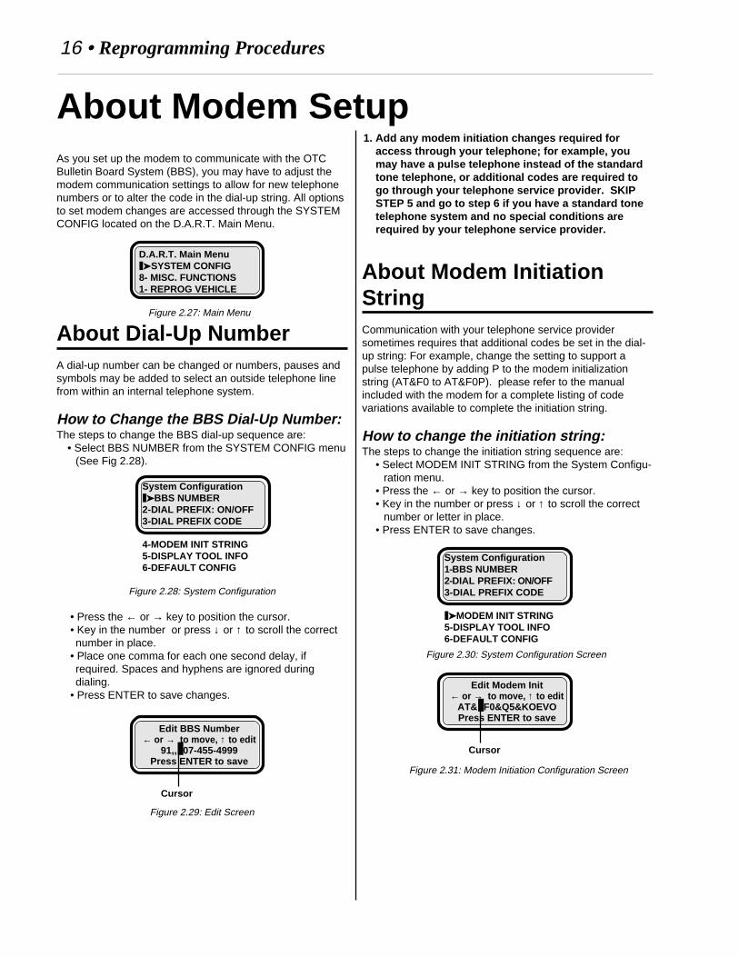
As you set up the modem to communicate with the OTCBulletin Board System (BBS), you may have to adjust themodem communication settings to allow for new telephonenumbers or to alter the code in the dial-up string. All optionsto set modem changes are accessed through the SYSTEMCONFIG located on the D.A.R.T. Main Menu.
About Dial-Up NumberA dial-up number can be changed or numbers, pauses andsymbols may be added to select an outside telephone linefrom within an internal telephone system.
How to Change the BBS Dial-Up Number:The steps to change the BBS dial-up sequence are:
• Select BBS NUMBER from the SYSTEM CONFIG menu(See Fig 2.28).
Figure 2.28: System Configuration
• Press the ← or → key to position the cursor.• Key in the number or press ↓ or ↑ to scroll the correctnumber in place.
• Place one comma for each one second delay, ifrequired. Spaces and hyphens are ignored duringdialing.
• Press ENTER to save changes.
Figure 2.29: Edit Screen
D.A.R.T. Main Menu❚➤SYSTEM CONFIG8- MISC. FUNCTIONS1- REPROG VEHICLE
Figure 2.27: Main Menu
1. Add any modem initiation changes required foraccess through your telephone; for example, youmay have a pulse telephone instead of the standardtone telephone, or additional codes are required togo through your telephone service provider. SKIPSTEP 5 and go to step 6 if you have a standard tonetelephone system and no special conditions arerequired by your telephone service provider.
About Modem InitiationStringCommunication with your telephone service providersometimes requires that additional codes be set in the dial-up string: For example, change the setting to support apulse telephone by adding P to the modem initializationstring (AT&F0 to AT&F0P). please refer to the manualincluded with the modem for a complete listing of codevariations available to complete the initiation string.
How to change the initiation string:The steps to change the initiation string sequence are:
• Select MODEM INIT STRING from the System Configu-ration menu.
• Press the ← or → key to position the cursor.• Key in the number or press ↓ or ↑ to scroll the correct
number or letter in place.• Press ENTER to save changes.
About Modem Setup
Edit BBS Number← or → to move, ↑ to edit
91,,❚07-455-4999Press ENTER to save
Cursor
System Configuration❚➤BBS NUMBER2-DIAL PREFIX: ON/OFF3-DIAL PREFIX CODE
4-MODEM INIT STRING5-DISPLAY TOOL INFO6-DEFAULT CONFIG
System Configuration1-BBS NUMBER2-DIAL PREFIX: ON/OFF3-DIAL PREFIX CODE
❚➤MODEM INIT STRING5-DISPLAY TOOL INFO6-DEFAULT CONFIG
Edit Modem Init← or → to move, ↑ to edit
AT&❚F0&Q5&KOEVOPress ENTER to save
Cursor
Figure 2.30: System Configuration Screen
Figure 2.31: Modem Initiation Configuration Screen
Reprogramming Procedures • 17
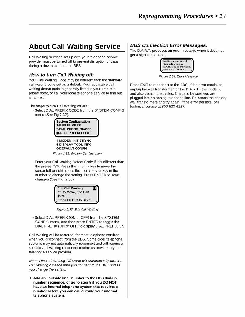
About Call Waiting ServiceCall Waiting services set up with your telephone serviceprovider must be turned off to prevent disruption of dataduring a download from the BBS.
How to turn Call Waiting off:Your Call Waiting Code may be different than the standardcall waiting code set as a default. Your applicable callwaiting defeat code is generally listed in your area tele-phone book, or call your local telephone service to find outwhat it is.
The steps to turn Call Waiting off are:• Select DIAL PREFIX CODE from the SYSTEM CONFIG
menu (See Fig 2.32).
Figure 2.32: System Configuration
• Enter your Call Waiting Defeat Code if it is different thanthe pre-set *70: Press the ← or → key to move thecursor left or right, press the ↑ or ↓ key or key in thenumber to change the setting. Press ENTER to savechanges (See Fig. 2.33).
Figure 2.33: Edit Call Waiting
• Select DIAL PREFIX:(ON or OFF) from the SYSTEMCONFIG menu, and then press ENTER to toggle theDIAL PREFIX:(ON or OFF) to display DIAL PREFIX:ON
Call Waiting will be restored, for most telephone services,when you disconnect from the BBS. Some older telephonesystems may not automatically reconnect and will require aspecific Call Waiting reconnect routine as provided by thetelephone service provider.
Note: The Call Waiting-Off setup will automatically turn theCall Waiting off each time you connect to the BBS unlessyou change the setting.
1. Add an “outside line” number to the BBS dial-upnumber sequence, or go to step 5 if you DO NOThave an internal telephone system that requires anumber before you can call outside your internaltelephone system.
↔
↔Edit Call Waiting H to Move, to Edit❚✳70,Press ENTER to Save
System Configuration1-BBS NUMBER2-DIAL PREFIX: ON/OFF❚➤DIAL PREFIX CODE
4-MODEM INIT STRING5-DISPLAY TOOL INFO6-DEFAULT CONFIG
BBS Connection Error Messages:The D.A.R.T. produces an error message when it does notget a signal response.
Figure 2.34: Error Message
Press EXIT to reconnect to the BBS. If the error continues,unplug the wall transformer for the D.A.R.T., the modem,and also detach the cables. Check to be sure you areplugged into an analog telephone line. Re-attach the cables,wall transformers and try again. If the error persists, calltechnical service at 800-533-6127.
No Response, CheckCable, Ignition orD.A.R.T. Support Matrix.Press EXIT to Exit

18 • Appendixes
1-REPROG VEHICLE1-REPROG ENGINE2-REPROG TRANS2-DIRECTORY LIST3-DELETE FILE
2-GENERIC OBD II1-REVIEW CODES2-CLEAR CODES
3-TROUBLE CODES(ENGINE, TRANSMISSION, BODY, SUSPENSION, CHASSIS,BRAKES, PASSIVE RESTRAINT, THEFT ALARM)1-ACTIVE DTCS
2-ONE TRIP DTCS
3-ERASE DTCS
4-SKIM FUNCTIONS1-PROGRAM KEY(S)2-ERASE ALL KEYS
5-CUSTOMER PREFERENCE1-AUTO DOOR LOCKS2-SPEED CHIME3-LOW FUEL CHIME4-TURN SIGNAL5-ILLUMINATED ENTRY6-AUTO HEAD LAMP7-RKE HORN CHIRP8-RKE PANIC MODE9-RKE DOOR UNLOCK10-PROGRAM RKE11-CHANGE COUNTRY12-CHANGE EQUIPMENT
1-AIR BAG2-DRIVE3-FUEL UNITS4-POLICE5-FOG LAMPS6-COMPASS MINI TRIP
13-HORN CHIRP TIME6-VEHICLE ID
1-READ ENGINE ID#2-READ TRANS ID#3-STORE ID#4-VEHICLE INFORMATION
7-SYSTEM CONFIG1-BBS NUMBER2-DIAL PREFIX: ON/OFF3-DIAL PREFIX CODE4-MODEM INIT STRING5-DISPLAY TOOL INFO6-DEFAULT CONFIG
8-MISC FUNCTIONS1-PINION FACTOR2-CLUTCH VOL. INDEX
Note: All vehicles may not support all of the menu optionillustrated
D.A.R.T. Menu ViewREPROG(ram) VEHICLE
The REPROGRAM VEHICLE option makes reprogrammingoptions available for the engine and transmission control-lers.
REPROG(ram) ENGINE
Select REPROG ENGINE when you have the correctcontroller file in the D.A.R.T. memory. During the setupprocess, the appropriate files that are available for repro-gramming the selected controller are displayed. This optionguides you through the reprogram steps, simply respond toany questions or directions displayed on-screen.
Apply an Authorized Software Update label and an Autho-rized Modification Label to the controller when reprogram-ming is completed.
REPROGRAM TRANSM(ission)
Select REPROGRAM TRANSM when you have the correctcontroller file in the D.A.R.T. memory. During the setupprocess, the appropriate files that are available for repro-gramming the selected controller are displayed. This optionguides you through the reprogram steps, simply respond toany questions or directions displayed on-screen.
Apply an Authorized Software Update label and an Autho-rized Modification Label to the controller when reprogram-ming is completed.
DIRECTORY LIST
Select DIRECTORY LIST to see a listing of controllerupdate programs stored in the D.A.R.T. memory. A programfrom this list will be selected by the DART during thereprogramming process.
ERASE FILE
Select the file to be erased from the list.
GENERIC OBD II
The GENERIC OBD II option reads and displays theemission Diagnostic Trouble Codes (DTCs) recorded in avehicle Power Control Module (PCM). This option isavailable for all OBD II compliant vehicles sold in the USA.
REVIEW DTCs
Select REVIEW DTCs to see the Diagnostic Trouble Codessaved in the PCM.

Appendixes• 19
CLEAR DTCs
All DTCs will be deleted (erased) from the PCM.
TROUBLE CODES
The TROUBLE CODES option reads and displays theDiagnostic Trouble Codes (DTCs) recorded in a controllermodule. Select the controller module (Engine, Transmission,ABS, SRS, Body, etc.) you want to check, and then selectwhether you want to see active DTCs or One Trip DTCs.
Note: Trouble Codes may also be labeled as Fault Codes.
ACTIVE DTCs
Select ACTIVE DTCs to display the codes saved in thePCM. Codes received are displayed as a number. Press theENTER key to see a description of the code positioned onthe top line of the display screen. Press the ↑ key to positionany other codes onto the top line for display.
ONE TRIP DTCs
Select the ONE TRIP DTC option to see codes saved due toa fault that occurred at least once. Many faults are notsaved as a DTC until they have occurred over multiple tripsbecause one or two occurrences do not necessary indicatea true fault that should set a DTC.
ERASE DTCs
All DTCs will be deleted (erased) from the PCM.
SKIM FUNCTIONS
Select the D.A.R.T. SKIM FUNCTION if the Sentry KeyImmobilizer Module (SKIM) must be reprogrammed for newkeys or if additional Sentry ignition keys need to be pro-grammed into SKIM memory.
PROGRAM KEY(S)
The PROGRAM KEY(S) selection initiates a programmingprocess that programs keys into the SKIM system.
ERASE ALL KEYS
Select ERASE ALL KEYS to erase SKIM memory
CUSTOMER PREFERENCES
Select CUSTOMER PREFERENCES to set or to turnvehicle options on or off through the vehicle controller.Some Customer Preferences may offer additional program-ming options.
VEHICLE ID(entification)
Select VEHICLE ID to read or save the controller identifica-tion number into the D.A.R.T. memory.
READ ENGINE ID(entification)#
Select READ ENGINE ID# to read and display the enginecontroller identification number.
READ TRANS(mission)ID(entification)#
Select READ TRANS ID# to read and display the transmis-sion controller identification number.
STORE ID(entification)#
Select STORE ID# to save the controller identificationnumber in D.A.R.T. memory.
VEHICLE INFO(rmation)
Select VEHICLE INFO to display the vehicle description.
SYSTEM CONF(iguration)
Select SYSTEM CONFIG to set up or to change the factorysettings for the BBS communication program.
BBS NUMBER
Select BBS NUMBER to change the number used to dialinto the Bulletin Board.

20 • Appendixes
DIAL PREFIX: ON/OFF
The Call Waiting feature provided by your telephone servicecan disrupt data during a file download. Call Waiting mustbe turned off during the time the D.A.R.T. is communicatingwith the bulletin board.
Select DIAL PREFIX: ON and press the number key 2 orpress ENTER to toggle the Call Waiting off.
This feature is generally restored when you disconnect andremove the D.A.R.T. from the modem setup. Some oldertelephone systems may not automatically reconnect and willrequire a specific Call Waiting reconnect routine as providedby the telephone service provider.
DIAL PREFIX CODE
Select DIAL PREFIX CODE to enter your Call WaitingDefeat Code. Your applicable defeat code is listed in yourarea telephone book, or call your local telephone service.
MODEM INIT(ialize) STRING
Select MODEM INIT STRING to change the setting for themodem dial-up routine.
DISPLAY TOOL INFO(rmation)
Select DISPLAY TOOL INFO to view software revision dateand revision number.
DEFAULT CONF(iguration)
Select DEFAULT CONFIG to restore the current communi-cation settings back to the original factory communicationsettings.
MISC(ellaneous) FUNCTIONS
Additional tests and settings are accessed through theMiscellaneous option.
PINION FACTOR
Select PINION FACTOR to set the pinion factor in theTransmission Control Module memory. Use this option if tiresize or a control module is changed.
CLUTCH VOL(ume) INDEX
The CLUTCH VOL INDEX option shows the vehicle actualclutch volume values. If the battery electrical feed isdisconnected from the controller, the learned clutch fillvolumes will be erased and initial values will be substituted.
Appendixes• 21
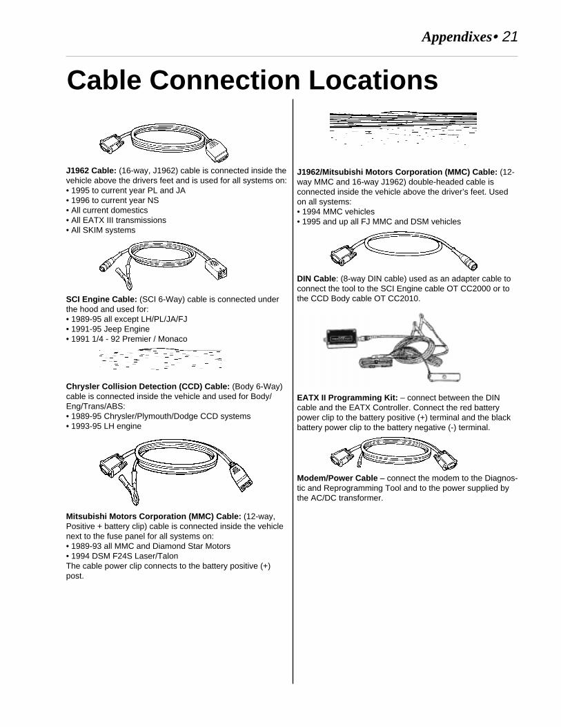
Cable Connection Locations
J1962 Cable: (16-way, J1962) cable is connected inside thevehicle above the drivers feet and is used for all systems on:• 1995 to current year PL and JA• 1996 to current year NS• All current domestics• All EATX III transmissions• All SKIM systems
SCI Engine Cable: (SCI 6-Way) cable is connected underthe hood and used for:• 1989-95 all except LH/PL/JA/FJ• 1991-95 Jeep Engine• 1991 1/4 - 92 Premier / Monaco
Chrysler Collision Detection (CCD) Cable: (Body 6-Way)cable is connected inside the vehicle and used for Body/Eng/Trans/ABS:• 1989-95 Chrysler/Plymouth/Dodge CCD systems• 1993-95 LH engine
Mitsubishi Motors Corporation (MMC) Cable: (12-way,Positive + battery clip) cable is connected inside the vehiclenext to the fuse panel for all systems on:• 1989-93 all MMC and Diamond Star Motors• 1994 DSM F24S Laser/TalonThe cable power clip connects to the battery positive (+)post.
J1962/Mitsubishi Motors Corporation (MMC) Cable: (12-way MMC and 16-way J1962) double-headed cable isconnected inside the vehicle above the driver’s feet. Usedon all systems:• 1994 MMC vehicles• 1995 and up all FJ MMC and DSM vehicles
DIN Cable : (8-way DIN cable) used as an adapter cable toconnect the tool to the SCI Engine cable OT CC2000 or tothe CCD Body cable OT CC2010.
EATX II Programming Kit: – connect between the DINcable and the EATX Controller. Connect the red batterypower clip to the battery positive (+) terminal and the blackbattery power clip to the battery negative (-) terminal.
Modem/Power Cable – connect the modem to the Diagnos-tic and Reprogramming Tool and to the power supplied bythe AC/DC transformer.

22 • Appendixes
Body Platform DesignationsBody Platform Vehicle LineAA .................................... ACCLAIMAA .................................... LEBARONAA .................................... SPIRITAA .................................... SPIRIT (MEX)AB .................................... B-150AB .................................... B-250AB .................................... B-350AB .................................... RAM 150AB .................................... RAM 250AB .................................... RAM 350AB .................................... RAM B-250AB .................................... RAM B-350AB .................................... RAM VAN 1500AB .................................... RAM VAN 2500AB .................................... RAM VAN 3500AB .................................... RAM WAGON 1500AB .................................... RAM WAGON 2500AB .................................... RAM WAGON 3500AC .................................... DYNASTYAC .................................... NEW YORKERAD .................................... POWER RAM 100AD .................................... POWER RAM 150AD .................................... POWER RAM 250AD .................................... POWER RAM 350AD .................................... RAM 100 4X2AD .................................... RAM 150 4X2AD .................................... RAM 250 4X2AD .................................... RAM 350 4X2AD .................................... RAMCHARGER 4X2AD .................................... RAMCHARGER 4X4AG .................................... DAYTONAAH .................................... LANCERAH .................................... LEBARONAJ ..................................... LEBARONAK .................................... ARIESAK .................................... RELIANTAL ..................................... HORIZONAL ..................................... OMNIAN .................................... DAKOTA 4X2AN .................................... DAKOTA 4X4AP .................................... SHADOWAP .................................... SUNDANCEAQ .................................... TCAS .................................... CARAVANAS .................................... GRAND CARAVANAS .................................... GRAND VOYAGERAS .................................... INCOMPLETE VEHAS .................................... MINI-VANAS .................................... RAM MINI-VANAS .................................... TOWN & COUNTRYAS .................................... VOYAGERAY .................................... IMPERIALAY .................................... NEW YORKERB1 ..................................... COLTB2 ..................................... COLTB2 ..................................... COLT (CANADA)B2 ..................................... SUMMITB3 ..................................... COLT
B3 ..................................... SUMMITB3 ..................................... VISTAB4 ..................................... D-50B4 ..................................... D-50 4X2B4 ..................................... D-50 4X4B7 ..................................... STEALTHB8 ..................................... SUMMITB8 ..................................... VISTAB9 ..................................... COLT (CANADA)B9 ..................................... SUMMITB9 ..................................... SUMMIT FWDBB .................................... MONACOBB .................................... PREMIERBD .................................... LASERBD .................................... TALONBR .................................... RAM 1500 4X2BR .................................... RAM 1500 4X4BR .................................... RAM 2500 4X2BR .................................... RAM 2500 4X4BR .................................... RAM 3500 4X2BR .................................... RAM 3500 4X4DN .................................... DURANGOFJ ..................................... AVENGERFJ ..................................... SEBRINGFJ ..................................... TALONJA ..................................... BREEZEJA ..................................... CIRRUSJA ..................................... STRATUSJX ..................................... SEBRINGLA ..................................... COLT (CANADA)LH..................................... CONCORDELH..................................... INTREPIDLH..................................... LHSLH..................................... NEW YORKERLH..................................... VISIONMJ .................................... COMANCHENF .................................... VISTANS .................................... CARAVANNS .................................... GRAND CARAVANNS .................................... GRAND VOYAGERNS .................................... TOWN & COUNTRYNS .................................... VOYAGERPL ..................................... NEONPL ..................................... NEON (MEXICO)PR .................................... PROWLERSJ ..................................... GRAND WAGONEERSJ ..................................... RAIDERSR .................................... VIPERSR .................................... VIPER (EUROPE)TJ ..................................... WRANGLERXJ ..................................... CHEROKEEXJ ..................................... CHEROKEE (RHD)XJ ..................................... WAGONEERYD .................................... CONQUESTYJ ..................................... WRANGLERZJ ..................................... GRAND CHEROKEEZJ ..................................... GRAND WAGONEER
Body Platform Vehicle Line

Appendixes• 23
A
ACTIVE DTCs 11, 19arrow keys 2, 3Authorized Modification Label 10, 18Authorized Software Update label 10, 18AUTO DOOR LOCKS 13AUTO HEAD LAMP 13
B
BBS NUMBER 19Body 22Body Platform Designations 22, 23Bulletin Board System (BBS), OTC 8, 16
C
Cable Connection Locations 21Cable Setup 3, 8Call Waiting 17, 20Call Waiting Defeat Code 20CHANGE COUNTRY 13CHANGE EQUIPMENT 13
Air Bag 13Compass Minitrip 13Drive 13Fog Lamps 13Fuel Units 13Police 13
Chrysler Collision Detection (CCD) Body Cable 21CLEAR CODES 11CLEAR DTCs 19CLUTCH VOL INDEX 20Clutch Volume Index 14Cursor 3Customer Preference Descriptions 13CUSTOMER PREFERENCES 13, 19Customer Preferences
Reset 2
D
D.A.R.T. Basics 2Data Link Connector (DLC) 3, 8, 12DB25 Port 2, 9DEFAULT CONFIG 20Diagnostic and Reprogramming Tool (D.A.R.T.) 2Diagnostic Trouble Code (DTC) 11Diagnostic Trouble Code Reader 2Diagnostic Trouble Codes (DTC) 18, 19DIAL PREFIX CODE 20dial-up number 16DIN Cable 21
DIRECT PART NUMBER 9DIRECTORY LIST 18directory list 9, 10DISPLAY TOOL INFO 20Display Window 2
E
EATX II Programming Kit 21ENTER key 2ERASE ALL KEYS 19ERASE DTCs 11, 19ERASE FILE 18error message 3EXIT keys 2
F
F1/F2 keys 2
G
GENERIC OBD II 11, 18
H
HELP key 2, 3HORN CHIRP TIME 13
I
icons 3icons, program 3
arrow 3Cursor 3HELP key 3
ILLUMINATED ENTRY 13
J
J1962 Cable 21J1962/Mitsubishi Motors Corporation (MMC) Cable 21
K
Keypad 2ENTER keys 2EXIT keys 2F1/F2 keys 2HELP key 2LEFT/RIGHT arrow keys 2RECORD key 2UP/DOWN arrow keys 2
Index

24 • Appendixes
L
LabelAuthorized Modification 10, 18Authorized Software Update 10, 18Emission Component Information 10
LEFT/RIGHT arrow keys 2Locksmith Function 2LOW FUEL CHIME 13
M
Menu 18MISC(ellaneous) FUNCTIONS 14, 20Miscellaneous tests 14
Clutch Volume Index 14Pinion Factor 14
Mitsubishi Motors Corporation (MMC) Cable 21MODE/EXIT/key 2modem
power supply 9MODEM INIT STRING 20modem initialization 16Modem Setup 16modem/power cable 9, 21
O
OBD II 18ONE TRIP DTC 11, 19Order Information 3OT-CC2000 21OT-CC2010 21OT-CH5500 21OT237495 21OT237496 21OT237497 21OT237498 21OT237531 21overview 18
P
Pinion Factor 14, 20Platform 22Power Control Module (PCM) 18power supply
D.A.R.T. 12modem 9
Powertrain Control Module (PCM) 11PROGRAM KEY 12, 19PROGRAM RKE 13Programming, Sentry Key 12
RREAD ENGINE ID # 8, 15, 19READ TRANS ID # 8, 15, 19READ TROUBLE CODES 19RECORD key 2REPROG ENGINE 18REPROG(ram) CONTROLLER 18REPROGRAM ENGINE 10REPROGRAM TRANS 10REPROGRAM TRANSM 18REPROGRAM VEHICLE 10, 18Reprogramming 2REVIEW CODES 11REVIEW DTCs 18RKE DOOR UNLOCK 13RKE HORN CHIRP 13RKE PANIC MODE 13
SSCI Engine Cable 21Sentry ignition key 12Sentry ignition keys 19Sentry Key 12Sentry Key Immobilizer Module (SKIM) 12, 19Sentry Key Immobilizer System (SKIS) 12SKIM 12, 19SKIM FUNCTION 19SPEED CHIME 13STORE ID # 8, 15STORE ID(entification)# 19SYSTEM CONF(iguration) 19SYSTEM CONFIG 16, 19
Ttechnical service 9Technical Service Bulletins (TSBs), Chrysler 8TROUBLE CODES 11, 19TURN SIGNAL 13
UUP/DOWN arrow keys 2
VVEHICLE DESCRIPTION 9Vehicle Emission Component Information (VECI)
8, 10VEHICLE ID 8, 19Vehicle Identification 15VEHICLE INFO(rmation) 15, 19Vehicle Line 22

Appendixes• 25
Notes

26 • Appendixes
Notes
THIS WARRANTY IS EXPRESSLY LIMITED TO PERSONS WHO PURCHASE SPX PRODUCTSFOR PURPOSES OF RESALE OR USE IN THE ORDINARY COURSE OF THE BUYER’S BUSI-NESS.
This SPX Electronic product is warranted against defects in materials and workmanship for three year(36 months) from date of delivery to the user. This warranty does not cover any part that has beenabused, altered, used for a purpose other than that for which it was intended, or used in a mannerinconsistent with instructions regarding use. The exclusive remedy for any automotive meter found tobe defective is repair or replacement, and SPX shall not be liable for any consequential or incidentaldamages. Final determination of defects shall be made by SPX in accordance with proceduresestablished by SPX. No agent, employee, or representative of SPX has any authority to bind SPX toany affirmation, representation or warranty concerning SPX electronic testers, except as statedherein.
DISCLAIMERTHE ABOVE WARRANTY IS IN LIEU OF ANY OTHER WARRANTY, EXPRESSED OR IMPLIED,INCLUDING ANY WARRANTY OF MERCHANTABILITY OR FITNESS FOR A PARTICULARPURPOSE.
ORDER INFORMATIONReplaceable and optional parts can be ordered directly from your SPX authorized tool supplier. Yourorder should include the following information:
1. Quantity2. Part number3. Item description
TECHNICAL SERVICEIf you have any questions on the operation of the product, please call:
(800) 533-6127
If your unit requires repair service, return it to the manufacturer with a copy of the sales receipt and anote describing the problem. If the unit is determined to be in warranty, it will be repaired or replacedat no charge and returned freight pre-paid. If the unit is determined to be out of warranty, it will berepaired for a nominal service charge plus return freight. Send the unit pre-paid to:
SPX Wayland Facility801 South MainWayland MI 49348Attn: Depot Repair

© 1997 SPX CORPORATION. ALL RIGHTS RESERVED.7/15/98 Part No. 237453
Owatonna, MN 55060-1171Phone: 507-455-7000, Fax: 507-455 7106Customer Service: 1-800-533-6127Customer Service Fax: 1-800-283-8665Technical Services: 1-800-533-6127Technical Services Fax: 1-800-955-8329International Sales: 507-455-7290International Sales Fax: 507-455-7059
Internet: http://www.otctools.com