Embed Size (px)
Citation preview
SSANGYONG Y200
4E-40 ABS AND TCS
DIAGNOSTIC TROUBLE CODE (DTC) 035 LEFT FRONT WHEEL SPEEDSENSOR FAULT
YAD4E170
Circuit Description
The toothed wheel generates a voltage pulse as itmoves past the sensor. Each tooth-gap-tooth serieson the wheel generates the pulses. The electronic brakecontrol module (EBCM) uses the frequency of thesepulses to determine the wheel speed. The voltagegenerated depends on the air gap between the sensorand the toothed wheel, and on the wheel speed.
Diagnosis
This procedure checks for a malfunctioning wheelspeed sensor, a short to ground or to voltage in thewiring, or a contact problem in a connector.
Cause
• The wheel speed sensor is defective.
• There is a problem in the wiring.
• There is a problem with a connector.
Action Taken When the DTC Sets
ABS action is disabled, and the ABS warning lamp isON.
Test Description
The number(s) below refer to step(s) on the diagnostictable.
1. This step begins an examination for a defectivewheel speed sensor.
6. This step tests the wiring for a short to voltage.
8. This step tests the wiring for a short to ground.
10. This step tests for an open or a high resistance inthe wiring.
Diagnostic Aids
Be sure that the speed sensor wiring is properly routedand retained. This will help to prevent false signalsdue to the pickup of electrical noise.
It is very important to perform a thorough inspectionof the wiring and the connectors. Failure to inspect thewiring and the connectors carefully and completely mayresult in misdiagnosis, causing part replacement withthe reappearance of the malfunction.
Use the scan tool to monitor wheel speeds during aroad test. Watch the wheel speeds being displayedon the scan tool to see if any of the readings areunusual, such as one sensor varying in speed fromthe other three, a signal going intermittently high orlow, etc. If this does not identify the intermittent, wetthe speed sensor harness on the underside of thevehicle and perform a road test, monitoring wheelspeeds with the scan tools.
ABS AND TCS 4E-41
SSANGYONG Y200
System OK --
Step
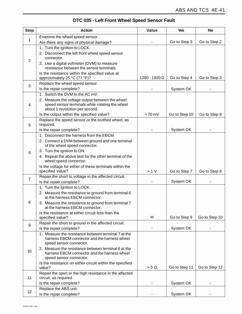
DTC 035 - Left Front Wheel Speed Sensor Fault
1
Action Yes NoValue
2
3
Go to Step 3 Go to Step 2-
4
Go to Step 7 Go to Step 8> 1 V
5
Go to Step 9 Go to Step 10∞
6
7
8
9
System OK --
10
11
System OK --
12
Go to Step 11 Go to Step 12> 5 Ω
System OK --
System OK --
System OK --
Go to Step 4 Go to Step 31280 - 1920 Ω
Examine the wheel speed sensor.Are there any signs of physical damage?1. Turn the ignition to LOCK.2. Disconnect the left front wheel speed sensor
connector.3. Use a digital voltmeter (DVM) to measure
resistance between the sensor terminals.Is the resistance within the specified value atapproximately 25 °C (77 °F)?Replace the wheel speed sensor.Is the repair complete?1. Switch the DVM to the AC mV.2. Measure the voltage output between the wheel
speed sensor terminals while rotating the wheelabout 1 revolution per second.
Is the output within the specified value?Replace the speed sensor or the toothed wheel, asrequired.Is the repair complete?1. Disconnect the harness from the EBCM.2. Connect a DVM between ground and one terminal
of the wheel speed connector.3. Turn the ignition to ON.4. Repeat the above test for the other terminal of the
wheel speed connector.Is the voltage for either of these terminals within thespecified value?Repair the short to voltage in the affected circuit.Is the repair complete?1. Turn the ignition to LOCK.2. Measure the resistance to ground from terminal 6
at the harness EBCM connector.3. Measure the resistance to ground from terminal 7
at the harness EBCM connector.Is the resistance at either circuit less than thespecified value?Repair the short to ground in the affected circuit.Is the repair complete?1. Measure the resistance between terminal 7 at the
harness EBCM connector and the harness wheelspeed sensor connector.
2. Measure the resistance between terminal 6 at theharness EBCM connector and the harness wheelspeed sensor connector.
Is the resistance on either circuit within the specifiedvalue?Repair the open or the high resistance in the affectedcircuit, as required.Is the repair complete?Replace the ABS unit.Is the repair complete?
Go to Step 10 Go to Step 9≈ 70 mV
SSANGYONG Y200
4E-42 ABS AND TCS
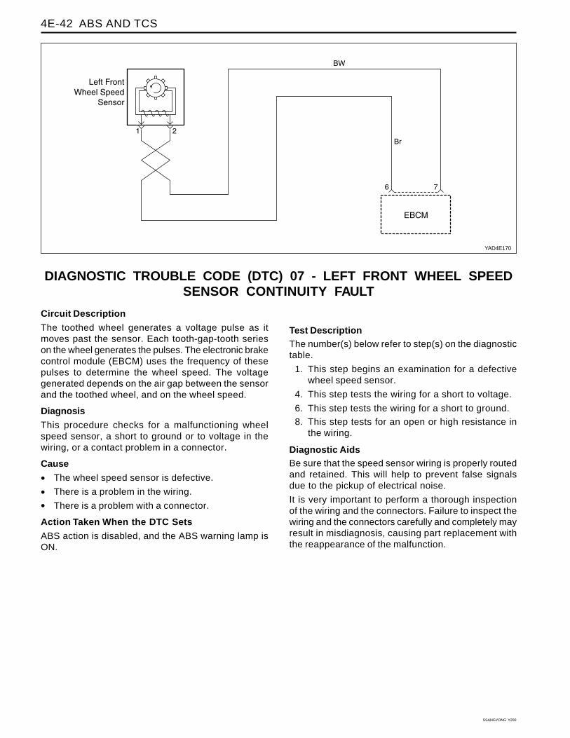
DIAGNOSTIC TROUBLE CODE (DTC) 07 - LEFT FRONT WHEEL SPEEDSENSOR CONTINUITY FAULT
YAD4E170
Circuit Description
The toothed wheel generates a voltage pulse as itmoves past the sensor. Each tooth-gap-tooth serieson the wheel generates the pulses. The electronic brakecontrol module (EBCM) uses the frequency of thesepulses to determine the wheel speed. The voltagegenerated depends on the air gap between the sensorand the toothed wheel, and on the wheel speed.
Diagnosis
This procedure checks for a malfunctioning wheelspeed sensor, a short to ground or to voltage in thewiring, or a contact problem in a connector.
Cause
• The wheel speed sensor is defective.
• There is a problem in the wiring.
• There is a problem with a connector.
Action Taken When the DTC Sets
ABS action is disabled, and the ABS warning lamp isON.
Test DescriptionThe number(s) below refer to step(s) on the diagnostictable.
1. This step begins an examination for a defectivewheel speed sensor.
4. This step tests the wiring for a short to voltage.
6. This step tests the wiring for a short to ground.
8. This step tests for an open or high resistance inthe wiring.
Diagnostic AidsBe sure that the speed sensor wiring is properly routedand retained. This will help to prevent false signalsdue to the pickup of electrical noise.
It is very important to perform a thorough inspectionof the wiring and the connectors. Failure to inspect thewiring and the connectors carefully and completely mayresult in misdiagnosis, causing part replacement withthe reappearance of the malfunction.
ABS AND TCS 4E-43
SSANGYONG Y200
Step
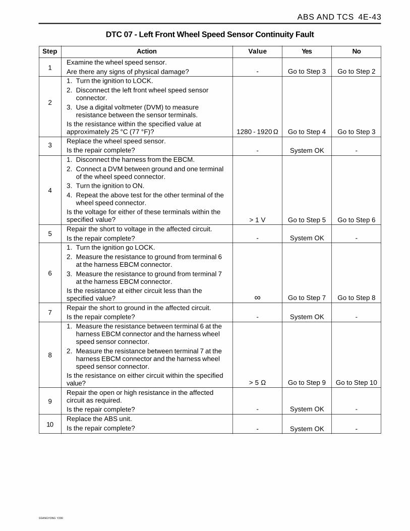
Examine the wheel speed sensor.Are there any signs of physical damage?1. Turn the ignition to LOCK.2. Disconnect the left front wheel speed sensor
connector.3. Use a digital voltmeter (DVM) to measure
resistance between the sensor terminals.Is the resistance within the specified value atapproximately 25 °C (77 °F)?Replace the wheel speed sensor.Is the repair complete?1. Disconnect the harness from the EBCM.2. Connect a DVM between ground and one terminal
of the wheel speed connector.3. Turn the ignition to ON.4. Repeat the above test for the other terminal of the
wheel speed connector.Is the voltage for either of these terminals within thespecified value?Repair the short to voltage in the affected circuit.Is the repair complete?1. Turn the ignition go LOCK.2. Measure the resistance to ground from terminal 6
at the harness EBCM connector.3. Measure the resistance to ground from terminal 7
at the harness EBCM connector.Is the resistance at either circuit less than thespecified value?Repair the short to ground in the affected circuit.Is the repair complete?1. Measure the resistance between terminal 6 at the
harness EBCM connector and the harness wheelspeed sensor connector.
2. Measure the resistance between terminal 7 at theharness EBCM connector and the harness wheelspeed sensor connector.
Is the resistance on either circuit within the specifiedvalue?Repair the open or high resistance in the affectedcircuit as required.Is the repair complete?Replace the ABS unit.Is the repair complete?
DTC 07 - Left Front Wheel Speed Sensor Continuity Fault
1
Action Yes NoValue
2
3
Go to Step 3 Go to Step 2-
4
Go to Step 7 Go to Step 8∞
5
Go to Step 9 Go to Step 10> 5 Ω
6
7
8
Go to Step 5 Go to Step 6> 1 V
9
System OK --
10
System OK --
System OK --
System OK --
System OK --
Go to Step 4 Go to Step 31280 - 1920 Ω
SSANGYONG Y200
4E-44 ABS AND TCS
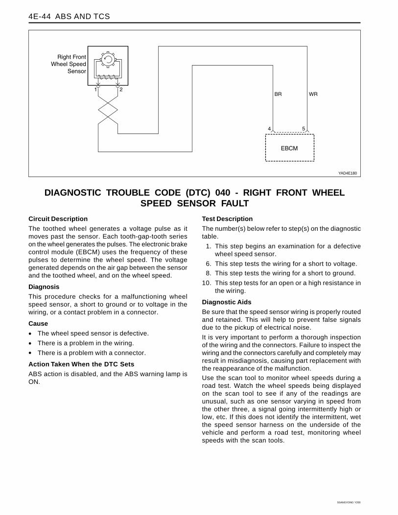
DIAGNOSTIC TROUBLE CODE (DTC) 040 - RIGHT FRONT WHEELSPEED SENSOR FAULT
YAD4E180
Circuit Description
The toothed wheel generates a voltage pulse as itmoves past the sensor. Each tooth-gap-tooth serieson the wheel generates the pulses. The electronic brakecontrol module (EBCM) uses the frequency of thesepulses to determine the wheel speed. The voltagegenerated depends on the air gap between the sensorand the toothed wheel, and on the wheel speed.
Diagnosis
This procedure checks for a malfunctioning wheelspeed sensor, a short to ground or to voltage in thewiring, or a contact problem in a connector.
Cause
• The wheel speed sensor is defective.
• There is a problem in the wiring.
• There is a problem with a connector.
Action Taken When the DTC Sets
ABS action is disabled, and the ABS warning lamp isON.
Test Description
The number(s) below refer to step(s) on the diagnostictable.
1. This step begins an examination for a defectivewheel speed sensor.
6. This step tests the wiring for a short to voltage.
8. This step tests the wiring for a short to ground.
10. This step tests for an open or a high resistance inthe wiring.
Diagnostic Aids
Be sure that the speed sensor wiring is properly routedand retained. This will help to prevent false signalsdue to the pickup of electrical noise.
It is very important to perform a thorough inspectionof the wiring and the connectors. Failure to inspect thewiring and the connectors carefully and completely mayresult in misdiagnosis, causing part replacement withthe reappearance of the malfunction.
Use the scan tool to monitor wheel speeds during aroad test. Watch the wheel speeds being displayedon the scan tool to see if any of the readings areunusual, such as one sensor varying in speed fromthe other three, a signal going intermittently high orlow, etc. If this does not identify the intermittent, wetthe speed sensor harness on the underside of thevehicle and perform a road test, monitoring wheelspeeds with the scan tools.
ABS AND TCS 4E-45
SSANGYONG Y200
System OK --
Step
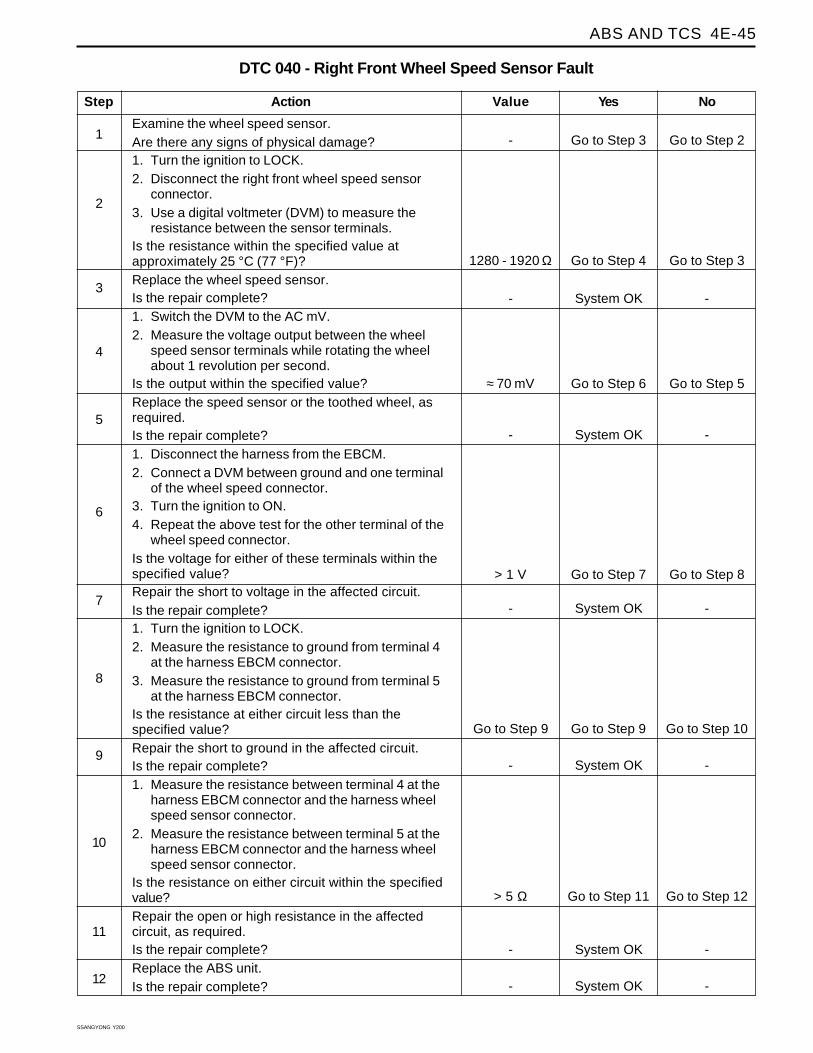
Examine the wheel speed sensor.Are there any signs of physical damage?1. Turn the ignition to LOCK.2. Disconnect the right front wheel speed sensor
connector.3. Use a digital voltmeter (DVM) to measure the
resistance between the sensor terminals.Is the resistance within the specified value atapproximately 25 °C (77 °F)?Replace the wheel speed sensor.Is the repair complete?1. Switch the DVM to the AC mV.2. Measure the voltage output between the wheel
speed sensor terminals while rotating the wheelabout 1 revolution per second.
Is the output within the specified value?Replace the speed sensor or the toothed wheel, asrequired.Is the repair complete?1. Disconnect the harness from the EBCM.2. Connect a DVM between ground and one terminal
of the wheel speed connector.3. Turn the ignition to ON.4. Repeat the above test for the other terminal of the
wheel speed connector.Is the voltage for either of these terminals within thespecified value?Repair the short to voltage in the affected circuit.Is the repair complete?1. Turn the ignition to LOCK.2. Measure the resistance to ground from terminal 4
at the harness EBCM connector.3. Measure the resistance to ground from terminal 5
at the harness EBCM connector.Is the resistance at either circuit less than thespecified value?Repair the short to ground in the affected circuit.Is the repair complete?1. Measure the resistance between terminal 4 at the
harness EBCM connector and the harness wheelspeed sensor connector.
2. Measure the resistance between terminal 5 at theharness EBCM connector and the harness wheelspeed sensor connector.
Is the resistance on either circuit within the specifiedvalue?Repair the open or high resistance in the affectedcircuit, as required.Is the repair complete?Replace the ABS unit.Is the repair complete?
DTC 040 - Right Front Wheel Speed Sensor Fault
1
Action Yes NoValue
2
3
Go to Step 3 Go to Step 2-
4
Go to Step 7 Go to Step 8> 1 V
5
Go to Step 9 Go to Step 10Go to Step 9
6
7
8
Go to Step 6 Go to Step 5≈ 70 mV
9
System OK --
10
11
System OK --
12
Go to Step 11 Go to Step 12> 5 Ω
System OK --
System OK --
System OK --
Go to Step 4 Go to Step 31280 - 1920 Ω
SSANGYONG Y200
4E-46 ABS AND TCS
DIAGNOSTIC TROUBLE CODE (DTC) 08 - RIGHT FRONT WHEEL SPEEDSENSOR CONTINUITY FAULT
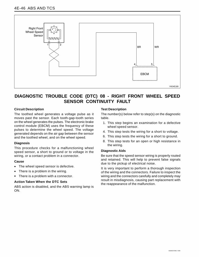
YAD4E180
Circuit Description
The toothed wheel generates a voltage pulse as itmoves past the sensor. Each tooth-gap-tooth serieson the wheel generates the pulses. The electronic brakecontrol module (EBCM) uses the frequency of thesepulses to determine the wheel speed. The voltagegenerated depends on the air gap between the sensorand the toothed wheel, and on the wheel speed.
Diagnosis
This procedure checks for a malfunctioning wheelspeed sensor, a short to ground or to voltage in thewiring, or a contact problem in a connector.
Cause
• The wheel speed sensor is defective.
• There is a problem in the wiring.
• There is a problem with a connector.
Action Taken When the DTC Sets
ABS action is disabled, and the ABS warning lamp isON.
Test Description
The number(s) below refer to step(s) on the diagnostictable.
1. This step begins an examination for a defectivewheel speed sensor.
4. This step tests the wiring for a short to voltage.
6. This step tests the wiring for a short to ground.
8. This step tests for an open or high resistance inthe wiring.
Diagnostic Aids
Be sure that the speed sensor wiring is properly routedand retained. This will help to prevent false signalsdue to the pickup of electrical noise.
It is very important to perform a thorough inspectionof the wiring and the connectors. Failure to inspect thewiring and the connectors carefully and completely mayresult in misdiagnosis, causing part replacement withthe reappearance of the malfunction.
ABS AND TCS 4E-47
SSANGYONG Y200
Step
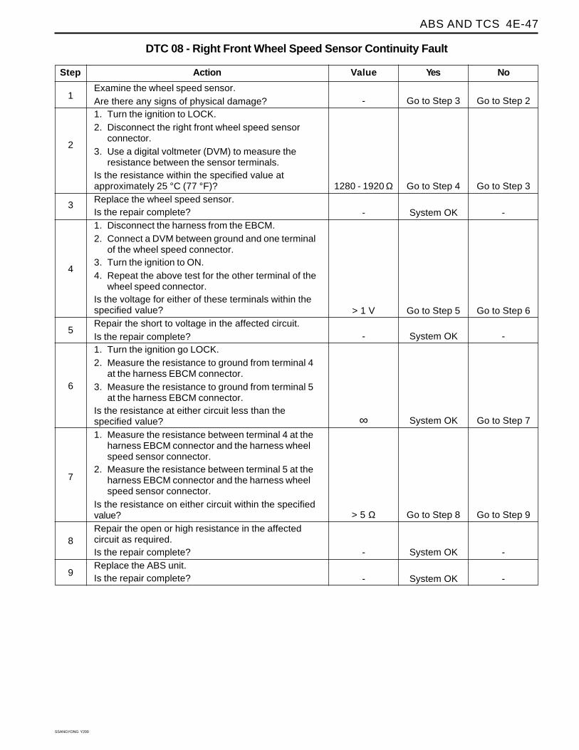
Examine the wheel speed sensor.Are there any signs of physical damage?1. Turn the ignition to LOCK.2. Disconnect the right front wheel speed sensor
connector.3. Use a digital voltmeter (DVM) to measure the
resistance between the sensor terminals.Is the resistance within the specified value atapproximately 25 °C (77 °F)?Replace the wheel speed sensor.Is the repair complete?1. Disconnect the harness from the EBCM.2. Connect a DVM between ground and one terminal
of the wheel speed connector.3. Turn the ignition to ON.4. Repeat the above test for the other terminal of the
wheel speed connector.Is the voltage for either of these terminals within thespecified value?Repair the short to voltage in the affected circuit.Is the repair complete?1. Turn the ignition go LOCK.2. Measure the resistance to ground from terminal 4
at the harness EBCM connector.3. Measure the resistance to ground from terminal 5
at the harness EBCM connector.Is the resistance at either circuit less than thespecified value?1. Measure the resistance between terminal 4 at the
harness EBCM connector and the harness wheelspeed sensor connector.
2. Measure the resistance between terminal 5 at theharness EBCM connector and the harness wheelspeed sensor connector.
Is the resistance on either circuit within the specifiedvalue?Repair the open or high resistance in the affectedcircuit as required.Is the repair complete?Replace the ABS unit.Is the repair complete?
DTC 08 - Right Front Wheel Speed Sensor Continuity Fault
1
Action Yes NoValue
2
3
Go to Step 3 Go to Step 2-
4
System OK Go to Step 7∞
5
Go to Step 8 Go to Step 9> 5 Ω
6
7
8
Go to Step 5 Go to Step 6> 1 V
9
System OK --
System OK --
System OK --
System OK --
Go to Step 4 Go to Step 31280 - 1920 Ω

SSANGYONG Y200
4E-48 ABS AND TCS
DIAGNOSTIC TROUBLE CODE (DTC) 045 - LEFT REAR WHEEL SPEEDSENSOR FAULT
YAD4E190
Circuit Description
The toothed wheel generates a voltage pulse as itmoves past the sensor. Each tooth-gap-tooth serieson the wheel generates the pulses. The electronic brakecontrol module (EBCM) uses the frequency of thesepulses to determine the wheel speed. The voltagegenerated depends on the air gap between the sensorand the toothed wheel, and on the wheel speed.
Diagnosis
This procedure checks for a malfunctioning wheelspeed sensor, a short to ground or to voltage in thewiring, or a contact problem in a connector.
Cause
• The wheel speed sensor is defect ive ordisconnected.
• There is a problem in the wiring.
• There is a problem with a connector.
Action Taken When the DTC Sets
ABS action is disabled, and the ABS warning lamp isON.
Test Description
The number(s) below refer to step(s) on the diagnostictable.
1. This step begins an examination for a defectivewheel speed sensor.
4. This step tests the wiring for a short to voltage.
6. This step tests the wiring for a short to ground.
8. This step tests for an open or a high resistance inthe wiring.
Diagnostic Aids
Be sure that the speed sensor wiring is properly routedand retained. This will help to prevent false signalsdue to the pickup of electrical noise.
It is very important to perform a thorough inspectionof the wiring and the connectors. Failure to inspect thewiring and the connectors carefully and completely mayresult in misdiagnosis, causing part replacement withthe reappearance of the malfunction.
Use the scan tool to monitor wheel speeds during aroad test. Watch the wheel speeds being displayedon the scan tool to see if any of the readings areunusual, such as one sensor varying in speed fromthe other three, a signal going intermittently high orlow, etc. If this does not identify the intermittent, wetthe speed sensor harness on the underside of thevehicle and perform a road test, monitoring the wheelspeeds with the scan tool.
ABS AND TCS 4E-49
SSANGYONG Y200
System OK --
Step
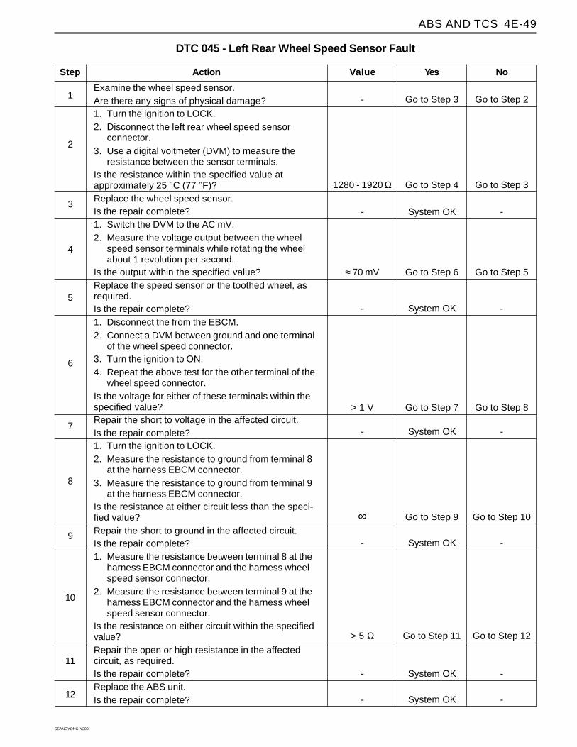
Examine the wheel speed sensor.Are there any signs of physical damage?1. Turn the ignition to LOCK.2. Disconnect the left rear wheel speed sensor
connector.3. Use a digital voltmeter (DVM) to measure the
resistance between the sensor terminals.Is the resistance within the specified value atapproximately 25 °C (77 °F)?Replace the wheel speed sensor.Is the repair complete?1. Switch the DVM to the AC mV.2. Measure the voltage output between the wheel
speed sensor terminals while rotating the wheelabout 1 revolution per second.
Is the output within the specified value?Replace the speed sensor or the toothed wheel, asrequired.Is the repair complete?1. Disconnect the from the EBCM.2. Connect a DVM between ground and one terminal
of the wheel speed connector.3. Turn the ignition to ON.4. Repeat the above test for the other terminal of the
wheel speed connector.Is the voltage for either of these terminals within thespecified value?Repair the short to voltage in the affected circuit.Is the repair complete?1. Turn the ignition to LOCK.2. Measure the resistance to ground from terminal 8
at the harness EBCM connector.3. Measure the resistance to ground from terminal 9
at the harness EBCM connector.Is the resistance at either circuit less than the speci-fied value?Repair the short to ground in the affected circuit.Is the repair complete?1. Measure the resistance between terminal 8 at the
harness EBCM connector and the harness wheelspeed sensor connector.
2. Measure the resistance between terminal 9 at theharness EBCM connector and the harness wheelspeed sensor connector.
Is the resistance on either circuit within the specifiedvalue?Repair the open or high resistance in the affectedcircuit, as required.Is the repair complete?Replace the ABS unit.Is the repair complete?
DTC 045 - Left Rear Wheel Speed Sensor Fault
1
Action Yes NoValue
2
3
Go to Step 3 Go to Step 2-
4
Go to Step 7 Go to Step 8> 1 V
5
Go to Step 9 Go to Step 10∞
6
7
8
Go to Step 6 Go to Step 5≈ 70 mV
9
System OK --
10
11
System OK --
12
Go to Step 11 Go to Step 12> 5 Ω
System OK --
System OK --
System OK --
Go to Step 4 Go to Step 31280 - 1920 Ω
SSANGYONG Y200
4E-50 ABS AND TCS
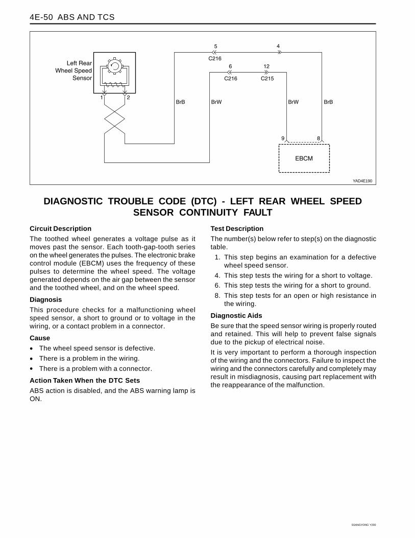
DIAGNOSTIC TROUBLE CODE (DTC) - LEFT REAR WHEEL SPEEDSENSOR CONTINUITY FAULT
YAD4E190
Circuit Description
The toothed wheel generates a voltage pulse as itmoves past the sensor. Each tooth-gap-tooth serieson the wheel generates the pulses. The electronic brakecontrol module (EBCM) uses the frequency of thesepulses to determine the wheel speed. The voltagegenerated depends on the air gap between the sensorand the toothed wheel, and on the wheel speed.
Diagnosis
This procedure checks for a malfunctioning wheelspeed sensor, a short to ground or to voltage in thewiring, or a contact problem in a connector.
Cause
• The wheel speed sensor is defective.
• There is a problem in the wiring.
• There is a problem with a connector.
Action Taken When the DTC Sets
ABS action is disabled, and the ABS warning lamp isON.
Test Description
The number(s) below refer to step(s) on the diagnostictable.
1. This step begins an examination for a defectivewheel speed sensor.
4. This step tests the wiring for a short to voltage.
6. This step tests the wiring for a short to ground.
8. This step tests for an open or high resistance inthe wiring.
Diagnostic Aids
Be sure that the speed sensor wiring is properly routedand retained. This will help to prevent false signalsdue to the pickup of electrical noise.
It is very important to perform a thorough inspectionof the wiring and the connectors. Failure to inspect thewiring and the connectors carefully and completely mayresult in misdiagnosis, causing part replacement withthe reappearance of the malfunction.
ABS AND TCS 4E-51
SSANGYONG Y200
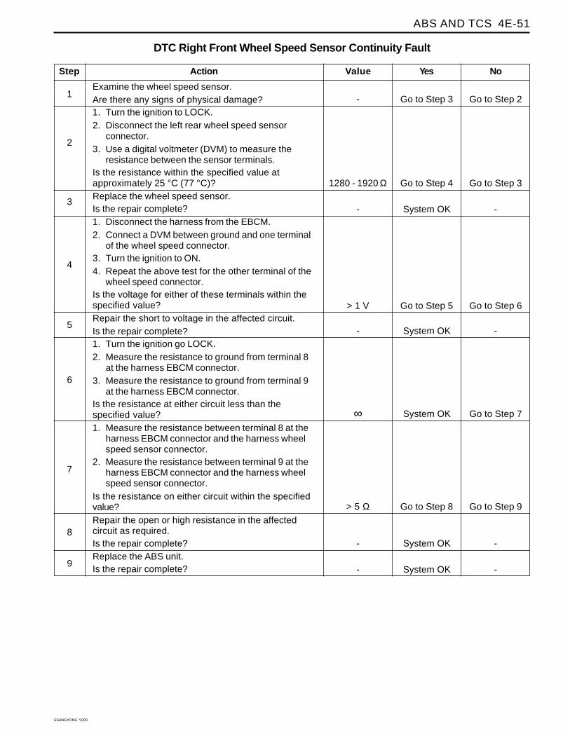
Step
Examine the wheel speed sensor.Are there any signs of physical damage?1. Turn the ignition to LOCK.2. Disconnect the left rear wheel speed sensor
connector.3. Use a digital voltmeter (DVM) to measure the
resistance between the sensor terminals.Is the resistance within the specified value atapproximately 25 °C (77 °C)?Replace the wheel speed sensor.Is the repair complete?1. Disconnect the harness from the EBCM.2. Connect a DVM between ground and one terminal
of the wheel speed connector.3. Turn the ignition to ON.4. Repeat the above test for the other terminal of the
wheel speed connector.Is the voltage for either of these terminals within thespecified value?Repair the short to voltage in the affected circuit.Is the repair complete?1. Turn the ignition go LOCK.2. Measure the resistance to ground from terminal 8
at the harness EBCM connector.3. Measure the resistance to ground from terminal 9
at the harness EBCM connector.Is the resistance at either circuit less than thespecified value?1. Measure the resistance between terminal 8 at the
harness EBCM connector and the harness wheelspeed sensor connector.
2. Measure the resistance between terminal 9 at theharness EBCM connector and the harness wheelspeed sensor connector.
Is the resistance on either circuit within the specifiedvalue?Repair the open or high resistance in the affectedcircuit as required.Is the repair complete?Replace the ABS unit.Is the repair complete?
DTC Right Front Wheel Speed Sensor Continuity Fault
1
Action Yes NoValue
2
3
Go to Step 3 Go to Step 2-
4
System OK Go to Step 7∞
5
Go to Step 8 Go to Step 9> 5 Ω
6
7
8
Go to Step 5 Go to Step 6> 1 V
9
System OK --
System OK --
System OK --
System OK --
Go to Step 4 Go to Step 31280 - 1920 Ω

SSANGYONG Y200
4E-52 ABS AND TCS
DIAGNOSTIC TROUBLE CODE (DTC) 050 - RIGHT REAR WHEEL SPEEDSENSOR FAULT
YAD4E200
Circuit Description
The toothed wheel generates a voltage pulse as itmoves past the sensor. Each tooth-gap-tooth serieson the wheel generates the pulses. The electronic brakecontrol module (EBCM) uses the frequency of thesepulses to determine the wheel speed. The voltagegenerated depends on the air gap between the sensorand the toothed wheel, and on the wheel speed.
Diagnosis
This procedure checks for a malfunctioning wheelspeed sensor, a short to ground or to voltage in thewiring, or a contact problem in a connector.
Cause
• The wheel speed sensor is defect ive ordisconnected.
• There is a problem in the wiring.
• There is a problem with a connector.
Action Taken When the DTC Sets
ABS action is disabled, and the ABS warning lamp isON.
Test Description
The number(s) below refer to step(s) on the diagnostictable.
1. This step begins an examination for a defectivewheel speed sensor.
6. This step tests the wiring for a short to voltage.
8. This step tests the wiring for a short to ground.
10. This step tests for an open or a high resistance inthe wiring.
Diagnostic Aids
Be sure that the speed sensor wiring is properly routedand retained. This will help to prevent false signalsdue to the pickup of electrical noise.
It is very important to perform a thorough inspectionof the wiring and the connectors. Failure to inspect thewiring and the connectors carefully and completely mayresult in misdiagnosis, causing part replacement withthe reappearance of the malfunction.
You can use the scan tool to monitor wheel speedsduring a road test. Watch the wheel speeds beingdisplayed on the scan tool to see if any of the readingsare unusual, such as one sensor varying in speed fromthe other three, a signal going intermittently high orlow, etc. If this does not identify the intermittent, wetthe speed sensor harness on the underside of thevehicle and perform a road test, monitoring the wheelspeeds with the scan tool.
ABS AND TCS 4E-53
SSANGYONG Y200
System OK --
Step
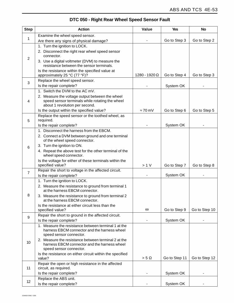
Examine the wheel speed sensor.Are there any signs of physical damage?1. Turn the ignition to LOCK.2. Disconnect the right rear wheel speed sensor
connector.3. Use a digital voltmeter (DVM) to measure the
resistance between the sensor terminals.Is the resistance within the specified value atapproximately 25 °C (77 °F)?Replace the wheel speed sensor.Is the repair complete?1. Switch the DVM to the AC mV.2. Measure the voltage output between the wheel
speed sensor terminals while rotating the wheelabout 1 revolution per second.
Is the output within the specified value?Replace the speed sensor or the toothed wheel, asrequired.Is the repair complete?1. Disconnect the harness from the EBCM.2. Connect a DVM between ground and one terminal
of the wheel speed connector.3. Turn the ignition to ON.4. Repeat the above test for the other terminal of the
wheel speed connector.Is the voltage for either of these terminals within thespecified value?Repair the short to voltage in the affected circuit.Is the repair complete?1. Turn the ignition to LOCK.2. Measure the resistance to ground from terminal 1
at the harness EBCM connector.3. Measure the resistance to ground from terminal 2
at the harness EBCM connector.Is the resistance at either circuit less than thespecified value?Repair the short to ground in the affected circuit.Is the repair complete?1. Measure the resistance between terminal 1 at the
harness EBCM connector and the harness wheelspeed sensor connector.
2. Measure the resistance between terminal 2 at theharness EBCM connector and the harness wheelspeed sensor connector.
Is the resistance on either circuit within the specifiedvalue?Repair the open or high resistance in the affectedcircuit, as required.Is the repair complete?Replace the ABS unit.Is the repair complete?
DTC 050 - Right Rear Wheel Speed Sensor Fault
1
Action Yes NoValue
2
3
Go to Step 3 Go to Step 2-
4
Go to Step 7 Go to Step 8> 1 V
5
Go to Step 9 Go to Step 10∞
6
7
8
Go to Step 6 Go to Step 5≈ 70 mV
9
System OK --
10
11
System OK --
12
Go to Step 11 Go to Step 12> 5 Ω
System OK --
System OK --
System OK --
Go to Step 4 Go to Step 31280 - 1920 Ω
SSANGYONG Y200
4E-54 ABS AND TCS
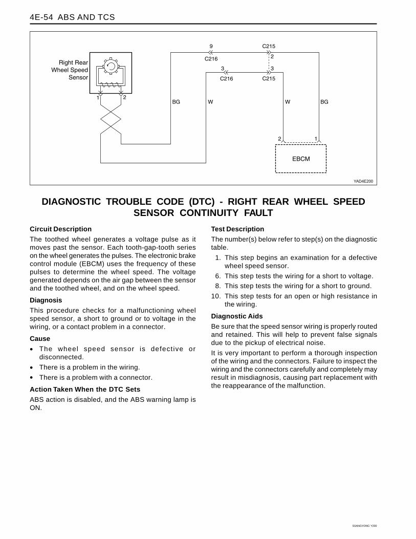
DIAGNOSTIC TROUBLE CODE (DTC) - RIGHT REAR WHEEL SPEEDSENSOR CONTINUITY FAULT
YAD4E200
Circuit Description
The toothed wheel generates a voltage pulse as itmoves past the sensor. Each tooth-gap-tooth serieson the wheel generates the pulses. The electronic brakecontrol module (EBCM) uses the frequency of thesepulses to determine the wheel speed. The voltagegenerated depends on the air gap between the sensorand the toothed wheel, and on the wheel speed.
Diagnosis
This procedure checks for a malfunctioning wheelspeed sensor, a short to ground or to voltage in thewiring, or a contact problem in a connector.
Cause
• The wheel speed sensor is defect ive ordisconnected.
• There is a problem in the wiring.
• There is a problem with a connector.
Action Taken When the DTC Sets
ABS action is disabled, and the ABS warning lamp isON.
Test Description
The number(s) below refer to step(s) on the diagnostictable.
1. This step begins an examination for a defectivewheel speed sensor.
6. This step tests the wiring for a short to voltage.
8. This step tests the wiring for a short to ground.
10. This step tests for an open or high resistance inthe wiring.
Diagnostic Aids
Be sure that the speed sensor wiring is properly routedand retained. This will help to prevent false signalsdue to the pickup of electrical noise.
It is very important to perform a thorough inspectionof the wiring and the connectors. Failure to inspect thewiring and the connectors carefully and completely mayresult in misdiagnosis, causing part replacement withthe reappearance of the malfunction.

ABS AND TCS 4E-55
SSANGYONG Y200
Step
Examine the wheel speed sensor.Are there any signs of physical damage?1. Turn the ignition to LOCK.2. Disconnect the right rear wheel speed sensor
connector.3. Use a digital voltmeter (DVM) to measure the
resistance between the sensor terminals.Is the resistance within the specified value atapproximately 25 °C (77 °C)?Replace the wheel speed sensor.Is the repair complete?1. Disconnect the harness from the EBCM.2. Connect a DVM between ground and one terminal
of the wheel speed connector.3. Turn the ignition to ON.4. Repeat the above test for the other terminal of the
wheel speed connector.Is the voltage for either of these terminals within thespecified value?Repair the short to voltage in the affected circuit.Is the repair complete?1. Turn the ignition go LOCK.2. Measure the resistance to ground from terminal 1
at the harness EBCM connector.3. Measure the resistance to ground from terminal 2
at the harness EBCM connector.Is the resistance at either circuit less than thespecified value?1. Measure the resistance between terminal 1 at the
harness EBCM connector and the harness wheelspeed sensor connector.
2. Measure the resistance between terminal 2 at theharness EBCM connector and the harness wheelspeed sensor connector.
Is the resistance on either circuit within the specifiedvalue?Repair the open or high resistance in the affectedcircuit as required.Is the repair complete?Replace the ABS unit.Is the repair complete?
Right Rear Wheel Speed Sensor Continuity Fault
1
Action Yes NoValue
2
3
Go to Step 3 Go to Step 2-
4
System OK Go to Step 7∞
5
Go to Step 8 Go to Step 9> 5 Ω
6
7
8
Go to Step 5 Go to Step 6> 1 V
9
System OK --
System OK --
System OK --
System OK --
Go to Step 4 Go to Step 31280 - 1920 Ω
SSANGYONG Y200
4E-56 ABS AND TCS
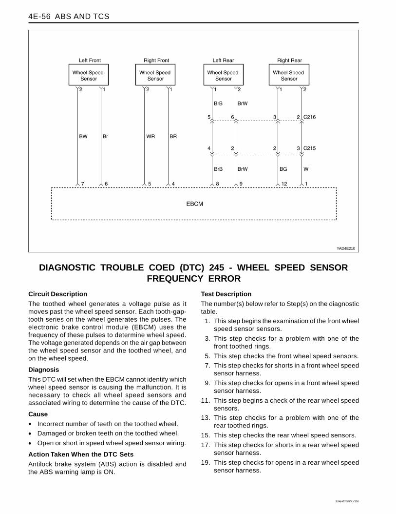
DIAGNOSTIC TROUBLE COED (DTC) 245 - WHEEL SPEED SENSORFREQUENCY ERROR
YAD4E210
Circuit Description
The toothed wheel generates a voltage pulse as itmoves past the wheel speed sensor. Each tooth-gap-tooth series on the wheel generates the pulses. Theelectronic brake control module (EBCM) uses thefrequency of these pulses to determine wheel speed.The voltage generated depends on the air gap betweenthe wheel speed sensor and the toothed wheel, andon the wheel speed.
Diagnosis
This DTC will set when the EBCM cannot identify whichwheel speed sensor is causing the malfunction. It isnecessary to check all wheel speed sensors andassociated wiring to determine the cause of the DTC.
Cause
• Incorrect number of teeth on the toothed wheel.
• Damaged or broken teeth on the toothed wheel.
• Open or short in speed wheel speed sensor wiring.
Action Taken When the DTC Sets
Antilock brake system (ABS) action is disabled andthe ABS warning lamp is ON.
Test Description
The number(s) below refer to Step(s) on the diagnostictable.
1. This step begins the examination of the front wheelspeed sensor sensors.
3. This step checks for a problem with one of thefront toothed rings.
5. This step checks the front wheel speed sensors.
7. This step checks for shorts in a front wheel speedsensor harness.
9. This step checks for opens in a front wheel speedsensor harness.
11. This step begins a check of the rear wheel speedsensors.
13. This step checks for a problem with one of therear toothed rings.
15. This step checks the rear wheel speed sensors.
17. This step checks for shorts in a rear wheel speedsensor harness.
19. This step checks for opens in a rear wheel speedsensor harness.
ABS AND TCS 4E-57
SSANGYONG Y200
Diagnostic AidsDTC 11 may be set by running the scan tool auto testif the throttle angle readings are not updating while inthe date list mode. If this is the case, clear the DTCs,disconnect the scan tool, and road test the vehicle toat least 25 km/h (15 mph) to see if the DTC resets.
Check the toothed wheels for any large grooves,gouges, marks, etc. that might influence the tooth’ssignal at the wheel speed sensor. Also, check for abuildup of foreign material in the gaps between the
teeth in the toothed wheel, as this material may causethis malfunction.
A badly worn hub/bearing assembly may cause thismalfunction. The wheel speed sensor-to-toothed wheelair gap may change excessively due to bearing play.
If an improper rear hub assembly or front outer constantvelocity joint is installed, one with a toothed wheelcontaining the incorrect number of teeth, this DTC canset. Be sure that all the toothed wheels have 52 teeth.
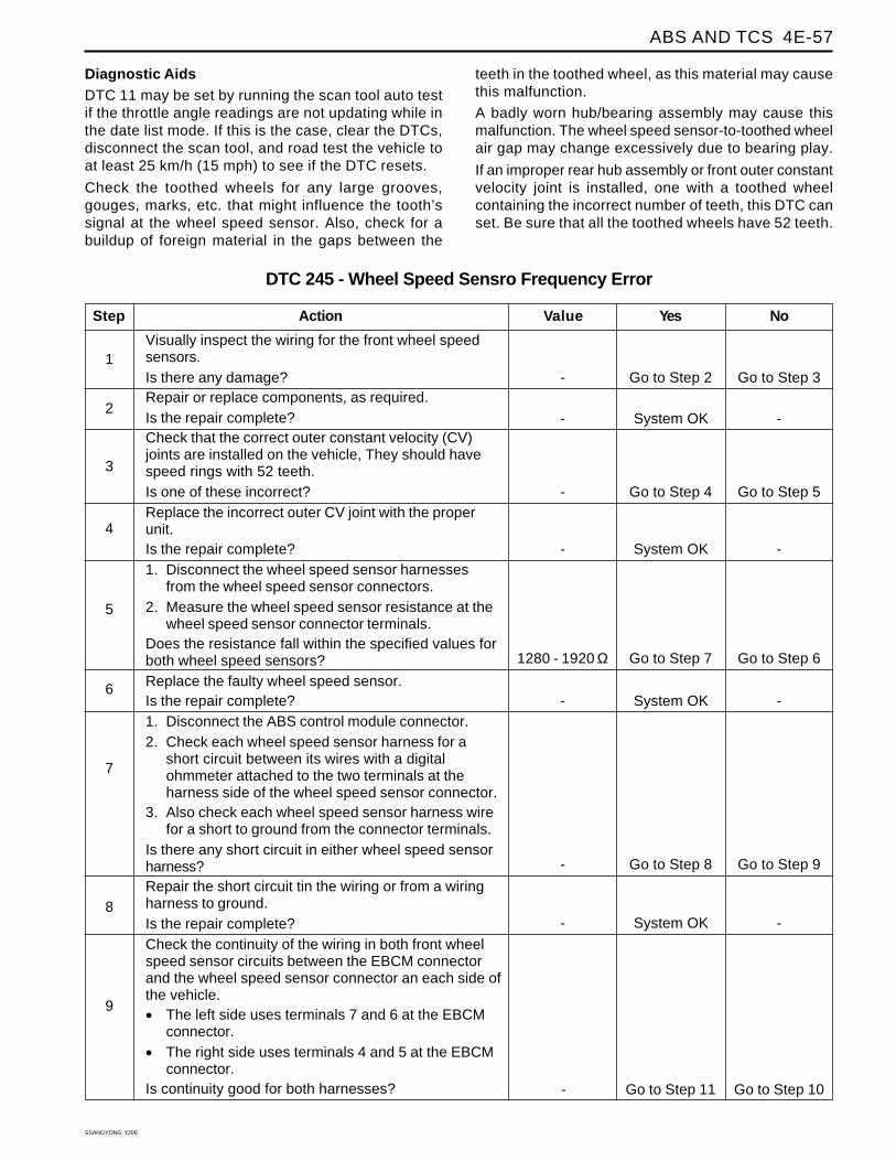
Step
Visually inspect the wiring for the front wheel speedsensors.Is there any damage?Repair or replace components, as required.Is the repair complete?Check that the correct outer constant velocity (CV)joints are installed on the vehicle, They should havespeed rings with 52 teeth.Is one of these incorrect?Replace the incorrect outer CV joint with the properunit.Is the repair complete?1. Disconnect the wheel speed sensor harnesses
from the wheel speed sensor connectors.2. Measure the wheel speed sensor resistance at the
wheel speed sensor connector terminals.Does the resistance fall within the specified values forboth wheel speed sensors?Replace the faulty wheel speed sensor.Is the repair complete?1. Disconnect the ABS control module connector.2. Check each wheel speed sensor harness for a
short circuit between its wires with a digitalohmmeter attached to the two terminals at theharness side of the wheel speed sensor connector.
3. Also check each wheel speed sensor harness wirefor a short to ground from the connector terminals.
Is there any short circuit in either wheel speed sensorharness?Repair the short circuit tin the wiring or from a wiringharness to ground.Is the repair complete?Check the continuity of the wiring in both front wheelspeed sensor circuits between the EBCM connectorand the wheel speed sensor connector an each side ofthe vehicle.
• The left side uses terminals 7 and 6 at the EBCMconnector.
• The right side uses terminals 4 and 5 at the EBCMconnector.
Is continuity good for both harnesses?
DTC 245 - Wheel Speed Sensro Frequency Error
1
Action Yes NoValue
2
3
Go to Step 2 Go to Step 3-
4
5
Go to Step 7 Go to Step 61280 - 1920 Ω
6
7
8
Go to Step 4 Go to Step 5-
9
System OK --
System OK --
System OK --
Go to Step 11 Go to Step 10-
Go to Step 8 Go to Step 9-
System OK --
SSANGYONG Y200
4E-58 ABS AND TCS
System OK Go to Step 19-
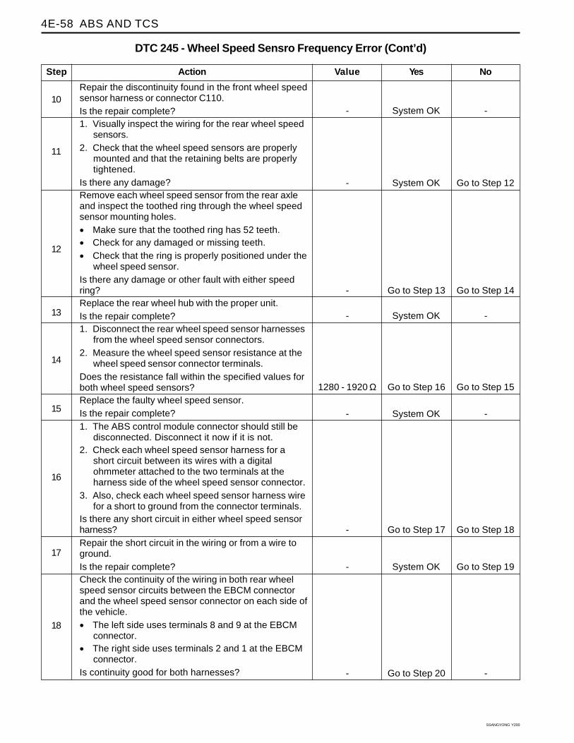
Step
Repair the discontinuity found in the front wheel speedsensor harness or connector C110.Is the repair complete?1. Visually inspect the wiring for the rear wheel speed
sensors.2. Check that the wheel speed sensors are properly
mounted and that the retaining belts are properlytightened.
Is there any damage?Remove each wheel speed sensor from the rear axleand inspect the toothed ring through the wheel speedsensor mounting holes.
• Make sure that the toothed ring has 52 teeth.
• Check for any damaged or missing teeth.
• Check that the ring is properly positioned under thewheel speed sensor.
Is there any damage or other fault with either speedring?Replace the rear wheel hub with the proper unit.Is the repair complete?1. Disconnect the rear wheel speed sensor harnesses
from the wheel speed sensor connectors.2. Measure the wheel speed sensor resistance at the
wheel speed sensor connector terminals.Does the resistance fall within the specified values forboth wheel speed sensors?Replace the faulty wheel speed sensor.Is the repair complete?1. The ABS control module connector should still be
disconnected. Disconnect it now if it is not.2. Check each wheel speed sensor harness for a
short circuit between its wires with a digitalohmmeter attached to the two terminals at theharness side of the wheel speed sensor connector.
3. Also, check each wheel speed sensor harness wirefor a short to ground from the connector terminals.
Is there any short circuit in either wheel speed sensorharness?Repair the short circuit in the wiring or from a wire toground.Is the repair complete?Check the continuity of the wiring in both rear wheelspeed sensor circuits between the EBCM connectorand the wheel speed sensor connector on each side ofthe vehicle.
• The left side uses terminals 8 and 9 at the EBCMconnector.
• The right side uses terminals 2 and 1 at the EBCMconnector.
Is continuity good for both harnesses?
DTC 245 - Wheel Speed Sensro Frequency Error (Cont’d)
10
Action Yes NoValue
11
12
System OK Go to Step 12-
14
15
Go to Step 16 Go to Step 151280 - 1920 Ω
16
17
18
Go to Step 13 Go to Step 14-
System OK --
System OK --
System OK --
Go to Step 17 Go to Step 18-
13
Go to Step 20 --
ABS AND TCS 4E-59
SSANGYONG Y200
System OK --
System OK --
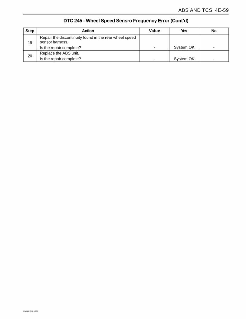
Step
Repair the discontinuity found in the rear wheel speedsensor harness.Is the repair complete?Replace the ABS unit.Is the repair complete?
DTC 245 - Wheel Speed Sensro Frequency Error (Cont’d)
Action Yes NoValue
19
20

SSANGYONG Y200
4E-60 ABS AND TCS
DIAGNOSTIC TROUBLE CODE (DTC) 930 - ACCELERATION SENSORFAULT
YAD4E220
Circuit Description
The acceleration sensor provides a voltage signal thatchanges in relation to the acceleration of vehicle. Thesignal voltage will vary from about 1.95 to 3.45 volt.The electronic brake control module (EBCM) monitor asignal voltage of deceleration in the vehicle.
Diagnosis
This procedure checks for a malfunct ioningacceleration sensor, a short to ground or to voltage inthe wiring or a contact problem in a connector.
Cause
• The vertical acceleration sensor is defective ordisconnected.
• There is a problem in the wiring.
• There is a problem with a connector
• Wrong installed vertical acceleration sensor
Fail ActionABS action is disabled, and the ABS warning lamp isON.
Test Description
The number(s) below refer to step(s) on the diagnostictable.
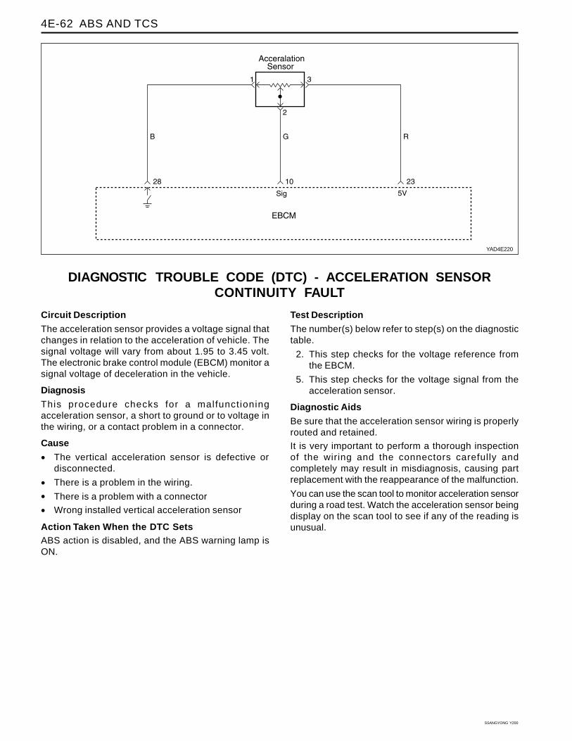
2. This step checks for the voltage reference fromthe EBCM.
5. This step checks for the voltage signal from theacceleration sensor.
Diagnostic Aids
Be sure that the acceleration sensor wiring is properlyrouted and retained.
It is very important to perform a thorough inspectionof the wiring and the connectors carefully andcompletely may result in misdiagnosis, causing partreplacement with the reappearance of the malfunction.
You can use the scan tool to monitor acceleration sensorduring a road test. Watch the acceleration sensor beingdisplay on the scan tool to see if any of the reading isunusual.
ABS AND TCS 4E-61
SSANGYONG Y200
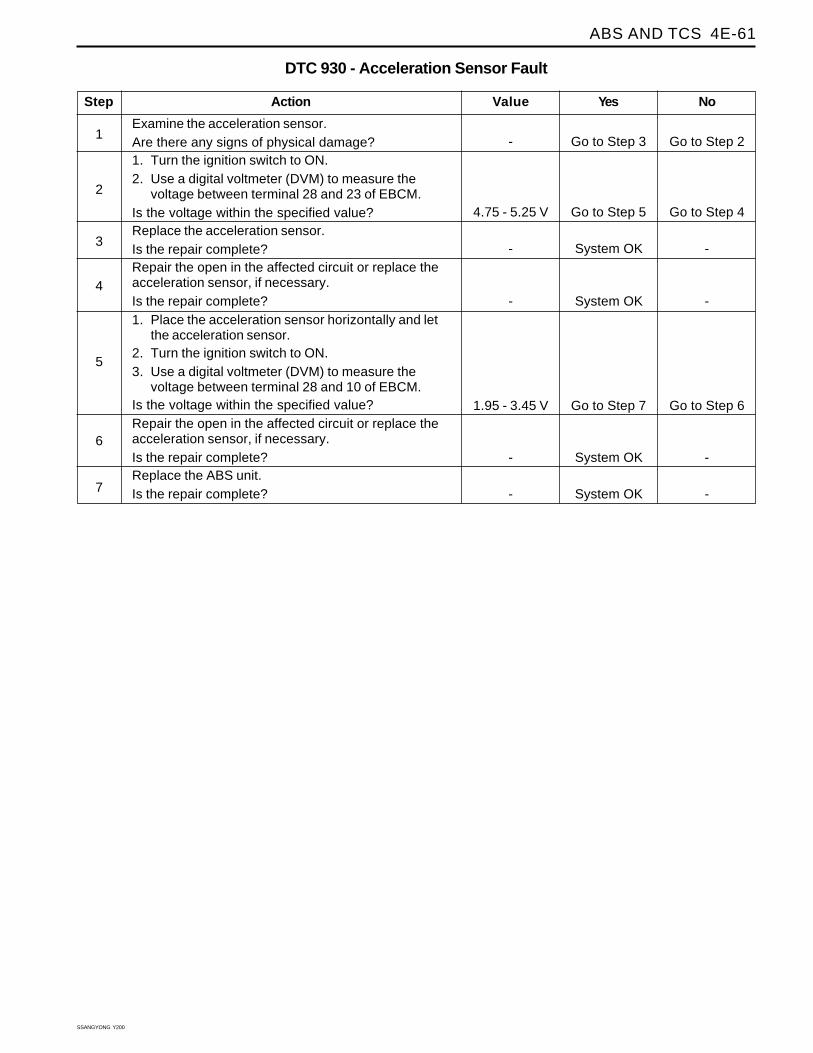
Step
Examine the acceleration sensor.Are there any signs of physical damage?1. Turn the ignition switch to ON.2. Use a digital voltmeter (DVM) to measure the
voltage between terminal 28 and 23 of EBCM.Is the voltage within the specified value?Replace the acceleration sensor.Is the repair complete?Repair the open in the affected circuit or replace theacceleration sensor, if necessary.Is the repair complete?1. Place the acceleration sensor horizontally and let
the acceleration sensor.2. Turn the ignition switch to ON.3. Use a digital voltmeter (DVM) to measure the
voltage between terminal 28 and 10 of EBCM.Is the voltage within the specified value?Repair the open in the affected circuit or replace theacceleration sensor, if necessary.Is the repair complete?Replace the ABS unit.Is the repair complete?
DTC 930 - Acceleration Sensor Fault
1
Action Yes NoValue
2
3
Go to Step 3 Go to Step 2-
4
5
6
7
Go to Step 7 Go to Step 61.95 - 3.45 V
System OK --
System OK --
System OK --
Go to Step 5 Go to Step 44.75 - 5.25 V
System OK --
SSANGYONG Y200
4E-62 ABS AND TCS
DIAGNOSTIC TROUBLE CODE (DTC) - ACCELERATION SENSORCONTINUITY FAULT
YAD4E220
Circuit Description
The acceleration sensor provides a voltage signal thatchanges in relation to the acceleration of vehicle. Thesignal voltage will vary from about 1.95 to 3.45 volt.The electronic brake control module (EBCM) monitor asignal voltage of deceleration in the vehicle.
Diagnosis
This procedure checks for a malfunct ioningacceleration sensor, a short to ground or to voltage inthe wiring, or a contact problem in a connector.
Cause
• The vertical acceleration sensor is defective ordisconnected.
• There is a problem in the wiring.
• There is a problem with a connector
• Wrong installed vertical acceleration sensor
Action Taken When the DTC SetsABS action is disabled, and the ABS warning lamp isON.
Test Description
The number(s) below refer to step(s) on the diagnostictable.
2. This step checks for the voltage reference fromthe EBCM.
5. This step checks for the voltage signal from theacceleration sensor.
Diagnostic Aids
Be sure that the acceleration sensor wiring is properlyrouted and retained.
It is very important to perform a thorough inspectionof the wiring and the connectors carefully andcompletely may result in misdiagnosis, causing partreplacement with the reappearance of the malfunction.
You can use the scan tool to monitor acceleration sensorduring a road test. Watch the acceleration sensor beingdisplay on the scan tool to see if any of the reading isunusual.
ABS AND TCS 4E-63
SSANGYONG Y200
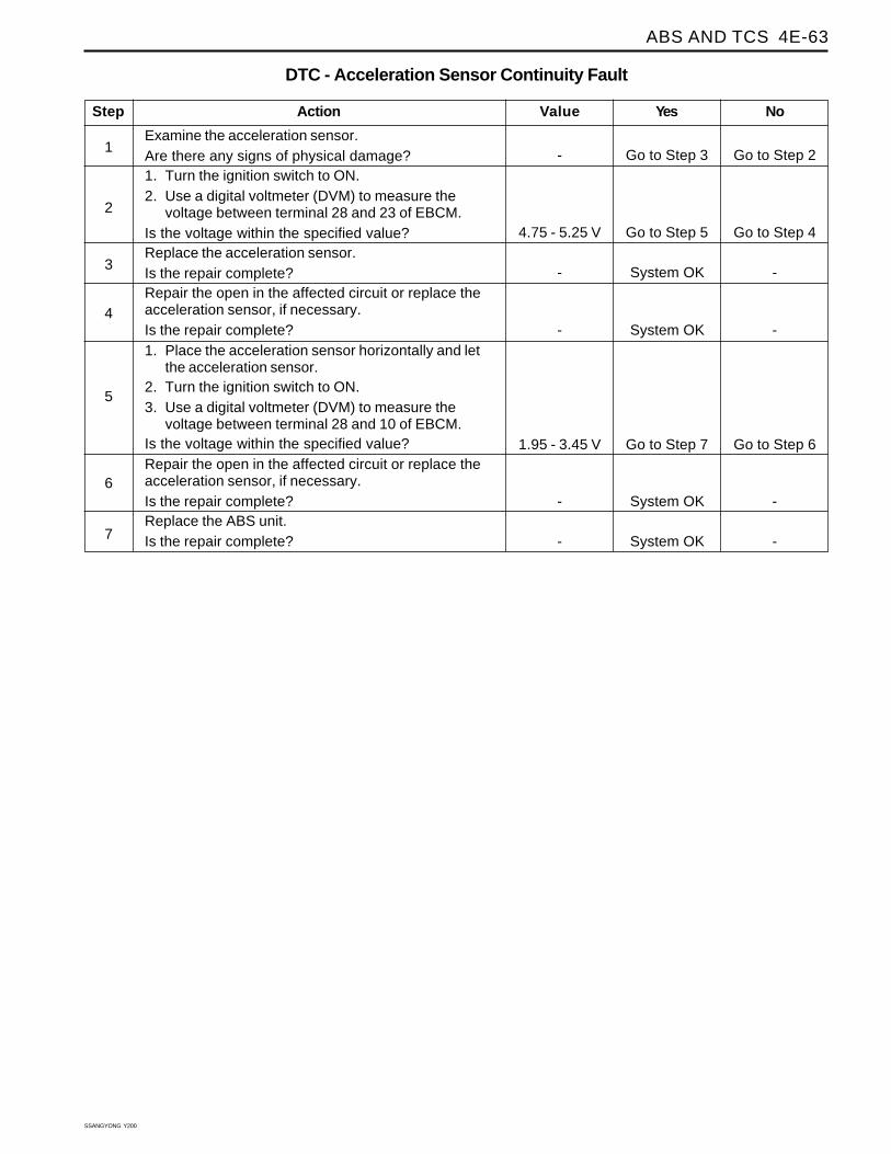
Step
Examine the acceleration sensor.Are there any signs of physical damage?1. Turn the ignition switch to ON.2. Use a digital voltmeter (DVM) to measure the
voltage between terminal 28 and 23 of EBCM.Is the voltage within the specified value?Replace the acceleration sensor.Is the repair complete?Repair the open in the affected circuit or replace theacceleration sensor, if necessary.Is the repair complete?1. Place the acceleration sensor horizontally and let
the acceleration sensor.2. Turn the ignition switch to ON.3. Use a digital voltmeter (DVM) to measure the
voltage between terminal 28 and 10 of EBCM.Is the voltage within the specified value?Repair the open in the affected circuit or replace theacceleration sensor, if necessary.Is the repair complete?Replace the ABS unit.Is the repair complete?
DTC - Acceleration Sensor Continuity Fault
1
Action Yes NoValue
2
3
Go to Step 3 Go to Step 2-
4
5
6
7
Go to Step 7 Go to Step 61.95 - 3.45 V
System OK --
System OK --
System OK --
Go to Step 5 Go to Step 44.75 - 5.25 V
System OK --
SSANGYONG Y200
4E-64 ABS AND TCS
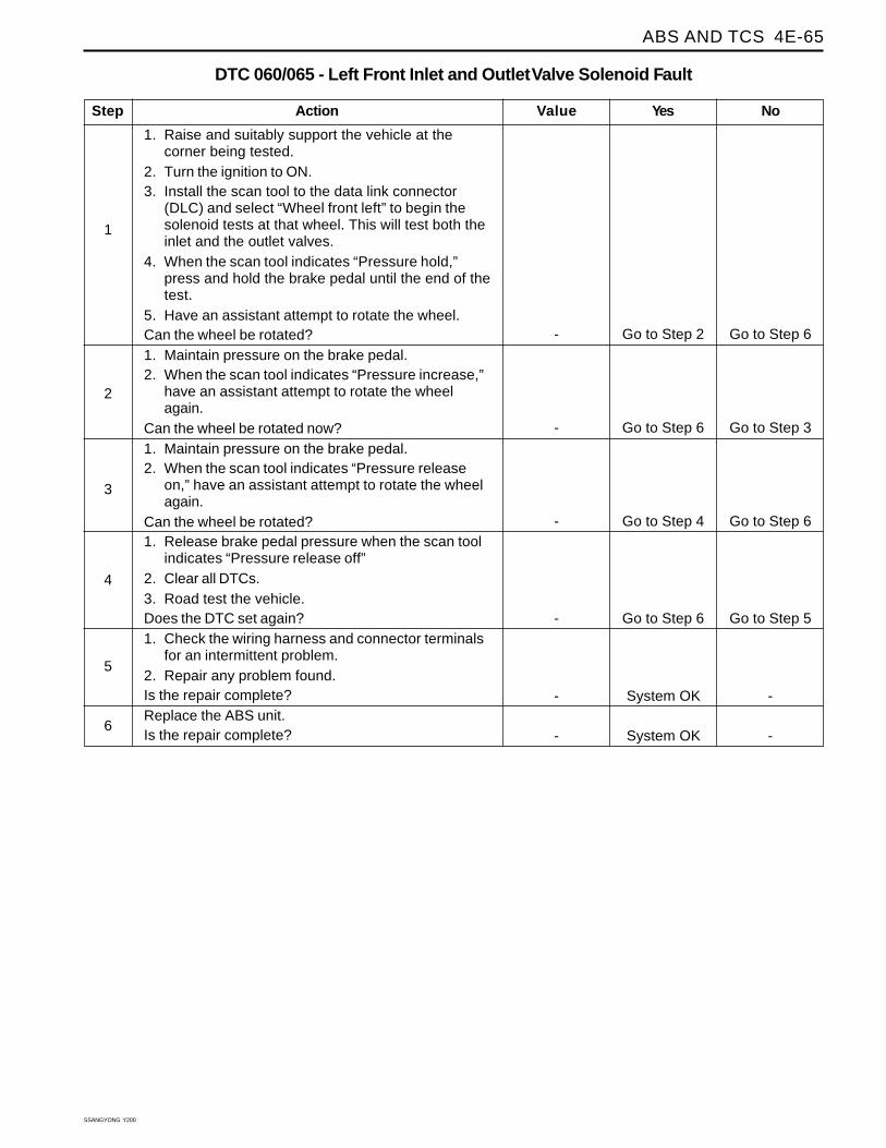
DIAGNOSTIC TROUBLE COED (DTC) 060/065 - LEFT FRONT INLET ANDOUTLET VALVE SOLENOID FAULT
YAD4E230
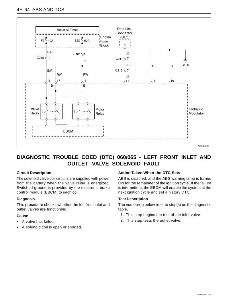
Circuit Description
The solenoid valve coil circuits are supplied with powerfrom the battery when the valve relay is energized.Switched ground is provided by the electronic brakecontrol module (EBCM) to each coil.
Diagnosis
This procedure checks whether the left front inlet andoutlet valves are functioning.
Cause
• A valve has failed.
• A solenoid coil is open or shorted.
Action Taken When the DTC Sets
ABS is disabled, and the ABS warning lamp is turnedON for the remainder of the ignition cycle. If the failureis intermittent, the EBCM will enable the system at thenext ignition cycle and set a history DTC.
Test Description
The number(s) below refer to step(s) on the diagnostictable.
1. This step begins the test of the inlet valve
3. This step tests the outlet valve.
ABS AND TCS 4E-65
SSANGYONG Y200
Step
1. Raise and suitably support the vehicle at thecorner being tested.
2. Turn the ignition to ON.3. Install the scan tool to the data link connector
(DLC) and select “Wheel front left” to begin thesolenoid tests at that wheel. This will test both theinlet and the outlet valves.
4. When the scan tool indicates “Pressure hold,”press and hold the brake pedal until the end of thetest.
5. Have an assistant attempt to rotate the wheel.Can the wheel be rotated?1. Maintain pressure on the brake pedal.2. When the scan tool indicates “Pressure increase,”
have an assistant attempt to rotate the wheelagain.
Can the wheel be rotated now?1. Maintain pressure on the brake pedal.2. When the scan tool indicates “Pressure release
on,” have an assistant attempt to rotate the wheelagain.
Can the wheel be rotated?1. Release brake pedal pressure when the scan tool
indicates “Pressure release off”2. Clear all DTCs.3. Road test the vehicle.Does the DTC set again?1. Check the wiring harness and connector terminals
for an intermittent problem.2. Repair any problem found.Is the repair complete?Replace the ABS unit.Is the repair complete?
DTC 060/065 - Left Front Inlet and Outlet Valve Solenoid Fault
1
Action Yes NoValue
2
3
Go to Step 2 Go to Step 6-
4
5
6
Go to Step 6 Go to Step 5-
System OK --
System OK --
Go to Step 6 Go to Step 3-
Go to Step 4 Go to Step 6-
SSANGYONG Y200
4E-66 ABS AND TCS
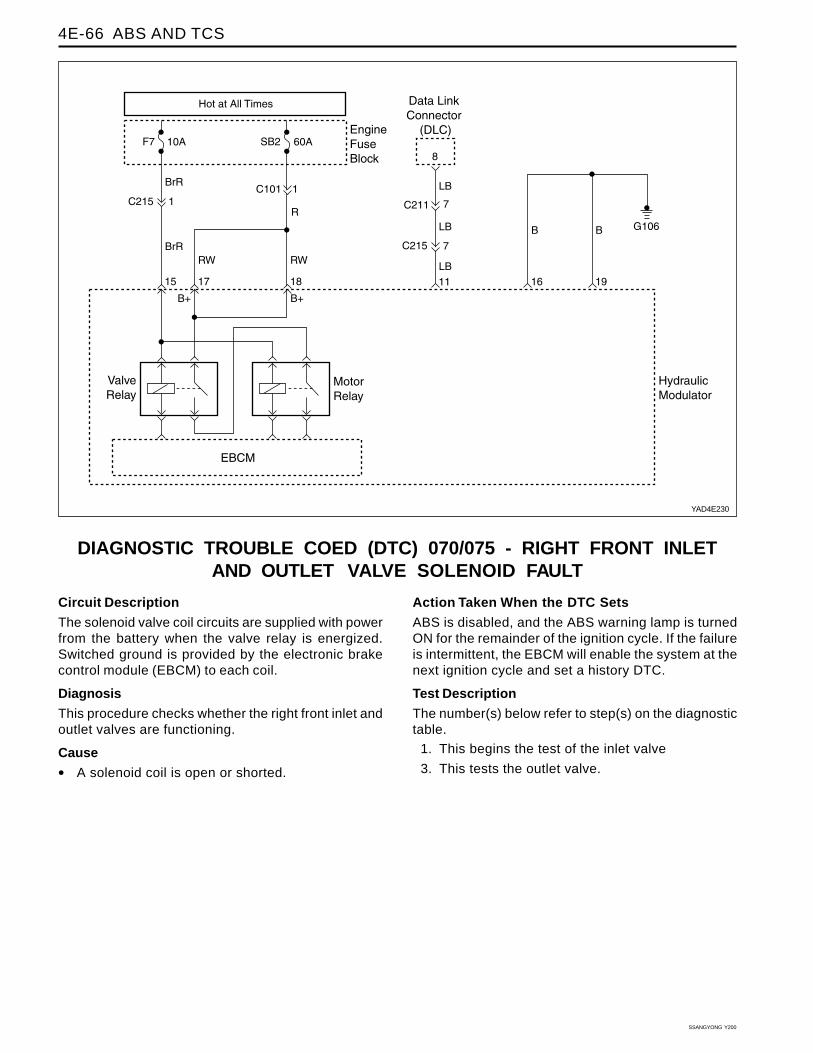
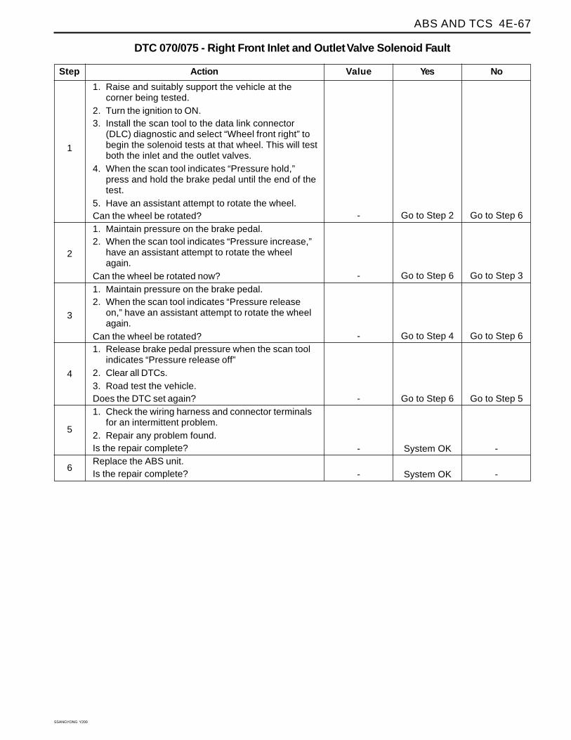
DIAGNOSTIC TROUBLE COED (DTC) 070/075 - RIGHT FRONT INLETAND OUTLET VALVE SOLENOID FAULT
YAD4E230
Circuit Description
The solenoid valve coil circuits are supplied with powerfrom the battery when the valve relay is energized.Switched ground is provided by the electronic brakecontrol module (EBCM) to each coil.
Diagnosis
This procedure checks whether the right front inlet andoutlet valves are functioning.
Cause
• A solenoid coil is open or shorted.
Action Taken When the DTC Sets
ABS is disabled, and the ABS warning lamp is turnedON for the remainder of the ignition cycle. If the failureis intermittent, the EBCM will enable the system at thenext ignition cycle and set a history DTC.
Test Description
The number(s) below refer to step(s) on the diagnostictable.
1. This begins the test of the inlet valve
3. This tests the outlet valve.
ABS AND TCS 4E-67
SSANGYONG Y200
Step
1. Raise and suitably support the vehicle at thecorner being tested.
2. Turn the ignition to ON.3. Install the scan tool to the data link connector
(DLC) diagnostic and select “Wheel front right” tobegin the solenoid tests at that wheel. This will testboth the inlet and the outlet valves.
4. When the scan tool indicates “Pressure hold,”press and hold the brake pedal until the end of thetest.
5. Have an assistant attempt to rotate the wheel.Can the wheel be rotated?1. Maintain pressure on the brake pedal.2. When the scan tool indicates “Pressure increase,”
have an assistant attempt to rotate the wheelagain.
Can the wheel be rotated now?1. Maintain pressure on the brake pedal.2. When the scan tool indicates “Pressure release
on,” have an assistant attempt to rotate the wheelagain.
Can the wheel be rotated?1. Release brake pedal pressure when the scan tool
indicates “Pressure release off”2. Clear all DTCs.3. Road test the vehicle.Does the DTC set again?1. Check the wiring harness and connector terminals
for an intermittent problem.2. Repair any problem found.Is the repair complete?Replace the ABS unit.Is the repair complete?
DTC 070/075 - Right Front Inlet and Outlet Valve Solenoid Fault
1
Action Yes NoValue
2
3
Go to Step 2 Go to Step 6-
4
5
6
Go to Step 6 Go to Step 5-
System OK --
System OK --
Go to Step 6 Go to Step 3-
Go to Step 4 Go to Step 6-
SSANGYONG Y200
4E-68 ABS AND TCS
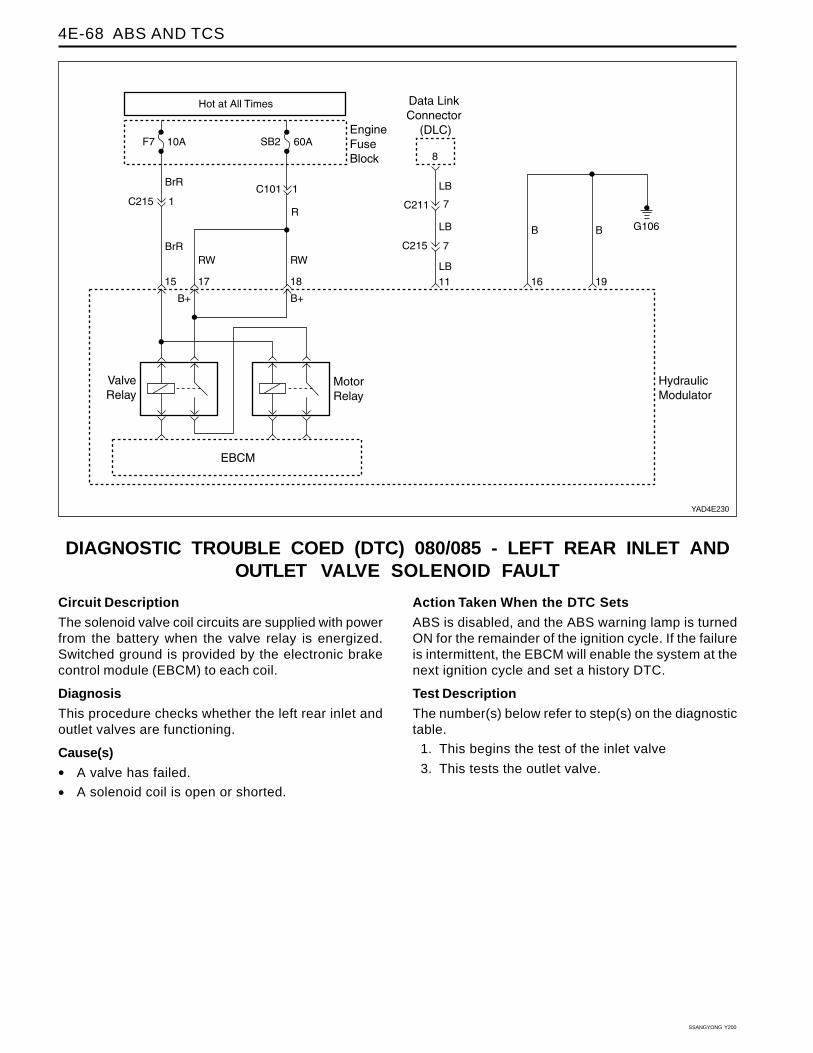
DIAGNOSTIC TROUBLE COED (DTC) 080/085 - LEFT REAR INLET ANDOUTLET VALVE SOLENOID FAULT
Circuit Description
The solenoid valve coil circuits are supplied with powerfrom the battery when the valve relay is energized.Switched ground is provided by the electronic brakecontrol module (EBCM) to each coil.
Diagnosis
This procedure checks whether the left rear inlet andoutlet valves are functioning.
Cause(s)
• A valve has failed.
• A solenoid coil is open or shorted.
Action Taken When the DTC Sets
ABS is disabled, and the ABS warning lamp is turnedON for the remainder of the ignition cycle. If the failureis intermittent, the EBCM will enable the system at thenext ignition cycle and set a history DTC.
Test Description
The number(s) below refer to step(s) on the diagnostictable.
1. This begins the test of the inlet valve
3. This tests the outlet valve.
YAD4E230
ABS AND TCS 4E-69
SSANGYONG Y200
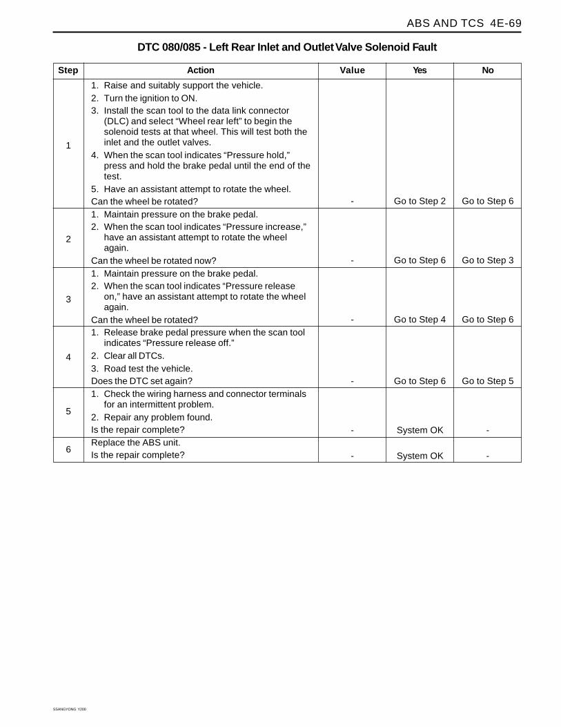
Step
1. Raise and suitably support the vehicle.2. Turn the ignition to ON.3. Install the scan tool to the data link connector
(DLC) and select “Wheel rear left” to begin thesolenoid tests at that wheel. This will test both theinlet and the outlet valves.
4. When the scan tool indicates “Pressure hold,”press and hold the brake pedal until the end of thetest.
5. Have an assistant attempt to rotate the wheel.Can the wheel be rotated?1. Maintain pressure on the brake pedal.2. When the scan tool indicates “Pressure increase,”
have an assistant attempt to rotate the wheelagain.
Can the wheel be rotated now?1. Maintain pressure on the brake pedal.2. When the scan tool indicates “Pressure release
on,” have an assistant attempt to rotate the wheelagain.
Can the wheel be rotated?1. Release brake pedal pressure when the scan tool
indicates “Pressure release off.”2. Clear all DTCs.3. Road test the vehicle.Does the DTC set again?1. Check the wiring harness and connector terminals
for an intermittent problem.2. Repair any problem found.Is the repair complete?Replace the ABS unit.Is the repair complete?
DTC 080/085 - Left Rear Inlet and Outlet Valve Solenoid Fault
1
Action Yes NoValue
2
3
Go to Step 2 Go to Step 6-
4
5
6
Go to Step 6 Go to Step 5-
System OK --
System OK --
Go to Step 6 Go to Step 3-
Go to Step 4 Go to Step 6-

SSANGYONG Y200
4E-70 ABS AND TCS
DIAGNOSTIC TROUBLE COED (DTC) 090/095 - RIGHT REAR INLET ANDOUTLET VALVE SOLENOID FAULT
Circuit Description
The solenoid valve coil circuits are supplied with powerfrom the battery when the valve relay is energized.Switched ground is provided by the electronic brakecontrol module (EBCM) to each coil.
Diagnosis
This procedure checks whether the right rear inlet andoutlet valves are functioning.
Cause(s)
• A valve has failed.
• A solenoid coil is open or shorted.
Action Taken When the DTC Sets
ABS is disabled, and the ABS warning lamp is turnedON for the remainder of the ignition cycle. If the failureis intermittent, the EBCM will enable the system at thenext ignition cycle and set a history DTC.
Test Description
The number(s) below refer to step(s) on the diagnostictable.
1. This begins the test of the inlet valve
3. This tests the outlet valve.
YAD4E230
ABS AND TCS 4E-71
SSANGYONG Y200
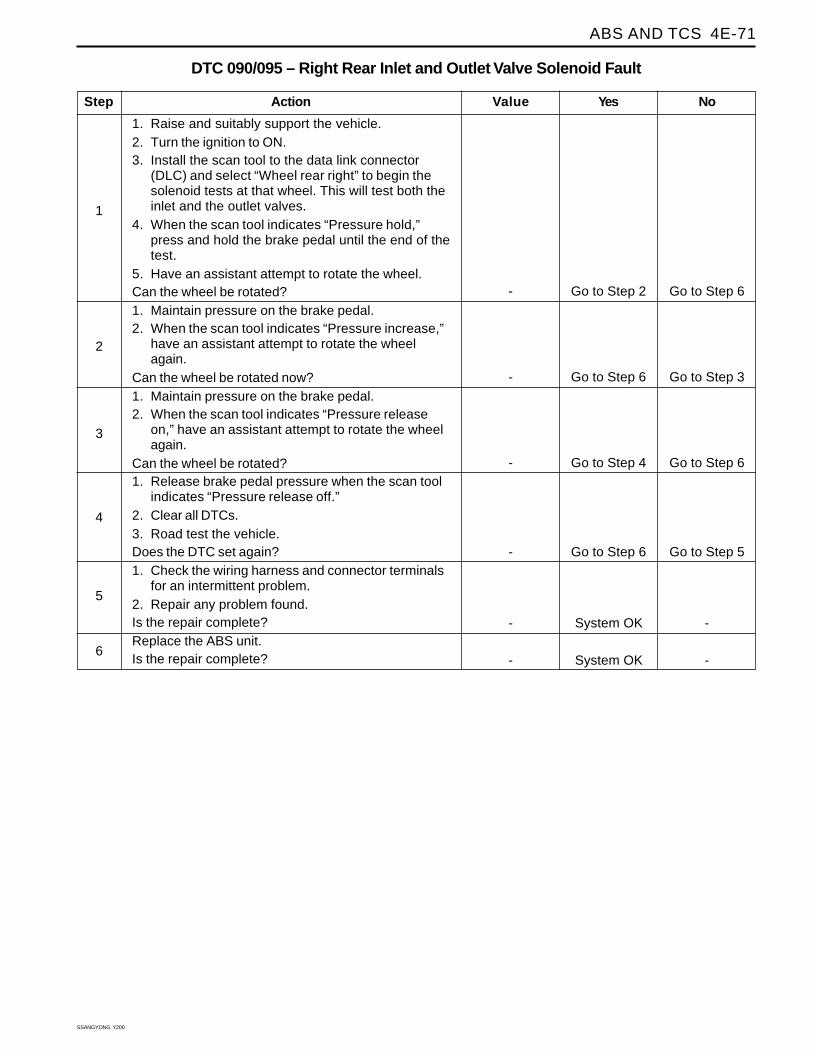
Step
1. Raise and suitably support the vehicle.2. Turn the ignition to ON.3. Install the scan tool to the data link connector
(DLC) and select “Wheel rear right” to begin thesolenoid tests at that wheel. This will test both theinlet and the outlet valves.
4. When the scan tool indicates “Pressure hold,”press and hold the brake pedal until the end of thetest.
5. Have an assistant attempt to rotate the wheel.Can the wheel be rotated?1. Maintain pressure on the brake pedal.2. When the scan tool indicates “Pressure increase,”
have an assistant attempt to rotate the wheelagain.
Can the wheel be rotated now?1. Maintain pressure on the brake pedal.2. When the scan tool indicates “Pressure release
on,” have an assistant attempt to rotate the wheelagain.
Can the wheel be rotated?1. Release brake pedal pressure when the scan tool
indicates “Pressure release off.”2. Clear all DTCs.3. Road test the vehicle.Does the DTC set again?1. Check the wiring harness and connector terminals
for an intermittent problem.2. Repair any problem found.Is the repair complete?Replace the ABS unit.Is the repair complete?
DTC 090/095 – Right Rear Inlet and Outlet Valve Solenoid Fault
1
Action Yes NoValue
2
3
Go to Step 2 Go to Step 6-
4
5
6
Go to Step 6 Go to Step 5-
System OK --
System OK --
Go to Step 6 Go to Step 3-
Go to Step 4 Go to Step 6-