Embed Size (px)
Citation preview
Diagnostic X-Ray ShieldingMulti-Slice CT Scanners
Using NCRP 147 Methodology
Diagnostic X-Ray ShieldingMulti-Slice CT Scanners
Using NCRP 147 Methodology
Melissa C. Martin, M.S., FAAPM, FACRTherapy Physics Inc., Bellflower, CA
AAPM Annual Meeting, Orlando, FLRefresher Course
Thursday, August 3, 2006 8:30 am
Melissa C. Martin, M.S., FAAPM, FACRTherapy Physics Inc., Bellflower, CA
AAPM Annual Meeting, Orlando, FLRefresher Course
Thursday, August 3, 2006 8:30 am
AcknowledgementAcknowledgement
Slides Courtesy of:Slides Courtesy of:
S. Jeff S. Jeff ShephardShephard, M.S., DABR, M.S., DABRM.D. Anderson Cancer Center, Houston, TXM.D. Anderson Cancer Center, Houston, TX
Ben Archer, Ben Archer, Ph.DPh.D, FACR, FACRBaylor College of Medicine, Houston, TXBaylor College of Medicine, Houston, TX
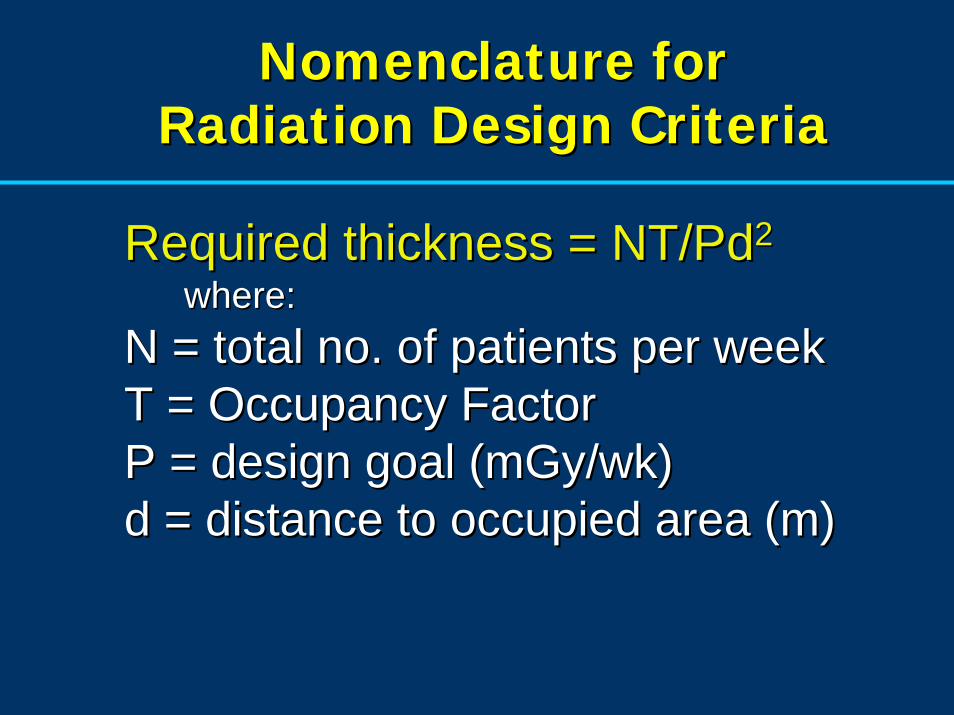
Nomenclature for Radiation Design Criteria
Nomenclature for Nomenclature for Radiation Design CriteriaRadiation Design Criteria
Required thickness = NT/PdRequired thickness = NT/Pd22
where: where: N = total no. of patients per weekN = total no. of patients per weekT = Occupancy FactorT = Occupancy FactorP = design goal (P = design goal (mGymGy/wk)/wk)d = distance to occupied area (m)d = distance to occupied area (m)
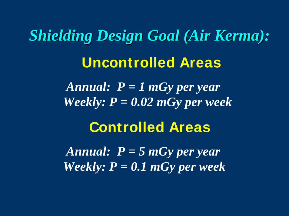
Shielding Design Goal (Air Kerma):
Uncontrolled Areas
Annual: P = 1 mGy per year Weekly: P = 0.02 mGy per week
Controlled Areas
Annual: P = 5 mGy per year Weekly: P = 0.1 mGy per week
Shielding Design Goal (Air Shielding Design Goal (Air KermaKerma):):
Uncontrolled Areas
Annual: P = 1 mGy per year Weekly: P = 0.02 mGy per week
Controlled Areas
Annual: P = 5 mGy per year Weekly: P = 0.1 mGy per week
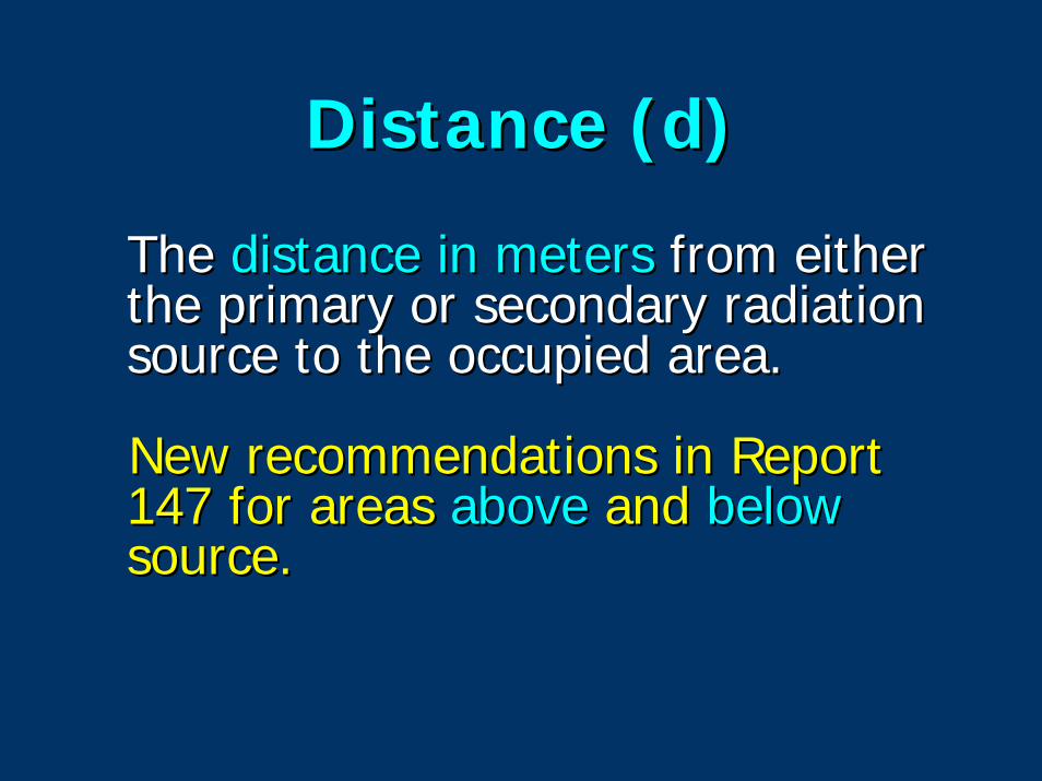
Distance (d)Distance (d)
The The distance in metersdistance in meters from either from either the primary or secondary radiation the primary or secondary radiation source to the occupied area.source to the occupied area.
New recommendations in Report New recommendations in Report 147 for areas 147 for areas aboveabove and and belowbelowsource.source.
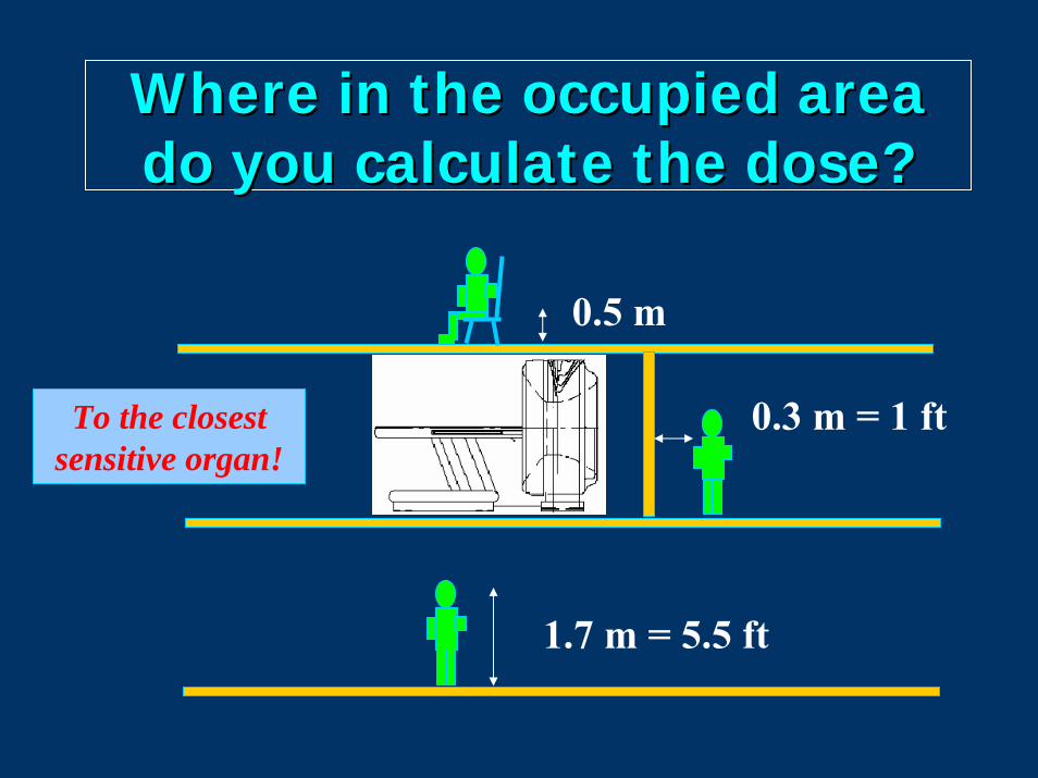
Where in the occupied area Where in the occupied area do you calculate the dose?do you calculate the dose?
0.5 m
To the closest sensitive organ!
0.3 m = 1 ft
1.7 m = 5.5 ft
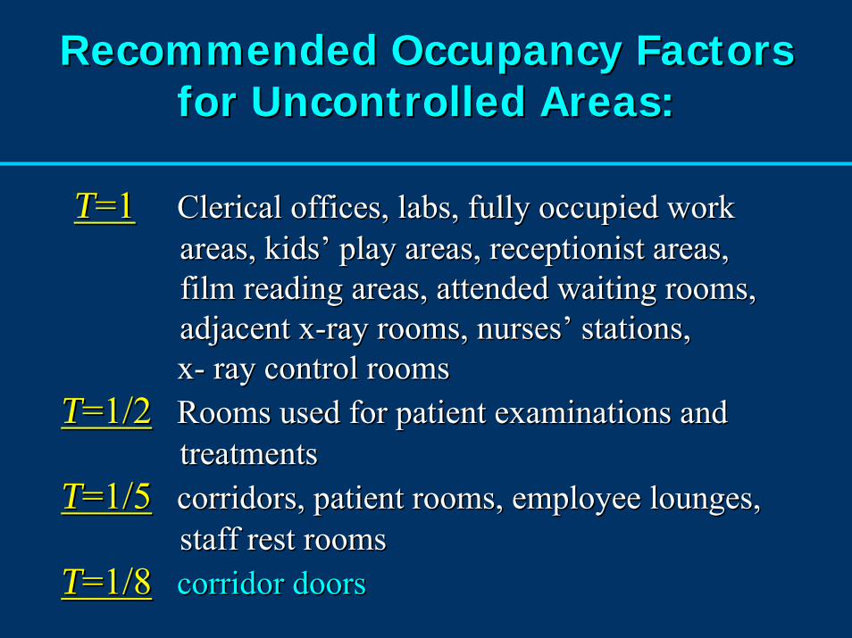
Recommended Occupancy Factors Recommended Occupancy Factors for Uncontrolled Areas:for Uncontrolled Areas:
TT=1=1 Clerical offices, labs, fully occupied work Clerical offices, labs, fully occupied work areas, kids’ play areas, receptionist areas, areas, kids’ play areas, receptionist areas, film reading areas, attended waiting rooms, film reading areas, attended waiting rooms, adjacent xadjacent x--ray rooms, nurses’ stations, ray rooms, nurses’ stations, xx-- ray control roomsray control rooms
TT=1/2=1/2 Rooms used for patient examinations and Rooms used for patient examinations and treatmentstreatments
TT=1/5=1/5 corridors, patient rooms, employee lounges, corridors, patient rooms, employee lounges, staff rest rooms staff rest rooms
TT=1/8=1/8 corridor doorscorridor doors
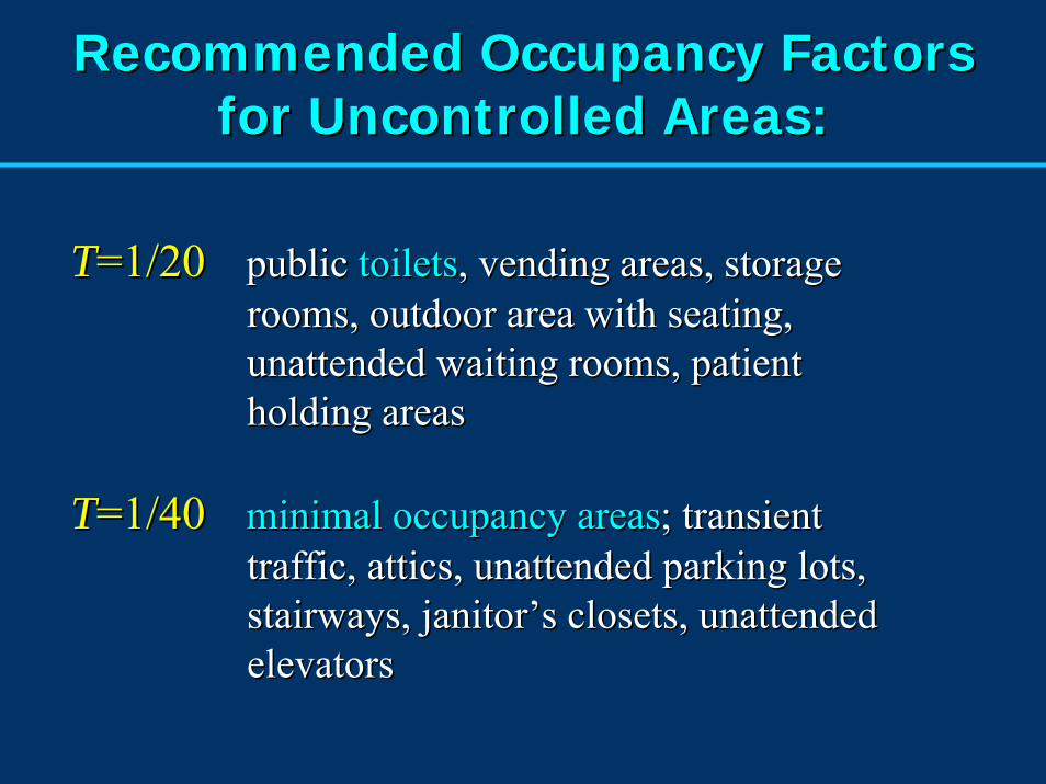
Recommended Occupancy FactorsRecommended Occupancy Factorsfor Uncontrolled Areas:for Uncontrolled Areas:
TT=1/20=1/20 public public toiletstoilets, vending areas, storage , vending areas, storage rooms, outdoor area with seating, rooms, outdoor area with seating, unattended waiting rooms, patient unattended waiting rooms, patient holding areasholding areas
TT=1/40=1/40 minimal occupancy areasminimal occupancy areas; transient ; transient traffic, attics, unattended parking lots, traffic, attics, unattended parking lots, stairways, janitor’s closets, unattended stairways, janitor’s closets, unattended elevatorselevators
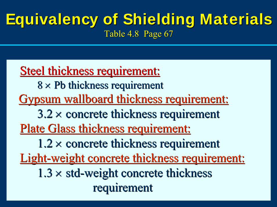
Equivalency of Shielding Materials Equivalency of Shielding Materials Table 4.8 Page 67Table 4.8 Page 67
Steel thickness requirement:Steel thickness requirement:8 8 ×× PbPb thickness requirementthickness requirement
Gypsum wallboard thickness requirement:Gypsum wallboard thickness requirement:3.2 3.2 ×× concrete thickness requirementconcrete thickness requirement
Plate Glass thickness requirement:Plate Glass thickness requirement:1.2 1.2 ×× concrete thickness requirementconcrete thickness requirement
LightLight--weight concrete thickness requirement:weight concrete thickness requirement:1.3 1.3 ×× stdstd--weight concrete thickness weight concrete thickness
requirementrequirement
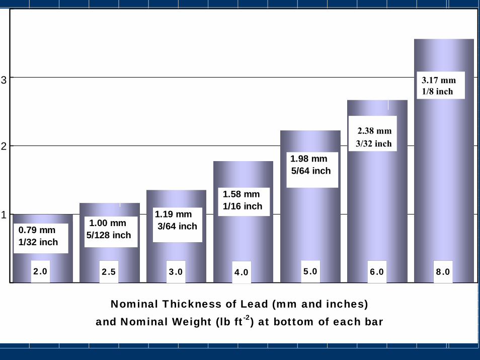
3.02.0 2.5 4.0 5.0 6.0 8.0
Nominal Thickness of Lead (mm and inches) and Nominal Weight (lb ft-2) at bottom of each bar
0.79 mm 1/32 inch
1.00 mm5/128 inch
1.19 mm 3/64 inch
1.58 mm 1/16 inch
1.98 mm 5/64 inch
23
1
2
3 3.17 mm1/8 inch
2.38 mm3/32 inch
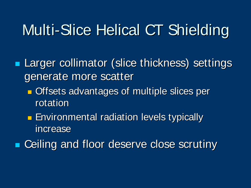
MultiMulti--Slice Helical CT ShieldingSlice Helical CT Shielding
Larger collimator (slice thickness) settings Larger collimator (slice thickness) settings generate more scattergenerate more scatter
Offsets advantages of multiple slices per Offsets advantages of multiple slices per rotationrotationEnvironmental radiation levels typically Environmental radiation levels typically increaseincrease
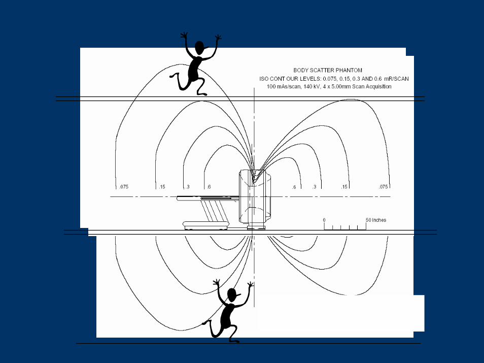
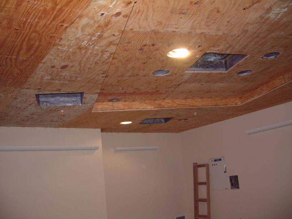
Ceiling and floor deserve close scrutinyCeiling and floor deserve close scrutiny

ProblemProblem
Question:Question:Do I really need to put lead in Do I really need to put lead in the ceiling of a 16the ceiling of a 16--slice CT slice CT scanner room?scanner room?
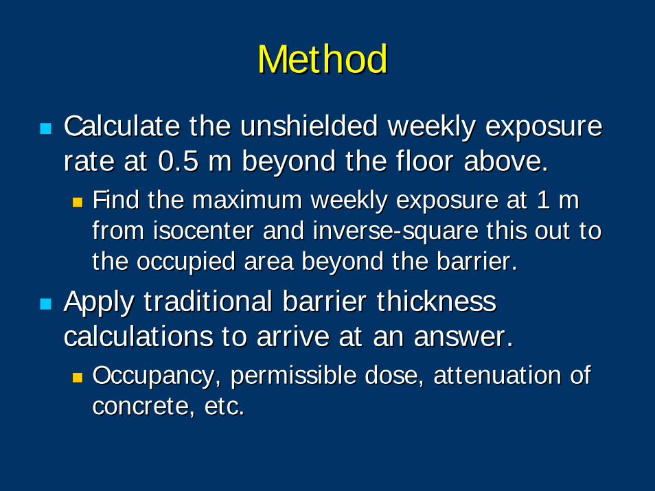
MethodMethod
Calculate the unshielded weekly exposure Calculate the unshielded weekly exposure rate at 0.5 m beyond the floor above.rate at 0.5 m beyond the floor above.
Find the maximum weekly exposure at 1 m Find the maximum weekly exposure at 1 m from from isocenterisocenter and inverseand inverse--square this out to square this out to the occupied area beyond the barrier.the occupied area beyond the barrier.
Apply traditional barrier thickness Apply traditional barrier thickness calculations to arrive at an answer.calculations to arrive at an answer.
Occupancy, permissible dose, attenuation of Occupancy, permissible dose, attenuation of concrete, etc.concrete, etc.
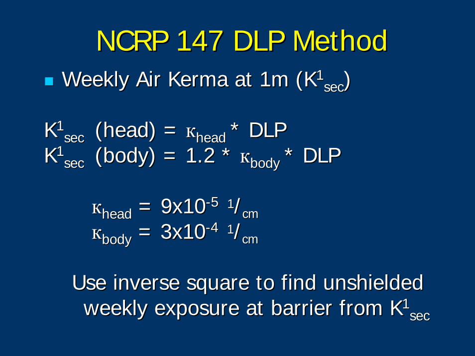
NCRP 147 DLP MethodNCRP 147 DLP MethodWeekly Air Kerma at 1m (KWeekly Air Kerma at 1m (K11
secsec))
KK11sec sec (head) = (head) = ккheadhead * DLP* DLP
KK11sec sec (body) = 1.2 * (body) = 1.2 * ккbodybody * DLP* DLP
ккheadhead = 9x10= 9x10--5 5 11//cmcm
ккbodybody = 3x10= 3x10--4 4 11//cmcm
Use inverse square to find unshielded Use inverse square to find unshielded weekly exposure at barrier from Kweekly exposure at barrier from K11
secsec
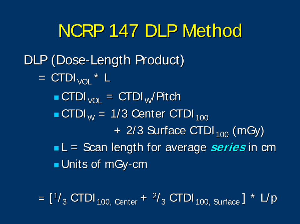
NCRP 147 DLP MethodNCRP 147 DLP MethodDLP (DoseDLP (Dose--Length Product) Length Product)
= CTDI= CTDIVOL VOL * L * L
CTDICTDIVOLVOL = CTDI= CTDIWW/Pitch/PitchCTDICTDIWW = 1/3 Center CTDI= 1/3 Center CTDI100100
+ 2/3 Surface CTDI+ 2/3 Surface CTDI100100 (mGy)(mGy)L = Scan length for average L = Scan length for average seriesseries in cmin cmUnits of mGyUnits of mGy--cmcm
= = [[11//33 CTDICTDI100, Center 100, Center + + 22//33 CTDICTDI100, Surface 100, Surface ] * L/p] * L/p
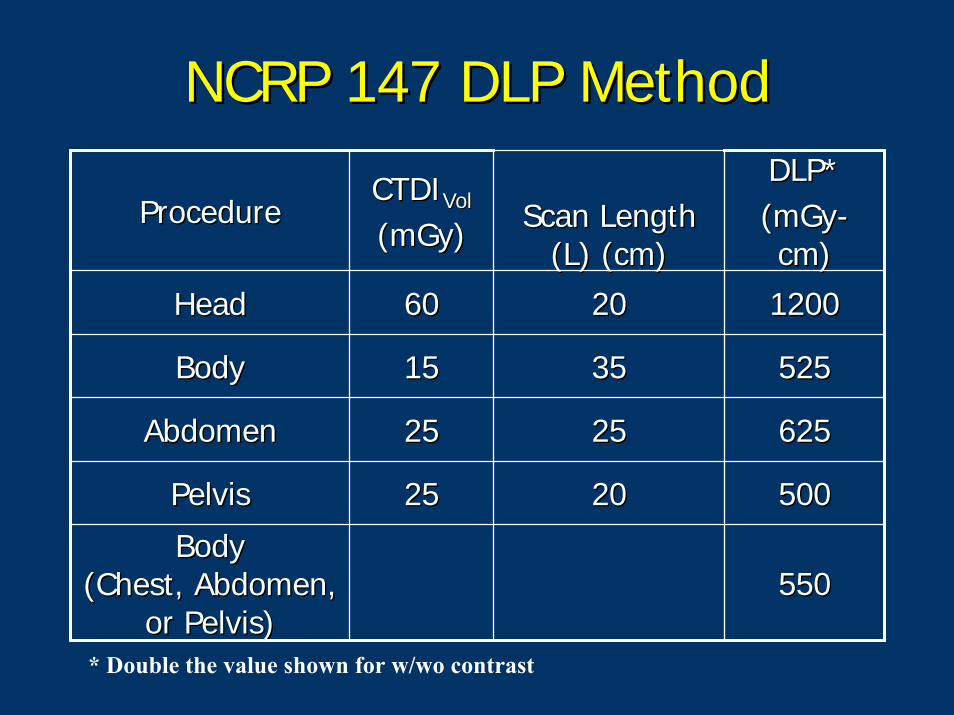
NCRP 147 DLP MethodNCRP 147 DLP Method
ProcedureProcedureCTDICTDIVolVol
(mGy)(mGy) Scan Length Scan Length (L) (cm)(L) (cm)
DLP*DLP*(mGy(mGy--cm)cm)
HeadHead 6060 2020 12001200
BodyBody 1515 3535 525525
AbdomenAbdomen 2525 2525 625625
PelvisPelvis 2525 2020 500500
BodyBody(Chest, Abdomen, (Chest, Abdomen,
or Pelvis)or Pelvis)550550
* Double the value shown for w/wo contrast
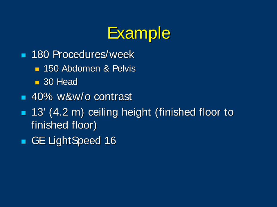
ExampleExample180 Procedures/week180 Procedures/week
150 Abdomen & Pelvis150 Abdomen & Pelvis30 Head 30 Head
40% w&w/o contrast40% w&w/o contrast13’ (4.2 m) ceiling height (finished floor to 13’ (4.2 m) ceiling height (finished floor to finished floor)finished floor)GE GE LightSpeedLightSpeed 1616
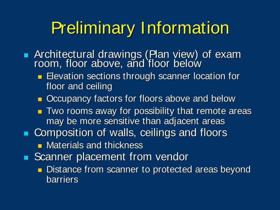
Preliminary InformationPreliminary InformationArchitectural drawings (Plan view) of exam Architectural drawings (Plan view) of exam room, floor above, and floor belowroom, floor above, and floor below
Elevation sections through scanner location for Elevation sections through scanner location for floor and ceilingfloor and ceilingOccupancy factors for floors above and belowOccupancy factors for floors above and belowTwo rooms away for possibility that remote areas Two rooms away for possibility that remote areas may be more sensitive than adjacent areas may be more sensitive than adjacent areas
Composition of walls, ceilings and floorsComposition of walls, ceilings and floorsMaterials and thicknessMaterials and thickness
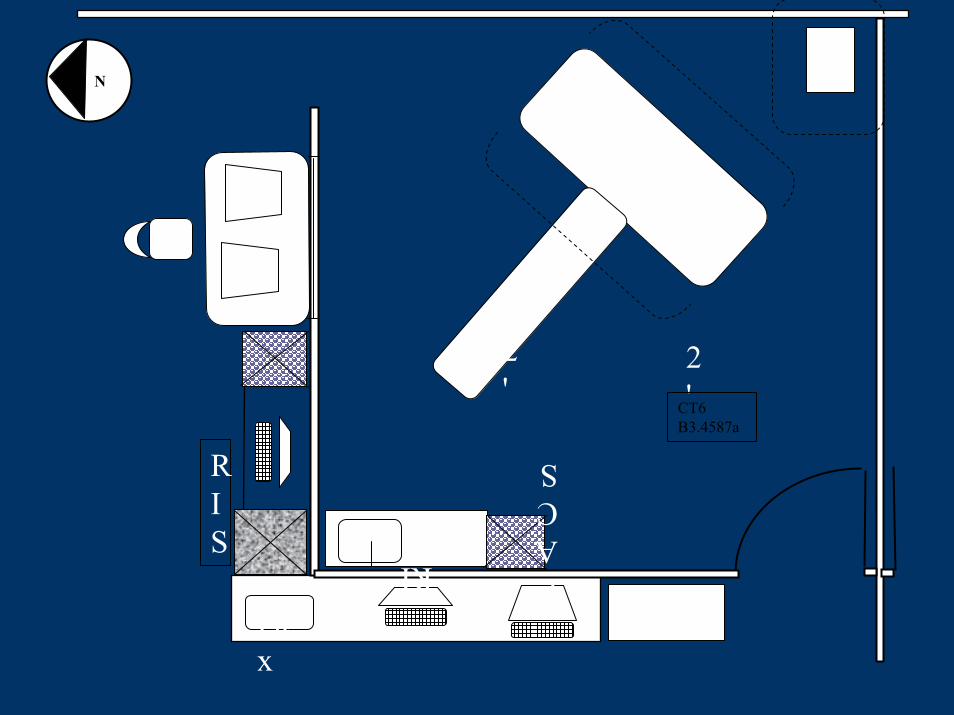
Scanner placement from vendorScanner placement from vendorDistance from scanner to protected areas beyond Distance from scanner to protected areas beyond barriersbarriers
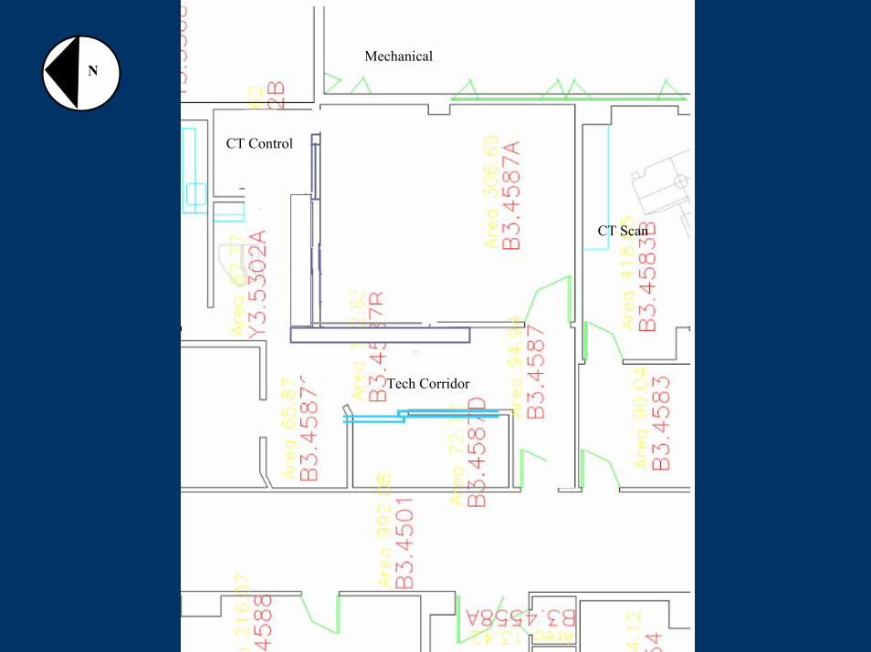
Mechanical
Tech Corridor
CT Control
NN
CT Scan
CopyFax
PACS
RIS
RIS
12'
2'
NN
CT6B3.4587a
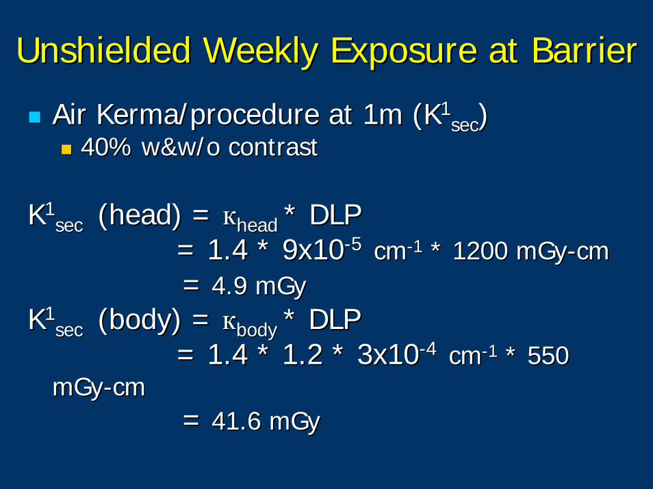
Unshielded Weekly Exposure at BarrierUnshielded Weekly Exposure at Barrier
Air Air KermaKerma/procedure at 1m (K/procedure at 1m (K11secsec))
40% w&w/o contrast40% w&w/o contrast
KK11sec sec (head) = (head) = ккheadhead * DLP* DLP
= 1.4 * 9x10= 1.4 * 9x10--5 5 cmcm--11 * 1200 * 1200 mGymGy--cmcm== 4.9 4.9 mGymGy
KK11sec sec (body) = (body) = ккbodybody * DLP* DLP
= 1.4 * 1.2 * 3x10= 1.4 * 1.2 * 3x10--4 4 cmcm--11 * 550 * 550 mGymGy--cmcm
== 41.6 41.6 mGymGy
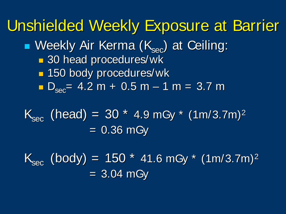
Unshielded Weekly Exposure at BarrierUnshielded Weekly Exposure at BarrierWeekly Air Kerma (Weekly Air Kerma (KKsecsec) at Ceiling:) at Ceiling:
30 head procedures/wk30 head procedures/wk150 body procedures/wk150 body procedures/wkDDsecsec= 4.2 m + 0.5 m = 4.2 m + 0.5 m –– 1 m = 3.7 m1 m = 3.7 m
KKsecsec (head) = 30 * (head) = 30 * 4.9 4.9 mGymGy * (1m/3.7m)* (1m/3.7m)22
= 0.36 = 0.36 mGymGy
KKsecsec (body) = 150 * (body) = 150 * 41.6 41.6 mGymGy * (1m/3.7m)* (1m/3.7m)22
= 3.04 = 3.04 mGymGy
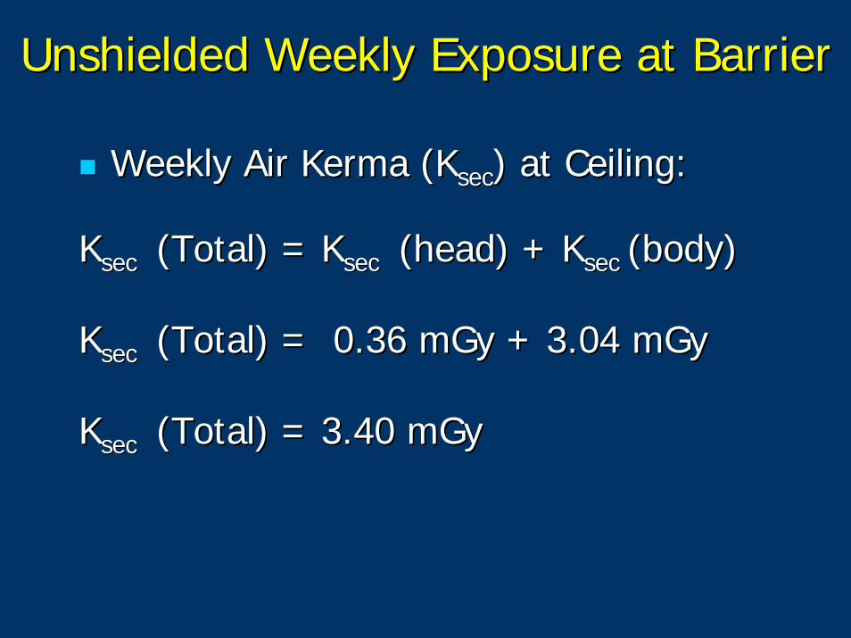
Unshielded Weekly Exposure at BarrierUnshielded Weekly Exposure at Barrier
Weekly Air Kerma (Weekly Air Kerma (KKsecsec) at Ceiling:) at Ceiling:
KKsecsec (Total) = (Total) = KKsecsec (head) + (head) + KKsecsec (body)(body)
KKsecsec (Total) = 0.36 (Total) = 0.36 mGymGy + 3.04 + 3.04 mGymGy
KKsecsec (Total) = 3.40 (Total) = 3.40 mGymGy
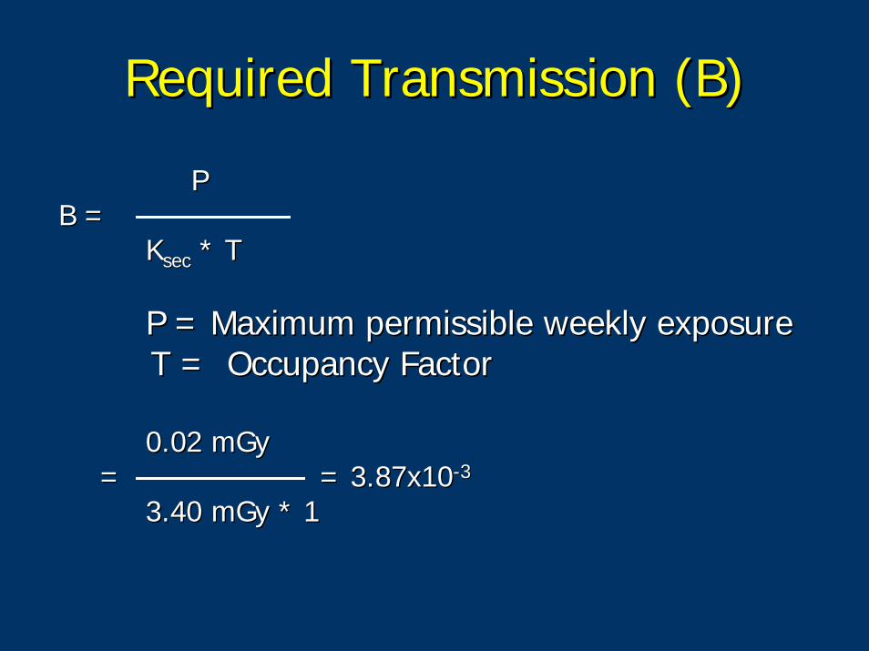
Required Transmission (B)Required Transmission (B)
PPB =B =
KKsecsec * T* T
P = Maximum permissible weekly exposureP = Maximum permissible weekly exposureT = Occupancy FactorT = Occupancy Factor
0.02 0.02 mGymGy= = = 3.87x10= 3.87x10--33
3.40 3.40 mGymGy * 1* 1
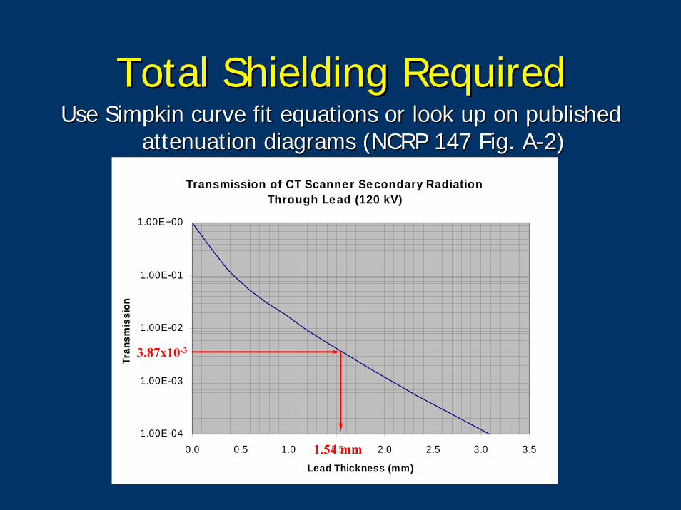
Total Shielding RequiredTotal Shielding RequiredUse Use SimpkinSimpkin curve fit equations or look up on published curve fit equations or look up on published
attenuation diagrams (NCRP 147 Fig. Aattenuation diagrams (NCRP 147 Fig. A--2)2)
Transmission of CT Scanner Secondary RadiationThrough Lead (120 kV)
1.00E-04
1.00E-03
1.00E-02
1.00E-01
1.00E+00
0.0 0.5 1.0 1.5 2.0 2.5 3.0 3.5
Lead Thickness (mm)
Tran
smis
sion
3.87x10⁻³
1.54 mm
Existing ShieldingExisting ShieldingMeasure existing attenuation in walls with TcMeasure existing attenuation in walls with Tc--99m source and Na99m source and Na--I detector (determine leadI detector (determine lead--equivalence equivalence –– usually 0.1 mm usually 0.1 mm PbPb--eqeq))Floors and ceilingsFloors and ceilings
Find lead equivalence from documentation of Find lead equivalence from documentation of concrete thickness.concrete thickness.Find thickness by drilling a test hole and measuring.Find thickness by drilling a test hole and measuring.Always assume light weight concrete, unless proven Always assume light weight concrete, unless proven otherwise (30% less dense than standard density, otherwise (30% less dense than standard density, coefficients used in NCRP 147)coefficients used in NCRP 147)
Transmission of CT Scanner Secondary RadiationThrough Lead (120 kV)
1.00E-04
1.00E-03
1.00E-02
1.00E-01
1.00E+00
0.0 0.5 1.0 1.5 2.0 2.5 3.0 3.5
Lead Thickness (mm)
Tran
smis
sion
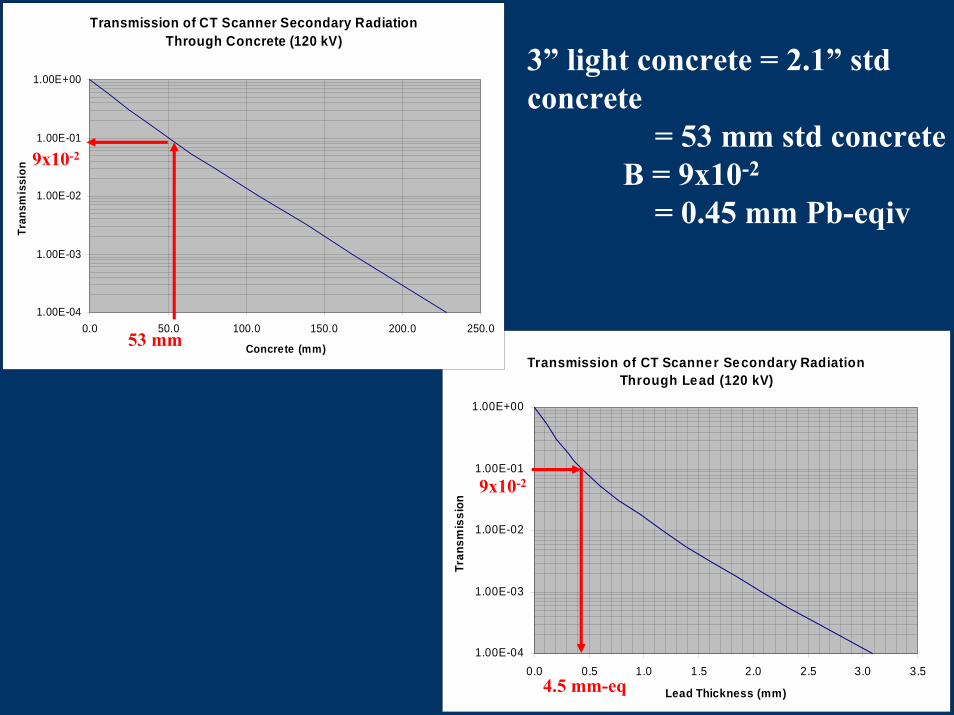
Transmission of CT Scanner Secondary RadiationThrough Concrete (120 kV)
1.00E-04
1.00E-03
1.00E-02
1.00E-01
1.00E+00
0.0 50.0 100.0 150.0 200.0 250.0
Concrete (mm)
Tran
smis
sion
3” light concrete = 2.1” std concrete
= 53 mm std concreteB = 9x10-2
= 0.45 mm Pb-eqiv
53 mm
9x10⁻²
4.5 mm-eq
9x10⁻²
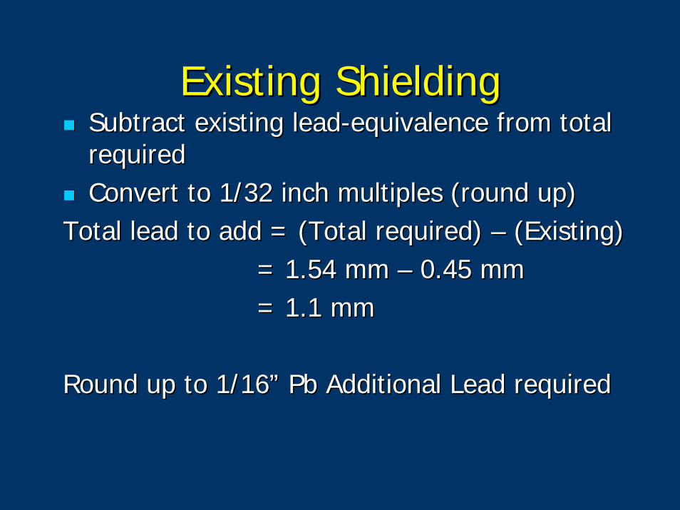
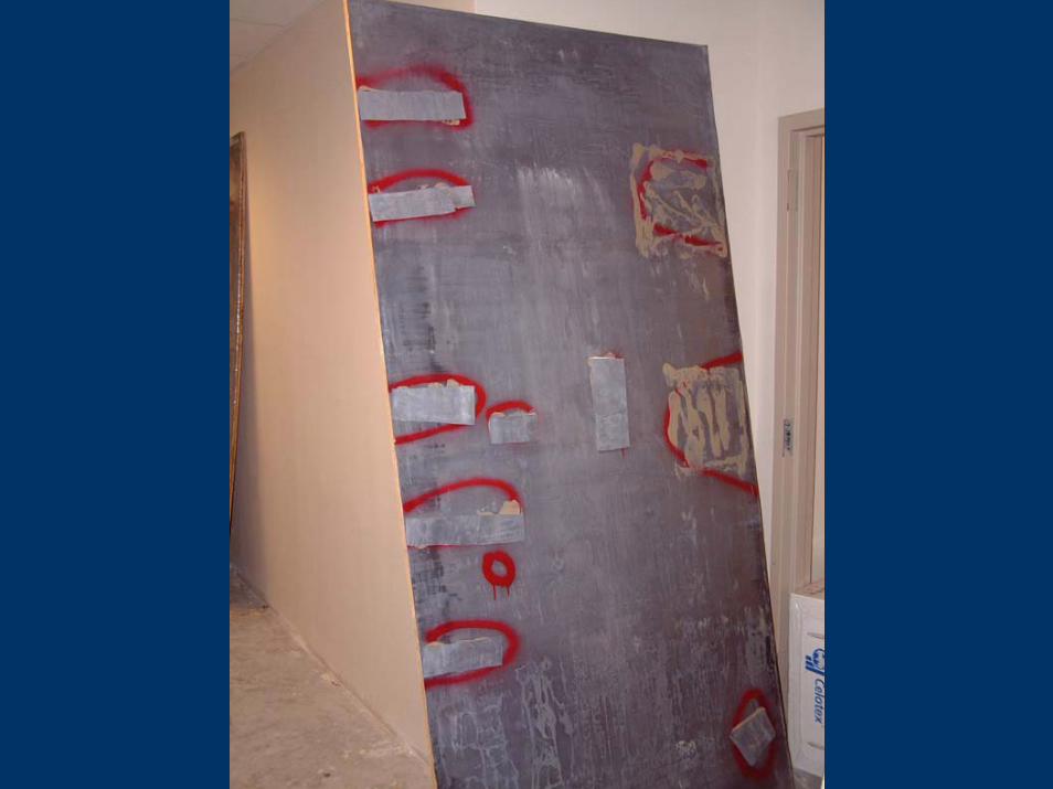
Existing ShieldingExisting ShieldingSubtract existing leadSubtract existing lead--equivalence from total equivalence from total requiredrequiredConvert to 1/32 inch multiples (round up)Convert to 1/32 inch multiples (round up)
Total lead to add = (Total required) Total lead to add = (Total required) –– (Existing)(Existing)= 1.54 mm = 1.54 mm –– 0.45 mm0.45 mm= 1.1 mm= 1.1 mm
Round up to 1/16” Round up to 1/16” PbPb Additional Lead requiredAdditional Lead required
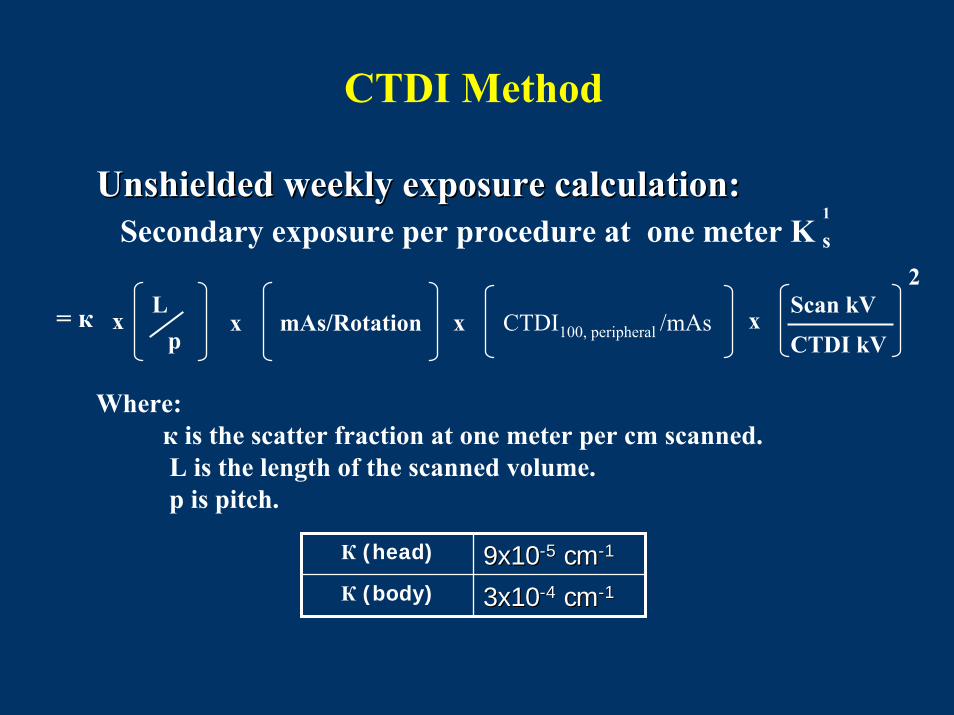
CTDI Method
x CTDI100, peripheral /mAs
Unshielded weekly exposure calculation:Unshielded weekly exposure calculation:
x mAs/Rotation
Secondary exposure per procedure at one meter K s1
Scan kV
CTDI kVx
2L
px= к
Where:к is the scatter fraction at one meter per cm scanned.L is the length of the scanned volume.p is pitch.
К (head) 9x109x10--55 cmcm--11
К (body) 3x103x10--44 cmcm--11
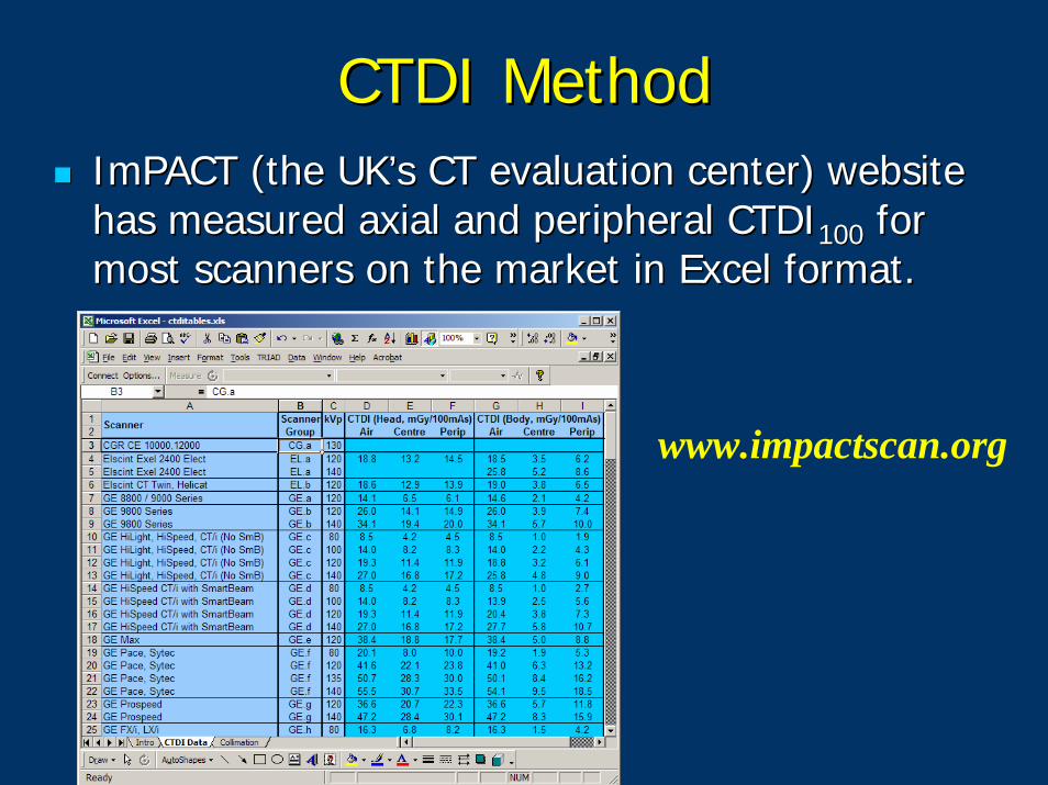
CTDI MethodCTDI MethodImPACTImPACT (the UK’s CT evaluation center)(the UK’s CT evaluation center) website website has measured axial and peripheral CTDIhas measured axial and peripheral CTDI100100 for for most scanners on the market in Excel format. most scanners on the market in Excel format.
www.impactscan.org

CTDI Method
Calculate K sec for head and body separately, then combine with weighting factors depending on percentage of total workload.
% heads * Ks (head) + % body * Ks (body)Ks (total) =
100%
Finally, inverse-square this exposure out to each area to be protected.
1
1
1 1
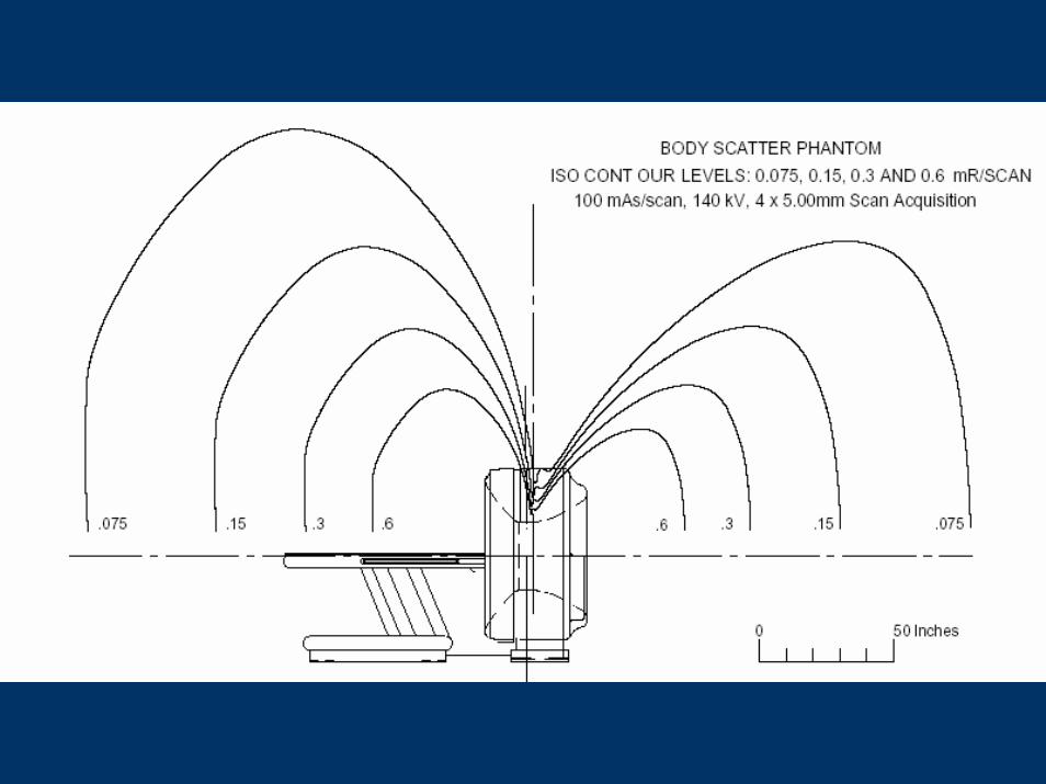
IsodoseIsodose Map MethodMap Method
Assume an isotropic exposure distribution Assume an isotropic exposure distribution based on the maximum exposure rate in based on the maximum exposure rate in the vendorthe vendor--supplied exposure distribution supplied exposure distribution plots (approx. 45plots (approx. 45oo to the scanner axis).to the scanner axis).Overestimates shielding needed in the Overestimates shielding needed in the gantry shadows and the shadows of the gantry shadows and the shadows of the patient.patient.
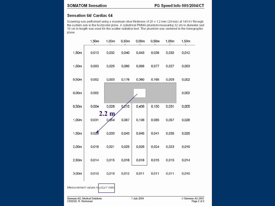
2.2 m
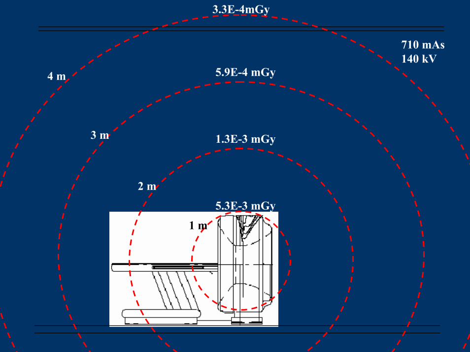
1.3E-3 mGy
5.9E-4 mGy
5.3E-3 mGy
710 mAs140 kV
3.3E-4mGy
1 m
4 m
3 m
2 m
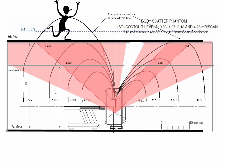
8th floor
Acceptable exposuresoutside of this line
9’
7th floor
Lead
Lead
12'
Drop Ceiling
Lead
Lead
0.5 m aff
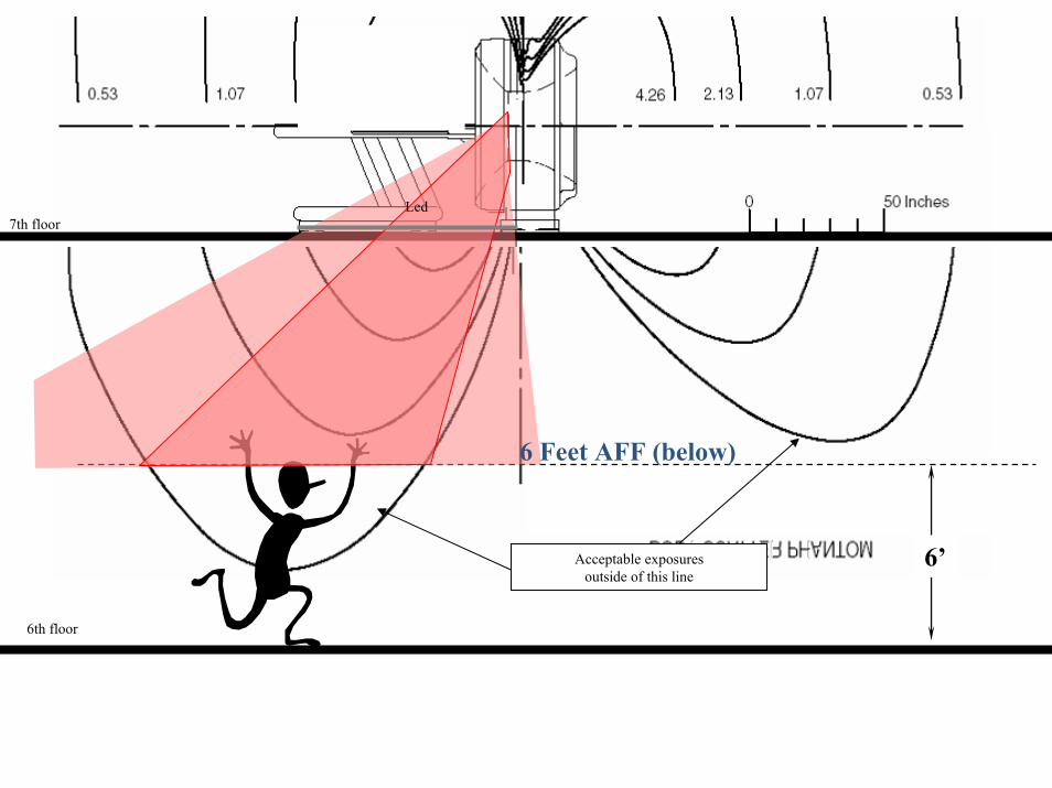
Acceptable exposuresoutside of this line
6th floor
7th floor
6’
Led
6 Feet AFF (below)
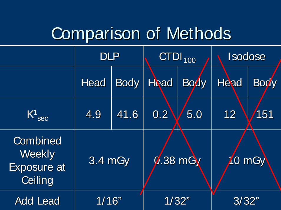
Comparison of MethodsComparison of MethodsDLPDLP CTDICTDI100100 IsodoseIsodose
HeadHead BodyBody HeadHead
0.20.2
Combined Combined Weekly Weekly
Exposure at Exposure at CeilingCeiling
3.4 3.4 mGymGy 0.38 0.38 mGymGy 10 10 mGymGy
Add LeadAdd Lead 1/16”1/16” 1/32”1/32” 3/32”3/32”
BodyBody HeadHead BodyBody
KK11secsec 4.94.9 41.641.6 5.05.0 1212 151151
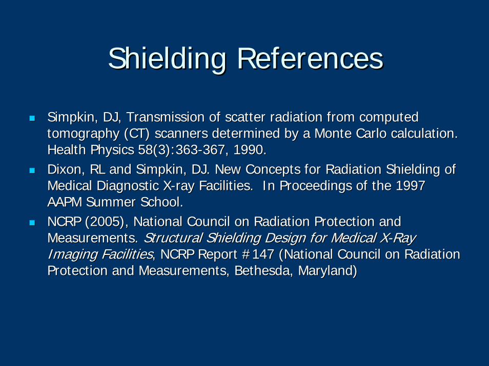
Shielding ReferencesShielding References
SimpkinSimpkin, DJ, Transmission of scatter radiation from computed , DJ, Transmission of scatter radiation from computed tomography (CT) scanners determined by a Monte Carlo calculationtomography (CT) scanners determined by a Monte Carlo calculation. . Health Physics 58(3):363Health Physics 58(3):363--367, 1990.367, 1990.Dixon, RL and Dixon, RL and SimpkinSimpkin, DJ. New Concepts for Radiation Shielding of , DJ. New Concepts for Radiation Shielding of Medical Diagnostic XMedical Diagnostic X--ray Facilities. In Proceedings of the 1997 ray Facilities. In Proceedings of the 1997 AAPM Summer School.AAPM Summer School.NCRP (2005), National Council on Radiation Protection and NCRP (2005), National Council on Radiation Protection and Measurements. Measurements. Structural Shielding Design for Medical XStructural Shielding Design for Medical X--Ray Ray Imaging FacilitiesImaging Facilities, NCRP Report #147 (National Council on Radiation , NCRP Report #147 (National Council on Radiation Protection and Measurements, Bethesda, Maryland)Protection and Measurements, Bethesda, Maryland)
Contact InformationContact InformationMelissa C. Martin, M.S., FACR, FAAPMMelissa C. Martin, M.S., FACR, FAAPMCertified Medical PhysicistCertified Medical PhysicistTherapy Physics Inc.Therapy Physics Inc.9156 Rose St., Bellflower, CA 907069156 Rose St., Bellflower, CA 90706Office Phone: 562Office Phone: 562--804804--06110611Office Fax: 562Office Fax: 562--804804--06100610Cell Phone: 310Cell Phone: 310--612612--81278127EE--mail: mail: [email protected]@Compuserve.com