Embed Size (px)
Citation preview
www. dosonline.org l 49
Diagnostics
Corneal Topography
Diagnostics
Aditi ManudhaneMS
Aditi Manudhane MS, Ritu Arora MD, DNB, J.L.Goyal MD, DNB, Parul Jain MS, Gaurav Goyal MS
Guru Nanak Eye Centre, New Delhi
The cornea is the most important refractive element of the human eye, providing approximately two thirds
of its optical power. Detailed examination of the corneal curvature is an essential part of the workup before refractive surgery1, for fitting of contact lens and for diagnosis and management of ectatic disorders. Keratometry was one of the earliest methods for measuring corneal shape. However, it gives limited information about corneal shape and appreciates only gross amount of astigmatism. These limitations led to the development of more advanced techniques for evaluating corneal shape.
Three types of systems are used to measure corneal topography: Placido based, elevation based and interferometric. Recently Scheimpflug imaging has become increasingly popular.
Placido based systems: The handheld Klein keratoscope and Placido disc enable observation of reflections of multiple concentric circles from the corneal surface. The reflective mires appear closer together on steeper parts of the cornea and farther apart in flatter areas. Localized changes, such as tight sutures after a corneal transplant, will cause distortion of the mires in the area of suture compression. Currently available videokeratoscopes are- Eye MapEH -290 (Alcon), EMS (Zeiss) and Keraton Videokeratoscope (Optikon).
Limitations of the placido based system are:
o Difficulty to acquire data points within the central 2 mm of the cornea
o Imaging objects with sudden slope transitions, alignment, focusing or centration errors.
Elevation Based Systems: This method enables measurement of both anterior and posterior corneal surface2. Currently, two systems measure corneal elevation directly: PAR Corneal Topography System (CTS; PAR Vision Systems Corp., New Hartford, NY) and Accugrid and Orbtek Orbscan (Bausch and Lomb). The curvature
data are directly calculated from the elevation data without approximations3.Rasterphotogrammetry: The PAR Corneal Topography System was the first topography system to produce an elevation map of the corneal surface4. The system projects a grid onto the corneal surface after instillation of fluorescein. Distortions in grid patterns are analysed to determine corneal elevation based on camera and grid projection angles. Eg- Euclid ET-800 (Euclid Systems corp.,NJ)Scanning Slit Imaging: The Orbtek Orbscan is based on the innovative principle of measuring the dimensions of a slit-scanning beam projected on the cornea. Using slit or parallelopiped methodology, the curvature of the anterior and posterior surface of the cornea can be assessed along with the anterior surface of the lens and iris. During the examination, the patient fixes on a light source, whose reflex is aligned with the instrument axis. Two scanning slit lamps project a series of 40 (20 from the left and 20 from the right) slit beams angled at 45 degrees to the right and left of the video axis. A “tracking system” attempts to minimize the influence of involuntary eye movement. The instrument’s software analyzes 240 data points per slit (total 9600 points) and calculates the corneal thickness and posterior surface of the entire cornea. Total duration of examination is 1.5 seconds. The newer version, Orbscan II (Orbtek, Inc.)5 incorporates a Placido-disk attachment to obtain curvature measurements directly. Thus, Orbscan II has the benefits of both placido-disc and slit scanning approaches of corneal topography. The most recent hardware upgrade is the Orbscan IIz with version 3.12 software. It is integrated with a Shack-Hartmann aberrometer in the Zyoptix workstation for evaluating patients of refractive surgery.
Interpretation of corneal topography (Table 1,2)Corneal topography is analysed using colour coded contour maps of corneal power with cool colours (green, blue) representing lower corneal powers and warm colours (orange, red) representing high corneal powers.
50 l DOS Times - Vol. 19, No. 4 October, 2013
Diagnostics
Curvature/power map
Axial curvature/sagittal curvature: It is calculated by measuring the perpendicular distance from the tangent at a point to the sagittal (optical) axis.
Meridional curvature/tangential and instantaneous curvature - Tangential radius of curvature is calculated at each point with respect to its neighboring points by fitting the best-fit sphere (BFS). It gives better representation of local irregularity, than axial radius of curvature.
Elevation map
Corneal height or elevation is defined by the distance of each point on the corneal surface from a reference plane. Positive elevation measurement implies that the corneal surface falls above the reference plane and are interpreted as warm colours whereas negative values indicate that the corneal surface falls below the reference plane and are represented as cool colours on the elevation maps.
Analysis of Orbscan Quad map (Figure 1)1. Anterior float (Elevation best fit sphere)– The anterior
best fit sphere (BFS) is calculated to best match the anterior corneal surface. The elevation BFS map subtracts the calculated BFS against the eye surface in millimeters. The difference between the sphere and eye surface is expressed in radial distance from the centre of the sphere. Green is “sea level” (match with a sphere that best matches the cornea). Warmer colours are above sea-level,while cooler colours are below sea level.
2. Posterior float (Elevation best fit sphere) map– It describes the back surface of the cornea in the same manner as the anterior float but using posterior corneal measurements.
3. Keratometric (mean power) map– The keratometric map displays the refractive power of the anterior surface of the cornea and translates anterior curvature into corneal power.
4. Thickness (pachymetry) map– The pachymetry map demonstrates the corneal thickness through the entire cornea as well as the thinnest point of the cornea. Warm colours indicate thinner cornea while cooler colours indicate thicker corneas.
5. Anterior Chamber Depth and Anterior Iris–Lens Surface - When measuring mean anterior chamber depth (ACD) in phakic and pseudophakic eyes, Orbscan correlates well with US A-scan and has greater repeatability8-10.
Scheimpflug imagingThe Pentacam (Oculus Inc., Washington) obtains images of the anterior segment by a rotating Scheimpflug camera which is a digital CCD (Charged coupled device) camera with synchronous pixel sampling. The light source consists of UV-free blue LED’s (wavelength 475 nm). Imaging is based on the Scheimpflug principle, which occurs when a planar subject is not parallel to the image plane. With
Table 1
Absolute scale6 Normalised scale6
Preset colour scale with same diopteric steps.
Different color scales assigned to each map.
Minimum and maximum assigned to same colours
Instrument identifies actual minimal and maximal keratometric dioptric value of a particular cornea.
Larger increment in steps (0.5 D), so may miss subtle changes.
Range assigned to each colour is smaller, therefore it gives a more detailed description.
Table 2: Numerical and Statistical indices7
Simulated Keratometry (Sim K)
Maximum power of the surface along any axis and the power orthogonal to that axis (Sim K1 & Sim K2)
Mean values at central zone
Mean value at central 3 mm
Surface regularity index(SRI)
• Measures regularity in central 4.5 mm• Calculated from local power fluctuations along 256 equally spaced meridians on 10 central mires.• Zero for smooth surface, increases with increasing astigmatism.
Surface asymmetry Index (SAI)
Weighted summation of differences in corneal power between corresponding points 180 degree apart.0 for a perfect sphere
Potential visual acuity (PVA)
Estimation of the visual acuity considering cornea as the only factor limiting vision.
Asphericity • Described quantitatively by the Q value.• Q= 0 for a sphere• Q<0 for prolate surface• Q>0 for oblate surface• Normal cornea is prolate (ie, becomes flatter toward the periphery) and has Q value of -0.26.
www. dosonline.org l 51
Diagnostics
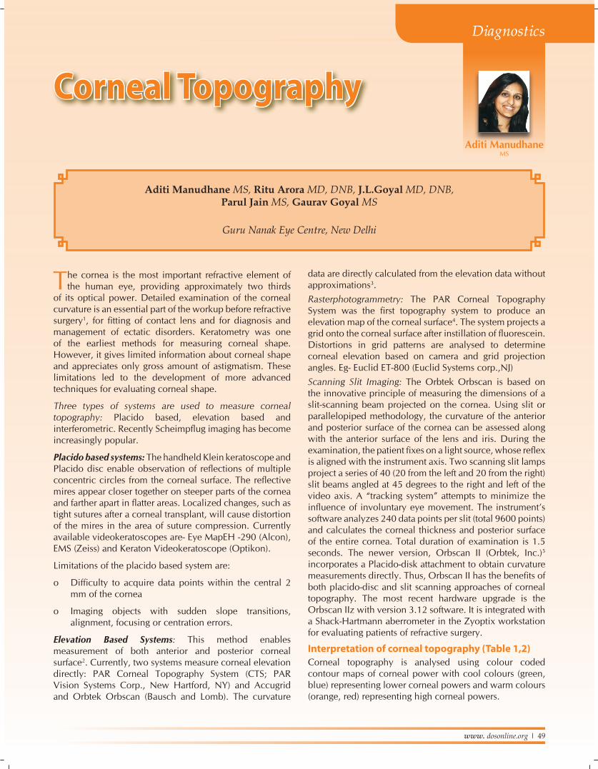
Figure 1: Analysis of orbscan Figure 2: Keratoconus
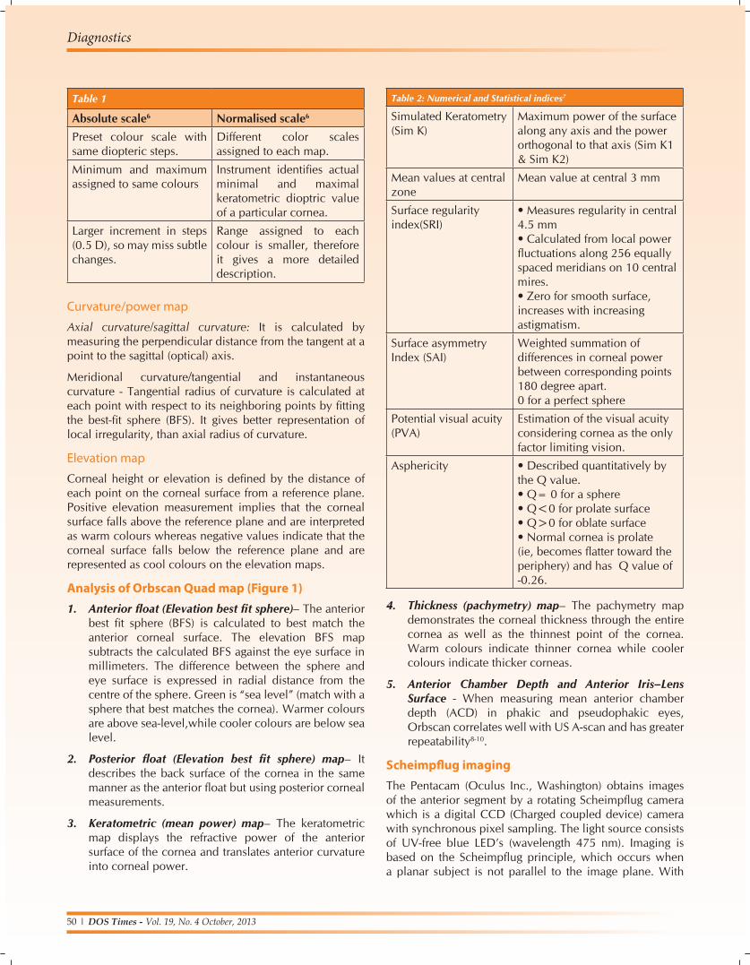
Figure 3: Pellucid marginal Degeneration
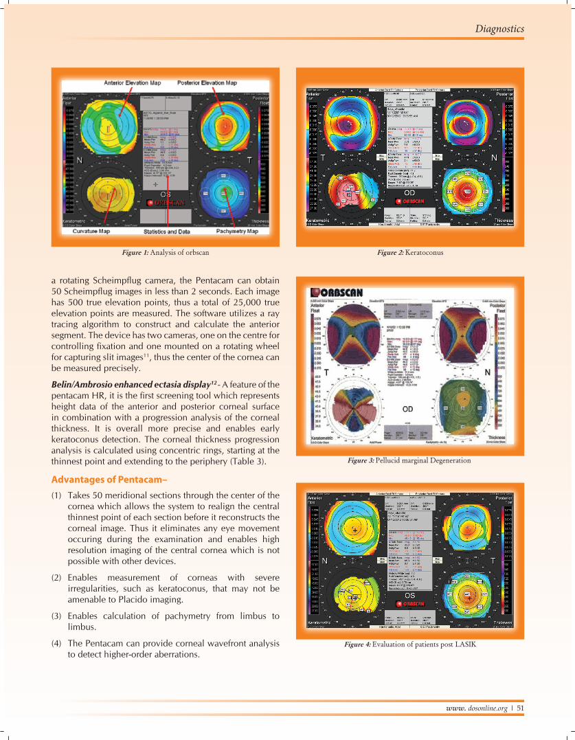
Figure 4: Evaluation of patients post LASIK
a rotating Scheimpflug camera, the Pentacam can obtain 50 Scheimpflug images in less than 2 seconds. Each image has 500 true elevation points, thus a total of 25,000 true elevation points are measured. The software utilizes a ray tracing algorithm to construct and calculate the anterior segment. The device has two cameras, one on the centre for controlling fixation and one mounted on a rotating wheel for capturing slit images11, thus the center of the cornea can be measured precisely.
Belin/Ambrosio enhanced ectasia display12 - A feature of the pentacam HR, it is the first screening tool which represents height data of the anterior and posterior corneal surface in combination with a progression analysis of the corneal thickness. It is overall more precise and enables early keratoconus detection. The corneal thickness progression analysis is calculated using concentric rings, starting at the thinnest point and extending to the periphery (Table 3).
Advantages of Pentacam– (1) Takes 50 meridional sections through the center of the
cornea which allows the system to realign the central thinnest point of each section before it reconstructs the corneal image. Thus it eliminates any eye movement occuring during the examination and enables high resolution imaging of the central cornea which is not possible with other devices.
(2) Enables measurement of corneas with severe irregularities, such as keratoconus, that may not be amenable to Placido imaging.
(3) Enables calculation of pachymetry from limbus to limbus.
(4) The Pentacam can provide corneal wavefront analysis to detect higher-order aberrations.
52 l DOS Times - Vol. 19, No. 4 October, 2013
Diagnostics
Clinical applications of corneal topography-
Diagnosis of corneal ectatic disorders
1. KeratoconusRabinowittz and Mcdonnell13,14 criteria –
• Central corneal power of greater than 47.2 D
• Inferior - Superior asymmetry value - 1.4D - 1.9D is suggestive and >1.9D diagnostic.
• Keratoconus predictability index (KPI)15,16- derived by analysis of eight topographic indices that represent specific topographic features of keratoconus. A KPI value > 0.23 is indicative of keratoconus.
• KISA% index – Derived from product of four indices: central K reading, I-S value, astigmatism as measured by simK reading and skewed radial axis index (SRAX) (Figure 2).
• 60% to 100% -is suspect and 100% - diagnostic.
• Posterior float elevation- >40 µm17 suggestive of posterior ectasia.
• Pentacam18
• Ant. elevation map difference >+15µm (9mm zone BFS)
• >+8µm (8 mm zone BFS)
• Post. elevation map difference >+20µm (9 mm zone BFS)
• >+16mm (8 mm zone BFS)
2. Pellucid Marginal degeneration• Zone of inferior corneal thinning within 2 to 3 mm of
the inferior limbus.
• “Butterfly” appearance on topography- demonstrating large amounts of against-the-rule astigmatism and inferior corneal steepening (Figure 3).
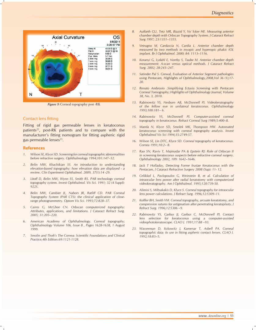
Evaluation of patients post refractive surgery-• After RK, topography demonstrates corneal
flattening,greatest at the center and decreased at the periphery (Figure 4,5).
• Helps to identify the surgical effect,postoperative regression, decentered zones and treat central islands.
• To determine the refractive power change after surgery, induced cylindrical change, and the temporal change (healing effect) after PRK.
• Planning of astigmatism reducing incisions (LRI).
Cataract surgeryIOL power calculation in patients with previous refractive surgery- Corneal topography is utilized to determine the “simulated keratometry” by analyzing the refractive power of the central cornea19,20.
Post penetrating keratoplastyTo guide selective suture removal, decide the placement of arcuate incisions and compression sutures to reduce high astigmatism21.
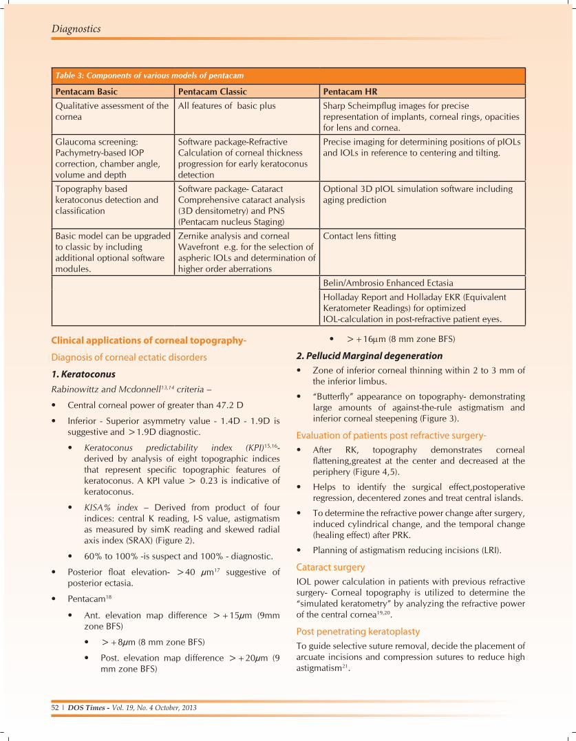
Table 3: Components of various models of pentacam
Pentacam Basic Pentacam Classic Pentacam HRQualitative assessment of the cornea
All features of basic plus Sharp Scheimpflug images for precise representation of implants, corneal rings, opacities for lens and cornea.
Glaucoma screening: Pachymetry-based IOP correction, chamber angle, volume and depth
Software package-Refractive Calculation of corneal thickness progression for early keratoconus detection
Precise imaging for determining positions of pIOLs and IOLs in reference to centering and tilting.
Topography based keratoconus detection and classification
Software package- Cataract Comprehensive cataract analysis (3D densitometry) and PNS (Pentacam nucleus Staging)
Optional 3D pIOL simulation software including aging prediction
Basic model can be upgraded to classic by including additional optional software modules.
Zernike analysis and corneal Wavefront e.g. for the selection of aspheric IOLs and determination of higher order aberrations
Contact lens fitting
Belin/Ambrosio Enhanced Ectasia
Holladay Report and Holladay EKR (Equivalent Keratometer Readings) for optimized IOL-calculation in post-refractive patient eyes.
www. dosonline.org l 53
Diagnostics
Contact lens fittingFitting of rigid gas permeable lenses in keratoconus patients22, post-RK patients and to compare with the manufacturer’s fitting nomogram for fitting aspheric rigid gas permeable lenses23.
References1. Wilson SE, Klyce SD. Screening for corneal topographic abnormalities
before refractive surgery. Ophthalmology 1994;101:147–52.
2. Belin MW, Khachikian SS. An introduction to understanding elevation-based topography: how elevation data are displayed - a review. Clin Experiment Ophthalmol. 2009, 37(1):14 -29.
3. Litoff D, Belin MW, Wynn SS, Smith RS. PAR technology corneal topography system. Invest Ophthalmol. Vis Sci. 1991; 32 (4 Suppl): 922S.
4. Belin MW, Cambier JL, Nabors JR, Ratliff CD. PAR Corneal Topography System (PAR CTS): the clinical application of close-range photogrammetry. Optom Vis Sci. 1995;72:828–37.
5. Cairns G, McGhee CN. Orbscan computerized topography: Attributes, applications, and limitations. J Cataract Refract Surg. 2005; 31:205–220.
6. American Academy of Ophthalmology. Corneal topography; Ophthalmology Volume 106, Issue 8 , Pages 1628-1638, 1 August 1999.
7. SmolinandThoft’sTheCornea:ScientificFoundationsandClinicalPractice,4th Edition.69:1121-1128.
Figure 5: Corneal topography post -RK
8. Auffarth GU, Tetz MR, Biazid Y, Vo¨lcker HE. Measuring anterior chamber depth with Orbscan Topography System. J Cataract Refract Surg 1997; 23:1351–1355.
9. Vetrugno M, Cardascia N, Cardia L. Anterior chamber depth measured by two methods in myopic and hyperopic phakic IOL implant. Br J Ophthalmol. 2000; 84: 1113–1116.
10. Koranyi G, Lydahl E, Norrby S, Taube M. Anterior chamber depth measurement: A-scan versus optical methods. J Cataract Refract Surg. 2002; 28:243–247.
11. Satinder Pal S. Grewal, Evaluation of Anterior Segment pathologies using Pentacam, Highlights of Ophthalmology,2008,Vol 36 (1);17- 20.
12. Renato Ambrosio .Simplifying Ectasia Screening with Pentacam Corneal Tomography; Highlights of Ophthalmology Journal, Volume 38, No. 3, 2010.
13. Rabinowitz YS, Nesburn AB, McDonnell PJ. Videokeratography of the fellow eye in unilateral keratoconus. Ophthalmology 1993;100:181– 6.
14. Rabinowitz YS, McDonnell PJ. Computer-assisted corneal topography in keratoconus. Refract Corneal Surg 1989;5:400–8.
15. Maeda N, Klyce SD, Smolek MK, Thompson HW. Automated keratoconus screening with corneal topography analysis. Invest Ophthalmol Vis Sci 1994;35:2749-57.
16. Wilson SE, Lin DTC, Klyce SD. Corneal topography of keratoconus. Cornea 1991;10:2– 8.
17. Rao SN, Raviv T, Majmudar PA & Epstein RJ: Role of Orbscan II in screening keratoconus suspects before refractive corneal surgery.Ophthalmology 2002, 109: 1642–1646.
18. Jack T Holladay, Detecting Forme frustae Keratoconus with the Pentacam, J Cataract Refractive Surgery 2008 (Sup): 11- 12.
19. Celikkol L, Pavlopoulos G, Weinstein B, et al. Calculation of intraocular lens power after radial keratotomy with computerized videokeratography. Am J Ophthalmol. 1995;120:739-50.
20. Alimisi S, Miltsakakis D, Klyce S. Corneal topography for intraocular lens power calculations. J Refract Surg. 1996;12:S309–11.
21. KofflerBH,SmithVM.Cornealtopography,arcuatekeratotomy,andcompression sutures for astigmatism after penetrating keratoplasty. J Refract Surg. 1996;12:S306 –9.
22. Rabinowitz YS, Garbus JJ, Garbus C, McDonnell PJ. Contact lens selection for keratoconus using a computer-assisted videophotokeratoscope. CLAO J. 1991;17:88 –93.
23. Wasserman D, Itzkowitz J, Kamenar T, Asbell PA. Corneal topographicdata:itsuseinfittingasphericcontactlenses.CLAOJ.1992;18:83–5.