Embed Size (px)
Citation preview
62 POLISH MARITIME RESEARCH, No 1/2010
INTRODUCTION
Multi-cylinder combustion engine in operation generates vibrations which directly and detrimentally impact lifetime of engine’s parts and the whole propulsion system.
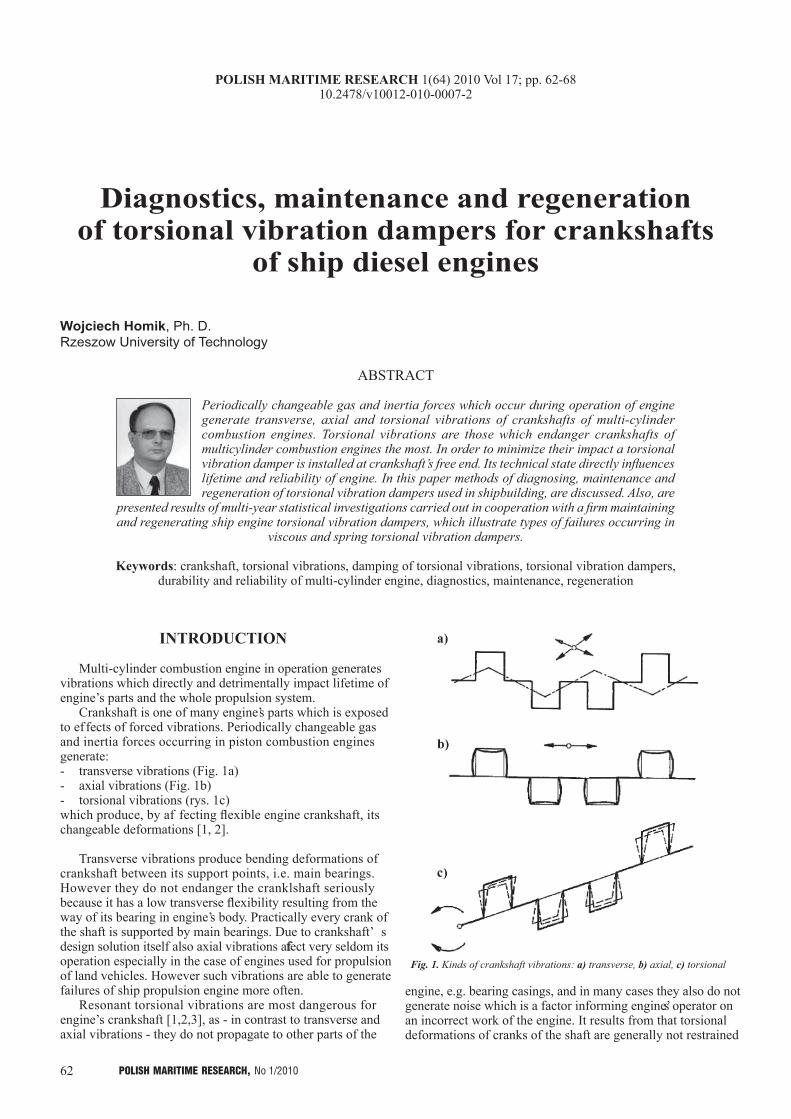
Crankshaft is one of many engine’s parts which is exposed to ef fects of forced vibrations. Periodically changeable gas and inertia forces occurring in piston combustion engines generate:- transverse vibrations (Fig. 1a)- axial vibrations (Fig. 1b)- torsional vibrations (rys. 1c)which produce, by af fecting flexible engine crankshaft, its changeable deformations [1, 2].
Transverse vibrations produce bending deformations of crankshaft between its support points, i.e. main bearings. However they do not endanger the cranklshaft seriously because it has a low transverse flexibility resulting from the way of its bearing in engine’s body. Practically every crank of the shaft is supported by main bearings. Due to crankshaft’ s design solution itself also axial vibrations affect very seldom its operation especially in the case of engines used for propulsion of land vehicles. However such vibrations are able to generate failures of ship propulsion engine more often.
Resonant torsional vibrations are most dangerous for engine’s crankshaft [1,2,3], as - in contrast to transverse and axial vibrations - they do not propagate to other parts of the
Diagnostics, maintenance and regeneration of torsional vibration dampers for crankshafts
of ship diesel engines
Wojciech Homik, Ph. D.Rzeszow University of Technology
ABSTRACT
Periodically changeable gas and inertia forces which occur during operation of engine generate transverse, axial and torsional vibrations of crankshafts of multi-cylinder combustion engines. Torsional vibrations are those which endanger crankshafts of multicylinder combustion engines the most. In order to minimize their impact a torsional vibration damper is installed at crankshaft’s free end. Its technical state directly influences lifetime and reliability of engine. In this paper methods of diagnosing, maintenance and regeneration of torsional vibration dampers used in shipbuilding, are discussed. Also, are
presented results of multi-year statistical investigations carried out in cooperation with a firm maintaining and regenerating ship engine torsional vibration dampers, which illustrate types of failures occurring in
viscous and spring torsional vibration dampers.
Keywords: crankshaft, torsional vibrations, damping of torsional vibrations, torsional vibration dampers, durability and reliability of multi-cylinder engine, diagnostics, maintenance, regeneration
Fig. 1. Kinds of crankshaft vibrations: a) transverse, b) axial, c) torsional
engine, e.g. bearing casings, and in many cases they also do not generate noise which is a factor informing engine’s operator on an incorrect work of the engine. It results from that torsional deformations of cranks of the shaft are generally not restrained
POLISH MARITIME RESEARCH 1(64) 2010 Vol 17; pp. 62-6810.2478/v10012-010-0007-2
63POLISH MARITIME RESEARCH, No 1/2010
by any factor except its rigidity hence torsional vibration amplitude can exceed allowable limits leading to twist damage of the crankshaft.
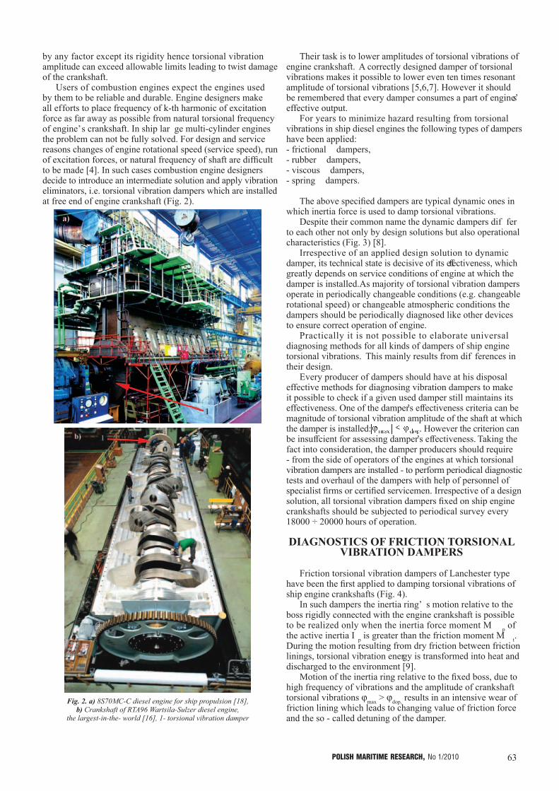
Users of combustion engines expect the engines used by them to be reliable and durable. Engine designers make all efforts to place frequency of k-th harmonic of excitation force as far away as possible from natural torsional frequency of engine’s crankshaft. In ship lar ge multi-cylinder engines the problem can not be fully solved. For design and service reasons changes of engine rotational speed (service speed), run of excitation forces, or natural frequency of shaft are difficult to be made [4]. In such cases combustion engine designers decide to introduce an intermediate solution and apply vibration eliminators, i.e. torsional vibration dampers which are installed at free end of engine crankshaft (Fig. 2).
Their task is to lower amplitudes of torsional vibrations of engine crankshaft. A correctly designed damper of torsional vibrations makes it possible to lower even ten times resonant amplitude of torsional vibrations [5,6,7]. However it should be remembered that every damper consumes a part of engine’s effective output.
For years to minimize hazard resulting from torsional vibrations in ship diesel engines the following types of dampers have been applied: - frictional dampers,- rubber dampers,- viscous dampers,- spring dampers.
The above specified dampers are typical dynamic ones in which inertia force is used to damp torsional vibrations.
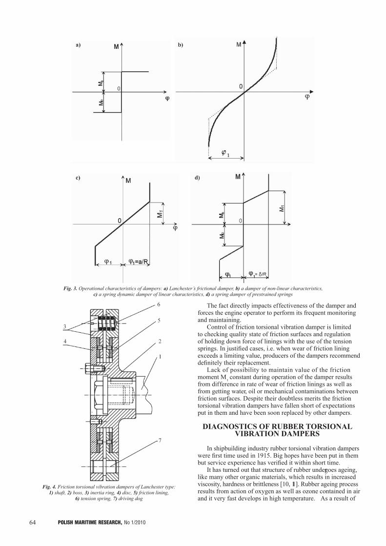
Despite their common name the dynamic dampers dif fer to each other not only by design solutions but also operational characteristics (Fig. 3) [8].
Irrespective of an applied design solution to dynamic damper, its technical state is decisive of its effectiveness, which greatly depends on service conditions of engine at which the damper is installed. As majority of torsional vibration dampers operate in periodically changeable conditions (e.g. changeable rotational speed) or changeable atmospheric conditions the dampers should be periodically diagnosed like other devices to ensure correct operation of engine.
Practically it is not possible to elaborate universal diagnosing methods for all kinds of dampers of ship engine torsional vibrations. This mainly results from dif ferences in their design.
Every producer of dampers should have at his disposal effective methods for diagnosing vibration dampers to make it possible to check if a given used damper still maintains its effectiveness. One of the damper’s effectiveness criteria can be magnitude of torsional vibration amplitude of the shaft at which the damper is installed: . However the criterion can be insuffcient for assessing damper’s effectiveness. Taking the fact into consideration, the damper producers should require - from the side of operators of the engines at which torsional vibration dampers are installed - to perform periodical diagnostic tests and overhaul of the dampers with help of personnel of specialist firms or certified servicemen. Irrespective of a design solution, all torsional vibration dampers fixed on ship engine crankshafts should be subjected to periodical survey every 18000 ÷ 20000 hours of operation.
DIAGNOSTICS OF FRICTION TORSIONAL VIBRATION DAMPERS
Friction torsional vibration dampers of Lanchester type have been the first applied to damping torsional vibrations of ship engine crankshafts (Fig. 4).
In such dampers the inertia ring’ s motion relative to the boss rigidly connected with the engine crankshaft is possible to be realized only when the inertia force moment M p of the active inertia I p is greater than the friction moment M t. During the motion resulting from dry friction between friction linings, torsional vibration energy is transformed into heat and discharged to the environment [9].
Motion of the inertia ring relative to the fixed boss, due to high frequency of vibrations and the amplitude of crankshaft torsional vibrations ϕmax > ϕdop, results in an intensive wear of friction lining which leads to changing value of friction force and the so - called detuning of the damper.
Fig. 2. a) 8S70MC-C diesel engine for ship propulsion [18], b) Crankshaft of RTA96 Wartsila-Sulzer diesel engine,
the largest-in-the- world [16], 1- torsional vibration damper
64 POLISH MARITIME RESEARCH, No 1/2010
The fact directly impacts effectiveness of the damper and forces the engine operator to perform its frequent monitoring and maintaining.
Control of friction torsional vibration damper is limited to checking quality state of friction surfaces and regulation of holding down force of linings with the use of the tension springs. In justified cases, i.e. when wear of friction lining exceeds a limiting value, producers of the dampers recommend definitely their replacement.
Lack of possibility to maintain value of the friction moment M t constant during operation of the damper results from difference in rate of wear of friction linings as well as from getting water, oil or mechanical contaminations between friction surfaces. Despite their doubtless merits the friction torsional vibration dampers have fallen short of expectations put in them and have been soon replaced by other dampers.
DIAGNOSTICS OF RUBBER TORSIONAL VIBRATION DAMPERS
In shipbuilding industry rubber torsional vibration dampers were first time used in 1915. Big hopes have been put in them but service experience has verified it within short time.
It has turned out that structure of rubber undergoes ageing, like many other organic materials, which results in increased viscosity, hardness or brittleness [10, 11]. Rubber ageing process results from action of oxygen as well as ozone contained in air and it very fast develops in high temperature. As a result of
Fig. 3. Operational characteristics of dampers: a) Lanchester’s frictional damper, b) a damper of non-linear characteristics, c) a spring dynamic damper of linear characteristics, d) a spring damper of prestrained springs
Fig. 4. Friction torsional vibration dampers of Lanchester type: 1) shaft, 2) boss, 3) inertia ring, 4) disc, 5) friction lining,
6) tension spring, 7) driving dog
65POLISH MARITIME RESEARCH, No 1/2010
ageing rather lar ge decrease of rubber strength properties as well as significant drop of its resistance to periodically changing loads takes place.
Lack of stable physical properties of rubber, connected with the above described phenomena, has not provided the rubber torsional vibration dampers with a greater role in shipbuilding industry. At the end of the 1950s application of rubber dampers was practically terminated. In spite of that they have been still in use on some older floating units.
Their short lifetime does not up to now prevent designers of car engines from their successful application. It mainly results from that car engine’s lifetime is much lower than that of ship engine and is equal at the most to about 2000000 km (trucks, buses). As results from tractional tests of car combustion engines fitted with rubber torsional vibration dampers their operational ef fectiveness drops after about 180000 km of mileage.
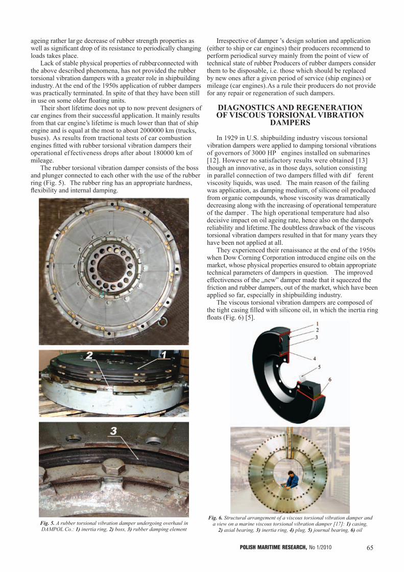
The rubber torsional vibration damper consists of the boss and plunger connected to each other with the use of the rubber ring (Fig. 5). The rubber ring has an appropriate hardness, flexibility and internal damping.
Irrespective of damper ’s design solution and application (either to ship or car engines) their producers recommend to perform periodical survey mainly from the point of view of technical state of rubber. Producers of rubber dampers consider them to be disposable, i.e. those which should be replaced by new ones after a given period of service (ship engines) or mileage (car engines). As a rule their producers do not provide for any repair or regeneration of such dampers.
DIAGNOSTICS AND REGENERATION OF VISCOUS TORSIONAL VIBRATION
DAMPERS
In 1929 in U.S. shipbuilding industry viscous torsional vibration dampers were applied to damping torsional vibrations of governors of 3000 HP engines installed on submarines [12]. However no satisfactory results were obtained [13] though an innovative, as in those days, solution consisting in parallel connection of two dampers filled with dif ferent viscosity liquids, was used. The main reason of the failing was application, as damping medium, of silicone oil produced from organic compounds, whose viscosity was dramatically decreasing along with the increasing of operational temperature of the damper . The high operational temperature had also decisive impact on oil ageing rate, hence also on the damper’s reliability and lifetime. The doubtless drawback of the viscous torsional vibration dampers resulted in that for many years they have been not applied at all.
They experienced their renaissance at the end of the 1950s when Dow Corning Corporation introduced engine oils on the market, whose physical properties ensured to obtain appropriate technical parameters of dampers in question. The improved effectiveness of the „new” damper made that it squeezed the friction and rubber dampers, out of the market, which have been applied so far, especially in shipbuilding industry.
The viscous torsional vibration dampers are composed of the tight casing filled with silicone oil, in which the inertia ring floats (Fig. 6) [5].
Fig. 5. A rubber torsional vibration damper undergoing overhaul in DAMPOL Co.: 1) inertia ring, 2) boss, 3) rubber damping element
Fig. 6. Structural arrangement of a viscous torsional vibration damper and a view on a marine viscous torsional vibration damper [17]: 1) casing,
2) axial bearing, 3) inertia ring, 4) plug, 5) journal bearing, 6) oil
66 POLISH MARITIME RESEARCH, No 1/2010
Diagnostics of such dampers depends on their design solutions. In present two design solutions are applied in industry: non-dismountable dampers (in car industry) and dismountable dampers (in shipbuilding industry).
Diagnostics of viscous torsional vibration dampers consists first of all in checking the vibration amplitude criterion and then measuring value of damping liquid viscosity [13].
Testing samples of the liquid (oil) should be taken from the damper being in neutral environment in order not to cause connection of oxygen and hydrogen atoms and tearing this way particle bonds and lowering real viscosity of the oil [14]. In the case of stating an inappropriate viscosity of the tested oil its replacement is recommended after very accurate cleansing all parts of the damper.
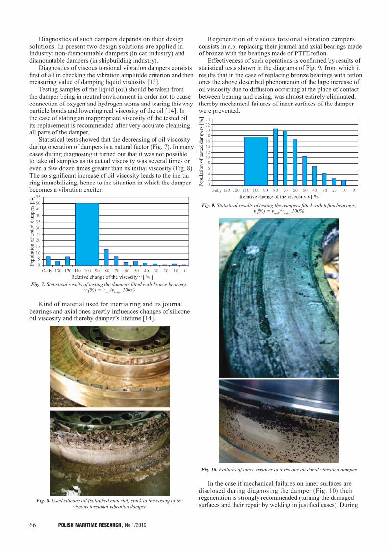
Statistical tests showed that the decreasing of oil viscosity during operation of dampers is a natural factor (Fig. 7). In many cases during diagnosing it turned out that it was not possible to take oil samples as its actual viscosity was several times or even a few dozen times greater than its initial viscosity (Fig. 8). The so significant increase of oil viscosity leads to the inertia ring immobilizing, hence to the situation in which the damper becomes a vibration exciter.
Fig. 7. Statistical results of testing the dampers fitted with bronze bearings, ν [%] = νreal /νinitial 100%
Kind of material used for inertia ring and its journal bearings and axial ones greatly influences changes of silicone oil viscosity and thereby damper’s lifetime [14].
Fig. 8. Used silicone oil (solidified material) stuck to the casing of the viscous torsional vibration damper
Regeneration of viscous torsional vibration dampers consists in a.o. replacing their journal and axial bearings made of bronze with the bearings made of PTFE teflon.
Effectiveness of such operations is confirmed by results of statistical tests shown in the diagrams of Fig. 9, from which it results that in the case of replacing bronze bearings with teflon ones the above described phenomenon of the large increase of oil viscosity due to diffusion occurring at the place of contact between bearing and casing, was almost entirely eliminated, thereby mechanical failures of inner surfaces of the damper were prevented.
Fig. 9. Statistical results of testing the dampers fitted with teflon bearings, ν [%] = νreal /νinitial 100%
Fig. 10. Failures of inner surfaces of a viscous torsional vibration damper
In the case if mechanical failures on inner surfaces are disclosed during diagnosing the damper (Fig. 10) their regeneration is strongly recommended (turning the damaged surfaces and their repair by welding in justified cases). During
67POLISH MARITIME RESEARCH, No 1/2010
regeneration of inner surfaces of a damper , changes of their geometrical parameters occur thereby also changes take place of dynamic properties of the damper. In such cases the damper should be filled with a liquid of a greater viscosity than that initial in order to restore appropriate effectiveness of the damper.
Tightness of the damper consitutes a factor of great influence on its correct operation. During overhaul of the damper its sealing is replaced and after its closing and filling its tightness test is performed.
Also, non-dismountable viscous torsional vibration dampers, like the above described rubber dampers, are not subjected to repair and regeneration and considered by their producers to be disposable parts.
DIAGNOSTICS AND REGENERATION OF SPRING TORSIONAL VIBRATION
DAMPERS
Research on a spring torsional vibration damper was initiated in 1958 when it turned out that viscous vibration dampers did not effectively lower crankshaft torsional vibrations in power system engines. The first spring damper was manufactured by Geislinger firm and installed on the Danish ferry „Holger Danske” in 1962. The spring torsional vibration damper, like rubber one, is composed of a boss and inertia ring mutually connected with the use of flexible elements in the form of spiral springs, packets of flexible pads and bush springs.
Today such dampers can be commonly found in ship propulsion engines as well as large power plants.
Two types of spring dampers are presently produced for shipbuilding industry: - Bush spring damper acc. Pielstick design (Fig. 11)- Damper with packets of straight springs (radial springs)
acc. Geislinger design (Fig. 12).
As compared with viscous trosional vibration dampers the spring dampers are characteristic of: - smaller dimensions,- small inertia moment of inertia ring relative to mass inertia
moment of boss,- greater resistance to mechanical failures,- greater lifetime,- higher allowable temperature of operation.
Spring dampers should be serviced once a year at least and their overhaul should be performed after about 20000 h of operation. Apart from checking the basic ef fectiveness criterion (amplitude criterion) of such damper its overhaul consists mainly in:- control of its tightness (after about 2000 h of operation),- control of patency of lubricating channels through which
oil is delivered between cooperating surfaces of boss and inertia ring,
- examination of technical state of flexible elements (springs, packets of springs) from the point of view of possible mechanical failures,
- control of technical state of bronze intermediate sliding pads.
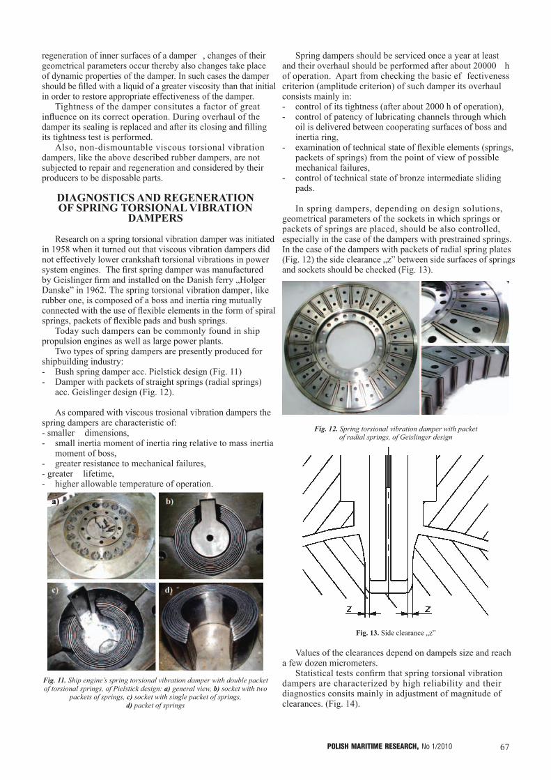
In spring dampers, depending on design solutions, geometrical parameters of the sockets in which springs or packets of springs are placed, should be also controlled, especially in the case of the dampers with prestrained springs. In the case of the dampers with packets of radial spring plates (Fig. 12) the side clearance „z” between side surfaces of springs and sockets should be checked (Fig. 13).
Fig. 12. Spring torsional vibration damper with packet of radial springs, of Geislinger design
Fig. 13. Side clearance „z”
Values of the clearances depend on damper’s size and reach a few dozen micrometers.
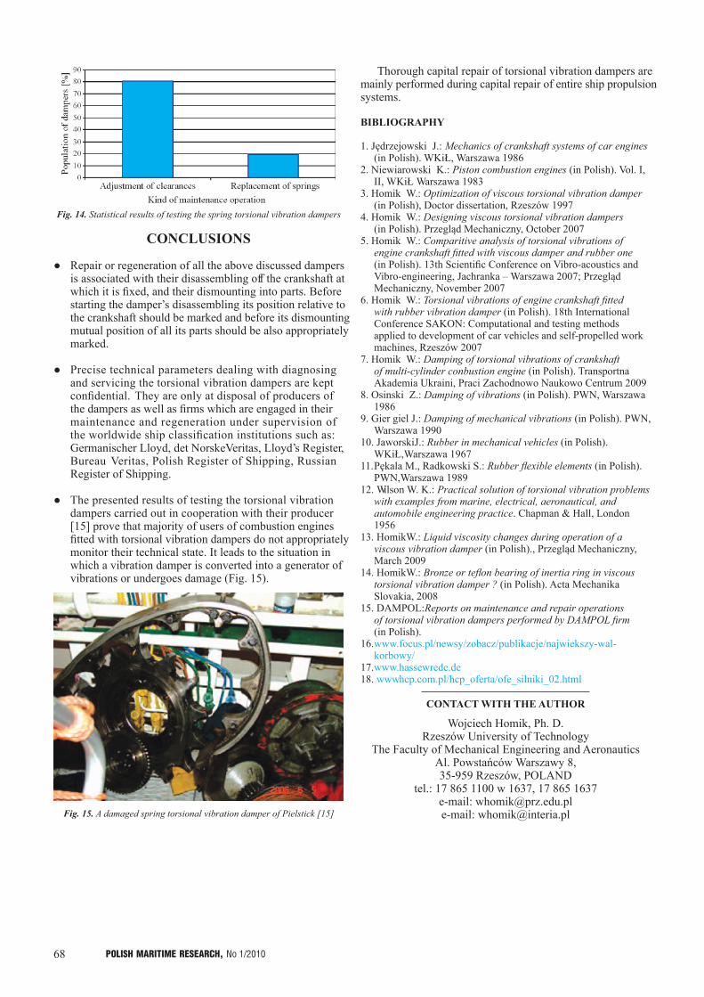
Statistical tests confirm that spring torsional vibration dampers are characterized by high reliability and their diagnostics consits mainly in adjustment of magnitude of clearances. (Fig. 14).
Fig. 11. Ship engine’s spring torsional vibration damper with double packet of torsional springs, of Pielstick design: a) general view, b) socket with two
packets of springs, c) socket with single packet of springs, d) packet of springs
68 POLISH MARITIME RESEARCH, No 1/2010
CONCLUSIONS
● Repair or regeneration of all the above discussed dampers is associated with their disassembling off the crankshaft at which it is fixed, and their dismounting into parts. Before starting the damper’s disassembling its position relative to the crankshaft should be marked and before its dismounting mutual position of all its parts should be also appropriately marked.
● Precise technical parameters dealing with diagnosing and servicing the torsional vibration dampers are kept confidential. They are only at disposal of producers of the dampers as well as firms which are engaged in their maintenance and regeneration under supervision of the worldwide ship classification institutions such as: Germanischer Lloyd, det Norske Veritas, Lloyd’s Register, Bureau Veritas, Polish Register of Shipping, Russian Register of Shipping.
● The presented results of testing the torsional vibration dampers carried out in cooperation with their producer [15] prove that majority of users of combustion engines fitted with torsional vibration dampers do not appropriately monitor their technical state. It leads to the situation in which a vibration damper is converted into a generator of vibrations or undergoes damage (Fig. 15).
Fig. 15. A damaged spring torsional vibration damper of Pielstick [15]
Fig. 14. Statistical results of testing the spring torsional vibration dampers
Thorough capital repair of torsional vibration dampers are mainly performed during capital repair of entire ship propulsion systems.
BIBLIOGRAPHY
1. Jędrzejowski J.: Mechanics of crankshaft systems of car engines (in Polish). WKiŁ, Warszawa 1986
2. Niewiarowski K.: Piston combustion engines (in Polish). Vol. I, II, WKiŁ Warszawa 1983
3. Homik W.: Optimization of viscous torsional vibration damper (in Polish), Doctor dissertation, Rzeszów 1997
4. Homik W.: Designing viscous torsional vibration dampers (in Polish). Przegląd Mechaniczny, October 2007
5. Homik W.: Comparitive analysis of torsional vibrations of engine crankshaft fitted with viscous damper and rubber one (in Polish). 13th Scientific Conference on Vibro-acoustics and Vibro-engineering, Jachranka – Warszawa 2007; Przegląd Mechaniczny, November 2007
6. Homik W.: Torsional vibrations of engine crankshaft fitted with rubber vibration damper (in Polish). 18th International Conference SAKON: Computational and testing methods applied to development of car vehicles and self-propelled work machines, Rzeszów 2007
7. Homik W.: Damping of torsional vibrations of crankshaft of multi-cylinder conbustion engine (in Polish). Transportna Akademia Ukraini, Praci Zachodnowo Naukowo Centrum 2009
8. Osinski Z.: Damping of vibrations (in Polish). PWN, Warszawa 1986
9. Gier giel J.: Damping of mechanical vibrations (in Polish). PWN, Warszawa 1990
10. Jaworski J.: Rubber in mechanical vehicles (in Polish). WKiŁ,Warszawa 1967
11. Pękala M., Radkowski S.: Rubber flexible elements (in Polish). PWN,Warszawa 1989
12. Wilson W. K.: Practical solution of torsional vibration problems with examples from marine, electrical, aeronautical, and automobile engineering practice. Chapman & Hall, London 1956
13. Homik W.: Liquid viscosity changes during operation of a viscous vibration damper (in Polish)., Przegląd Mechaniczny, March 2009
14. Homik W.: Bronze or teflon bearing of inertia ring in viscous torsional vibration damper ? (in Polish). Acta Mechanika Slovakia, 2008
15. DAMPOL: Reports on maintenance and repair operations of torsional vibration dampers performed by DAMPOL firm (in Polish).
16. www.focus.pl/newsy/zobacz/publikacje/najwiekszy-wal-korbowy/
17. www.hassewrede.de18. www.hcp.com.pl/hcp_oferta/ofe_silniki_02.html
CONTACT WITH THE AUTHOR
Wojciech Homik, Ph. D.Rzeszów University of Technology
The Faculty of Mechanical Engineering and AeronauticsAl. Powstańców Warszawy 8, 35-959 Rzeszów, POLAND
tel.: 17 865 1100 w 1637, 17 865 1637e-mail: [email protected]: [email protected]