Embed Size (px)
Citation preview
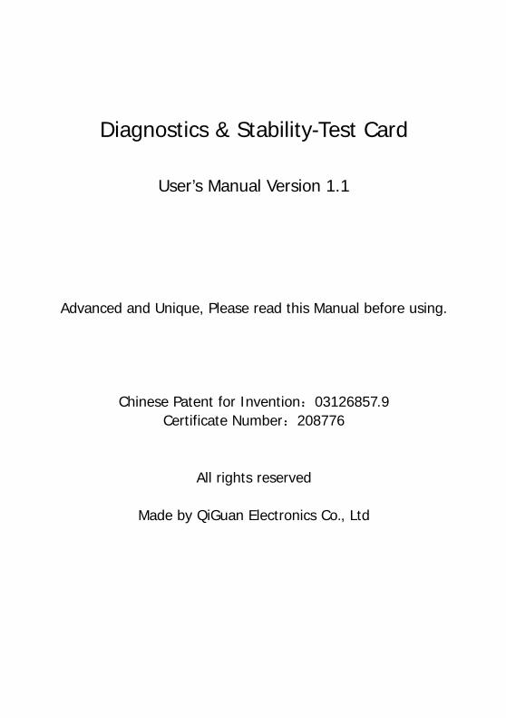
Diagnostics & Stability-Test Card
User’s Manual Version 1.1
Advanced and Unique, Please read this Manual before using.
Chinese Patent for Invention:03126857.9 Certificate Number:208776
All rights reserved
Made by QiGuan Electronics Co., Ltd

QiGuan Electronics Co., Ltd
1
Preface
Thanks for choosing Diagnostics & Stability-Test Card(DSTC) of QiGuan Electronics
Co., Ltd. If you have any question please visit our website www.pc-diagnosis.com for
detailed information, or send e-mail to [email protected]. We will give you answer as soon as
possible. Thanks for your trust and support!
DSTC of QiGuan Electronics Co., Ltd is kind of high performance product that can
troubleshoot failures and test the stability of computers. And it is simple and easy to use.
Using ultra-large-scale IC integrated module, DSTCs are really top quality products. They
are compact-structured, stable and reliable, and have more richer internal resources, more
excellent anti-jamming performance, and lower rate of self errors. All software are built-in,
the users do not need to install software. Combining advanced technology and user
behavioral science, the functional design is humanized to be convenient and user friendly.
QiGuan Electronics Co., Ltd is specialized in research, development and production
marketing of PC diagnostic cards, her main series of products like New Generation PC
Diagnostic Card, Kingnostic Card and DSTC are under the protection of national
patent(Patent NO., 03126857.9) and CE certified. All rights reserved. We do not produce
traditional products any more, all users please pay attention to the Logo “ 奇冠” and the
anti-counterfeit label. The specification and other information mentioned in this manual is
just for reference. Its real content will be updated regularly without further notice. For latest
product information please visit our website www.pc-diagnosis.com.
Welcome to visit the website of QiGuan Electronics Co., Ltd
http://www.pc-diagnosis.com
QiGuan Electronics Co., Ltd
2
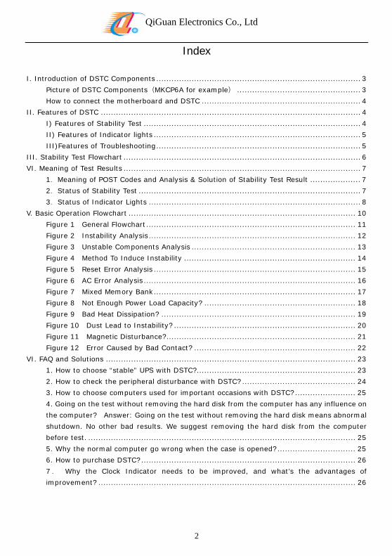
Index
I. Introduction of DSTC Components ................................................................................. 3
Picture of DSTC Components(MKCP6A for example) ................................................. 3
How to connect the motherboard and DSTC ............................................................... 4
II. Features of DSTC ....................................................................................................... 4
I) Features of Stability Test ...................................................................................... 4
II) Features of Indicator lights .................................................................................. 5
III)Features of Troubleshooting ................................................................................. 5
III. Stability Test Flowchart .............................................................................................. 6
VI. Meaning of Test Results .............................................................................................. 7
1.Meaning of POST Codes and Analysis & Solution of Stability Test Result .................... 7
2.Status of Stability Test ........................................................................................ 7
3.Status of Indicator Lights .................................................................................... 8
V. Basic Operation Flowchart .......................................................................................... 10
Figure 1 General Flowchart ................................................................................... 11
Figure 2 Instability Analysis .................................................................................. 12
Figure 3 Unstable Components Analysis ................................................................. 13
Figure 4 Method To Induce Instability .................................................................... 14
Figure 5 Reset Error Analysis ................................................................................ 15
Figure 6 AC Error Analysis .................................................................................... 16
Figure 7 Mixed Memory Bank ................................................................................ 17
Figure 8 Not Enough Power Load Capacity? ............................................................ 18
Figure 9 Bad Heat Dissipation? ............................................................................. 19
Figure 10 Dust Lead to Instability? ........................................................................ 20
Figure 11 Magnetic Disturbance? ........................................................................... 21
Figure 12 Error Caused by Bad Contact? ................................................................ 22
VI. FAQ and Solutions ................................................................................................... 23
1. How to choose “stable” UPS with DSTC? ............................................................... 23
2. How to check the peripheral disturbance with DSTC? ............................................. 24
3. How to choose computers used for important occasions with DSTC? ........................ 25
4. Going on the test without removing the hard disk from the computer has any influence on
the computer? Answer: Going on the test without removing the hard disk means abnormal
shutdown. No other bad results. We suggest removing the hard disk from the computer
before test. .......................................................................................................... 25
5. Why the normal computer go wrong when the case is opened? ............................... 25
6. How to purchase DSTC? ..................................................................................... 26
7. Why the Clock Indicator needs to be improved, and what’s the advantages of
improvement? ...................................................................................................... 26
QiGuan Electronics Co., Ltd
I. Introduction of DSTC Components
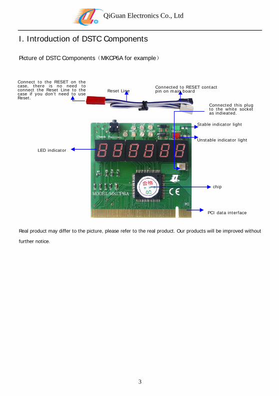
Picture of DSTC Components(MKCP6A for example)
3
Stable indicator light
Unstable indicator light
Connected to RESET contact pin on main board Reset Line
Connect to the RESET on the case, there is no need to connect the Reset Line to the case if you don’t need to use Reset.
Connected this plug to the white socket as indieated.
LED indicator
chip
PCI data interface
Real product may differ to the picture, please refer to the real product. Our products will be improved without
further notice.
QiGuan Electronics Co., Ltd
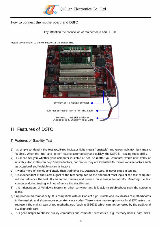
How to connect the motherboard and DSTC
Pay attention the connection of motherboard and DSTC!
Please pay attention to the connection of the RESET line.
connected to RESET contact
connect to RESET switch on the case
connect to RESET outlet on Diagnostics & Stability-Test Card
II. Features of DSTC
I) Features of Stability Test
1) It's simple to identify the test result-red indicator light means "unstable" and green indicator light means "stable". When the "red" and "green" flashes alternatively and quickly, the DSTC is testing the stability.
2) DSTC can tell you whether your computer is stable or not, no matter you computer works now stably or unstably. And it also can help find the factors, not matter they are invariable factors or variable factors such as occasional and invisible potential factors.
3) It works more efficiently and stably than traditional PC Diagnostic Card. It never stops in testing. 4) It is independent of the Reset Signal of the test computer, so the abnormal reset logic of the test computer
will not influence the test. It can correct failures and prevent pulse loss automatically. Resetting the test computer during testing will not influence the stability test.
5) It is independent of Windows System or other software, and it is able to troubleshoot even the screen is blank.
6) Unprecedented compatibility. It is compatible with all kinds of high, middle and low classes of motherboards in the market, and shows more accurate failure codes. There is even no exception for Intel 9XX series that represent the mainstream of top motherboards (such as SIS671) which can not be tested by the traditional PC diagnostic card.
7) It is good helper to choose quality computers and computer accessories, e.g. memory banks, hard disks,
4
QiGuan Electronics Co., Ltd
5
keyboards, and even the external equipments such as UPS, printers and computers used for ATM. And it also can help the sellers sell their computers by proving the stability.
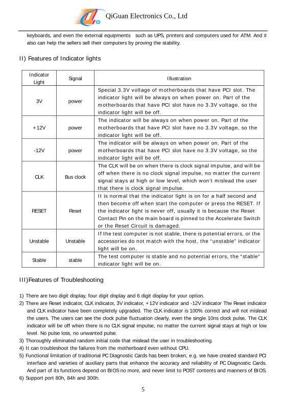
II) Features of Indicator lights
Indicator Light
Signal Illustration
3V power
Special 3.3V voltage of motherboards that have PCI slot. The indicator light will be always on when power on. Part of the motherboards that have PCI slot have no 3.3V voltage, so the indicator light will be off.
+12V power The indicator will be always on when power on. Part of the motherboards that have PCI slot have no 3.3V voltage, so the indicator light will be off.
-12V power The indicator will be always on when power on. Part of the motherboards that have PCI slot have no 3.3V voltage, so the indicator light will be off.
CLK Bus clock
The CLK will be on when there is clock signal impulse, and will be off when there is no clock signal impulse, no matter the current signal stays at high or low level, which won’t mislead the user that there is clock signal impulse.
RESET Reset
It is normal that the indicator light is on for a half second and then become off when start the computer or press the RESET. If the indicator light is never off, usually it is because the Reset Contact Pin on the main board is pinned to the Accelerate Switch or the Reset Circuit is damaged.
Unstable Unstable If the test computer is not stable, there is potential errors, or the accessories do not match with the host, the “unstable” indicator light will be on.
Stable stable The test computer is stable and no potential errors, the “stable” indicator light will be on.
III)Features of Troubleshooting
1) There are two digit display, four digit display and 6 digit display for your option. 2) There are Reset indicator, CLK indicator, 3V indicator, +12V indicator and -12V indicator The Reset indicator
and CLK indicator have been completely upgraded. The CLK indicator is 100% correct and will not mislead the users. The users can see the clock pulse fluctuation clearly, even the single 10ns clock pulse. The CLK indicator will be off when there is no CLK signal impulse, no matter the current signal stays at high or low level. No pulse loss, no unwanted pulse.
3) Thoroughly eliminated random initial code that mislead the user in troubleshooting. 4) It can troubleshoot the failures from the motherboard even without CPU. 5) Functional limitation of traditional PC Diagnostic Cards has been broken, e.g. we have created standard PCI
interface and varieties of auxiliary parts that enhance the accuracy and reliability of PC Diagnostic Cards. And part of its functions depend on BIOS no more, and never limit to POST contents and manners of BIOS.
6) Support port 80h, 84h and 300h.
QiGuan Electronics Co., Ltd
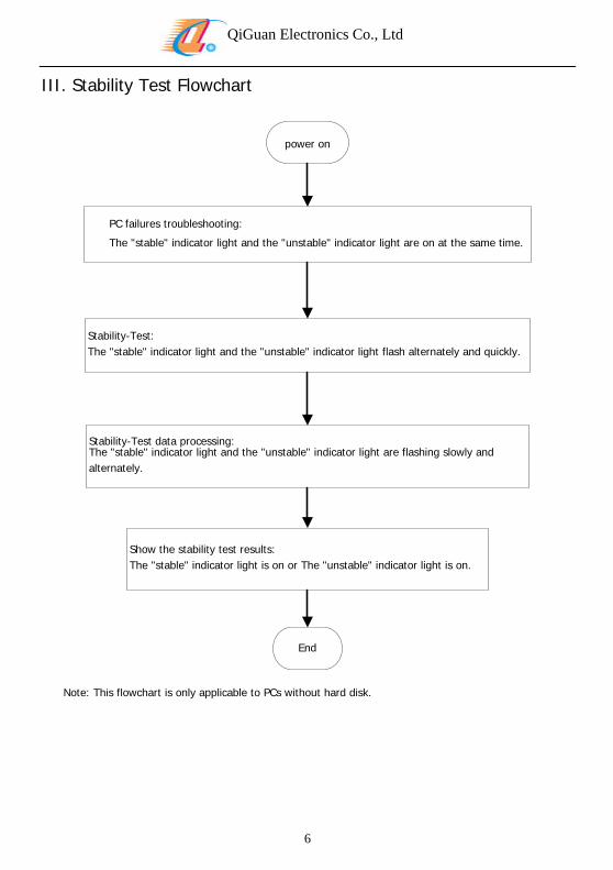
III. Stability Test Flowchart
power on
PC failures troubleshooting:
The "stable" indicator light and the "unstable" indicator light are on at the same time.
Stability-Test:The "stable" indicator light and the "unstable" indicator light flash alternately and quickly.
Stability-Test data processing:The "stable" indicator light and the "unstable" indicator light are flashing slowly and alternately.
Show the stability test results:The "stable" indicator light is on or The "unstable" indicator light is on.
End
Note: This flowchart is only applicable to PCs without hard disk.
6
QiGuan Electronics Co., Ltd
7
VI. Meaning of Test Results
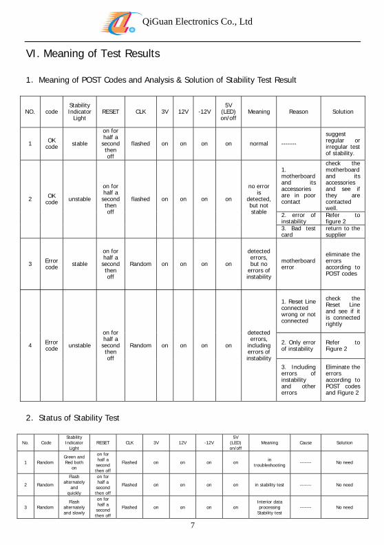
1.Meaning of POST Codes and Analysis & Solution of Stability Test Result
NO. code Stability Indicator
Light RESET CLK 3V 12V -12V
5V (LED) on/off
Meaning Reason Solution
1 OK code stable
on for half a
second then off
flashed on on on on normal -------
suggest regular or irregular test of stability.
2 OK code unstable
on for half a
second then off
flashed on on on on
no error is
detected, but not stable
1. motherboard and its accessories are in poor contact
check the motherboard and its accessories and see if they are contacted well.
2. error of instability
Refer to figure 2
3. Bad test card
return to the supplier
3 Error code stable
on for half a
second then off
Random on on on on
detected errors, but no
errors of instability
motherboard error
eliminate the errors according to POST codes
4 Error code unstable
on for half a
second then off
Random on on on on
detected errors,
including errors of instability
1. Reset Line connected wrong or not connected
check the Reset Line and see if it is connected rightly
2. Only error of instability
Refer to Figure 2
3. Including errors of instability and other errors
Eliminate the errors according to POST codes and Figure 2
2.Status of Stability Test
No. Code Stability Indicator
Light RESET CLK 3V 12V -12V
5V (LED) on/off
Meaning Cause Solution
1 Random Green and Red both
on
on for half a second then off
Flashed on on on on in troubleshooting ------- No need
2 Random
Flash alternately
and quickly
on for half a second then off
Flashed on on on on in stability test ------- No need
3 Random Flash
alternately and slowly
on for half a second then off
Flashed on on on on Interior data processing
Stability test ------- No need
QiGuan Electronics Co., Ltd
8
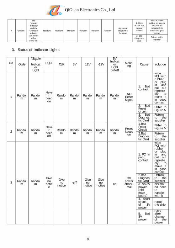
4 Random
the "stable" indicator and the
"unstable" indicator are never
off or never on.
Random Random Random Random Random RandomAbnormal diagnostic function
1. Dirty PCI or PCI
in poor contact
wipe PCI with rubber or plug in
and pull out repeatedly to
make it in good contact
2. Bad Diagnostic
card
Return to the supplier
3.Status of Indicator Lights
No. Code
”Stable”
Indicator
Light
RESET CLK 3V 12V -12V
5V Indicat
or Light on/off
Meaning Cause solution
1 Random
Random
Never
been on
Random
Random
Random
Random
Random
NO Reset Signal
1. Bad contact
wipe PCI with rubber or plug in and pull out repeatedly to make it in good contact
2. Bad Reset circuit
Refer to Figure 5
3. Bad Diagnostic Card
Return to the supplier
2 Random
Random
Never
been off
Random
Random
Random
Random
Random
Reset keeps
on
1.Bad Reset Circuit
Refer to Figure 5
2.Bad Diagnostic Card
Return to the supplier
3 Random
Random
Give no
notice
Give no
noticeoff
Give no
notice
Give no
notice
on
3V power abnor-
mal
1. PCI in poor contact
wipe PCI with rubber or plug in and pull out repeatedly to make it in good contact
2.Bad Diagnostic Card
Return to the supplier
3. No 3V power (old main board)
Normal, no need to handle with it
4. short circuit of 3V power
repair the chip
5. Bad 3V power
retry after change of the power
QiGuan Electronics Co., Ltd
9
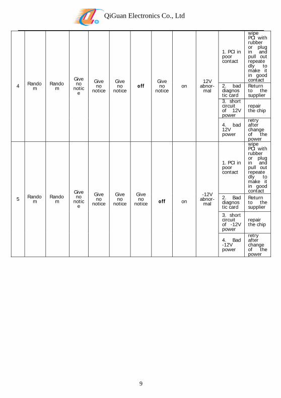
4 Random
Random
Give no
notice
Give no
notice
Give no
noticeoff
Give no
noticeon
12V abnor-
mal
1. PCI in poor contact
wipe PCI with rubber or plug in and pull out repeatedly to make it in good contact
2. bad diagnostic card
Return to the supplier
3. short circuit of 12V power
repair the chip
4. bad 12V power
retry after change of the power
5 Random
Random
Give no
notice
Give no
notice
Give no
notice
Give no
notice
off
on -12V
abnor-mal
1. PCI in poor contact
wipe PCI with rubber or plug in and pull out repeatedly to make it in good contact
2. Bad diagnostic card
Return to the supplier
3. short circuit of -12V power
repair the chip
4. Bad -12V power
retry after change of the power
QiGuan Electronics Co., Ltd
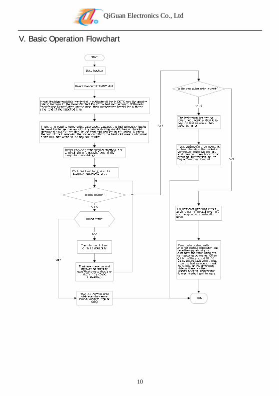
V. Basic Operation Flowchart
10
QiGuan Electronics Co., Ltd
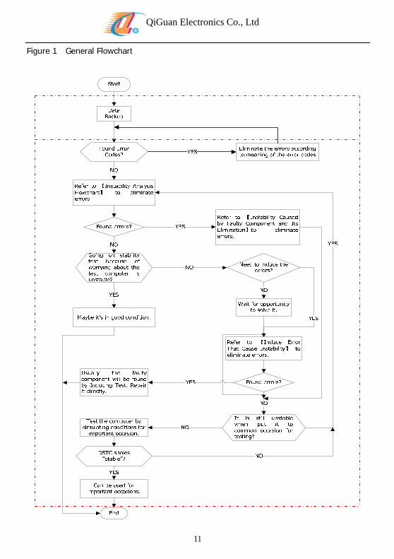
Figure 1 General Flowchart
11
QiGuan Electronics Co., Ltd
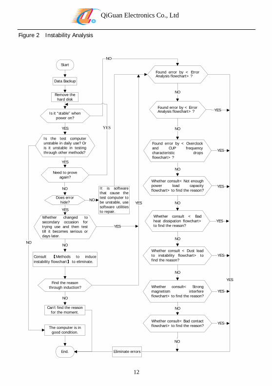
Figure 2 Instability Analysis
Start
Data Backup
Remove the hard disk
Is it “stable” when power on?
Is the test computer unstable in daily use? Or is it unstable in testing through other methods?
YES
Need to prove again?
YES
Does error hide?
NO
Whether changed to secondary occasion for trying use and then test till it becomes serious or days later.
YES
12
Consult 【Methods to induce instability flowchart】 to eliminate.
NO
Find the reason through induction?
Can’t find the reason for the moment.
NO
The computer is in good condition.
NO
It is software that cause the test computer to be unstable, use software utilities to repair.
NO
End.
Found error by < Error Analysis flowchart> ?
NO
YES
YES
Found error by < Error Analysis flowchart> ?
NO
YES
YES
Found error by < Overclock and CUP frequency characteristic drops flowchart> ?
YES
NO
Whether consult< Not enough power load capacity flowchart> to find the reason?
YES
NO
Whether consult < Bad heat dissipation flowchart> to find the reason?
YES
NO
Whether consult < Dust lead
NO
to instability flowchart> to find the reason?
YES
YES
NO
Whether consult< Strong magnetism interfere flowchart> to find the reason?
YES
NO
Whether consult< Bad contact flowchart> to find the reason?
YES
NO
Eliminate errors
QiGuan Electronics Co., Ltd
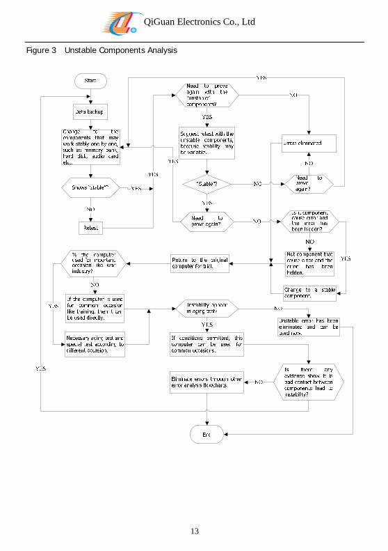
Figure 3 Unstable Components Analysis
13
QiGuan Electronics Co., Ltd
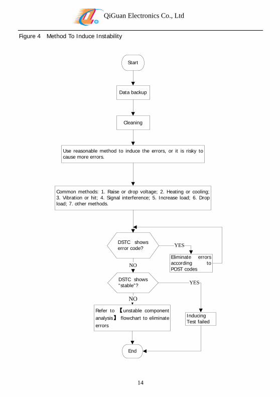
Figure 4 Method To Induce Instability
Start
Data backup
Cleaning
Use recause more e
asonable method to induce the errors, or it is risky to rrors.
Common3. Vibratload; 7.
methods: 1. Raise or drop voltage; 2. Heating or cooling; ion or hit; 4. Signal interference; 5. Increase load; 6. Drop other methods.
DSTC shows error code?
Eliminate errors according to POST codes
14
NO
DSTC shows “stable”?
Inducing Test failed
Refer to 【unstable component analysis】 flowchart to eliminate errors
YES
NO
End
YES
QiGuan Electronics Co., Ltd
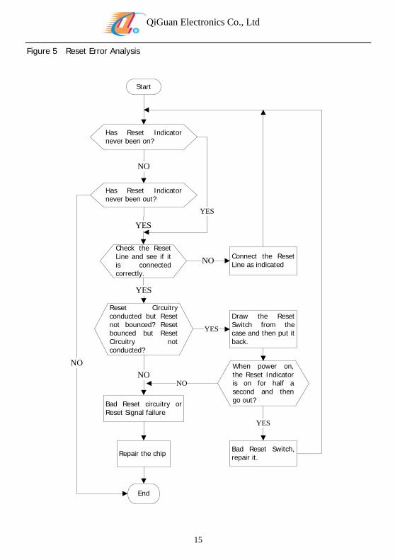
Figure 5 Reset Error Analysis
Start
Has Reset Indicator never been on?
Has Reset Indicator never been out?
Check the Reset Line and see if it is connected correctly.
YES
Reset Circuitry conducted but Reset not bounced? Reset bounced but Reset Circuitry not conducted?
YES
Connect the Reset Line as indicated
15
Bad Reset circuitry or Reset Signal failure
Repair the chip
End
NO
Bad Reset Switch, repair it.
NO
YES
NO
Draw the Reset Switch from the case and then put it back.
NO When power on, the Reset Indicator is on for half a second and then go out?
YES
YES
NO
QiGuan Electronics Co., Ltd
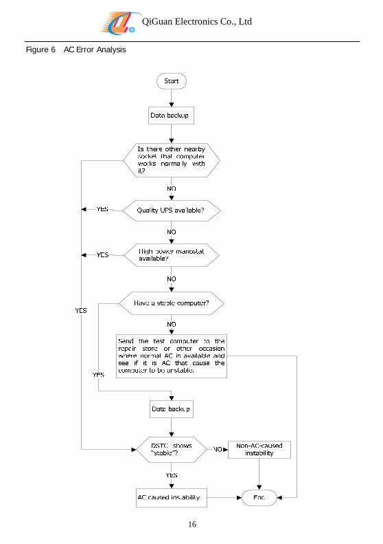
Figure 6 AC Error Analysis
16
QiGuan Electronics Co., Ltd
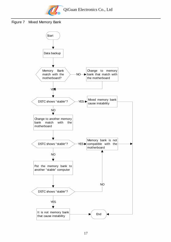
Figure 7 Mixed Memory Bank
Start
Data backup
Memory Bank match with the motherboard?
DSTC shows “stable”?
YES
Change to memory bank that match with the motherboard
NO
Change tbank matchmotherboa
17
o another memory with the
rd
Mixed memory bank cause instability
NO
YES
DSTC shows “stable”?Memory bank is not compatible with the motherboard
NO
YES
Put the memory bank to another “stable” computer
DSTC shows “stable”?
NO
YES
It is not memory bank that cause instability End
QiGuan Electronics Co., Ltd
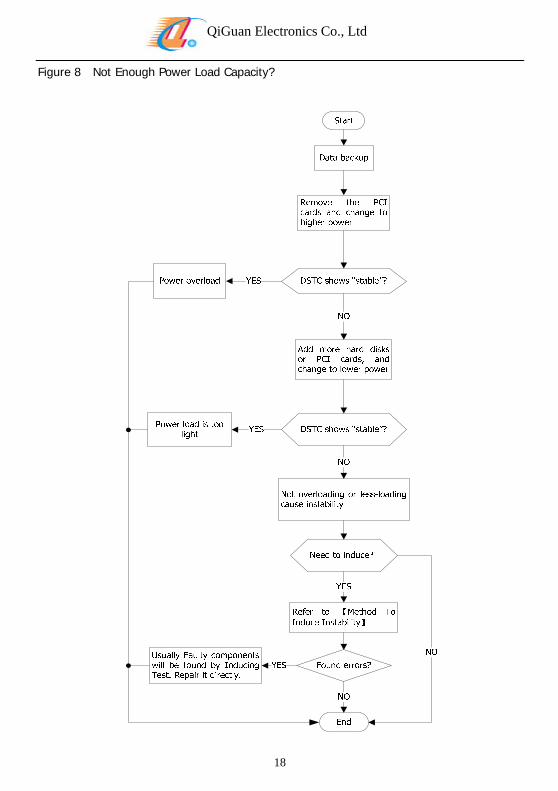
Figure 8 Not Enough Power Load Capacity?
18
QiGuan Electronics Co., Ltd
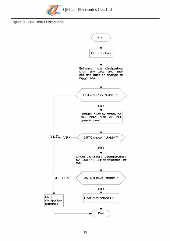
Figure 9 Bad Heat Dissipation?
19
QiGuan Electronics Co., Ltd
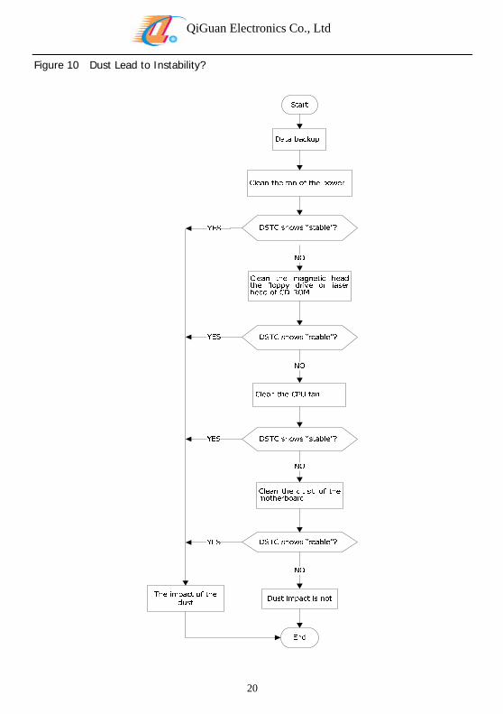
Figure 10 Dust Lead to Instability?
20
QiGuan Electronics Co., Ltd
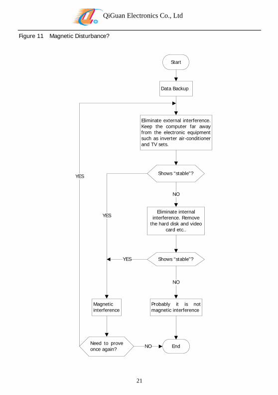
Figure 11 Magnetic Disturbance?
Start
Data Backup
Eliminate external interference. Keep the computer far away from the electronic equipment such as inverter air-conditioner and TV sets.
Shows “stable”?
Eliminate internal interference. Remove
the hard disk and video card etc..
21
Shows “stable”?
NO
NO
Probably it is not magnetic interference
Magnetic interference
EndNeed to prove once again? NO
YES
YES
YES
QiGuan Electronics Co., Ltd
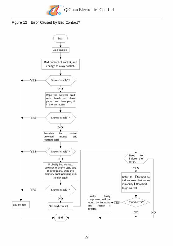
Figure 12 Error Caused by Bad Contact?
Start
Data backup
Bad contact of socket, and change to okay socket.
Shows “stable”?
Wipe the network card with brush or clean paper, and then plug it in the slot again
NO
Shows “stable”?
Probably bad contact between mouse and motherboard
NO
Shows “stable”?
22
Probably bad contact between memory band and
motherboard, wipe the memory bank and plug it in
the slot again
NO
Shows “stable”?
Non-bad-contact
NO
YES
YES
YESNeed to induce the error?
Bad contact
End
YES
Usually faulty component will be found by Inducing Test. Repair it directly.
YES
Refer to 【Method to induce error that cause instability】flowchart to go on test
Found error?YES
NO NO
QiGuan Electronics Co., Ltd
VI. FAQ and Solutions
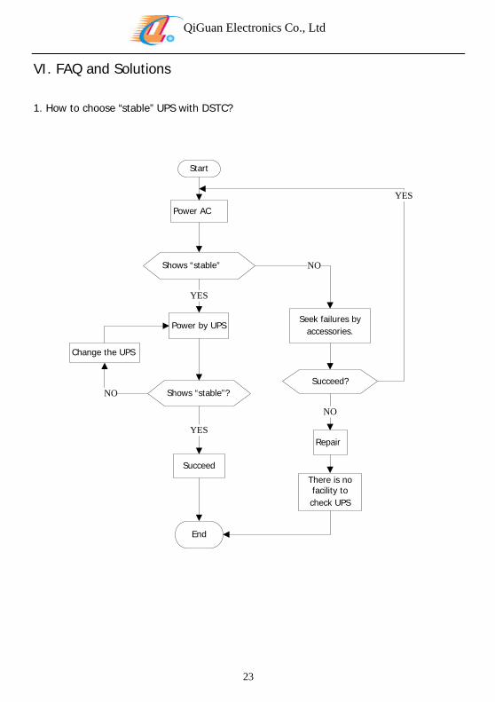
1. How to choose “stable” UPS with DSTC?
Power AC
Shows “stable”
Power by UPS
Succeed?
Seek failures by accessories.
Start
YES
NO
YES
Change the UPS
23
End
Shows “stable”?NO
Succeed
NO
YESRepair
There is no facility to check UPS
QiGuan Electronics Co., Ltd
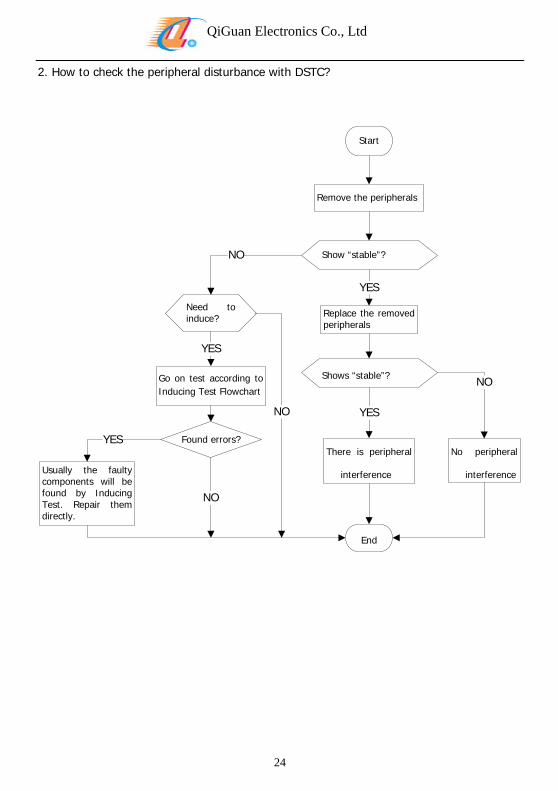
2. How to check the peripheral disturbance with DSTC?
Start
Remove the peripherals
Show “stable”?
Replace the removed peripherals
YES
Shows “stable”?
NO
Need to induce?
Go on test according to Inducing Test Flowchart
24
There is peripheral
interference
YES
End
Usually the faulty components will be found by Inducing Test. Repair them directly.
Found errors?YES
NO
YES
NO
No peripheral
interference
NO
QiGuan Electronics Co., Ltd
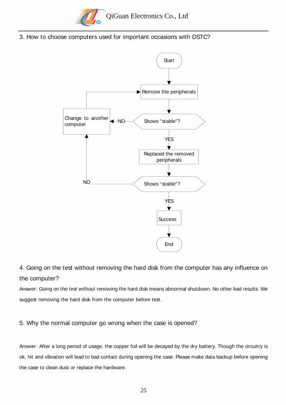
3. How to choose computers used for important occasions with DSTC?
Start
Remove the peripherals
Shows “stable”?
Replaced the removed peripherals
YES
Change tcomputer
o another NO
Shows “stable”?
25
YES
Success
End
NO
4. Going on the test without removing the hard disk from the computer has any influence on
the computer?
Answer: Going on the test without removing the hard disk means abnormal shutdown. No other bad results. We
suggest removing the hard disk from the computer before test.
5. Why the normal computer go wrong when the case is opened?
Answer: After a long period of usage, the copper foil will be decayed by the dry battery. Though the circuitry is
ok, hit and vibration will lead to bad contact during opening the case. Please make data backup before opening
the case to clean dust or replace the hardware.
QiGuan Electronics Co., Ltd
26
6. How to purchase DSTC?
Answer: If you are going to use it for repair, we suggest that you buy motherboards without components. If you
need to fix it on the host, you’d better buy the models with external LEDs fixed on the hob.
7. Why the Clock Indicator needs to be improved, and what’s the advantages of
improvement?
Answer: Clock signal of the PCI Bus is usually through the ways bellow.
1. Traditional motherboard use static Clock. There is always clock signal no matter if PCI slot is plugged with
expansion card or not, and the expansion card is working or not. Now most of the existing motherboards
use dynamic Clock. There is Clock Signal when it is working, and there is no Clock Signal when it is off.
2. Unlike data signal, control signal, and other Bus Signals, under general circumstances there will be Clock
Signal immediately when power on successfully, and it will keep on until the Reset Signal is out. Even if
you press the Reset and never loose it, the Clock Signal will bring out.
Some traditional diagnostic cards have two design defects.
1. Clock Signal is too fast to catch by naked eyes, which always mislead users that there is no Clock Signal.
2. When the Clock Signal is out, traditional Clock Indicator will be on no matter if it stays at high or low level,
which will mislead users that there is Clock Signal.
The Clock Signal of DSTC has been enhanced to be 100% accurate, and won’t mislead the users. The users
can see it clearly when the Clock Signal Pulse fluctuates, even if it is 10ns pulse(100 M, PCI Bus utmost 66 M).
When there is no Clock Signal, the Clock Indicator is off no matter if it stays at high or low level, which won’t
mislead the users. No loss of pulse, and no unneeded pulse.