Embed Size (px)
Citation preview
User’sManual Diaphragm Sealed
Differential Pressure andPressure TransmittersEJ118 and EJ438
IM 01C25H01-01E
IM 01C25H01-01E13th Edition
Toc-1
IM 01C25H01-01E
Diaphragm Sealed Differential Pressure andPressure TransmittersEJ118 and EJ438
IM 01C25H01-01E 13th Edition
13th Edition: Nov. 2019 (YK)All Rights Reserved, Copyright © 2004, Yokogawa Electric Corporation
Contents1. Introduction ............................................................................................... 1-1
Regarding This Manual ................................................................................................1-2 Trademarks ...................................................................................................................1-21.1 Safe Use of This Product .................................................................................1-31.2 Warranty .............................................................................................................1-5
2. Handling Cautions .................................................................................... 2-12.1 Model and Specifications Check .....................................................................2-12.2 Unpacking ..........................................................................................................2-12.3 Storage ...............................................................................................................2-12.4 Selecting the Installation Location ................................................................2-22.5 Pressure Connection ........................................................................................2-22.6 Waterproofing of Cable Conduit Connections ..............................................2-22.7 Restrictions on Use of Radio Transceivers ...................................................2-32.8 Insulation Resistance and Dielectric Strength Test ......................................2-32.9 Installation of an Explosion-Protected Instrument .......................................2-4
2.9.1 FM Approval .......................................................................................2-42.9.2 CSACertification ................................................................................2-62.9.3 ATEXCertification ..............................................................................2-82.9.4 IECExCertification ...........................................................................2-13
2.10 EMC Conformity Standards ...........................................................................2-152.11 Pressure Equipment Directive (PED) ...........................................................2-152.12 EU RoHS Directive ..........................................................................................2-162.13 Safety Requirement Standards .....................................................................2-16
3. Component Names .................................................................................. 3-14. Installation ................................................................................................. 4-1
4.1 Precautions .......................................................................................................4-14.2 Mounting the Diaphragm Seals .......................................................................4-14.3 Transmitter Mounting .......................................................................................4-24.4 Mounting the Flushing Connection Ring .......................................................4-4
4.4.1 Mounting to Pressure Detector Section ............................................. 4-44.4.2 Mounting to Process Flange ..............................................................4-4
Toc-2
IM 01C25H01-01E
4.5 Affixing the Teflon Film ....................................................................................4-54.6 Rotating Transmitter Section ...........................................................................4-54.7 Changing Integral Indicator Direction ............................................................4-6
5. Wiring ......................................................................................................... 5-15.1 Wiring Precautions ...........................................................................................5-15.2 Selecting the Wiring Materials .........................................................................5-15.3 Connections of External Wiring to Terminal Box ..........................................5-1
5.3.1 Power Supply Wiring Connection ......................................................5-25.3.2 External Indicator Connection............................................................5-25.3.3 Communicator Connection ................................................................5-25.3.4 Check Meter Connection ...................................................................5-35.3.5 Status Output Connection ..................................................................5-3
5.4 Wiring .................................................................................................................5-35.4.1 LoopConfiguration ............................................................................5-35.4.2 Wiring Installation ...............................................................................5-4
5.5 Grounding ..........................................................................................................5-55.6 Power Supply Voltage and Load Resistance .................................................5-5
6. Operation ................................................................................................... 6-16.1 Preparation for Starting Operation .................................................................6-16.2 Zero Point Adjustment .....................................................................................6-36.3 Starting Operation ............................................................................................6-46.4 Shutting Down Operation ................................................................................6-46.5 Venting or Draining Transmitter Process-Detector Section ........................6-5
6.5.1 Draining Condensate for Flushing Connection Ring ......................... 6-56.5.2 Venting Gas for Flushing Connection Ring ........................................ 6-5
6.6 Local Parameter Setting ...................................................................................6-66.6.1 Local Parameter Setting (LPS) Overview .......................................... 6-66.6.2 Activating Local Parameter Setting ...................................................6-86.6.3 Parameter Setting Review .................................................................6-86.6.4 LoopTestConfiguration .....................................................................6-96.6.5 TagNumberConfiguration .................................................................6-96.6.6 PressureUnitConfiguration...............................................................6-96.6.7 PressureLRV/URVConfiguration ...................................................6-106.6.8 DampingTimeConstantConfiguration ...........................................6-106.6.9 OutputModeConfiguration .............................................................6-106.6.10 DisplayOut1Configuration .............................................................6-106.6.11 Re-range by applying actual pressure (LRV/URV). ......................... 6-116.6.12 Device Information Display .............................................................. 6-116.6.13 Save or Cancel................................................................................. 6-11
Toc-3
IM 01C25H01-01E
6.6.14 AbortConfiguration ..........................................................................6-126.6.14.1 AbortConfiguration(Menu) ............................................6-126.6.14.2 AbortConfiguration(Parameter) ....................................6-12
6.6.15 Local Parameter Setting Lock ..........................................................6-126.6.16 Others ..............................................................................................6-12
7. Maintenance .............................................................................................. 7-17.1 Overview ............................................................................................................7-17.2 Calibration Instruments Selection ..................................................................7-17.3 Calibration .........................................................................................................7-17.4 Disassembly and Reassembly ........................................................................7-3
7.4.1 Replacing the Integral Indicator .........................................................7-37.4.2 Replacing the CPU Board Assembly ................................................. 7-4
7.5 Troubleshooting ................................................................................................7-47.5.1 Basic Troubleshooting .......................................................................7-57.5.2 Troubleshooting Flowcharts ...............................................................7-57.5.3 Alarms and Countermeasures ...........................................................7-7
8. General Specifications ............................................................................ 8-1Revision Information
When using the transmitters in a Safety Instrumented System application, refer to the Functional Safety Manual (Document No.: TI 01C25A05-01EN or TI 01C25A05-21EN for option code SLT) and follow the instructions and procedures described there.The document can be downloaded from the website of Yokogawa. (Website address: https://www.yokogawa.com/solutions/products-platforms/field-instruments/)In order to satisfy the requirement of Safety Instrumented System, executing parameters setting is required. Please refer to the clause of “Setting Parameters” for setting range in the following manuals for the actual operation.BRAIN: IM 01C25T03-01E HART: IM 01C25T01-06ENPlease also refer to the contact output setting in the same clause. After installingthetransmitter,confirmthattherangeandunitissetcorrectly.Calibration of the transmitters shall be done after completing the range setting.
<1. Introduction> 1-1
IM 01C25H01-01E
1. IntroductionThankyouforpurchasingtheDPharpDifferentialPressure and pressure transmitter.
Your Pressure Transmitter was precisely calibrated at the factory before shipment. To ensure both safetyandefficiency,pleasereadthismanualcarefully before you operate the instrument.
NOTEThis manual describes the hardware configurationsofthetransmitterslistedinbelow.Forinformationonthesoftwareconfigurationand operation, please refer to either IM 01C25T03-01E for the BRAIN communication type, or IM 01C25T01-06EN for the HART communication type.
For FOUNDATION Fieldbus protocol type, please refer to IM 01C25T02-01E. For PROFIBUS PA protocol type, please refer to IM 01C25T04-01EN.
Forthespecifications,externaldimensions,andmodel,suffixandoptioncodesofeachproduct,pleaserefertotheGeneralSpecificationssheetas listed in the Chapter 8.
Model Style codeEJX118A S2EJX438A S2EJA118E S1, S2 EJA438E S1, S2
To ensure correct use of this instrument, read both the hardware and software manuals thoroughly before use.
WARNING
When using the transmitters in a Safety Instrumented System application, refer to the Functional Safety Manual (Document No.: TI 01C25A05-01EN or TI 01C25A05-21EN for option code SLT) and follow the instructions and procedures described there.The document can be downloaded from the website of Yokogawa. (Website address: https://www.yokogawa.com/solutions/products-platforms/field-instruments/)In order to satisfy the requirement of Safety Instrumented System, executing parameters setting is required. Please refer to the clause of “Setting Parameters” for setting range in the following manuals for the actual operation.BRAIN: IM 01C25T03-01EHART: IM 01C25T01-06ENPlease also refer to the contact output setting in the same clause. After installing the transmitter, confirmthattherangeandunitissetcorrectly.Calibration of the transmitters shall be done after completing the range setting.
NOTEWhen describing the model name like EJ118 or EJ438, it shows the applicability for both EJX118A and EJA118E or EJX438A and EJA438E.
NOTEUnless otherwise stated, the illustrations in this manual are of the EJ118 diaphragm sealed differentialpressuretransmitter. Users of the EJ438 should bear in mind that certainfeaturesoftheirinstrumentwilldifferfromthose shown in the illustrations of the EJ118.
<1. Introduction> 1-2
IM 01C25H01-01E
Regarding This Manual• Thismanualandtheidentificationtagattached
on the packing box are essential parts of the product. Please keep them in a safe place for future reference.
• This manual should be provided to the end user.
• The contents of this manual are subject to change without prior notice.
• All rights reserved. No part of this manual may be reproduced in any form without Yokogawa’s written permission.
• Yokogawa makes no warranty of any kind with regard to this manual, including, but not limited to, implied warranty of merchantability and fitnessforaparticularpurpose.
• If any question arises or errors are found, or if any information is missing from this manual, please inform the nearest Yokogawa sales office.
• Thespecificationscoveredbythismanualarelimited to those for the standard type under the specifiedmodelnumberbreak-downanddonotcover custom-made instruments.
• Pleasenotethatchangesinthespecifications,construction, or component parts of the instrumentmaynotimmediatelybereflectedin this manual at the time of change, provided that postponement of revisions will not cause difficultytotheuserfromafunctionalorperformance standpoint.
• Yokogawa assumes no responsibilities for this product except as stated in the warranty.
• If the customer or any third party is harmed by the use of this product, Yokogawa assumes no responsibility for any such harm owing to any defects in the product which were not predictable, or for any indirect damages.
• The following safety symbols are used in this manual:
WARNING
Indicates a potentially hazardous situation which, if not avoided, could result in death or serious injury.
CAUTIONIndicates a potentially hazardous situation which, if not avoided, may result in minor or moderate injury. It may also be used to alert against unsafe practices.
IMPORTANTIndicates that operating the hardware or software in this manner may damage it or lead to system failure.
NOTEDraws attention to information essential for understanding the operation and features.
Direct current
Functional grounding terminal
CautionThis symbol indicates that the operator must refer to an explanation in the user’s manual in order to avoid the risk of injury or death of personnel or damage to the instrument.
Trademarks • ‘DPharp’, ‘EJX’, ‘EJA’, ‘FieldMate’ and ‘BRAIN
TERMINAL’ are registered trademarks of Yokogawa Electric Corporation. Company names and product names used in this material are registered trademarks or trademarks of their respective owners.
• In this manual, trademarks or registered trademarks are not marked with ™ or ®.
<1. Introduction> 1-3
IM 01C25H01-01E
1.1 Safe Use of This Product For the safety of the operator and to protect the instrument and the system, please be sure to follow this manual’s safety instructions when handling this instrument. If these instructions are not heeded, the protection provided by this instrument may be impaired. In this case, Yokogawa cannot guarantee that the instrument can be safely operated. Please pay special attention to the following points:
(a) Installation
WARNING
• This instrument may only be installed by an engineer or technician who has an expert knowledge of this device. Operators are not allowed to carry out installation unless they meet this condition.
• With high process temperatures, care must be taken not to burn yourself by touching the instrument or its casing.
• Never loosen the process connector nuts when the instrument is installed in a process. This can lead to a sudden, explosive release ofprocessfluids.
• When draining condensate from the pressure detector section, take appropriate precautions to prevent the inhalation of harmful vapors and the contact of toxic processfluidswiththeskinoreyes.
• When removing the instrument from a hazardous process, avoid contact with the fluidandtheinteriorofthemeter.
• All installation shall comply with local installation requirements and the local electrical code.
(b) Wiring
WARNING
• The instrument must be installed by an engineer or technician who has an expert knowledge of this instrument. Operators are not permitted to carry out wiring unless they meet this condition.
• Before connecting the power cables, please confirmthatthereisnocurrentflowingthrough the cables and that the power supply totheinstrumentisswitchedoff.
(c) Operation
WARNING
• Wait5min.afterpoweristurnedoff,beforeopening the covers.
• Do not open the cover in wet weather or humid environment. If the cover is opened, stated enclosure protection is not applicable.
(d) Maintenance
WARNING
• Please carry out only the maintenance procedures described in this manual. If you require further assistance, please contact the nearestYokogawaoffice.
• Care should be taken to prevent the build up of dust or other materials on the display glass and the name plate. To clean these surfaces, use a soft, dry cloth.
(e) Explosion Protected Type Instrument
WARNING
• Users of explosion proof instruments should referfirsttosection2.9(InstallationofanExplosion Protected Instrument) of this manual.
• The use of this instrument is restricted to those who have received appropriate training in the device.
• Take care not to create sparks when accessing the instrument or peripheral devices in a hazardous location.
(f) Modification
WARNING
• Yokogawa will not be liable for malfunctions ordamageresultingfromanymodificationmade to this instrument by the customer.
(g) Product Disposal
• The instrument should be disposed of in accordance with local and national legislation/ regulations.
<1. Introduction> 1-4
IM 01C25H01-01E
(h) Authorized Representative in EEA
• In relation to the CE Marking, The authorised representative for this product in the EEA (European Economic Area) is: Yokogawa Europe B.V. Euroweg 2, 3825 HD Amersfoort,The Netherlands
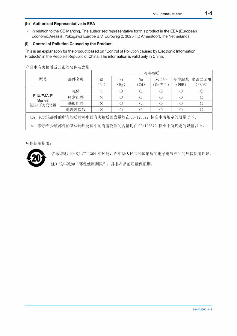
(i) Control of Pollution Caused by the Product
This is an explanation for the product based on “Control of Pollution caused by Electronic InformationProducts” in the People’s Republic of China. The information is valid only in China.
产品中有害物质或元素的名称及含量
型号 部件名称
有害物质
铅
(Pb)
汞
(Hg)
镉
(Cd)
六价铬
(Cr(VI))
多溴联苯
(PBB)
多溴二苯醚
(PBDE)
EJX/EJA-ESeries
差压/压力变送器
壳体 ×
膜盒组件 ×
基板组件 ×
电源连接线 ×
:表示该部件的所有均质材料中的有害物质的含量均在 GB/T26572 标准中所规定的限量以下。
×:表示至少该部件的某些均质材料中的有害物质的含量均在 GB/T26572 标准中所规定的限量以上。
环保使用期限:
该标识适用于 SJ /T11364 中所述,在中华人民共和国销售的电子电气产品的环保使用期限。
注)该年数为“环保使用期限”,并非产品的质量保证期。
<1. Introduction> 1-5
IM 01C25H01-01E
1.2 Warranty• The warranty shall cover the period noted on
the quotation presented to the purchaser at the time of purchase. Problems occurring during the warranty period shall basically be repaired free of charge.
• If any problems are experienced with this instrument, the customer should contact the Yokogawa representative from which this instrument was purchased or the nearest Yokogawaoffice.
• If a problem arises with this instrument, please inform us of the nature of the problem and the circumstances under which it developed,includingthemodelspecificationand serial number. Any diagrams, data and other information you can include in your communication will also be helpful.
• Thepartyresponsibleforthecostoffixingtheproblem shall be determined by Yokogawa following an investigation conducted by Yokogawa.
• The purchaser shall bear the responsibility for repair costs, even during the warranty period, if the malfunction is due to:
- Improper and/or inadequate maintenance by the purchaser.
- Malfunction or damage due to a failure to handle, use, or store the instrument in accordancewiththedesignspecifications.
- Use of the product in question in a location notconformingtothestandardsspecifiedbyYokogawa, or due to improper maintenance of the installation location.
- Failureordamageduetomodificationorrepair by any party except Yokogawa or an approved representative of Yokogawa.
- Malfunction or damage from improper relocation of the product in question after delivery.
- Reasonofforcemajeuresuchasfires,earthquakes,storms/floods,thunder/lightening, or other natural disasters, or disturbances, riots, warfare, or radioactive contamination.
<2. Handling Cautions> 2-1
IM 01C25H01-01E
2. Handling CautionsThis chapter provides important information on how to handle the transmitter. Read this carefully before using the transmitter.
The transmitters are thoroughly tested at the factory before shipment. When taking delivery of an instrument, visually check them to make sure that no damage occurred during shipment.
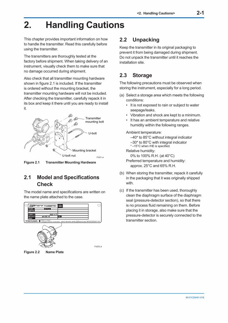
Also check that all transmitter mounting hardware showninfigure2.1isincluded.Ifthetransmitteris ordered without the mounting bracket, the transmitter mounting hardware will not be included. After checking the transmitter, carefully repack it in its box and keep it there until you are ready to install it.
F0201.ai
Mounting bracket
U-bolt nut
U-bolt
Transmittermounting bolt
Figure 2.1 Transmitter Mounting Hardware
2.1 Model and Specifications Check
Themodelnameandspecificationsarewrittenonthe name plate attached to the case.
F0202.ai
Figure 2.2 Name Plate
2.2 UnpackingKeep the transmitter in its original packaging to prevent it from being damaged during shipment. Do not unpack the transmitter until it reaches the installation site.
2.3 StorageThe following precautions must be observed when storing the instrument, especially for a long period.
(a) Select a storage area which meets the following conditions:• It is not exposed to rain or subject to water
seepage/leaks.• Vibration and shock are kept to a minimum.• It has an ambient temperature and relative
humidity within the following ranges.
Ambient temperature: –40* to 85°C without integral indicator –30* to 80°C with integral indicator
*–15°Cwhen/HEisspecified.Relative humidity: 0% to 100% R.H. (at 40°C)Preferred temperature and humidity: approx. 25°C and 65% R.H.
(b) When storing the transmitter, repack it carefully in the packaging that it was originally shipped with.
(c) If the transmitter has been used, thoroughly clean the diaphragm surface of the diaphragm seal (pressure-detector section), so that there isnoprocessfluidremainingonthem.Beforeplacing it in storage, also make sure that the pressure-detector is securely connected to the transmitter section.
<2. Handling Cautions> 2-2
IM 01C25H01-01E
2.4 Selecting the Installation Location
The transmitter is designed to withstand severe environmental conditions. However, to ensure that it will provide years of stable and accurate performance, take the following precautions when selecting the installation location.
(a) Ambient TemperatureAvoid locations subject to wide temperature variationsorasignificanttemperaturegradient.If the location is exposed to direct sunlight or radiant heat from plant equipment, provide adequate shade, thermal insulation and/or ventilation.
(b) Ambient AtmosphereDo not install the transmitter in a corrosive atmosphere. If this cannot be avoided, there must be adequate ventilation as well as measures to prevent the leaking of rain water and the presence of standing water in the conduits.
(c) Shock and VibrationAlthough the transmitter is designed to be relatively resistant to shock and vibration, an installation site should be selected where this is kept to a minimum.
(d) Installation of Explosion-protected TransmittersAn explosion-protected transmitters is certifiedforinstallationinahazardousareacontainingspecificgastypes.Seesubsection2.9 “Installation of an Explosion-Protected Transmitters.”
2.5 Pressure Connection
CAUTION
• Neverloosentheprocessflangeboltswhenan instrument is installed in a process. The device is under pressure, and a loss of seal can result in a sudden and uncontrolled releaseofprocessfluid.
• Sincetheaccumulatedprocessfluidmaybetoxic or otherwise harmful, take appropriate stepstopreventthecontactofsuchfluidswith the skin or eyes and the inhalation ofvaporsfromthesefluidsevenafterdismounting the instrument from process line for maintenance.
The following precautions must be observed in order to safely operate the transmitter under pressure.
(a) Make sure that there are no leaks in the impulse piping.
(b) Never apply a pressure higher than the specifiedmaximumworkingpressure.
2.6 Waterproofing of Cable Conduit Connections
Apply a non-hardening sealant to the threads to waterproof the transmitter cable conduit connections.(Seefigure5.8,5.9and5.10.)
<2. Handling Cautions> 2-3
IM 01C25H01-01E
2.7 Restrictions on Use of Radio Transceivers
IMPORTANTAlthough the transmitter has been designed to resist high frequency electrical noise, if a radio transceiver is used near the transmitter or its externalwiring,thetransmittermaybeaffectedby high frequency noise pickup. To test this, start out from a distance of several meters and slowly approach the transmitter with the transceiver while observing the measurement loop for noise effects.Thereafterusethetransceiveroutsidetherangewherethenoiseeffectswerefirstobserved.
2.8 Insulation Resistance and Dielectric Strength Test
Since the transmitter has undergone insulation resistance and dielectric strength tests at the factory before shipment, normally these tests are not required. If the need arises to conduct these tests, heed the following:
(a) Do not perform such tests more frequently than is absolutely necessary. Even test voltages that do not cause visible damage to the insulation may degrade the insulation and reduce safety margins.
(b) Never apply a voltage exceeding 500 V DC (100 V DC with an internal lightning protector) for the insulation resistance test, nor a voltage exceeding 500 V AC (100 V AC with an internal lightning protector) for the dielectric strength test.
(c) Before conducting these tests, disconnect all signal lines from the transmitter terminals. The procedure for conducting these tests is as follows:
• Insulation Resistance Test
1) Short-circuit the + and – SUPPLY terminals in the terminal box. In case of 1 to 5 V output, short-circuit the SUPPLY+, SUPPLY – and A (VOUT +) terminals.
2) Turn OFF the insulation tester. Then connect the insulation tester plus (+) lead wire to the shorted SUPPLY terminals and the minus (–) leadwire to the grounding terminal.
3) Turn ON the insulation tester power and measure the insulation resistance. The voltage shouldbeappliedasbrieflyaspossibletoverifythattheinsulationresistanceisatleast20MΩ.
4) After completing the test and being very careful not to touch exposed conductors disconnect the insulationtesterandconnecta100kΩresistorbetween the grounding terminal and the short-circuiting SUPPLY terminals. Leave this resistor connected at least one second to discharge any static potential. Do not touch the terminals while it is discharging.
• Dielectric Strength Test
1) Short-circuit the + and – SUPPLY terminals in the terminal box. In case of 1 to 5 V output, short-circuit the SUPPLY+, SUPPLY – and A (VOUT +) terminals.
2) Turn OFF the dielectric strength tester. Then connect the tester between the shorted SUPPLY terminals and the grounding terminal. Be sure to connect the grounding lead of the dielectric strength tester to the ground terminal.
3) Set the current limit on the dielectric strength tester to 25 mA, then turn ON the power and gradually increase the test voltage from ‘0’ to thespecifiedvoltage.
4)Whenthespecifiedvoltageisreached,holditfor one minute.
5) After completing this test, slowly decrease the voltage to avoid any voltage surges.
<2. Handling Cautions> 2-4
IM 01C25H01-01E
2.9 Installation of an Explosion-Protected Instrument
NOTEFor FOUNDATION Fieldbus explosion protected type, please refer to IM 01C25T02-01E. For PROFIBUS PA explosion protected type, please refer to IM 01C25T04-01EN.
Ifacustomermakesarepairormodificationtoan intrinsically safe or explosionproof instrument and the instrument is not restored to its original condition, its intrinsically safe or explosionproof construction may be compromised and the instrument may be hazardous to operate. Please contact Yokogawa before making any repair or modificationtoaninstrument.
CAUTIONThisinstrumenthasbeentestedandcertifiedas being intrinsically safe or explosionproof. Please note that severe restrictions apply to this instrument’s construction, installation, external wiring, maintenance and repair. A failure to abide by these restrictions could make the instrument a hazard to operate.
WARNING
Maintaining the safety of explosionproof equipment requires great care during mounting, wiring, and piping. Safety requirements also place restrictions on maintenance and repair. Please read the following sections very carefully.
WARNING
The range setting switch must not be used in a hazardous area.
IMPORTANTFor combined approval typesOnce a device of multiple approval type is installed, it should not be re-installed using any other approval types. Apply a permanent mark in the check box of the selected approval type onthecertificationlabelonthetransmittertodistinguish it from unused approval types.
IMPORTANTAll the blind plugs which accompany the EJX/EJA-E transmitters upon shipment from the factoryarecertifiedbytheapplicableagencyincombination with those transmitters. The plugs whicharemarkedwiththesymbols“◊Ex”ontheirsurfacesarecertifiedonlyincombinationwith the EJX/EJA-E series transmitters.
2.9.1 FM Approval
a. FM Intrinsically Safe/Nonincendive for HART/BRAIN Protocol Type
Note 1. EJX/EJA-E Series pressure transmitters with optional code /FS1 are applicable for use in hazardous locations.
• Applicable Standard: FM 3600:2011 FM 3610:2010 FM 3611:2004 FM 3810:2005 ANSI/ISA-60079-0-2009 ANSI/ISA-60079-11-2009 ANSI/ISA-61010-1-2004 NEMA 250:1991
• Rating Intrinsically Safe for Class I, II, III Division 1, Groups A, B, C, D, E, F, G T4 Class I Zone 0 AEx ia IIC T4 Nonincendive for Class I, II, III Division 2 Groups A, B, C, D, F, G T4 Class I, Zone 2 Group IIC T4
• Ambient temperature: –60 to 60°C• Enclosure: Type 4X
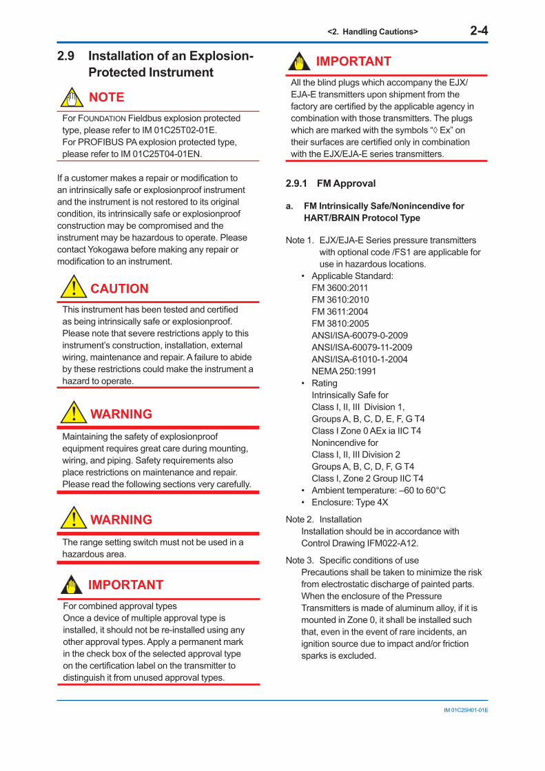
Note 2. InstallationInstallation should be in accordance with Control Drawing IFM022-A12.
Note3. SpecificconditionsofusePrecautions shall be taken to minimize the risk from electrostatic discharge of painted parts.When the enclosure of the Pressure Transmitters is made of aluminum alloy, if it is mounted in Zone 0, it shall be installed such that, even in the event of rare incidents, an ignition source due to impact and/or friction sparks is excluded.
<2. Handling Cautions> 2-5
IM 01C25H01-01E
Note 4. Maintenance and RepairOnly personnel authorized by Yokogawa Electric Corporation can repair the equipment.
Model: EJX Series Date: October 22, 2003
Rev.2: July 16, 2019 Doc. No.: IFM022-A12 P.1
Yokogawa Electric Corporation
Control Drawing
Class I, II, III, Division 1 Groups A, B, C, D, E, F, G Class I, Zone 0, Group IIC EJX Series Pressure Transmitter
Supply
Class I, II, Division 2 Groups A, B, C, D, F, G Class III, Division 1 Class I, Zone 2, Group IIC EJX Series Pressure Transmitter
Supply
(Refer to Note 4)
Associated Apparatus (Safety Barrier)
General Purpose Equipment
General Purpose Equipment
Model: EJX Series Date: October 22, 2003
Rev.3: July 16, 2019 Doc. No.: IFM022-A12 P.2
Yokogawa Electric Corporation
Specific conditions of use: - Precautions shall be taken to minimize the risk from electrostatic discharge of
painted parts. - When the enclosure of the Pressure Transmitters is made of aluminum alloy, if it is
mounted in Zone 0, it must be installed such that, even in the event of rare incidents, an ignition source due to impact and/or friction sparks is excluded.
Entity Parameters [Groups: A, B, C, D, E, F and G] Vmax: 30 V Imax: 200 mA Pmax: 1 W Ci: 6 nF Li: 0 µH Entity Parameters [Groups: C, D, E, F and G] Vmax: 30 V Imax: 225 mA Pmax: 1 W Ci: 6 nF Li: 0 µH Notes: 1. Installation must be in accordance with the National Electric Code (NFPA70),
ANSI/ISA-RP12.06.01, and relevant local codes. 2. The Associated Apparatus must be FM-approved. 3. The following conditions must be satisfied.
Voc (or Uo) ≤ Vmax Isc (or Io) ≤ Imax Po ≤ Pmax Ca (or Co) ≥ Ci + Ccable La (or Lo) ≥ Li + Lcable
4. In case Nonincendive Field Wiring Concept is used for the interconnection, FM-approved Associated Nonincendive Field Wiring Apparatus, which meets the above conditions, must be used as the General Purpose Equipment.
5. The General Purpose Equipment connected to the Associated Apparatus must not use or generate a voltage more than Um of the Associated Apparatus.
6. The control drawing of the Associated Apparatus must be followe d when installing the equipment.
7. Dust-tight conduit seals must be used when installed in Class II or Class III environments.
8. WARNING –ELECTROSTATIC CHARGE MAY CAUSE AN EXPLOSION HAZARD. AVOID ANY ACTIONS THAT CAUSE THE GENERATION OF ELECTROSTATIC CHARGE, SUCH AS RUBBING WITH A DRY CLOTH ON COATING FACE OF THE PRODUCT.
9. WARNING – SUBSTITUTION OF COMPONENTS MAY IMPAIR INTRINSIC SAFETY AND SUITABILITY FOR HAZARDOUS LOCATION
b. FM Explosionproof Type
Caution for FM explosionproof type.
Note 1. EJX/EJA-E Series pressure transmitters with optional code /FF1 are applicable for use in hazardous locations.
• Applicable Standard: FM3600:2018, FM3615:2018, FM3810:2018, NEMA 250:2003, ANSI/UL 61010-1:2012, ANSI/UL 61010-2-30:2012
• Explosionproof for Class I, Division 1, Groups B, C and D.
• Dust-ignitionproof for Class II/III, Division 1, Groups E, F and G.
• Enclosure: Type 4X• Temperature Class: T6• Ambient Temperature: –40 to 60°C• Supply Voltage: 42 V dc max.
32 V dc max. (FOUNDATION Fieldbus and PROFIBUS PA type)9 to 28 V dc, 27 mW (Low Power type)
• Output signal: 4 to 20 mA15 mA (FOUNDATION Fieldbus and PROFIBUS PA type)1 to 5 V (Low Power type)
Note 2. Wiring• All wiring shall comply with National Electrical
Code ANSI/NFPA70 and Local Electrical Codes.
• When installed in Division 1, “FACTORY SEALED, CONDUIT SEAL NOT REQUIRED.”
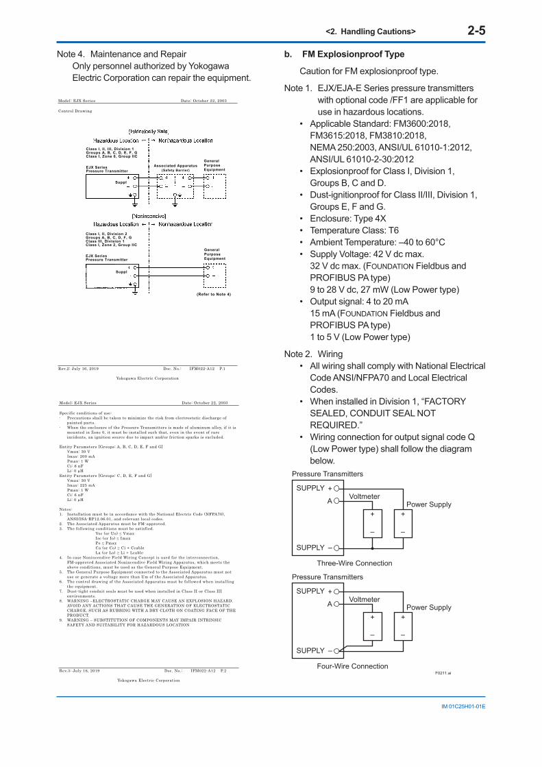
• Wiring connection for output signal code Q (Low Power type) shall follow the diagram below.
F0211.ai
Three-Wire Connection
Pressure Transmitters
Power SupplyVoltmeter
SUPPLY +
SUPPLY –
A
+
–
+
–
Four-Wire Connection
Pressure Transmitters
Power SupplyVoltmeter
SUPPLY +
SUPPLY –
A
+
–
+
–
<2. Handling Cautions> 2-6
IM 01C25H01-01E
Note 3. Operation• Keep the “WARNING” nameplate attached to
the transmitter. WARNING: OPEN CIRCUIT BEFORE
REMOVING COVER. FACTORY SEALED, CONDUIT SEAL NOT REQUIRED. INSTALL IN ACCORDANCE WITH THE USERS MANUAL IM 01C25.
• Take care not to generate mechanical sparking when accessing to the instrument and peripheral devices in a hazardous location.
Note 4. Maintenance and Repair• Theinstrumentmodificationorparts
replacement by other than authorized representative of Yokogawa Electric Corporation is prohibited and will void Factory Mutual Explosionproof Approval.
c. FM Intrinsically Safe Type/FM Explosionproof Type
EJX/EJA-E Series pressure transmitters with optional code /FU1 or /V1U1 can be selected the type of protection (FM Intrinsically Safe or FM Explosionproof) for use in hazardous locations.
Note 1. For the installation of this transmitter, once a particular type of protection is selected, any other type of protection cannot be used. The installation must be in accordance with the description about the type of protection in this instruction manual.
Note 2. In order to avoid confusion, cross out unnecessary markings on the label other than the selected type of protection when the transmitter is installed.
2.9.2 CSA Certification
a. CSA Intrinsically Safe Type
Caution for CSA Intrinsically safe and nonincendive type. (Following contents refer to “DOC No. ICS013-A13”)
Note1. EJX/EJA-ESeriesdifferential,gauge,and absolute pressure transmitters with optional code /CS1 are applicable for use in hazardous locations
Certificate:1606623
[For CSA C22.2]• Applicable Standard: C22.2 No.0, C22.2
No.0.4, C22.2 No.25, C22.2 No.94, C22.2 No.157, C22.2 No.213, C22.2 No.61010-1, C22.2 No.61010-2-030, C22.2 No.60079-0
• Intrinsically Safe for Class I, Division 1, Groups A, B, C & D, Class II, Division 1, Groups E, F & G, Class III, Division 1
• Nonincendive for Class I, Division 2, Groups A, B, C & D, Class II, Division 2, Groups F & G, Class III, Division 1
• Enclosure: Type 4X • Temp. Code: T4• Amb. Temp.:–50* to 60°C
*–15°Cwhen/HEisspecified.• Process Temperature: 120°C max.[For CSA E60079]• Applicable Standard: CAN/CSA E60079-11,
CAN/CSA E60079-15, IEC 60529:2001• Ex ia IIC T4, Ex nL IIC T4 • Ambient Temperature: –50* to 60°C
*–15°Cwhen/HEisspecified.• Max. Process Temp.: 120°C• Enclosure: IP66/IP67
Note 2. Entity Parameters• Intrinsically safe ratings are as follows: Maximum Input Voltage (Vmax/Ui) = 30 V Maximum Input Current (Imax/Ii) = 200 mA Maximum Input Power (Pmax/Pi) = 0.9 W Maximum Internal Capacitance (Ci) = 10 nF Maximum Internal Inductance (Li) = 0 µH• Type “n” or Nonincendive ratings are as
follows: Maximum Input Voltage (Vmax/Ui) = 30 V Maximum Internal Capacitance (Ci) = 10 nF Maximum Internal Inductance (Li) = 0 µH• Installation Requirements Uo≤Ui,Io≤Ii,Po≤Pi, Co≥Ci+Ccable,Lo≥Li+Lcable Voc≤Vmax,Isc≤Imax, Ca≥Ci+Ccable,La≥Li+Lcable Uo, Io, Po, Co, Lo, Voc, Isc, Ca and La are
parameters of barrier.
Note 3. Installation• In any safety barreir used output current
must be limited by a resistor ‘R’ such that Io=Uo/R or Isc=Voc/R.
• ThesafetybarriermustbeCSAcertified.• Input voltage of the safety barrier must be
less than 250 Vrms/Vdc.

<2. Handling Cautions> 2-7
IM 01C25H01-01E
• Installation should be in accordance with Canadian Electrical Code Part I and Local Electrical Code.
• Dust-tight conduit seal must be used when installed in Class II and III environments.
• Theinstrumentmodificationorpartsreplacement by other than authorized representative of Yokogawa Electric Corporation and Yokogawa Corporation of America is prohibited and will void Canadian Standards Intrinsically safe and nonincendiveCertification.
F0204-1.ai
Class I, II, III, Division 1,Groups A, B, C, D, E, F, G
Pressure Transmitters Safety Barrier
Supply
Hazardous Location Nonhazardous Location
General PurposeEquipment
+
–
+
–
+
–
+
–
[Intrinsically Safe]
Group IIC, Zone 0
F0204-2.ai
Pressure Transmitters
Supply
Hazardous Location Nonhazardous Location
+
–
+
–
Class I, II, Division 2,Groups A, B, C, D, F, GClass III, Division 1.
Not UseSafety Barrier
[Nonincendive]
CSA Certified Equipment([nL] or nonincendive)
Group IIC, Zone 2
b. CSA Explosionproof Type
Caution for CSA explosionproof type.
Note 1. EJX/EJA-E Series pressure transmitters with optional code /CF1 are applicable for use in hazardous locations:
• Certificate:2014354• Applicable Standard: C22.2 No.0,
C22.2 No.0.4, C22.2 No.0.5, C22.2 No.25, C22.2 No.30, C22.2 No.94, C22.2 No.61010-1, C22.2 No.61010-2-030, C22.2 No.60079-0, C22.2 No.60079-1
• Explosion-proof for Class I, Groups B, C and D.
• Dustignition-proof for Class II/III, Groups E, F and G.
• Enclosure: Type 4X
• Temperature Code: T6...T4• Ex d IIC T6...T4 • Enclosure: IP66/IP67• Maximum Process Temperature: 120°C (T4),
100°C (T5), 85°C (T6)• Ambient Temperature: –50* to 75°C (T4),
–50* to 80°C (T5), –50* to 75°C (T6)*–15°Cwhen/HEisspecified.
• Supply Voltage: 42 V dc max.32 V dc max. (FOUNDATION Fieldbus and PROFIBUS PA type)9 to 28 V dc, 27 mW (Low Power type)
• Output Signal: 4 to 20 mA dc15 mA (FOUNDATION Fieldbus and PROFIBUS PA type)1 to 5 V (Low Power type)
Note 2. Wiring• All wiring shall comply with Canadian
Electrical Code Part I and Local Electrical Codes.
• In hazardous location, wiring shall be in conduitasshowninthefigure.
• WARNING: A SEAL SHALL BE INSTALLED WITHIN
50cm OF THE ENCLOSURE. UN SCELLEMENT DOIT ÊTRE INSTALLÉ À
MOINS DE 50cm DU BOÎTIER.• WARNING: WHEN INSTALLED IN CL.I, DIV 2, SEAL
NOT REQUIRED. UNE FOIS INSTALLÉ DANS CL I, DIV 2,
AUCUN JOINT N’EST REQUIS.
Non-hazardous Location Equipment
42 V DC Max. 4 to 20 mA DC Signal
Non-Hazardous Locations
Hazardous Locations Division 1
50 cm Max.
Sealing FittingConduit
TransmitterF0205-1.ai
Non-Hazardous Locations
Hazardous Locations Division 2
Non-hazardous Location Equipment
42 V DC Max. 4 to 20 mA DC Signal
Sealing Fitting
TransmitterF0205-2.ai
<2. Handling Cautions> 2-8
IM 01C25H01-01E
• All wiring shall comply with local installation requirements and local electrical code.
• In hazardous locations, the cable entry devicesshallbeofacertifiedflameprooftype, suitable for the conditions of use and correctly installed.
• Unused apertures shall be closed with suitableflameproofcertifiedblankingelements.(Theplugattachedisflameproofcertified.)
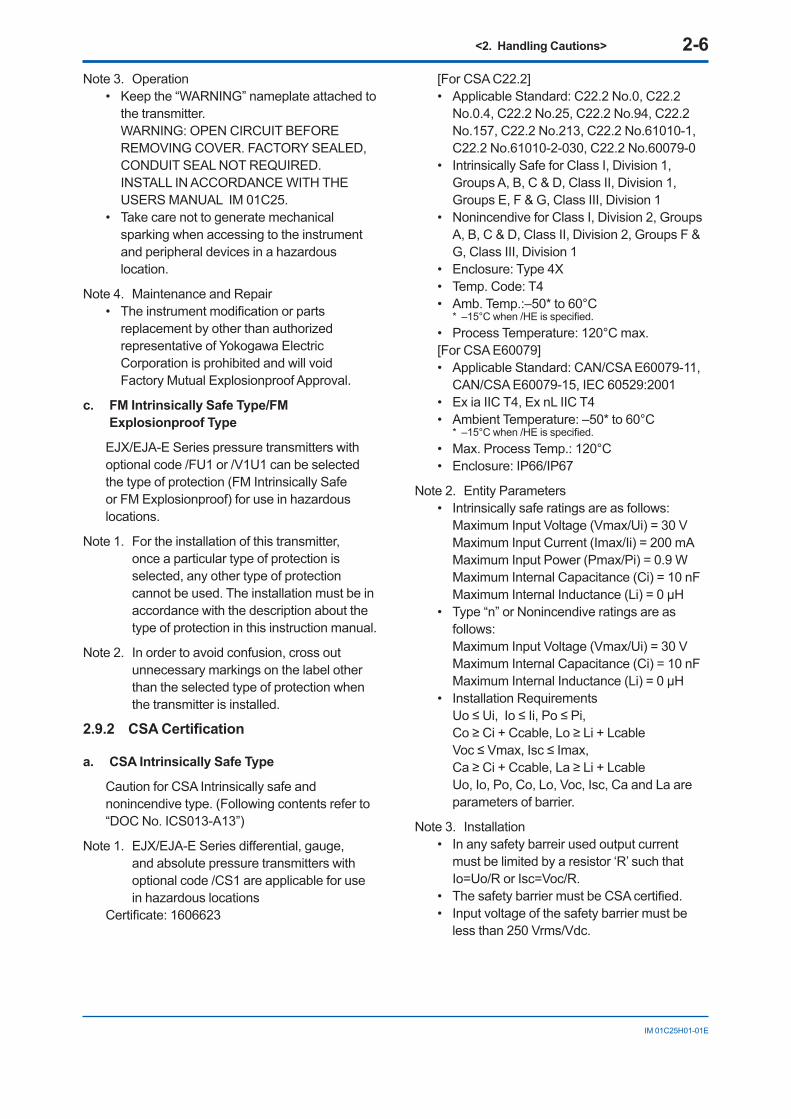
• Wiring connection for output signal code Q (Low Power type) shall follow the diagram below.
F0212.ai
Three-Wire Connection
Pressure Transmitters
Power SupplyVoltmeter
SUPPLY +
SUPPLY –
A
+
–
+
–
Four-Wire Connection
Pressure Transmitters
Power SupplyVoltmeter
SUPPLY +
SUPPLY –
A
+
–
+
–
Note 3. Operation• WARNING: AFTER DE-ENERGIZING, DELAY 5
MINUTES BEFORE OPENING. APRÉS POWER-OFF, ATTENDRE 5
MINUTES AVANT D’OUVRIR.• WARNING: WHENAMBIENTTEMPERATURE≥65°C,USETHEHEAT-RESISTINGCABLES≥90°C.
QUAND LA TEMPÉRATURE AMBIANTE ≥65°C,UTILISEZDESCÂBLESRÉSISTANTESÁLACHALEUR≥90°C.
• Take care not to generate mechanical sparking when accessing to the instrument and peripheral devices in a hazardous location.
Note 4. Maintenance and Repair• Theinstrumentmodificationorparts
replacement by other than authorized representative of Yokogawa Electric Corporation and Yokogawa Corporation of America is prohibited and will void Canadian StandardsExplosionproofCertification.
c CSA Intrinsically Safe Type/CSA Explosionproof Type
EJX/EJA-E Series pressure transmitters with optional code /CU1 or /V1U1 can be selected the type of protection (CSA Intrinsically Safe or CSA Explosionproof) for use in hazardous locations.
Note 1. For the installation of this transmitter, once a particular type of protection is selected, any other type of protection cannot be used. The installation must be in accordance with the description about the type of protection in this instruction manual.
Note 2. In order to avoid confusion, cross out unnecessary markings on the label other than the selected type of protection when the transmitter is installed.
2.9.3 ATEX Certification
(1) Technical Data
a. ATEX Intrinsically Safe Ex ia
Caution for ATEX Intrinsically safe type.
Note 1. EJX/EJA-E Series pressure transmitters with optional code /KS21 for use in hazardous locations:
• No. DEKRA 11ATEX0228 X• Applicable Standard:
EN 60079-0:2012+A11:2013 EN 60079-11:2012
• Type of Protection and Marking code: Ex ia IIC T4 Ga
Ex ia IIIC T85 ºC T100 ºC T120 ºC Db• Group: II• Category: 1G, 2D• Ambient Temperature for EPL Ga:
–50 to 60°C• Ambient Temperature for EPL Db:
–30* to 60°C*–15°Cwhen/HEisspecified.
<2. Handling Cautions> 2-9
IM 01C25H01-01E
• Process Temperature (Tp.): 120°C max.• Maximum Surface Temperature for EPL Db:
T85°C (Tp.: 80°C) T100°C (Tp.: 100°C) T120°C (Tp.: 120°C)
• Enclosure: IP66 / IP67 To satisfy IP66 or IP67, apply waterproof glands to the electrical connection port.
Note 2 Electrical Data• In type of explosion protection intrinsic safety
Ex ia IIC or Ex ia IIIC, only for connection to a certifiedintrinsicallysafecircuitwithfollowingmaximum values:
Ui = 30 V Ii = 200 mA Pi = 0.9 W (Linear Source) Maximum internal capacitance; Ci = 27.6 nF Maximum internal inductance; Li = 0 µH
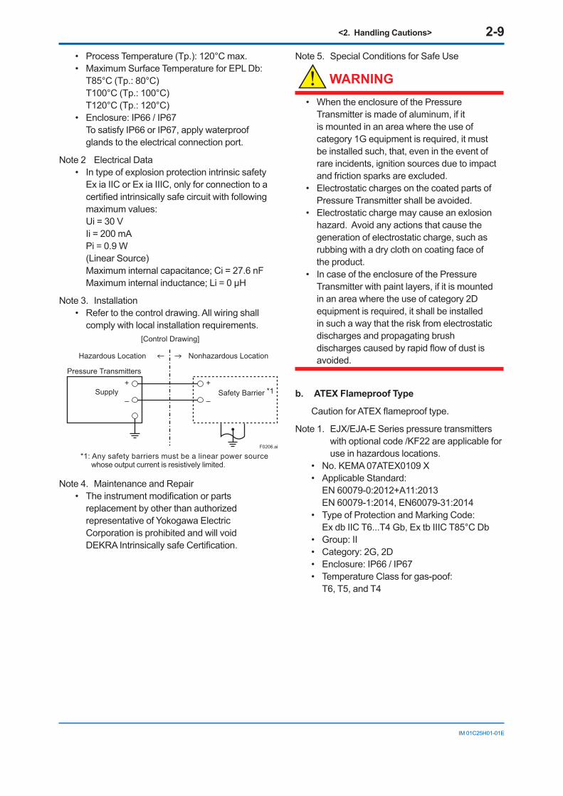
Note 3. Installation• Refer to the control drawing. All wiring shall
comply with local installation requirements.
Pressure Transmitters
Supply Safety Barrier *1
Nonhazardous Location
[Control Drawing]
Hazardous Location
+
–
+
–
F0206.ai
*1: Any safety barriers must be a linear power source whose output current is resistively limited.
Note 4. Maintenance and Repair• Theinstrumentmodificationorparts
replacement by other than authorized representative of Yokogawa Electric Corporation is prohibited and will void DEKRAIntrinsicallysafeCertification.
Note 5. Special Conditions for Safe Use
WARNING
• When the enclosure of the Pressure Transmitter is made of aluminum, if it is mounted in an area where the use of category 1G equipment is required, it must be installed such, that, even in the event of rare incidents, ignition sources due to impact and friction sparks are excluded.
• Electrostatic charges on the coated parts of Pressure Transmitter shall be avoided.
• Electrostatic charge may cause an exlosion hazard. Avoid any actions that cause the generation of electrostatic charge, such as rubbing with a dry cloth on coating face of the product.
• In case of the enclosure of the Pressure Transmitter with paint layers, if it is mounted in an area where the use of category 2D equipment is required, it shall be installed in such a way that the risk from electrostatic discharges and propagating brush dischargescausedbyrapidflowofdustisavoided.
b. ATEX Flameproof Type
CautionforATEXflameprooftype.
Note 1. EJX/EJA-E Series pressure transmitters with optional code /KF22 are applicable for use in hazardous locations.
• No. KEMA 07ATEX0109 X• Applicable Standard:
EN 60079-0:2012+A11:2013 EN 60079-1:2014, EN60079-31:2014
• Type of Protection and Marking Code: Ex db IIC T6...T4 Gb, Ex tb IIIC T85°C Db
• Group: II• Category: 2G, 2D• Enclosure: IP66 / IP67• Temperature Class for gas-poof:
T6, T5, and T4
<2. Handling Cautions> 2-10
IM 01C25H01-01E
• Ambient Temperature for gas-proof: –50 to 75°C (T6), –50 to 80°C (T5), and –50 to 75°C (T4)
• Process Temperature (Tp.) for gas-proof: –50 to 85°C (T6), –50 to 100°C (T5), and –50 to 120°C (T4)
• Maximum Surface Temperature for dust-proof: T85°C (Tamb.: –30* to 75°C, Tp.: –30* to 85°C) *–15°Cwhen/HEisspecified.
Note 2. Electrical Data• Supply voltage: 42 V dc max. 32 V dc max. (FOUNDATION Fieldbus and
PROFIBUS PA type) 9 to 28 V dc, 27 mW (Low Power type) 9 to 30 V dc, 250 mW (RS485 Modbus
Communication Type)• Output signal: 4 to 20 mA 15 mA (FOUNDATION Fieldbus and
PROFIBUS PA type) 1 to 5 V (Low Power type) RS485 Modbus (RS485 Modbus
Communication Type)
Note 3. Installation• All wiring shall comply with local installation
requirement.• Cable glands, adapters and/or blanking
elements with a suitable IP rating shall beofExdIIC/ExtbIIICcertifiedbyATEXand shall be installed so as to maintain the specificdegreeofprotection(IPCode)oftheequipment.
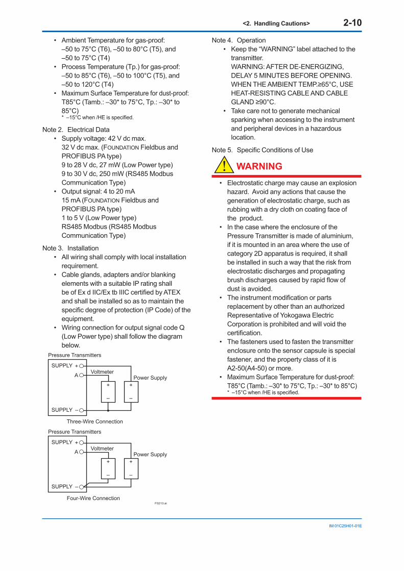
• Wiring connection for output signal code Q (Low Power type) shall follow the diagram below.
F0213.ai
Three-Wire Connection
Pressure Transmitters
Power SupplyVoltmeter
SUPPLY +
SUPPLY –
A
+
–
+
–
Four-Wire Connection
Pressure Transmitters
Power SupplyVoltmeter
SUPPLY +
SUPPLY –
A
+
–
+
–
Note 4. Operation• Keep the “WARNING” label attached to the
transmitter. WARNING: AFTER DE-ENERGIZING,
DELAY 5 MINUTES BEFORE OPENING. WHENTHEAMBIENTTEMP.≥65°C,USEHEAT-RESISTING CABLE AND CABLE GLAND≥90°C.
• Take care not to generate mechanical sparking when accessing to the instrument and peripheral devices in a hazardous location.
Note5. SpecificConditionsofUse
WARNING
• Electrostatic charge may cause an explosion hazard. Avoid any actions that cause the generation of electrostatic charge, such as rubbing with a dry cloth on coating face of the product.
• In the case where the enclosure of the Pressure Transmitter is made of aluminium, if it is mounted in an area where the use of category 2D apparatus is required, it shall be installed in such a way that the risk from electrostatic discharges and propagating brushdischargescausedbyrapidflowofdust is avoided.
• Theinstrumentmodificationorpartsreplacement by other than an authorized Representative of Yokogawa Electric Corporation is prohibited and will void the certification.
• The fasteners used to fasten the transmitter enclosure onto the sensor capsule is special fastener, and the property class of it is A2-50(A4-50) or more.
• Maximum Surface Temperature for dust-proof: T85°C (Tamb.: –30* to 75°C, Tp.: –30* to 85°C) *–15°Cwhen/HEisspecified.
<2. Handling Cautions> 2-11
IM 01C25H01-01E
c. ATEX Intrinsically Safe Type/ATEX Flameproof Type
EJX/EJA-E Series pressure transmitters with optional code /KU22 or /V1U1 can be selected the type of protection ATEX Flameproof, Intrinsically Safe. Ex ia, or Ex ic for use in hazardous area.
Note 1. For the installation of this transmitter, once a particular type of protection is selected, any other type of protection cannot be used. The installation must be in accordance with the description about the type of protection in this user’s manual.
Note 2. For combined approval types Once a device of multiple approval type is installed, it should not be re-installed using any other approval types. Apply a permanent mark in the check box of the selected approvaltypeonthecertificationlabelonthe transmitter to distinguish it from unused approval types.
ATEX Intrinsically Safe Ex ic
Caution for ATEX intrinsically safe Ex ic• Applicable Standard:
EN 60079-0:2012+A11:2013 EN 60079-11:2012
• Type of Protection and Marking Code: II 3G Ex ic IIC T4 Gc
• Ambient Temperature: –30* to +60°C*–15°Cwhen/HEisspecified.
• Ambient Humidity: 0 to 100% (No condensation)
• Maximum Process Temperature: 120°C• IP Code: IP66• Ambient pollution degree: 2• Overvoltage category: I
Note 1. Electrical Data Ui = 30 V Ci = 27.6 nF Li = 0 µH
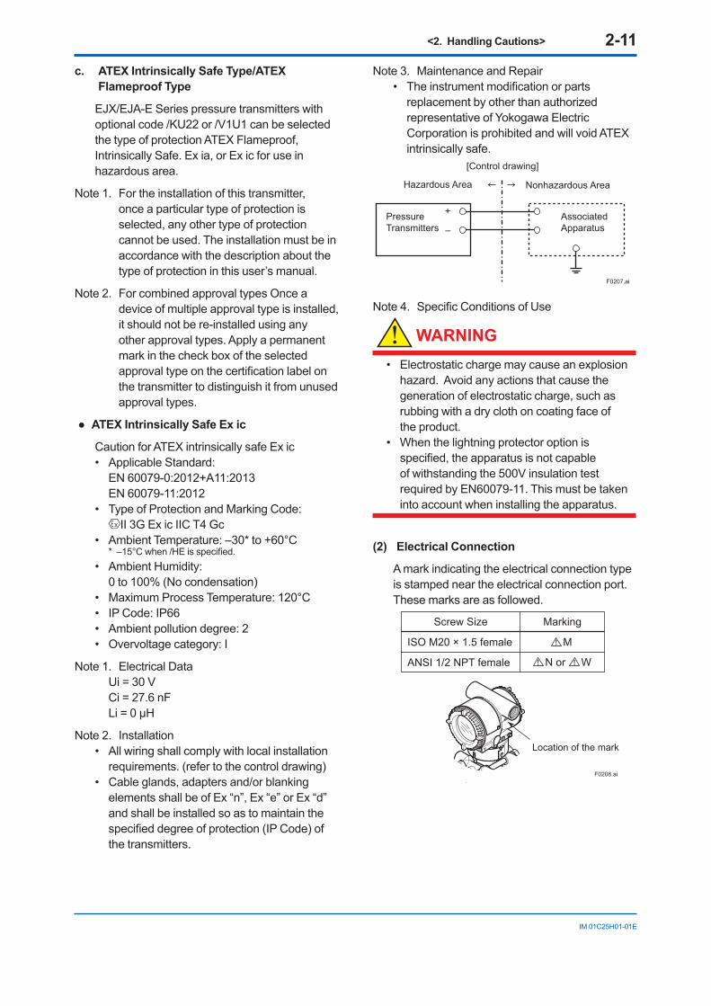
Note 2. Installation• All wiring shall comply with local installation
requirements. (refer to the control drawing)• Cable glands, adapters and/or blanking
elements shall be of Ex “n”, Ex “e” or Ex “d” and shall be installed so as to maintain the specifieddegreeofprotection(IPCode)ofthe transmitters.
Note 3. Maintenance and Repair• Theinstrumentmodificationorparts
replacement by other than authorized representative of Yokogawa Electric Corporation is prohibited and will void ATEX intrinsically safe.
Associated Apparatus
PressureTransmitters
Nonhazardous Area
[Control drawing]
Hazardous Area
+
–
F0207.ai
Note4. SpecificConditionsofUse
WARNING
• Electrostatic charge may cause an explosion hazard. Avoid any actions that cause the generation of electrostatic charge, such as rubbing with a dry cloth on coating face of the product.
• When the lightning protector option is specified,theapparatusisnotcapableof withstanding the 500V insulation test required by EN60079-11. This must be taken into account when installing the apparatus.
(2) Electrical Connection
A mark indicating the electrical connection type is stamped near the electrical connection port. These marks are as followed.
F0208.ai
Location of the mark
Screw Size Marking
ISO M20 × 1.5 female
ANSI 1/2 NPT female
M
N or W
<2. Handling Cautions> 2-12
IM 01C25H01-01E
(3) Installation
WARNING
• All wiring shall comply with local installation requirements and the local electrical code.
• There is no need for conduit seal in Division 1 and Division 2 hazardous locations because this product is sealed at the factory.
(4) Operation
WARNING
• OPEN CIRCUIT BEFORE REMOVING COVER. INSTALL IN ACCORDANCE WITH THIS USER’S MANUAL
• Take care not to generate mechanical sparking when access to the instrument and peripheral devices in a hazardous location.
(5) Maintenance and Repair
WARNING
Theinstrumentmodificationorpartsreplacementby other than an authorized Representative of Yokogawa Electric Corporation is prohibited and willvoidthecertification.
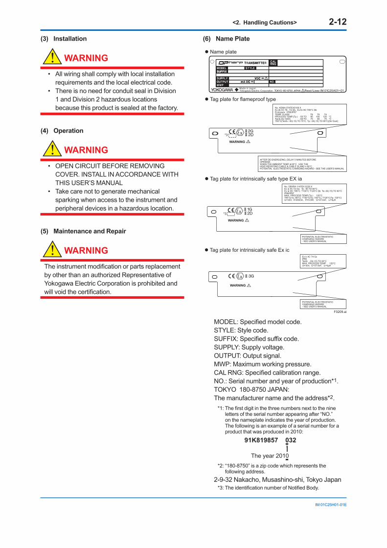
(6) Name Plate
Tag plate for intrinsically safe Ex ic
WARNING
Ex ic IIC T4 GcIP66Tamb -30(-15) TO 60°C MAX. PROCESS TEMP. 120°CUi=30V, Ci=27.6nF, Li=0µH
POTENTIAL ELECTROSTATIC CHARGING HAZARD- SEE USER’S MANUAL
Name plate
Tag plate for flameproof type
Tag plate for intrinsically safe type EX ia
F0209.ai
WARNING
D
DWARNING
No. KEMA 07ATEX0109 XEx db IIC T6...T4 Gb, Ex tb IIIC T85°C DbEnlcosure : IP66/IP67TEMP. CLASS T6 T5 T4PROCESS TEMP.(Tp.) -50 TO 85 100 120 °CTamb.(for GAS) -50 TO 75 80 75 °CT85°C(Tamb.:-30(-15) TO 75°C, Tp.:-30(-15) TO 85°C)(for Dust)
No. DEKRA 11ATEX 0228 X Ex ia IIC T4 Ga Ta: -50 TO 60°CEx ia IIIC T85°C T100°C T120°C Db Ta:-30(-15) TO 60°CIP66/IP67MAX. PROCESS TEMP.(Tp.) 120°CT85°C(Tp.:80°C), T100°C(Tp.:100°C), T120°C(Tp.:120°C)Ui=30V, Ii=200mA , Pi=0.9W, Ci=27.6nF, Li=0µH
POTENTIAL ELECTROSTATIC CHARGING HAZARD- SEE USER’S MANUAL
AFTER DE-ENERGIZING, DELAY 5 MINUTES BEFORE OPENING. WHEN THE AMBIENT TEMP. ≥ 65°C, USE THE HEAT-RESISTING CABLE & CABLE GLAND ≥ 90°CPOTENTIAL ELECTROSTATIC CHARGING HAZARD - SEE THE USER’S MANUAL
*3
*3
MODEL:Specifiedmodelcode.STYLE: Style code.SUFFIX:Specifiedsuffixcode.SUPPLY: Supply voltage.OUTPUT: Output signal. MWP: Maximum working pressure. CALRNG:Specifiedcalibrationrange.NO.: Serial number and year of production*1.TOKYO 180-8750 JAPAN: The manufacturer name and the address*2.
*1:Thefirstdigitinthethreenumbersnexttothenineletters of the serial number appearing after “NO.” on the nameplate indicates the year of production. The following is an example of a serial number for a product that was produced in 2010:
The year 2010
91K819857 032
*2: “180-8750” is a zip code which represents the following address.
2-9-32 Nakacho, Musashino-shi, Tokyo Japan *3:TheidentificationnumberofNotifiedBody.
<2. Handling Cautions> 2-13
IM 01C25H01-01E
2.9.4 IECEx CertificationEJX Series pressure transmitters with optional code /SU21 can be selected the type of protection (IECEx Intrinsically Safe Ex ia, Ex ic orflameproof)foruseinhazardouslocations.
Note 1. For the installation of this transmitter, once a particular type of protection is selected, any other type of protection cannot be used. The installation must be in accordance with the description about the type of protection in this instruction manual.
Note 2. For combined approval types, once a device of multiple approval type is installed, it should not be re-installed using any other approval types. Apply a permanent mark in the check box of the selected approvaltypeonthecertificationlabelonthe transmitter to distinguish it from unused approval types.
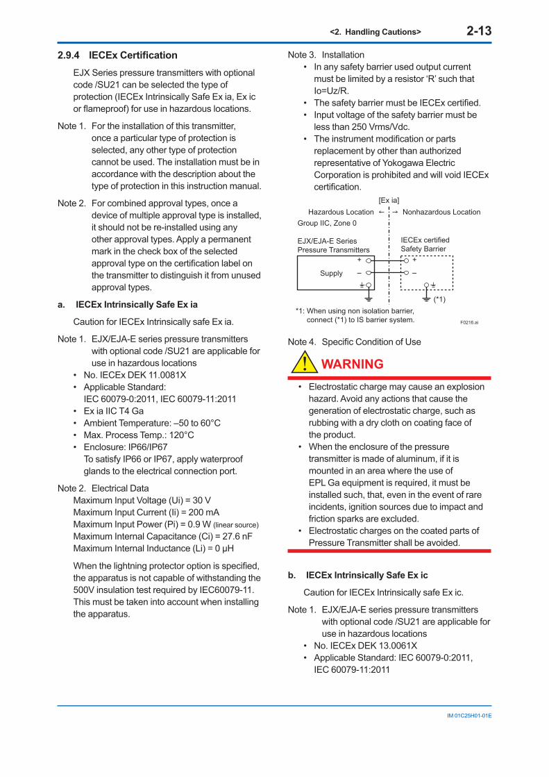
a. IECEx Intrinsically Safe Ex ia
Caution for IECEx Intrinsically safe Ex ia.
Note 1. EJX/EJA-E series pressure transmitters with optional code /SU21 are applicable for use in hazardous locations
• No. IECEx DEK 11.0081X • Applicable Standard:
IEC 60079-0:2011, IEC 60079-11:2011 • Ex ia IIC T4 Ga • Ambient Temperature: –50 to 60°C• Max. Process Temp.: 120°C • Enclosure: IP66/IP67 To satisfy IP66 or IP67, apply waterproof
glands to the electrical connection port.
Note 2. Electrical DataMaximum Input Voltage (Ui) = 30 V Maximum Input Current (Ii) = 200 mA Maximum Input Power (Pi) = 0.9 W (linear source)Maximum Internal Capacitance (Ci) = 27.6 nF MaximumInternalInductance(Li)=0μH
Whenthelightningprotectoroptionisspecified,the apparatus is not capable of withstanding the 500V insulation test required by IEC60079-11. This must be taken into account when installing the apparatus.
Note 3. Installation • In any safety barrier used output current
must be limited by a resistor ‘R’ such that Io=Uz/R.
• ThesafetybarriermustbeIECExcertified.• Input voltage of the safety barrier must be
less than 250 Vrms/Vdc. • Theinstrumentmodificationorparts
replacement by other than authorized representative of Yokogawa Electric Corporation is prohibited and will void IECEx certification.
F0216.ai
EJX/EJA-E Series Pressure Transmitters
IECEx certifiedSafety Barrier
Supply
Hazardous Location Nonhazardous Location
+
–
+
–
[Ex ia]
Group IIC, Zone 0
(*1)*1: When using non isolation barrier,
connect (*1) to IS barrier system.
Note4. SpecificConditionofUse
WARNING
• Electrostatic charge may cause an explosion hazard. Avoid any actions that cause the generation of electrostatic charge, such as rubbing with a dry cloth on coating face of the product.
• When the enclosure of the pressure transmitter is made of aluminum, if it is mounted in an area where the use of EPL Ga equipment is required, it must be installed such, that, even in the event of rare incidents, ignition sources due to impact and friction sparks are excluded.
• Electrostatic charges on the coated parts of Pressure Transmitter shall be avoided.
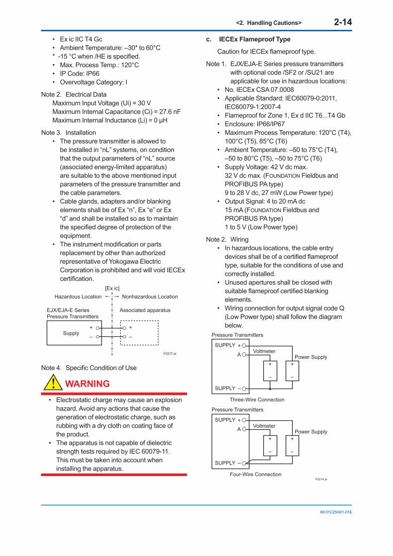
b. IECEx Intrinsically Safe Ex ic
Caution for IECEx Intrinsically safe Ex ic.
Note 1. EJX/EJA-E series pressure transmitters with optional code /SU21 are applicable for use in hazardous locations
• No. IECEx DEK 13.0061X • Applicable Standard: IEC 60079-0:2011,
IEC 60079-11:2011
<2. Handling Cautions> 2-14
IM 01C25H01-01E
• Ex ic IIC T4 Gc • Ambient Temperature: –30* to 60°C*-15°Cwhen/HEisspecified.• Max. Process Temp.: 120°C • IP Code: IP66• Overvoltage Category: I
Note 2. Electrical Data Maximum Input Voltage (Ui) = 30 V Maximum Internal Capacitance (Ci) = 27.6 nF MaximumInternalInductance(Li)=0μH
Note 3. Installation • The pressure transmitter is allowed to
be installed in “nL” systems, on condition that the output parameters of “nL” source (associated energy-limited apparatus) are suitable to the above mentioned input parameters of the pressure transmitter and the cable parameters.
• Cable glands, adapters and/or blanking elements shall be of Ex “n”, Ex “e” or Ex “d” and shall be installed so as to maintain thespecifieddegreeofprotectionoftheequipment.
• Theinstrumentmodificationorpartsreplacement by other than authorized representative of Yokogawa Electric Corporation is prohibited and will void IECEx certification.
F0217.ai
EJX/EJA-E Series Pressure Transmitters
Associated apparatus
Supply
Hazardous Location Nonhazardous Location
+
–
+
–
[Ex ic]
Note4. SpecificConditionofUse
WARNING
• Electrostatic charge may cause an explosion hazard. Avoid any actions that cause the generation of electrostatic charge, such as rubbing with a dry cloth on coating face of the product.
• The apparatus is not capable of dielectric strength tests required by IEC 60079-11. This must be taken into account when installing the apparatus.
c. IECEx Flameproof Type
CautionforIECExflameprooftype.
Note 1. EJX/EJA-E Series pressure transmitters with optional code /SF2 or /SU21 are applicable for use in hazardous locations:
• No. IECEx CSA 07.0008• Applicable Standard: IEC60079-0:2011,
IEC60079-1:2007-4• Flameproof for Zone 1, Ex d IIC T6...T4 Gb• Enclosure: IP66/IP67• Maximum Process Temperature: 120°C (T4),
100°C (T5), 85°C (T6)• Ambient Temperature: –50 to 75°C (T4),
–50 to 80°C (T5), –50 to 75°C (T6)• Supply Voltage: 42 V dc max.
32 V dc max. (FOUNDATION Fieldbus and PROFIBUS PA type)9 to 28 V dc, 27 mW (Low Power type)
• Output Signal: 4 to 20 mA dc15 mA (FOUNDATION Fieldbus and PROFIBUS PA type)1 to 5 V (Low Power type)
Note 2. Wiring• In hazardous locations, the cable entry devicesshallbeofacertifiedflameprooftype, suitable for the conditions of use and correctly installed.
• Unused apertures shall be closed with suitableflameproofcertifiedblankingelements.
• Wiring connection for output signal code Q (Low Power type) shall follow the diagram below.
F0214.ai
Three-Wire Connection
Pressure Transmitters
Power SupplyVoltmeter
SUPPLY +
SUPPLY –
A
+
–
+
–
Four-Wire Connection
Pressure Transmitters
Power SupplyVoltmeter
SUPPLY +
SUPPLY –
A
+
–
+
–
<2. Handling Cautions> 2-15
IM 01C25H01-01E
Note 3. Operation• WARNING:
AFTER DE-ENERGIZING, DELAY 5 MINUTES BEFORE OPENING.
• WARNING: WHENTHEAMBIENTTEMP.≥65°C,USE
HEAT-RESISTING CABLE AND CABLE GLAND≥90°C.
• Take care not to generate mechanical sparking when accessing to the instrument and peripheral devices in a hazardous location.
• Electrostatic charge may cause an explosion hazard. Avoid any actions that cause the generation of electrostatic charge, such as rubbing with a dry cloth on coating face of the product.
Note 4. Maintenance and Repair• Theinstrumentmodificationorparts
replacement by other than authorized representative of Yokogawa Electric Corporation is prohibited and will void IECEx Certification.
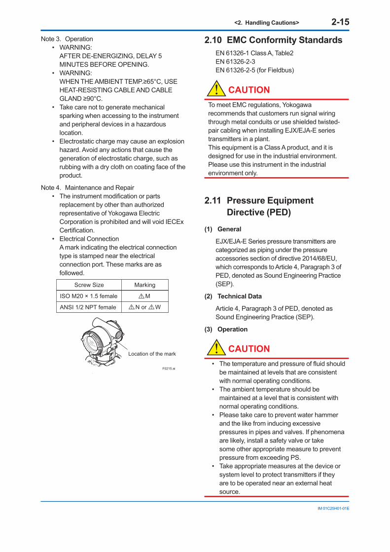
• Electrical ConnectionA mark indicating the electrical connection type is stamped near the electrical connection port. These marks are as followed.
F0215.ai
Location of the mark
Screw Size Marking
ISO M20 × 1.5 female
ANSI 1/2 NPT female
M
N or W
2.10 EMC Conformity StandardsEN 61326-1 Class A, Table2 EN 61326-2-3EN 61326-2-5 (for Fieldbus)
CAUTIONTo meet EMC regulations, Yokogawa recommends that customers run signal wiring through metal conduits or use shielded twisted-pair cabling when installing EJX/EJA-E series transmitters in a plant.This equipment is a Class A product, and it is designed for use in the industrial environment. Please use this instrument in the industrial environment only.
2.11 Pressure Equipment Directive (PED)
(1) General
EJX/EJA-E Series pressure transmitters are categorized as piping under the pressure accessories section of directive 2014/68/EU, which corresponds to Article 4, Paragraph 3 of PED, denoted as Sound Engineering Practice (SEP).
(2) Technical Data
Article 4, Paragraph 3 of PED, denoted as Sound Engineering Practice (SEP).
(3) Operation
CAUTION• Thetemperatureandpressureoffluidshould
be maintained at levels that are consistent with normal operating conditions.
• The ambient temperature should be maintained at a level that is consistent with normal operating conditions.
• Please take care to prevent water hammer and the like from inducing excessive pressures in pipes and valves. If phenomena are likely, install a safety valve or take some other appropriate measure to prevent pressure from exceeding PS.
• Take appropriate measures at the device or system level to protect transmitters if they are to be operated near an external heat source.
<2. Handling Cautions> 2-16
IM 01C25H01-01E
2.12 EU RoHS DirectiveApplicable standard: EN 50581
Applicable production sites are shown below. The condition of the RoHS compliant production sites are as follows: Japan, USA, Germany, Bahrain, India
Theproductionsitescanbeconfirmedbytheserial number shown in the frame of “NO.” in the name plate of the product.
Serial numbers (9 letters): AAnnnnnnn AA:Identificationcodeofproductionsite
Japan: Use “91” USA: Use “U1”Germany: Use “D1” Bahrain: Use “BH”India: Use “Y1”
2.13 Safety Requirement Standards
Applicable standard: EN 61010-1, C22.2 No.61010-1
(1) Pollution Degree 2
"Pollution degree" describes the degree to which a solid, liquid, or gas which deteriorates dielectric strength or surface resistivity is adhering. " 2 " applies to normal indoor atmosphere. Normally, only non-conductive pollution occurs. Occasionally, however, temporary conductivity caused by condensation must be expected.
(2) Installation Category I
"Overvoltage category (Installation category)" describesanumberwhichdefinesatransientovervoltage condition. It implies the regulattion for impulse withstand voltage. " I " applies to electrical equipment which is supplied from the circuit when appropriate transient overvoltage control means (interfaces) are provided.
(3) Indoor/Outdoor use
<3. Component Names> 3-1
IM 01C25H01-01E
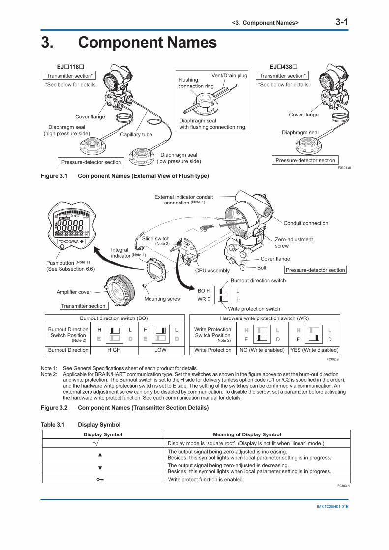
3. Component Names
F0301.ai
Diaphragm sealwith flushing connection ring
Transmitter section**See below for details.
Pressure-detector section
Cover flange
Diaphragm seal(high pressure side)
Diaphragm seal(low pressure side)
Capillary tube
Vent/Drain plugFlushingconnection ring
Transmitter section**See below for details.
Pressure-detector section
Cover flange
Diaphragm seal
EJ118 EJ438
Figure 3.1 Component Names (External View of Flush type)
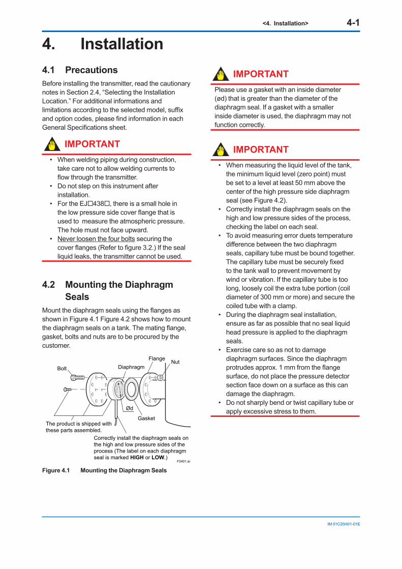
HIGH LOW
H L H L H L
E D
H L
E D
YES (Write disabled)NO (Write enabled)F0302.ai
Cover flange
CPU assembly
Integralindicator (Note 1)
Amplifier cover
Conduit connection
Zero-adjustment screw
Pressure-detector section
External indicator conduit connection (Note 1)
Transmitter section
Slide switch(Note 2)
Mounting screw
Push button (Note 1)
(See Subsection 6.6)
Burnout DirectionSwitch Position
Burnout direction switch (BO)
Burnout Direction
Write ProtectionSwitch Position
Write Protection
Hardware write protection switch (WR)
Bolt
(Note 2)(Note 2)
BO H LWR E D
Burnout direction switch
Write protection switch
Note1: SeeGeneralSpecificationssheetofeachproductfordetails.Note2: ApplicableforBRAIN/HARTcommunicationtype.Settheswitchesasshowninthefigureabovetosettheburn-outdirection
andwriteprotection.TheBurnoutswitchissettotheHsidefordelivery(unlessoptioncode/C1or/C2isspecifiedintheorder),andthehardwarewriteprotectionswitchissettoEside.Thesettingoftheswitchescanbeconfirmedviacommunication.Anexternal zero adjustment screw can only be disabled by communication. To disable the screw, set a parameter before activating the hardware write protect function. See each communication manual for details.
Figure 3.2 Component Names (Transmitter Section Details)
Table 3.1 Display Symbol
F0303.ai
Display Symbol Meaning of Display SymbolDisplay mode is ‘square root’. (Display is not lit when ‘linear’ mode.)The output signal being zero-adjusted is increasing. Besides, this symbol lights when local parameter setting is in progress.The output signal being zero-adjusted is decreasing. Besides, this symbol lights when local parameter setting is in progress.Write protect function is enabled.
<4. Installation> 4-1
IM 01C25H01-01E
4. Installation4.1 Precautions Before installing the transmitter, read the cautionary notes in Section 2.4, “Selecting the Installation Location.” For additional informations and limitationsaccordingtotheselectedmodel,suffixandoptioncodes,pleasefindinformationineachGeneralSpecificationssheet.
IMPORTANT• When welding piping during construction,
take care not to allow welding currents to flowthroughthetransmitter.
• Do not step on this instrument after installation.
• For the EJ438, there is a small hole in thelowpressuresidecoverflangethatisused to measure the atmospheric pressure. The hole must not face upward.
• Never loosen the four bolts securing the coverflanges(Refertofigure3.2.)Ifthesealliquid leaks, the transmitter cannot be used.
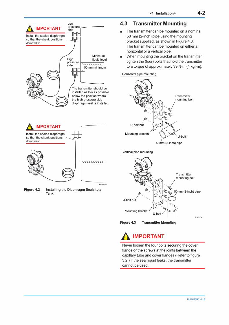
4.2 Mounting the Diaphragm Seals
Mountthediaphragmsealsusingtheflangesasshown in Figure 4.1 Figure 4.2 shows how to mount thediaphragmsealsonatank.Thematingflange,gasket, bolts and nuts are to be procured by the customer.
NutFlangeDiaphragm
Ød
Gasket
F0401.ai
Bolt
The product is shipped withthese parts assembled.
Correctly install the diaphragm seals onthe high and low pressure sides of theprocess (The label on each diaphragm seal is marked HIGH or LOW.)
Figure 4.1 Mounting the Diaphragm Seals
IMPORTANTPlease use a gasket with an inside diameter (ød) that is greater than the diameter of the diaphragm seal. If a gasket with a smaller inside diameter is used, the diaphragm may not function correctly.
IMPORTANT• When measuring the liquid level of the tank,
the minimum liquid level (zero point) must be set to a level at least 50 mm above the center of the high pressure side diaphragm seal (see Figure 4.2).
• Correctly install the diaphragm seals on the high and low pressure sides of the process, checking the label on each seal.
• To avoid measuring error duets temperature differencebetweenthetwodiaphragmseals, capillary tube must be bound together. Thecapillarytubemustbesecurelyfixedto the tank wall to prevent movement by wind or vibration. If the capillary tube is too long, loosely coil the extra tube portion (coil diameter of 300 mm or more) and secure the coiled tube with a clamp.
• During the diaphragm seal installation, ensure as far as possible that no seal liquid head pressure is applied to the diaphragm seals.
• Exercise care so as not to damage diaphragm surfaces. Since the diaphragm protrudes approx.1mmfromtheflangesurface, do not place the pressure detector section face down on a surface as this can damage the diaphragm.
• Do not sharply bend or twist capillary tube or apply excessive stress to them.
<4. Installation> 4-2
IM 01C25H01-01E
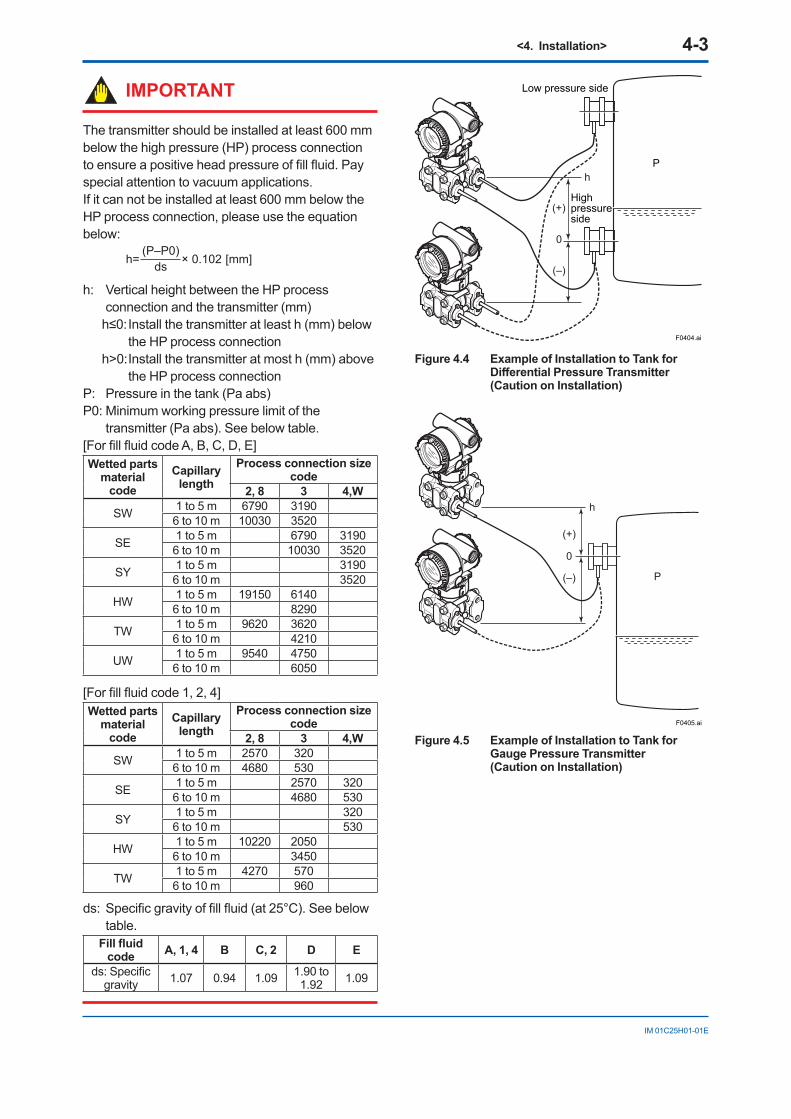
F0402.ai
50mm minimum
Minimum liquid levelHigh
pressureside
Install the sealed diaphragm so that the shank positions downward.
Low pressure sideIMPORTANT
The transmitter should be installed as low as possible below the position where the high pressure side diaphragm seal is installed.
Install the sealed diaphragm so that the shank positions downward.
IMPORTANT
Figure 4.2 Installing the Diaphragm Seals to a Tank
4.3 Transmitter Mounting Thetransmittercanbemountedonanominal
50 mm (2-inch) pipe using the mounting bracket supplied, as shown in Figure 4.3. The transmitter can be mounted on either a horizontal or a vertical pipe.
Whenmountingthebracketonthetransmitter,tighten the (four) bolts that hold the transmitter to a torque of approximately 39 N·m 4 kgf·m.
F0403.ai
U-bolt nut
Mounting bracket
Mounting bracket
50mm (2-inch) pipe
U-bolt
U-bolt
Horizontal pipe mounting
50mm (2-inch) pipe
Transmittermounting bolt
Transmittermounting bolt
U-bolt nut
Vertical pipe mounting
Figure 4.3 Transmitter Mounting
IMPORTANTNever loosen the four bolts securing the cover flangeor the screws at the joints between the capillarytubeandcoverflanges(Refertofigure3.2.) If the seal liquid leaks, the transmitter cannot be used.
<4. Installation> 4-3
IM 01C25H01-01E
F0404.ai
P
Low pressure side
Highpressureside
(+)
(–)
0
h
Figure 4.4 Example of Installation to Tank for Differential Pressure Transmitter (Caution on Installation)
F0405.ai
(+)
0
(–) P
h
Figure 4.5 Example of Installation to Tank for Gauge Pressure Transmitter (Caution on Installation)
IMPORTANT
The transmitter should be installed at least 600 mm below the high pressure (HP) process connection toensureapositiveheadpressureoffillfluid.Payspecial attention to vacuum applications.If it can not be installed at least 600 mm below the HP process connection, please use the equation below:
h= × 0.102 [mm](P–P0)
ds
h: Vertical height between the HP process connection and the transmitter (mm)h≤0:Installthetransmitteratleasth(mm)below
the HP process connectionh>0: Install the transmitter at most h (mm) above
the HP process connectionP: Pressure in the tank (Pa abs)P0: Minimum working pressure limit of the
transmitter (Pa abs). See below table.[ForfillfluidcodeA,B,C,D,E]Wetted parts
material code
Capillary length
Process connection size code
2, 8 3 4,W
SW 1 to 5 m 6790 31906 to 10 m 10030 3520
SE 1 to 5 m 6790 31906 to 10 m 10030 3520
SY 1 to 5 m 31906 to 10 m 3520
HW 1 to 5 m 19150 61406 to 10 m 8290
TW 1 to 5 m 9620 36206 to 10 m 4210
UW 1 to 5 m 9540 47506 to 10 m 6050
[Forfillfluidcode1,2,4]Wetted parts
material code
Capillary length
Process connection size code
2, 8 3 4,W
SW 1 to 5 m 2570 3206 to 10 m 4680 530
SE 1 to 5 m 2570 3206 to 10 m 4680 530
SY 1 to 5 m 3206 to 10 m 530
HW 1 to 5 m 10220 20506 to 10 m 3450
TW 1 to 5 m 4270 5706 to 10 m 960
ds:Specificgravityoffillfluid(at25°C).Seebelowtable.
Fill fluid code A, 1, 4 B C, 2 D E
ds:Specificgravity 1.07 0.94 1.09 1.90 to
1.92 1.09
<4. Installation> 4-4
IM 01C25H01-01E
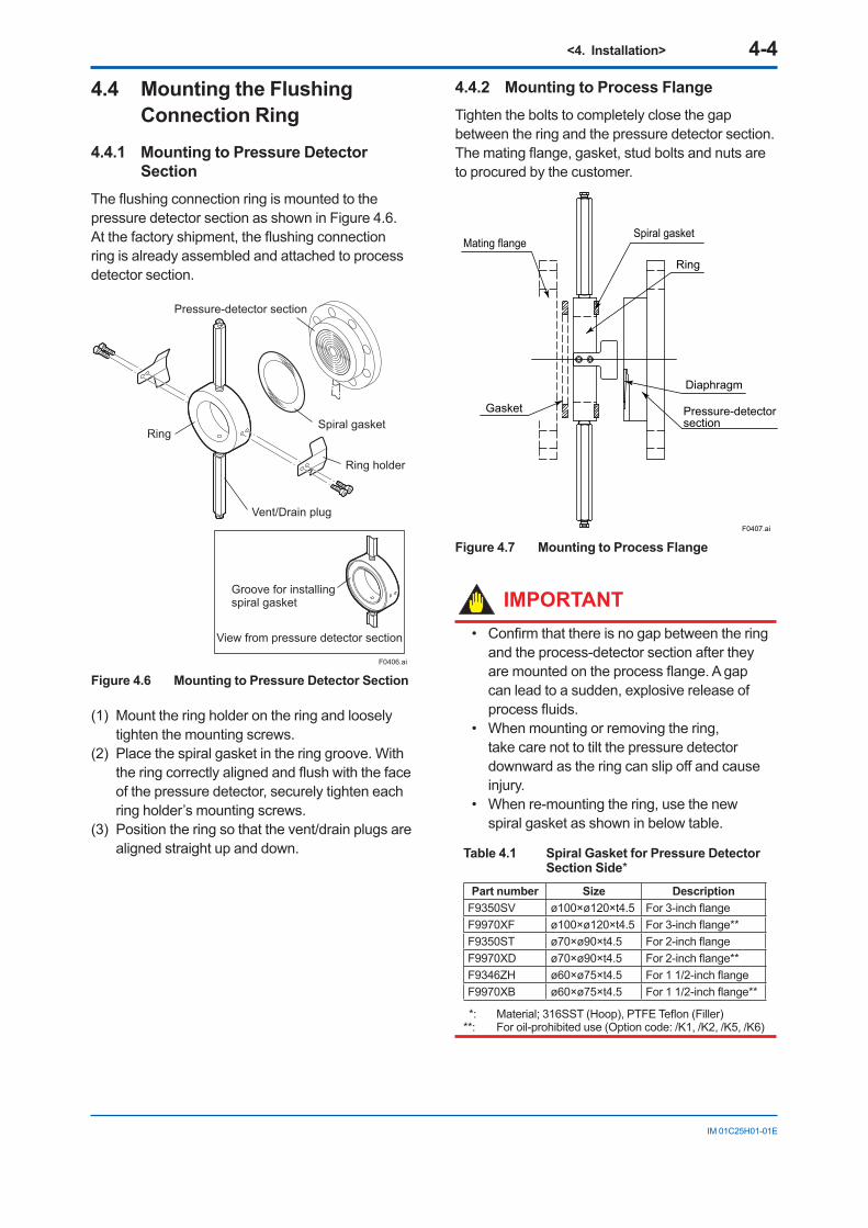
4.4 Mounting the Flushing Connection Ring
4.4.1 Mounting to Pressure Detector Section
Theflushingconnectionringismountedtothepressure detector section as shown in Figure 4.6. Atthefactoryshipment,theflushingconnectionring is already assembled and attached to process detector section.
Ring holder
Spiral gasket
F0406.ai
View from pressure detector section
Groove for installingspiral gasket
Pressure-detector section
Vent/Drain plug
Ring
Figure 4.6 Mounting to Pressure Detector Section
(1) Mount the ring holder on the ring and loosely tighten the mounting screws.
(2) Place the spiral gasket in the ring groove. With theringcorrectlyalignedandflushwiththefaceof the pressure detector, securely tighten each ring holder’s mounting screws.
(3) Position the ring so that the vent/drain plugs are aligned straight up and down.
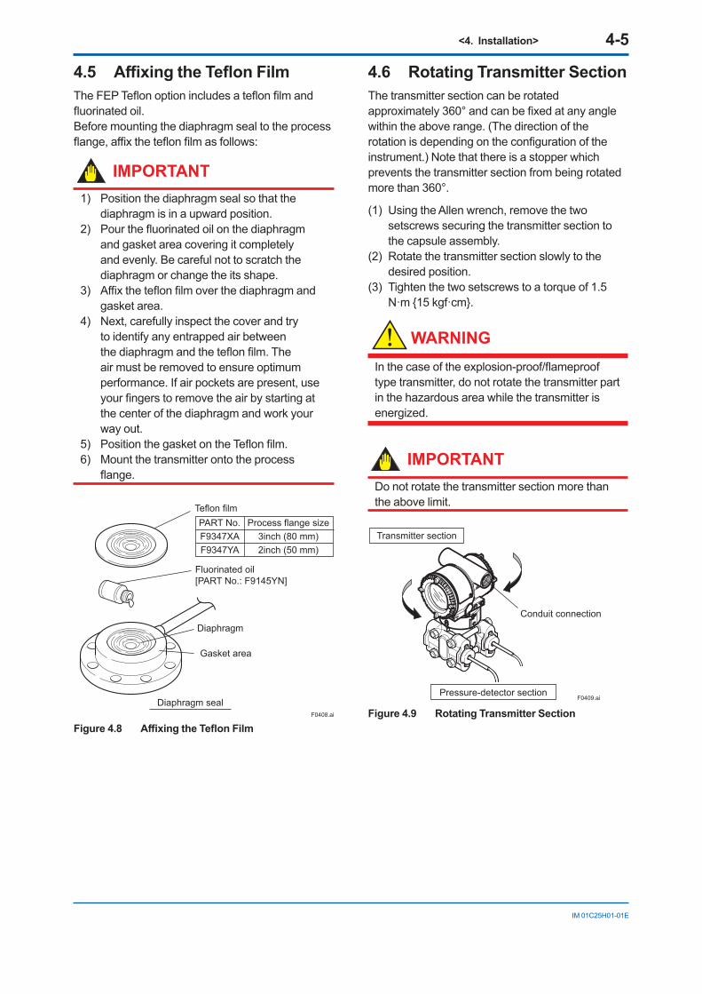
4.4.2 Mounting to Process FlangeTighten the bolts to completely close the gap between the ring and the pressure detector section.Thematingflange,gasket,studboltsandnutsareto procured by the customer.
F0407.ai
Ring
Diaphragm
Pressure-detector section
Gasket
Mating flangeSpiral gasket
Figure 4.7 Mounting to Process Flange
IMPORTANT• Confirmthatthereisnogapbetweenthering
and the process-detector section after they aremountedontheprocessflange.Agapcan lead to a sudden, explosive release of processfluids.
• When mounting or removing the ring, take care not to tilt the pressure detector downwardastheringcanslipoffandcauseinjury.
• When re-mounting the ring, use the new spiral gasket as shown in below table.
Table 4.1 Spiral Gasket for Pressure Detector Section Side*
Part number Size DescriptionF9350SV ø100×ø120×t4.5 For3-inchflangeF9970XF ø100×ø120×t4.5 For3-inchflange**F9350ST ø70×ø90×t4.5 For2-inchflangeF9970XD ø70×ø90×t4.5 For2-inchflange**F9346ZH ø60×ø75×t4.5 For11/2-inchflangeF9970XB ø60×ø75×t4.5 For11/2-inchflange**
*: Material;316SST(Hoop),PTFETeflon(Filler)**: For oil-prohibited use (Option code: /K1, /K2, /K5, /K6)
<4. Installation> 4-5
IM 01C25H01-01E
4.5 Affixing the Teflon FilmTheFEPTeflonoptionincludesateflonfilmandfluorinatedoil.Before mounting the diaphragm seal to the process flange,affixtheteflonfilmasfollows:
IMPORTANT1) Position the diaphragm seal so that the
diaphragm is in a upward position.2) Pourthefluorinatedoilonthediaphragm
and gasket area covering it completely and evenly. Be careful not to scratch the diaphragm or change the its shape.
3) Affixtheteflonfilmoverthediaphragmandgasket area.
4) Next, carefully inspect the cover and try to identify any entrapped air between thediaphragmandtheteflonfilm.Theair must be removed to ensure optimum performance. If air pockets are present, use yourfingerstoremovetheairbystartingatthe center of the diaphragm and work your way out.
5) PositionthegasketontheTeflonfilm.6) Mount the transmitter onto the process
flange.
Teflon film
Diaphragm
Fluorinated oil[PART No.: F9145YN]
Gasket area
Diaphragm seal
PART No.F9347XAF9347YA
Process flange size3inch (80 mm)2inch (50 mm)
F0408.ai
Figure 4.8 Affixing the Teflon Film
4.6 Rotating Transmitter SectionThe transmitter section can be rotated approximately360°andcanbefixedatanyanglewithin the above range. (The direction of the rotationisdependingontheconfigurationoftheinstrument.) Note that there is a stopper which prevents the transmitter section from being rotated more than 360°.
(1) Using the Allen wrench, remove the two setscrews securing the transmitter section to the capsule assembly.
(2) Rotate the transmitter section slowly to the desired position.
(3) Tighten the two setscrews to a torque of 1.5 N·m 15 kgf·cm.
WARNING
Inthecaseoftheexplosion-proof/flameprooftype transmitter, do not rotate the transmitter part in the hazardous area while the transmitter is energized.
IMPORTANTDo not rotate the transmitter section more thanthe above limit.
F0409.ai
Transmitter section
Pressure-detector section
Conduit connection
Figure 4.9 Rotating Transmitter Section
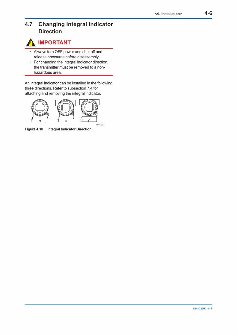
<4. Installation> 4-6
IM 01C25H01-01E
4.7 Changing Integral Indicator Direction
IMPORTANT• AlwaysturnOFFpowerandshutoffand
release pressures before disassembly. • For changing the integral indicator direction,
the transmitter must be removed to a non-hazardous area.
An integral indicator can be installed in the following three directions, Refer to subsection 7.4 for attaching and removing the integral indicator.
F0410.ai
Figure 4.10 Integral Indicator Direction
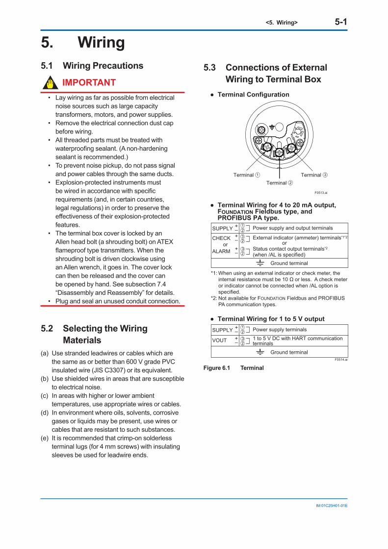
<5. Wiring> 5-1
IM 01C25H01-01E
5. Wiring5.1 Wiring Precautions
IMPORTANT• Lay wiring as far as possible from electrical
noise sources such as large capacity transformers, motors, and power supplies.
• Remove the electrical connection dust cap before wiring.
• All threaded parts must be treated with waterproofingsealant.(Anon-hardeningsealant is recommended.)
• To prevent noise pickup, do not pass signal and power cables through the same ducts.
• Explosion-protected instruments must bewiredinaccordancewithspecificrequirements (and, in certain countries, legal regulations) in order to preserve the effectivenessoftheirexplosion-protectedfeatures.
• The terminal box cover is locked by an Allen head bolt (a shrouding bolt) on ATEX flameprooftypetransmitters.Whentheshrouding bolt is driven clockwise using an Allen wrench, it goes in. The cover lock can then be released and the cover can be opened by hand. See subsection 7.4 “Disassembly and Reassembly” for details.
• Plug and seal an unused conduit connection.
5.2 Selecting the Wiring Materials
(a) Use stranded leadwires or cables which are the same as or better than 600 V grade PVC insulated wire (JIS C3307) or its equivalent.
(b) Use shielded wires in areas that are susceptible to electrical noise.
(c) In areas with higher or lower ambient temperatures, use appropriate wires or cables.
(d) In environment where oils, solvents, corrosive gases or liquids may be present, use wires or cables that are resistant to such substances.
(e) It is recommended that crimp-on solderless terminal lugs (for 4 mm screws) with insulating sleeves be used for leadwire ends.
5.3 Connections of External Wiring to Terminal Box
F0513.ai
Terminal Configuration
1Terminal 2Terminal
3Terminal
Power supply and output terminals
External indicator (ammeter) terminals*1*2
orStatus contact output terminals*2
(when /AL is specified)
Terminal Wiring for 4 to 20 mA output, FOUNDATION Fieldbus type, and PROFIBUS PA type.
SUPPLY
CHECKor
ALARM
+–+– +–
Ground terminal
12
2
2
3
3
F0514.ai
SUPPLY
VOUT
+–+–
Terminal Wiring for 1 to 5 V output
Ground terminal
Power supply terminals
1 to 5 V DC with HART communication terminals
12
23
*1: When using an external indicator or check meter, the internal resistance must be 10 Ω or less. A check meter or indicator cannot be connected when /AL option is specified.
*2: Not available for FOUNDATION Fieldbus and PROFIBUS PA communication types.
Figure 6.1 Terminal
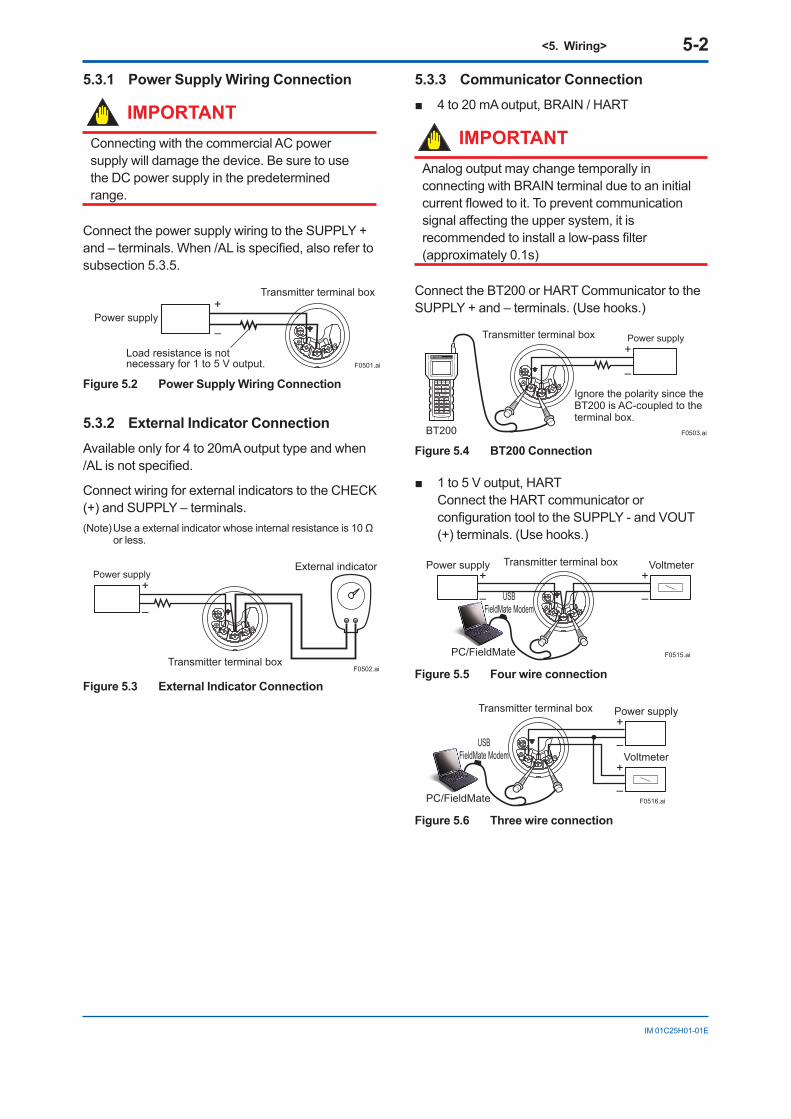
<5. Wiring> 5-2
IM 01C25H01-01E
5.3.1 Power Supply Wiring Connection
IMPORTANTConnecting with the commercial AC power supply will damage the device. Be sure to use the DC power supply in the predetermined range.
Connect the power supply wiring to the SUPPLY + and–terminals.When/ALisspecified,alsorefertosubsection 5.3.5.
Power supply–
+Transmitter terminal box
F0501.ai
Load resistance is not necessary for 1 to 5 V output.
Figure 5.2 Power Supply Wiring Connection
5.3.2 External Indicator ConnectionAvailable only for 4 to 20mA output type and when /ALisnotspecified.
Connect wiring for external indicators to the CHECK (+) and SUPPLY – terminals.(Note)Useaexternalindicatorwhoseinternalresistanceis10Ω
or less.
Transmitter terminal box
External indicator
F0502.ai
Power supply
–
+
Figure 5.3 External Indicator Connection
5.3.3 Communicator Connection 4to20mAoutput,BRAIN/HART
IMPORTANTAnalog output may change temporally in connecting with BRAIN terminal due to an initial currentflowedtoit.Topreventcommunicationsignalaffectingtheuppersystem,itisrecommendedtoinstallalow-passfilter(approximately 0.1s)
Connect the BT200 or HART Communicator to the SUPPLY + and – terminals. (Use hooks.)
Transmitter terminal box
BT200 F0503.ai
Power supply
–
+
Ignore the polarity since the BT200 is AC-coupled to the terminal box.
Figure 5.4 BT200 Connection
1to5Voutput,HARTConnect the HART communicator or configurationtooltotheSUPPLY-andVOUT(+) terminals. (Use hooks.)
Transmitter terminal box
F0515.ai
Voltmeter
–
+Power supply
–
+
USBFieldMate Modem
PC/FieldMate
Figure 5.5 Four wire connection
Transmitter terminal box
F0516.ai
Power supply
–
+
Voltmeter
–
+
USBFieldMate Modem
PC/FieldMate
Figure 5.6 Three wire connection
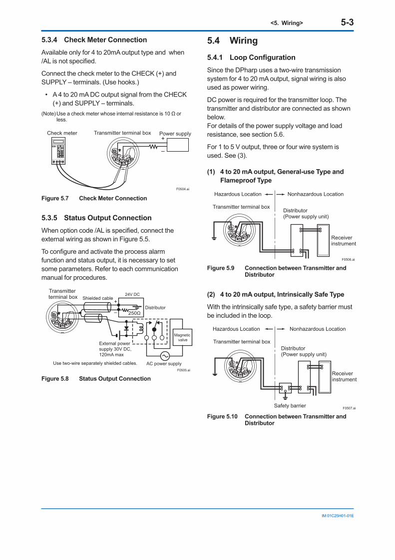
<5. Wiring> 5-3
IM 01C25H01-01E
5.3.4 Check Meter ConnectionAvailable only for 4 to 20mA output type and when /ALisnotspecified.
Connect the check meter to the CHECK (+) and SUPPLY – terminals. (Use hooks.)
• A 4 to 20 mA DC output signal from the CHECK (+) and SUPPLY – terminals.
(Note)Useacheckmeterwhoseinternalresistanceis10Ωorless.
Transmitter terminal box
F0504.ai
Power supply
–
+Check meter
Figure 5.7 Check Meter Connection
5.3.5 Status Output ConnectionWhenoptioncode/ALisspecified,connecttheexternal wiring as shown in Figure 5.5.
Toconfigureandactivatetheprocessalarmfunction and status output, it is necessary to set some parameters. Refer to each communication manual for procedures.
Transmitter terminal box
Magnetic valve
AC power supply
External power supply 30V DC, 120mA max
+
– 250Ω
24V DC
Use two-wire separately shielded cables.
Distributor
Shielded cable
F0505.ai
Figure 5.8 Status Output Connection
5.4 Wiring5.4.1 Loop ConfigurationSince the DPharp uses a two-wire transmission system for 4 to 20 mA output, signal wiring is also used as power wiring.
DC power is required for the transmitter loop. The transmitter and distributor are connected as shown below.For details of the power supply voltage and load resistance, see section 5.6.
For 1 to 5 V output, three or four wire system is used. See (3).
(1) 4 to 20 mA output, General-use Type and Flameproof Type
Hazardous Location Nonhazardous Location
Transmitter terminal boxDistributor (Power supply unit)
Receiver instrument
F0506.ai
Figure 5.9 Connection between Transmitter and Distributor
(2) 4 to 20 mA output, Intrinsically Safe Type
With the intrinsically safe type, a safety barrier must be included in the loop.
Hazardous Location Nonhazardous Location
Transmitter terminal boxDistributor (Power supply unit)
Receiver instrument
Safety barrier F0507.ai
Figure 5.10 Connection between Transmitter and Distributor
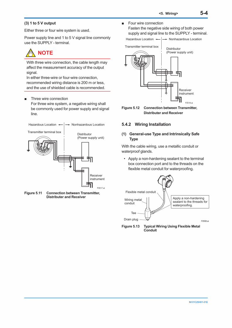
<5. Wiring> 5-4
IM 01C25H01-01E
(3) 1 to 5 V output
Either three or four wire system is used.
Power supply line and 1 to 5 V signal line commonly use the SUPPLY - terminal.
NOTEWith three wire connection, the cable length may affectthemeasurementaccuracyoftheoutputsignal. In either three-wire or four-wire connection, recommended wiring distance is 200 m or less, and the use of shielded cable is recommended.
ThreewireconnectionFor three wire system, a negative wiring shall be commonly used for power supply and signal line.
F0517.ai
Hazardous Location Nonhazardous Location
Transmitter terminal boxDistributor (Power supply unit)
Receiver instrument
Figure 5.11 Connection between Transmitter, Distributer and Receiver
FourwireconnectionFasten the negative side wiring of both power supply and signal line to the SUPPLY - terminal.
Hazardous Location Nonhazardous Location
Transmitter terminal boxDistributor (Power supply unit)
Receiver instrument
F0518.ai
Figure 5.12 Connection between Transmitter, Distributer and Receiver
5.4.2 Wiring Installation
(1) General-use Type and Intrinsically Safe Type
With the cable wiring, use a metallic conduit or waterproof glands.
• Apply a non-hardening sealant to the terminal box connection port and to the threads on the flexiblemetalconduitforwaterproofing.
F0508.ai
Flexible metal conduit
Wiring metalconduit
Tee
Drain plug
Apply a non-hardeningsealant to the threads forwaterproofing.
Figure 5.13 Typical Wiring Using Flexible Metal Conduit
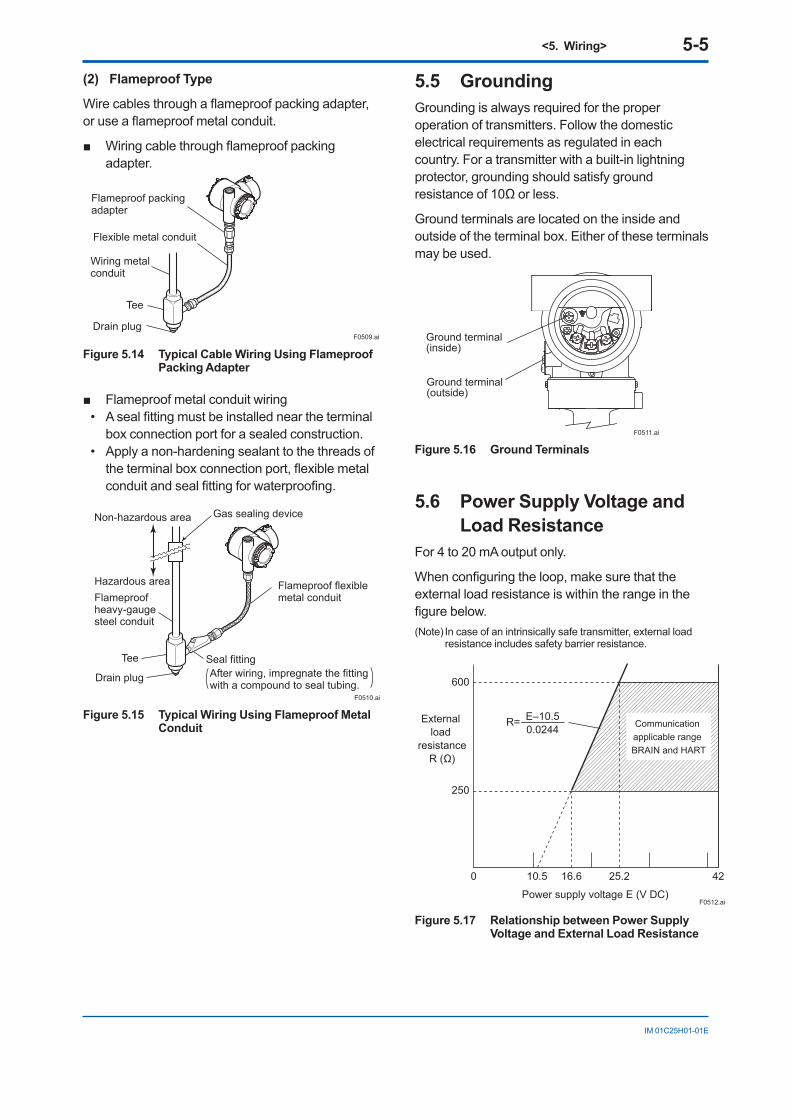
<5. Wiring> 5-5
IM 01C25H01-01E
(2) Flameproof Type
Wirecablesthroughaflameproofpackingadapter,oruseaflameproofmetalconduit.
Wiringcablethroughflameproofpackingadapter.
Flameproof packing adapter
Flexible metal conduit
Wiring metalconduit
Tee
Drain plugF0509.ai
Figure 5.14 Typical Cable Wiring Using Flameproof Packing Adapter
Flameproof metal conduit wiring• Asealfittingmustbeinstalledneartheterminal
box connection port for a sealed construction.• Apply a non-hardening sealant to the threads of theterminalboxconnectionport,flexiblemetalconduitandsealfittingforwaterproofing.
F0510.ai
Non-hazardous area
Hazardous areaFlameproofheavy-gaugesteel conduit
Tee
Drain plug
Seal fitting
Gas sealing device
Flameproof flexiblemetal conduit
After wiring, impregnate the fittingwith a compound to seal tubing.
Figure 5.15 Typical Wiring Using Flameproof Metal Conduit
5.5 GroundingGrounding is always required for the proper operation of transmitters. Follow the domestic electrical requirements as regulated in each country. For a transmitter with a built-in lightning protector, grounding should satisfy ground resistanceof10Ωorless.
Ground terminals are located on the inside and outside of the terminal box. Either of these terminals may be used.
Ground terminal(inside)
Ground terminal(outside)
F0511.ai
Figure 5.16 Ground Terminals
5.6 Power Supply Voltage and Load Resistance
For 4 to 20 mA output only.
Whenconfiguringtheloop,makesurethattheexternal load resistance is within the range in the figurebelow.(Note) In case of an intrinsically safe transmitter, external load
resistance includes safety barrier resistance.
600
250
0 10.5 16.6 25.2 42
External load
resistanceR (Ω)
Power supply voltage E (V DC)F0512.ai
Communication applicable range BRAIN and HART
R= E–10.50.0244
Figure 5.17 Relationship between Power Supply Voltage and External Load Resistance
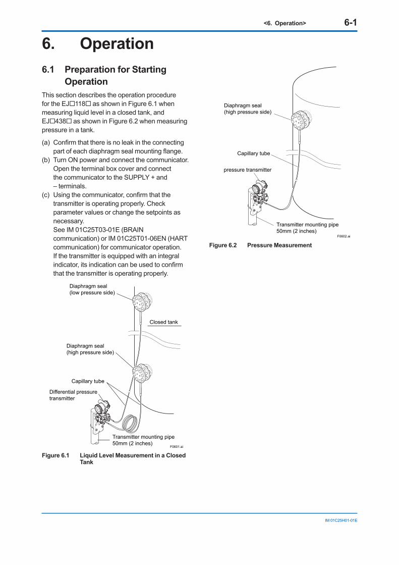
<6. Operation> 6-1
IM 01C25H01-01E
6. Operation6.1 Preparation for Starting
OperationThis section describes the operation procedure for the EJ118 as shown in Figure 6.1 when measuring liquid level in a closed tank, and EJ438 as shown in Figure 6.2 when measuring pressure in a tank.
(a) Confirmthatthereisnoleakintheconnectingpartofeachdiaphragmsealmountingflange.
(b) Turn ON power and connect the communicator. Open the terminal box cover and connect
the communicator to the SUPPLY + and – terminals.
(c) Usingthecommunicator,confirmthatthetransmitter is operating properly. Check parameter values or change the setpoints as necessary.
See IM 01C25T03-01E (BRAIN communication) or IM 01C25T01-06EN (HART communication) for communicator operation. If the transmitter is equipped with an integral indicator,itsindicationcanbeusedtoconfirmthat the transmitter is operating properly.
F0601.ai
Closed tank
Transmitter mounting pipe50mm (2 inches)
Capillary tube
Differential pressuretransmitter
Diaphragm seal(high pressure side)
Diaphragm seal(low pressure side)
Figure 6.1 Liquid Level Measurement in a Closed Tank
F0602.ai
Transmitter mounting pipe50mm (2 inches)
Capillary tube
pressure transmitter
Diaphragm seal(high pressure side)
Figure 6.2 Pressure Measurement
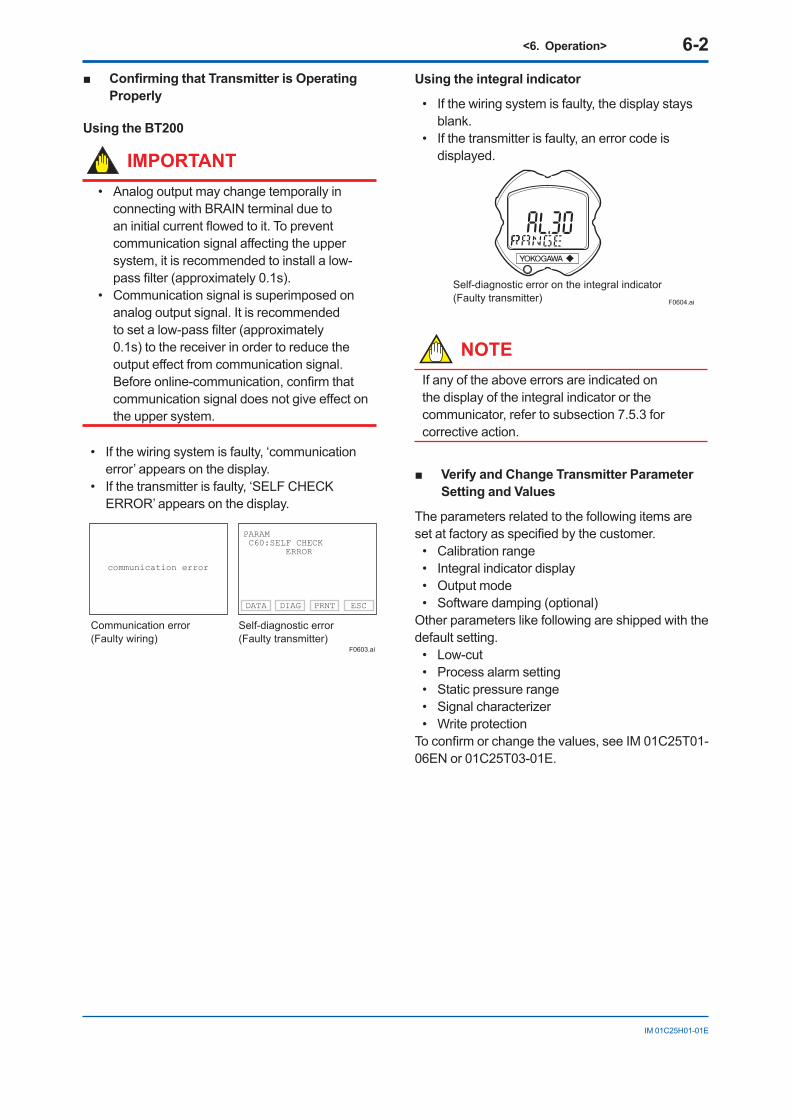
<6. Operation> 6-2
IM 01C25H01-01E
Confirming that Transmitter is Operating Properly
Using the BT200
IMPORTANT• Analog output may change temporally in
connecting with BRAIN terminal due to aninitialcurrentflowedtoit.Topreventcommunicationsignalaffectingtheuppersystem, it is recommended to install a low-passfilter(approximately0.1s).
• Communication signal is superimposed on analog output signal. It is recommended tosetalow-passfilter(approximately0.1s) to the receiver in order to reduce the outputeffectfromcommunicationsignal.Beforeonline-communication,confirmthatcommunicationsignaldoesnotgiveeffectonthe upper system.
• If the wiring system is faulty, ‘communication error’ appears on the display.
• If the transmitter is faulty, ‘SELF CHECK ERROR’ appears on the display.
communication error
PARAM C60:SELF CHECK ERROR
Communication error (Faulty wiring)
Self-diagnostic error(Faulty transmitter)
DATA DIAG PRNT ESC
F0603.ai
Using the integral indicator
• If the wiring system is faulty, the display stays blank.
• If the transmitter is faulty, an error code is displayed.
Self-diagnostic error on the integral indicator(Faulty transmitter) F0604.ai
NOTEIf any of the above errors are indicated on the display of the integral indicator or the communicator, refer to subsection 7.5.3 for corrective action.
Verify and Change Transmitter Parameter Setting and Values
The parameters related to the following items are setatfactoryasspecifiedbythecustomer.
• Calibration range• Integral indicator display• Output mode• Software damping (optional)
Other parameters like following are shipped with the default setting.
• Low-cut• Process alarm setting• Static pressure range• Signal characterizer• Write protection Toconfirmorchangethevalues,seeIM01C25T01-06EN or 01C25T03-01E.
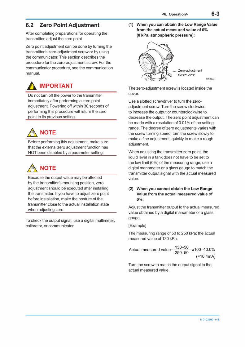
<6. Operation> 6-3
IM 01C25H01-01E
6.2 Zero Point AdjustmentAfter completing preparations for operating the transmitter, adjust the zero point.
Zero point adjustment can be done by turning the transmitter’s zero-adjustment screw or by using the communicator. This section describes the procedure for the zero-adjustment screw. For the communicator procedure, see the communication manual.
IMPORTANTDonotturnoffthepowertothetransmitterimmediately after performing a zero point adjustment.Poweringoffwithin30secondsofperforming this procedure will return the zero point to its previous setting.
NOTEBefore performing this adjustment, make sure that the external zero adjustment function has NOT been disabled by a parameter setting.
NOTEBecausetheoutputvaluemaybeaffectedby the transmitter’s mounting position, zero adjustment should be executed after installing the transmitter. If you have to adjust zero point before installation, make the posture of the transmitter close to the actual installation state when adjusting zero.
To check the output signal, use a digital multimeter, calibrator, or communicator.
(1) When you can obtain the Low Range Value from the actual measured value of 0% (0 kPa, atmospheric pressure);
Zero-adjustmentscrew cover
F0605.ai
The zero-adjustment screw is located inside the cover.
Use a slotted screwdriver to turn the zero-adjustment screw. Turn the screw clockwise to increase the output or counterclockwise to decrease the output. The zero point adjustment can be made with a resolution of 0.01% of the setting range. The degree of zero adjustments varies with the screw turning speed; turn the screw slowly to makeafineadjustment,quicklytomakearoughadjustment.
When adjusting the transmitter zero point, the liquid level in a tank does not have to be set to the low limit (0%) of the measuring range; use a digital manometer or a glass gauge to match the transmitter output signal with the actual measured value.
(2) When you cannot obtain the Low Range Value from the actual measured value of 0%;
Adjust the transmitter output to the actual measured value obtained by a digital manometer or a glass gauge.
[Example]
The measuring range of 50 to 250 kPa; the actual measured value of 130 kPa.
130–50250–50
Actual measured value= x100=40.0%(=10.4mA)
Turn the screw to match the output signal to the actual measured value.
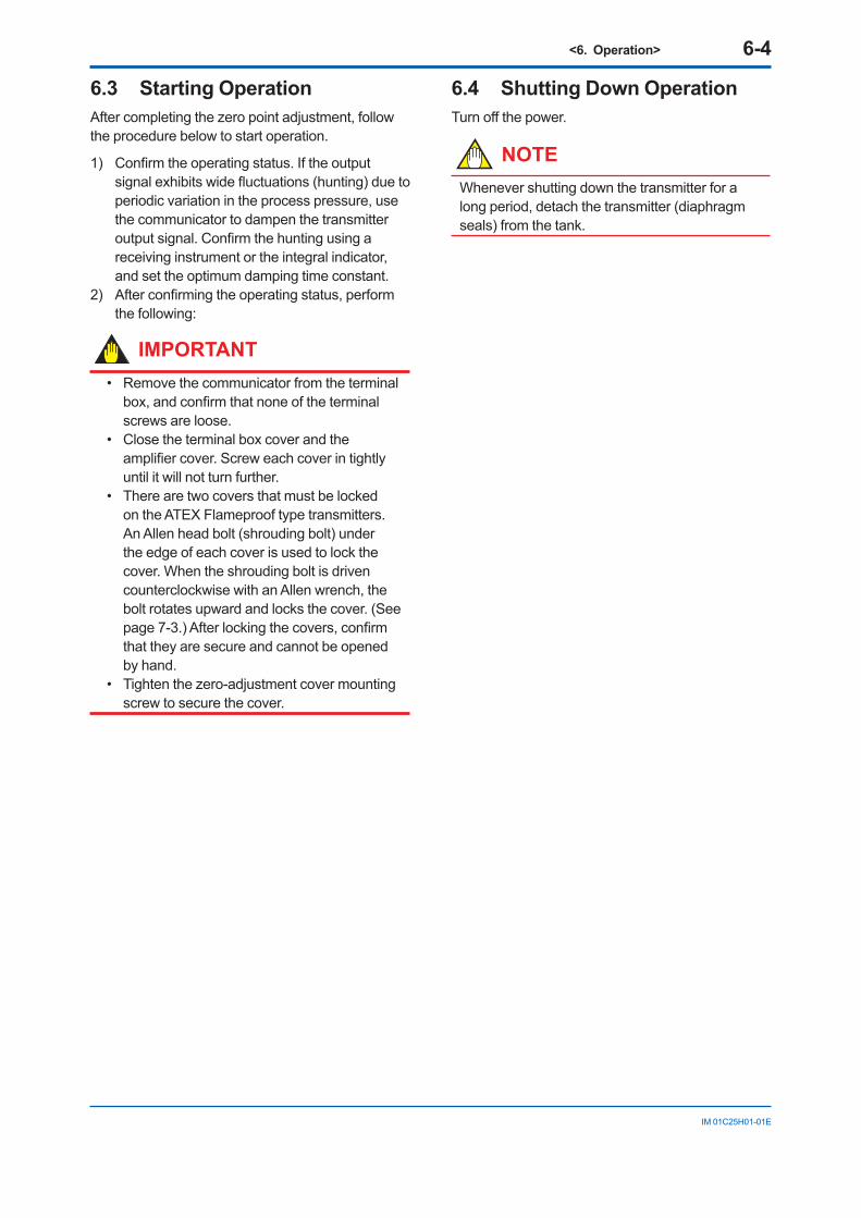
<6. Operation> 6-4
IM 01C25H01-01E
6.3 Starting OperationAfter completing the zero point adjustment, follow the procedure below to start operation.
1) Confirmtheoperatingstatus.Iftheoutputsignalexhibitswidefluctuations(hunting)duetoperiodic variation in the process pressure, use the communicator to dampen the transmitter outputsignal.Confirmthehuntingusingareceiving instrument or the integral indicator, and set the optimum damping time constant.
2) Afterconfirmingtheoperatingstatus,performthe following:
IMPORTANT• Remove the communicator from the terminal box,andconfirmthatnoneoftheterminalscrews are loose.
• Close the terminal box cover and the amplifiercover.Screweachcoverintightlyuntil it will not turn further.
• There are two covers that must be locked on the ATEX Flameproof type transmitters. An Allen head bolt (shrouding bolt) under the edge of each cover is used to lock the cover. When the shrouding bolt is driven counterclockwise with an Allen wrench, the bolt rotates upward and locks the cover. (See page7-3.)Afterlockingthecovers,confirmthat they are secure and cannot be opened by hand.
• Tighten the zero-adjustment cover mounting screw to secure the cover.
6.4 Shutting Down OperationTurnoffthepower.
NOTEWhenever shutting down the transmitter for a long period, detach the transmitter (diaphragm seals) from the tank.
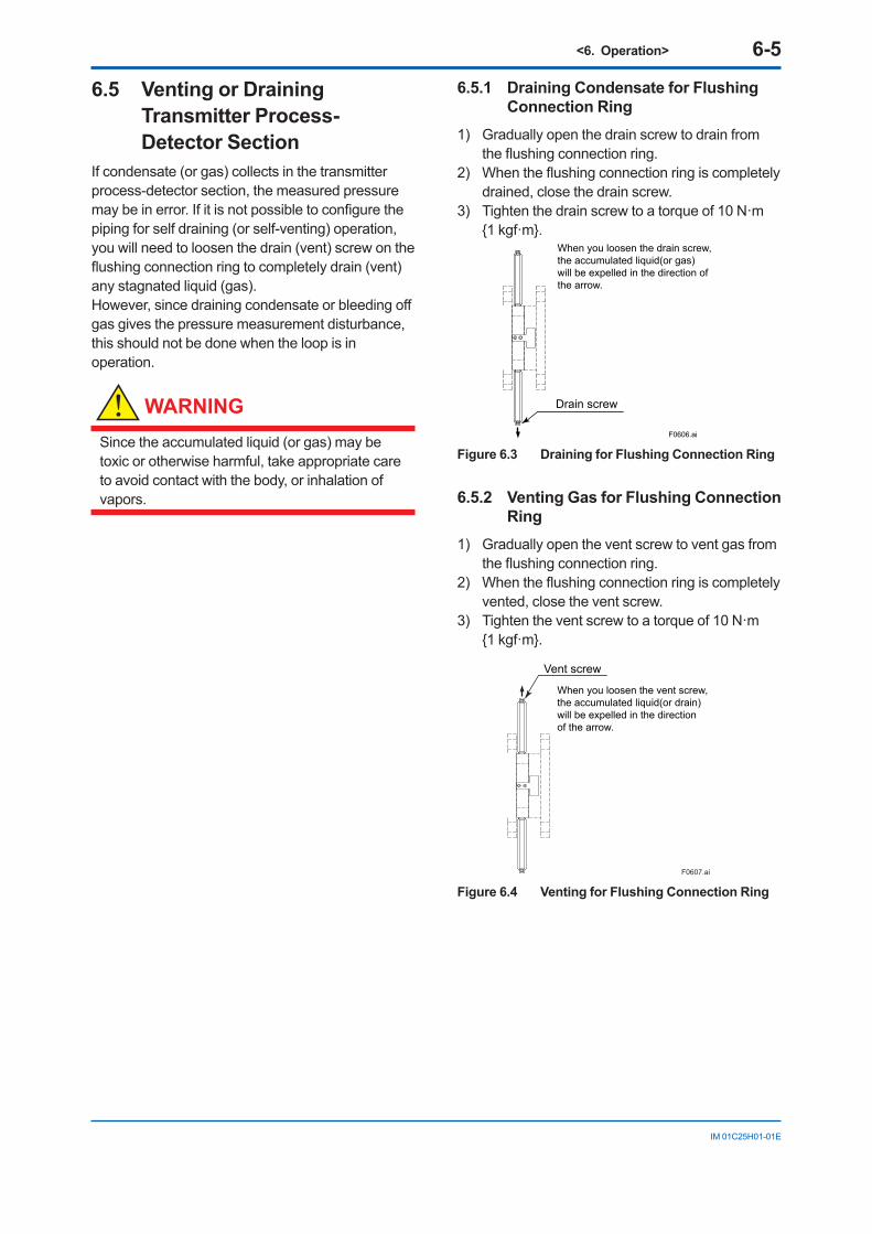
<6. Operation> 6-5
IM 01C25H01-01E
6.5 Venting or Draining Transmitter Process-Detector Section
If condensate (or gas) collects in the transmitter process-detector section, the measured pressure maybeinerror.Ifitisnotpossibletoconfigurethepiping for self draining (or self-venting) operation, you will need to loosen the drain (vent) screw on the flushingconnectionringtocompletelydrain(vent)any stagnated liquid (gas).However,sincedrainingcondensateorbleedingoffgas gives the pressure measurement disturbance, this should not be done when the loop is in operation.
WARNING
Since the accumulated liquid (or gas) may be toxic or otherwise harmful, take appropriate care to avoid contact with the body, or inhalation of vapors.
6.5.1 Draining Condensate for Flushing Connection Ring
1) Gradually open the drain screw to drain from theflushingconnectionring.
2) Whentheflushingconnectionringiscompletelydrained, close the drain screw.
3) Tighten the drain screw to a torque of 10 N·m 1 kgf·m.
F0606.ai
Drain screw
When you loosen the drain screw, the accumulated liquid(or gas) will be expelled in the direction of the arrow.
Figure 6.3 Draining for Flushing Connection Ring
6.5.2 Venting Gas for Flushing Connection Ring
1) Gradually open the vent screw to vent gas from theflushingconnectionring.
2) Whentheflushingconnectionringiscompletelyvented, close the vent screw.
3) Tighten the vent screw to a torque of 10 N·m 1 kgf·m.
F0607.ai
Vent screw
When you loosen the vent screw, the accumulated liquid(or drain) will be expelled in the direction of the arrow.
Figure 6.4 Venting for Flushing Connection Ring
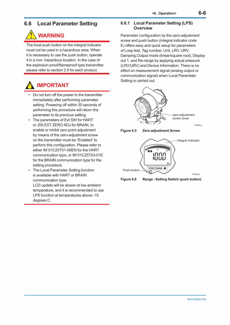
<6. Operation> 6-6
IM 01C25H01-01E
6.6 Local Parameter Setting
WARNING
The local push button on the integral indicator must not be used in a hazardous area. When it is necessary to use the push button, operate it in a non- hazardous location. In the case of theexplosion-proof/flameprooftypetransmitter,please refer to section 2.9 for each product.
IMPORTANT• Donotturnoffthepowertothetransmitter
immediately after performing parameter setting.Poweringoffwithin30secondsofperforming this procedure will return the parameter to its previous setting.
• The parameters of Ext SW for HART or J55:EXT ZERO ADJ for BRAIN, to enable or inhibit zero point adjustment by means of the zero-adjustment screw on the transmitter must be “Enabled” to performthisconfiguration.Pleaserefertoeither IM 01C25T01-06EN for the HART communication type, or IM 01C25T03-01E for the BRAIN communication type for the setting procedure.
• The Local Parameter Setting function is available with HART or BRAIN communication type.LCD update will be slower at low ambient temperature, and it is recommended to use LPS function at temperatures above -10 degrees C.
6.6.1 Local Parameter Setting (LPS) Overview
Parameterconfigurationbythezero-adjustmentscrew and push button (integral indicator code E)offerseasyandquicksetupforparametersof Loop test, Tag number, Unit, LRV, URV, Damping,Output mode (linear/square root), Display out 1, and Re-range by applying actual pressure (LRV/URV) and Device Information. There is no effectonmeasurementsignal(analogoutputorcommunication signal) when Local Parameter Setting is carried out.
zero-adjustment screw cover
F0608.ai
Figure 6.5 Zero-adjustment Screw
F0609.ai
Integral indicator
Push-button
Figure 6.6 Range –Setting Switch (push button)
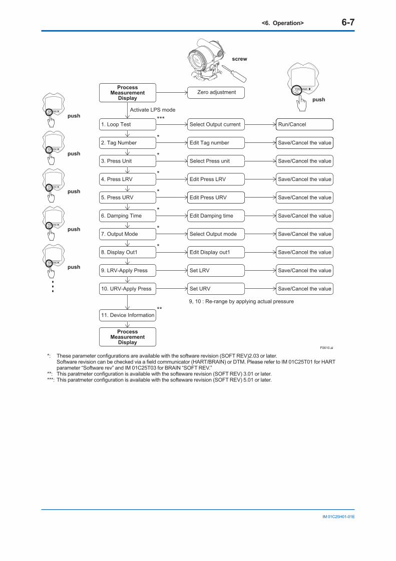
<6. Operation> 6-7
IM 01C25H01-01E
F0610.ai
screw
push
push
push
push
push
push
Save/Cancel the value
Save/Cancel the value
Save/Cancel the value
Save/Cancel the value
Save/Cancel the value
Save/Cancel the value
Save/Cancel the value
Save/Cancel the value
Save/Cancel the value
7. Output Mode
3. Press Unit
2. Tag Number*
*
*
*
*
*
*
4. Press LRV
5. Press URV
8. Display Out1
9. LRV-Apply Press
10. URV-Apply Press
6. Damping Time
Select Output mode
Select Press unit
Edit Tag number
Edit Press LRV
Edit Press URV
Edit Display Out1
Set LRV
Set URV
Edit Damping time
ProcessMeasurement
Display Zero adjustment
9, 10 : Re-range by applying actual pressure
ProcessMeasurement
Display
11. Device Information
Run/Cancel1. Loop Test***
Select Output Current
Activate LPS mode
**
*: Theseparameterconfigurationsareavailablewiththesoftwarerevision(SOFTREV)2.03orlater. Softwarerevisioncanbecheckedviaafieldcommunicator(HART/BRAIN)orDTM.PleaserefertoIM01C25T01forHARTparameter “Software rev” and IM 01C25T03 for BRAIN “SOFT REV.”
**: Thisparatmeterconfigurationisavailablewiththesoftewarerevision(SOFTREV)3.01orlater.***:Thisparatmeterconfigurationisavailablewiththesoftewarerevision(SOFTREV)5.01orlater.
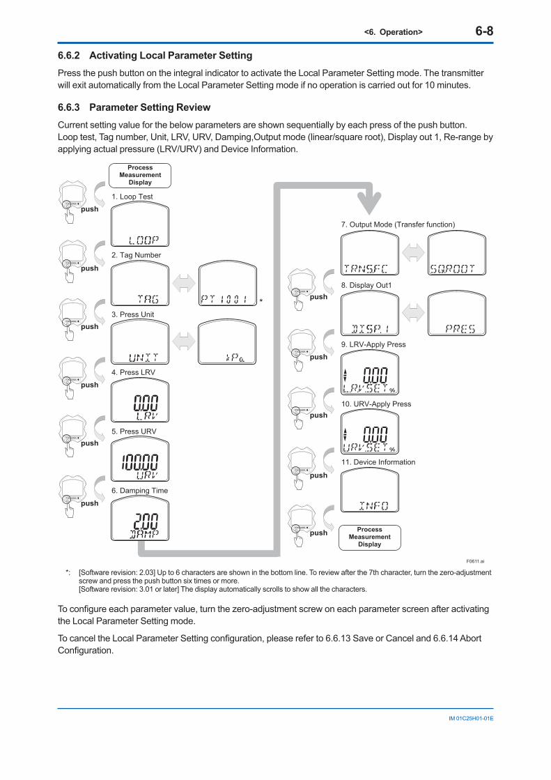
<6. Operation> 6-8
IM 01C25H01-01E
6.6.2 Activating Local Parameter SettingPress the push button on the integral indicator to activate the Local Parameter Setting mode. The transmitter will exit automatically from the Local Parameter Setting mode if no operation is carried out for 10 minutes.
6.6.3 Parameter Setting ReviewCurrent setting value for the below parameters are shown sequentially by each press of the push button.Loop test, Tag number, Unit, LRV, URV, Damping,Output mode (linear/square root), Display out 1, Re-range by applying actual pressure (LRV/URV) and Device Information.
F0611.ai
push
push
push
push
push
push
push
push
push ProcessMeasurement
Display
*
push
push
ProcessMeasurement
Display
1. Loop Test
2. Tag Number
3. Press Unit
4. Press LRV
5. Press URV
6. Damping Time
7. Output Mode (Transfer function)
8. Display Out1
9. LRV-Apply Press
10. URV-Apply Press
11. Device Information
*: [Software revision: 2.03] Up to 6 characters are shown in the bottom line. To review after the 7th character, turn the zero-adjustment screw and press the push button six times or more. [Software revision: 3.01 or later] The display automatically scrolls to show all the characters.
Toconfigureeachparametervalue,turnthezero-adjustmentscrewoneachparameterscreenafteractivatingthe Local Parameter Setting mode.
TocanceltheLocalParameterSettingconfiguration,pleasereferto6.6.13SaveorCanceland6.6.14AbortConfiguration.
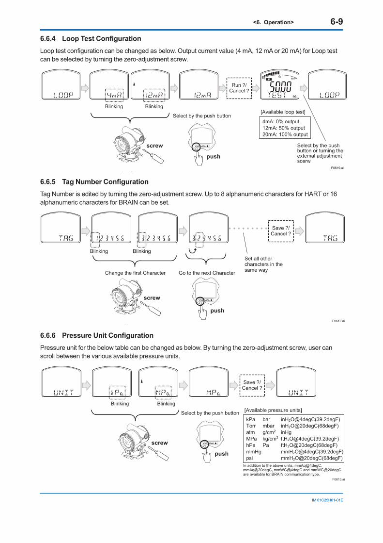
<6. Operation> 6-9
IM 01C25H01-01E
6.6.4 Loop Test ConfigurationLooptestconfigurationcanbechangedasbelow.Outputcurrentvalue(4mA,12mAor20mA)forLooptestcan be selected by turning the zero-adjustment screw.
[Available loop test]
4mA: 0% output12mA: 50% output20mA: 100% output
Select by the push button or turning the extemal adjustment scerw
F0619.ai
screw
push
Select by the push button
Blinking Blinking
Run ?/Cancel ?
6.6.5 Tag Number ConfigurationTag Number is edited by turning the zero-adjustment screw. Up to 8 alphanumeric characters for HART or 16 alphanumeric characters for BRAIN can be set.
F0612.ai
screw
push
Change the first Character Go to the next Character
Set all other characters in the same way
Blinking Blinking
Save ?/Cancel ?
6.6.6 Pressure Unit ConfigurationPressure unit for the below table can be changed as below. By turning the zero-adjustment screw, user can scroll between the various available pressure units.
F0613.ai
screw
push
Select by the push button
Blinking Blinking
Save ?/Cancel ?
[Available pressure units]
kPa bar inH2O@4degC(39.2degF)Torr mbar inH2O@20degC(68degF)atm g/cm2 inHgMPa kg/cm2 ftH2O@4degC(39.2degF)hPa Pa ftH2O@20degC(68degF)mmHg mmH2O@4degC(39.2degF)psi mmH2O@20degC(68degF)
In addition to the above units, mmAq@4degC, mmAq@20degC, mmWG@4degC and mmWG@20degC are available for BRAIN communication type.
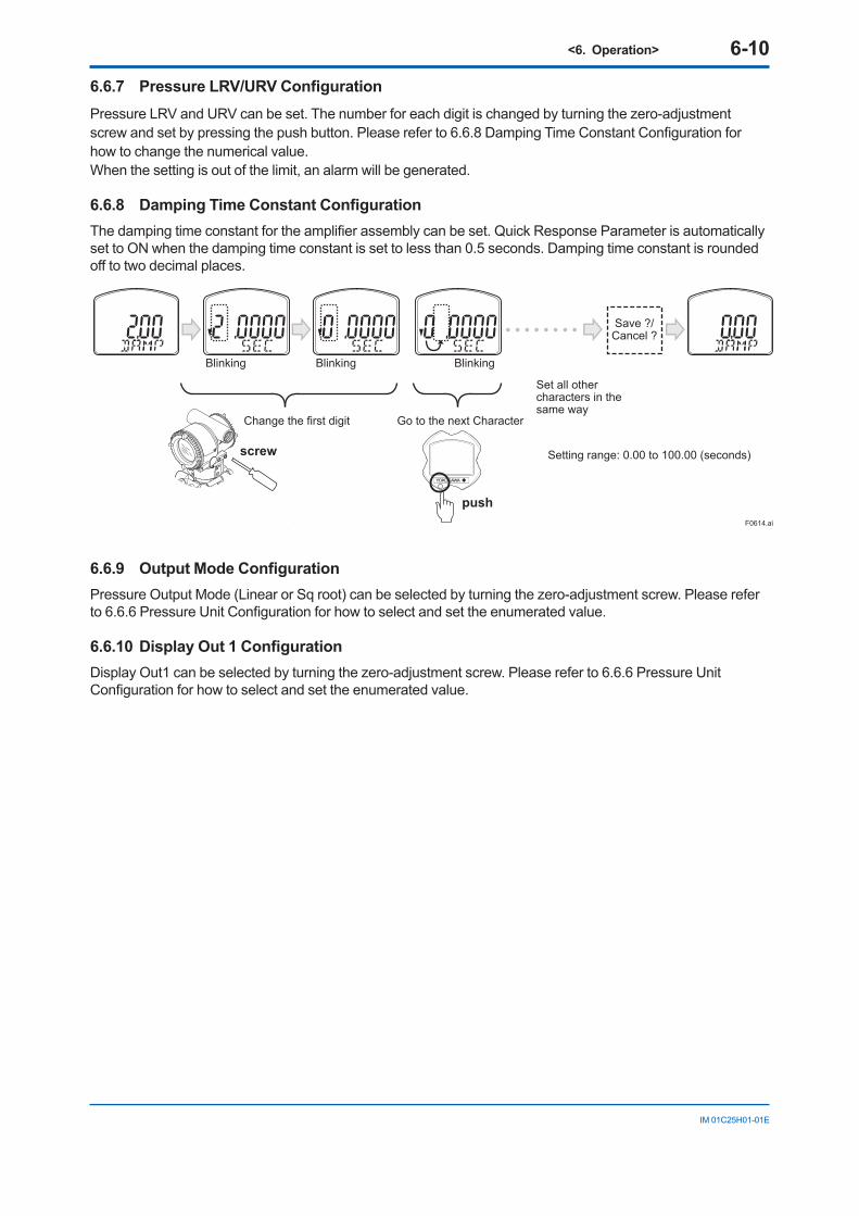
<6. Operation> 6-10
IM 01C25H01-01E
6.6.7 Pressure LRV/URV ConfigurationPressure LRV and URV can be set. The number for each digit is changed by turning the zero-adjustment screwandsetbypressingthepushbutton.Pleasereferto6.6.8DampingTimeConstantConfigurationforhow to change the numerical value. When the setting is out of the limit, an alarm will be generated.
6.6.8 Damping Time Constant ConfigurationThedampingtimeconstantfortheamplifierassemblycanbeset.QuickResponseParameterisautomaticallyset to ON when the damping time constant is set to less than 0.5 seconds. Damping time constant is rounded offtotwodecimalplaces.
F0614.ai
screw
Change the first digit
Set all other characters in the same way
Setting range: 0.00 to 100.00 (seconds)
Blinking Blinking Blinking
Save ?/Cancel ?
push
Go to the next Character
6.6.9 Output Mode ConfigurationPressure Output Mode (Linear or Sq root) can be selected by turning the zero-adjustment screw. Please refer to6.6.6PressureUnitConfigurationforhowtoselectandsettheenumeratedvalue.
6.6.10 Display Out 1 ConfigurationDisplay Out1 can be selected by turning the zero-adjustment screw. Please refer to 6.6.6 Pressure Unit Configurationforhowtoselectandsettheenumeratedvalue.
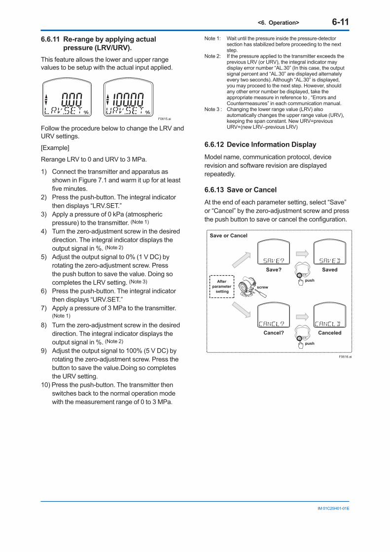
<6. Operation> 6-11
IM 01C25H01-01E
6.6.11 Re-range by applying actual pressure (LRV/URV).
This feature allows the lower and upper range values to be setup with the actual input applied.
F0615.ai
Follow the procedure below to change the LRV and URV settings.
[Example]
Rerange LRV to 0 and URV to 3 MPa.
1) Connect the transmitter and apparatus as shown in Figure 7.1 and warm it up for at least fiveminutes.
2) Press the push-button. The integral indicator then displays “LRV.SET.”
3) Apply a pressure of 0 kPa (atmospheric pressure) to the transmitter. (Note 1)
4) Turn the zero-adjustment screw in the desired direction. The integral indicator displays the output signal in %. (Note 2)
5) Adjust the output signal to 0% (1 V DC) by rotating the zero-adjustment screw. Press the push button to save the value. Doing so completes the LRV setting. (Note 3)
6) Press the push-button. The integral indicator then displays “URV.SET.”
7) Apply a pressure of 3 MPa to the transmitter. (Note 1)
8) Turn the zero-adjustment screw in the desired direction. The integral indicator displays the output signal in %. (Note 2)
9) Adjust the output signal to 100% (5 V DC) by rotating the zero-adjustment screw. Press the button to save the value.Doing so completes the URV setting.
10) Press the push-button. The transmitter then switches back to the normal operation mode with the measurement range of 0 to 3 MPa.
Note 1: Wait until the pressure inside the pressure-detector section has stabilized before proceeding to the next step.
Note 2: If the pressure applied to the transmitter exceeds the previous LRV (or URV), the integral indicator may display error number “AL.30” (In this case, the output signal percent and “AL.30” are displayed alternately every two seconds). Although “AL.30” is displayed, you may proceed to the next step. However, should any other error number be displayed, take the appropriate measure in reference to , “Errors and Countermeasures” in each communication manual.
Note 3 : Changing the lower range value (LRV) also automatically changes the upper range value (URV), keeping the span constant. New URV=previous URV+(new LRV–previous LRV)
6.6.12 Device Information DisplayModel name, communication protocol, device revision and software revision are displayed repeatedly.
6.6.13 Save or CancelAt the end of each parameter setting, select “Save” or “Cancel” by the zero-adjustment screw and press thepushbuttontosaveorcanceltheconfiguration.
Save? Saved
Save or Cancel
Cancel? Canceled
screw
F0616.ai
push
push
After parameter
setting
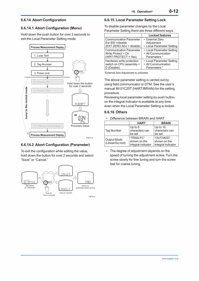
<6. Operation> 6-12
IM 01C25H01-01E
6.6.14 Abort Configuration
6.6.14.1 Abort Configuration (Menu)Hold down the push button for over 2 seconds to exit the Local Parameter Setting mode.
Hold down the button for over 2 seconds
Proccess Value
Process Measurement Display
Process Measurement Display
1. Loop Test
2. Tag Number
3. Press Unit
4. Press LRV
5. Press URV
11. Device Information
F0617.ai
Jum
p to
the
norm
al m
ode
:
:
6.6.14.2 Abort Configuration (Parameter)Toexittheconfigurationwhileeditingthevalue,hold down the button for over 2 seconds and select “Save” or “Cancel.”
F0618.ai
Return to parameter review window
Save or Cancel?Push for Over 2 seconds
Tag editing (3rd Character)
6.6.15 Local Parameter Setting LockTo disable parameter changes by the Local ParameterSettingtherearethreedifferentways.
Locked featuresCommunication ParameterExt SW =disable(EXT ZERO ADJ = disable)
• External Zero Adjustment
• Local Parameter SettingCommunication ParameterWrite Protect = On(WRT PROTECT = Yes)
• Local Parameter Setting• All Communication
Parameters *Hardware write protection switch on CPU assembly = D (Disable)
• Local Parameter Setting • All Communication
Parameters **External Zero Adjustment is unlocked.
The above parameter setting is carried out by usingfieldcommunicatororDTM.Seetheuser’smanual IM 01C25T (HART/BRAIN) for the setting procedure.Reviewing local parameter setting by push button on the integral indicator is available at any time even when the Local Parameter Setting is locked.
6.6.16 Others• DifferencebetweenBRAINandHART
HART BRAIN
Tag NumberUp to 8 characters can be set
Up to 16 characters can be set
Output Mode (Linear/Sq root)
“TRNS.FC” shown on the integral indicator
“OUT.MOD” shown on the integral indicator
• The degree of adjustment depends on the speed of turning the adjustment screw. Turn the screwslowlyforfinetuningandturnthescrewfast for coarse tuning.
<7. Maintenance> 7-1
IM 01C25H01-01E
7. Maintenance7.1 Overview
WARNING
Sincetheaccumulatedprocessfluidmaybetoxic or otherwise harmful, take appropriate care to avoid contact with the body or inhalation of vapors when draining condensate or venting gas from the transmitter pressure-detector section and even after dismounting the instrument from the process line for maintenance.
Maintenance of the transmitter is easy due to its modular construction. This chapter describes the procedures for calibration, adjustment, and the disassembly and reassembly procedures required for component replacement.
Transmitters are precision instruments. Please carefully and thoroughly read the following sections for information on how to properly handle them while performing maintenance.
IMPORTANT• As a rule, maintenance of this transmitter
should be done in a shop that has all the necessary tools.
• The CPU assembly contains sensitive parts that can be damaged by static electricity. Take precautions such as using a grounded wrist strap when handling electronic parts or touching the board circuit patterns. Also be sure to place the removed CPU assembly into a bag with an antistatic coating.
7.2 Calibration Instruments Selection
Table 7.1 lists the instruments that can be used to calibrate a transmitter. When selecting an instrument, consider the required accuracy level. Exercise care when handling these instruments to ensuretheymaintainthespecifiedaccuracy.
7.3 CalibrationUse the procedure below to check instrument operation and accuracy during periodic maintenance or troubleshooting.
1) Connecttheinstrumentsasshowninfigure7.1andwarmuptheinstrumentsforatleastfiveminutes.
IMPORTANT• To adjust the transmitter for highest
accuracy, make adjustments with the power supply voltage and load resistance including leadwire resistances set close to the conditions under which the transmitter is installed. In addition, place the process connections of both high and low pressure side on the same level.
• If the measurement range 0% point is 0 kPa or shifted in the positive direction (suppressed zero), the reference pressure shouldbeappliedasshowninthefigure. If the measurement range 0% point is shifted in the negative direction (elevated zero), the reference pressure should be applied using a vacuum pump.
2) Apply reference pressures of 0%, 50%, and 100% of the measurement range to the transmitter.Calculatetheerrors(differencesbetween digital voltmeter readings and reference pressures) as the pressure is increased from 0% to 100% and is decreased from100%to0%,andconfirmthattheerrorsare within the required accuracy.
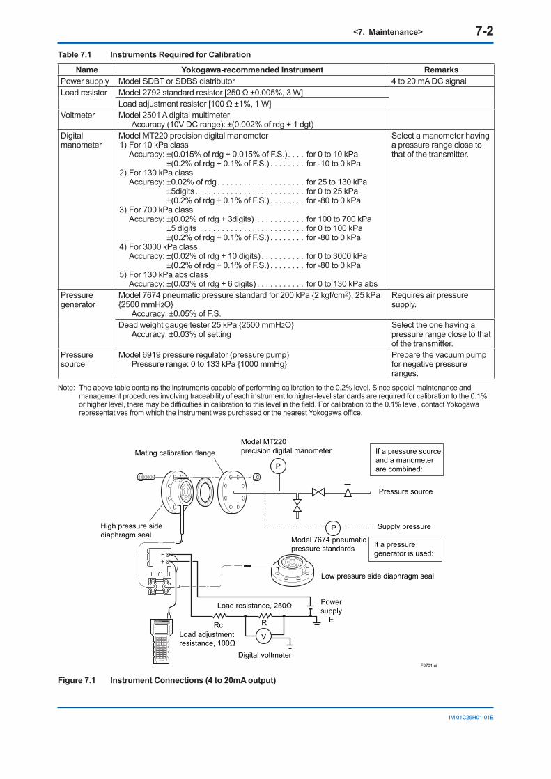
<7. Maintenance> 7-2
IM 01C25H01-01E
Table 7.1 Instruments Required for Calibration
Name Yokogawa-recommended Instrument RemarksPower supply Model SDBT or SDBS distributor 4 to 20 mA DC signalLoad resistor Model2792standardresistor[250Ω±0.005%,3W]
Loadadjustmentresistor[100Ω±1%,1W]Voltmeter Model 2501 A digital multimeter
Accuracy(10VDCrange):±(0.002%ofrdg+1dgt)Digital manometer
Model MT220 precision digital manometer1) For 10 kPa class Accuracy:±(0.015%ofrdg+0.015%ofF.S.). . . . for 0 to 10 kPa ±(0.2%ofrdg+0.1%ofF.S.) . . . . . . . . for -10 to 0 kPa2) For 130 kPa class Accuracy:±0.02%ofrdg . . . . . . . . . . . . . . . . . . . . for 25 to 130 kPa ±5digits . . . . . . . . . . . . . . . . . . . . . . . . . for 0 to 25 kPa ±(0.2%ofrdg+0.1%ofF.S.) . . . . . . . . for -80 to 0 kPa3) For 700 kPa class Accuracy:±(0.02%ofrdg+3digits) . . . . . . . . . . . for 100 to 700 kPa ±5digits . . . . . . . . . . . . . . . . . . . . . . . . for 0 to 100 kPa ±(0.2%ofrdg+0.1%ofF.S.) . . . . . . . . for -80 to 0 kPa4) For 3000 kPa class Accuracy:±(0.02%ofrdg+10digits) . . . . . . . . . . for 0 to 3000 kPa ±(0.2%ofrdg+0.1%ofF.S.) . . . . . . . . for -80 to 0 kPa5) For 130 kPa abs class Accuracy:±(0.03%ofrdg+6digits) . . . . . . . . . . . for 0 to 130 kPa abs
Select a manometer having a pressure range close to that of the transmitter.
Pressure generator
Model 7674 pneumatic pressure standard for 200 kPa 2 kgf/cm2, 25 kPa 2500 mmH2O
Accuracy:±0.05%ofF.S.
Requires air pressure supply.
Dead weight gauge tester 25 kPa 2500 mmH2OAccuracy:±0.03%ofsetting
Select the one having a pressure range close to that of the transmitter.
Pressure source
Model 6919 pressure regulator (pressure pump)Pressure range: 0 to 133 kPa 1000 mmHg
Prepare the vacuum pump for negative pressure ranges.
Note: The above table contains the instruments capable of performing calibration to the 0.2% level. Since special maintenance and management procedures involving traceability of each instrument to higher-level standards are required for calibration to the 0.1% orhigherlevel,theremaybedifficultiesincalibrationtothislevelinthefield.Forcalibrationtothe0.1%level,contactYokogawarepresentativesfromwhichtheinstrumentwaspurchasedorthenearestYokogawaoffice.
P
P
V
Mating calibration flange
Load resistance, 250Ω
Model MT220precision digital manometer
High pressure sidediaphragm seal
Rc RLoad adjustmentresistance, 100Ω
Digital voltmeter
Powersupply
E
Low pressure side diaphragm seal
Model 7674 pneumaticpressure standards
Pressure source
Supply pressure
If a pressuregenerator is used:
If a pressure sourceand a manometerare combined:
F0701.ai
Figure 7.1 Instrument Connections (4 to 20mA output)
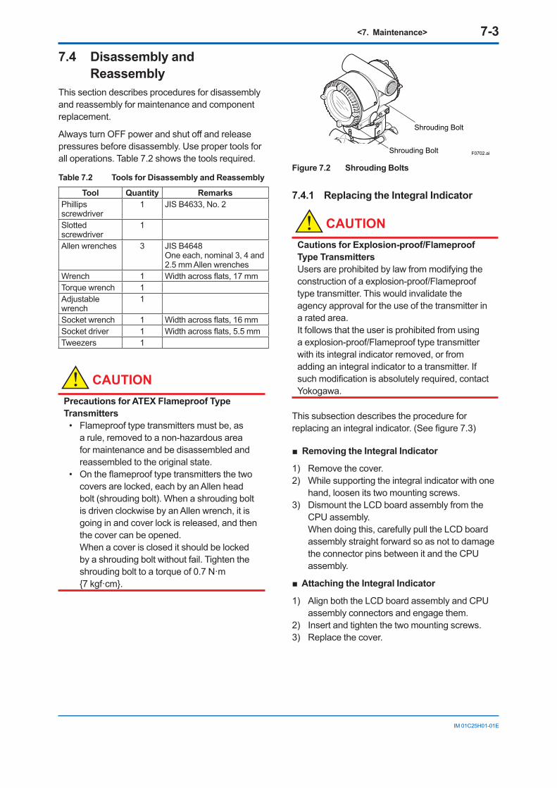
<7. Maintenance> 7-3
IM 01C25H01-01E
7.4 Disassembly and Reassembly
This section describes procedures for disassembly and reassembly for maintenance and component replacement.
AlwaysturnOFFpowerandshutoffandreleasepressures before disassembly. Use proper tools for all operations. Table 7.2 shows the tools required.
Table 7.2 Tools for Disassembly and Reassembly
Tool Quantity RemarksPhillips screwdriver
1 JIS B4633, No. 2
Slotted screwdriver
1
Allen wrenches 3 JIS B4648 One each, nominal 3, 4 and 2.5 mm Allen wrenches
Wrench 1 Widthacrossflats,17mmTorque wrench 1Adjustable wrench
1
Socket wrench 1 Widthacrossflats,16mmSocket driver 1 Widthacrossflats,5.5mmTweezers 1
CAUTIONPrecautions for ATEX Flameproof Type Transmitters
• Flameproof type transmitters must be, as a rule, removed to a non-hazardous area for maintenance and be disassembled and reassembled to the original state.
• Ontheflameprooftypetransmittersthetwocovers are locked, each by an Allen head bolt (shrouding bolt). When a shrouding bolt is driven clockwise by an Allen wrench, it is going in and cover lock is released, and then the cover can be opened.
When a cover is closed it should be locked by a shrouding bolt without fail. Tighten the shrouding bolt to a torque of 0.7 N·m 7 kgf·cm.
Shrouding Bolt
Shrouding Bolt F0702.ai
Figure 7.2 Shrouding Bolts
7.4.1 Replacing the Integral Indicator
CAUTIONCautions for Explosion-proof/Flameproof Type TransmittersUsers are prohibited by law from modifying the construction of a explosion-proof/Flameproof type transmitter. This would invalidate the agency approval for the use of the transmitter in a rated area. It follows that the user is prohibited from using a explosion-proof/Flameproof type transmitter with its integral indicator removed, or from adding an integral indicator to a transmitter. If suchmodificationisabsolutelyrequired,contactYokogawa.
This subsection describes the procedure for replacinganintegralindicator.(Seefigure7.3)
Removing the Integral Indicator
1) Remove the cover.2) While supporting the integral indicator with one
hand, loosen its two mounting screws.3) Dismount the LCD board assembly from the
CPU assembly. When doing this, carefully pull the LCD board
assembly straight forward so as not to damage the connector pins between it and the CPU assembly.
Attaching the Integral Indicator
1) Align both the LCD board assembly and CPU assembly connectors and engage them.
2) Insert and tighten the two mounting screws.3) Replace the cover.
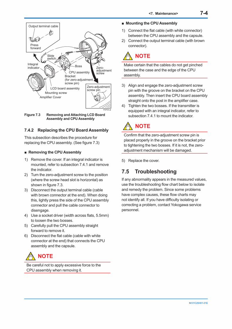
<7. Maintenance> 7-4
IM 01C25H01-01E
F0703.ai
Pressforward
Output terminal cable
Zero-adjustmentscrew pin
Slide switch
Boss Zero-adjustmentscrew
Integralindicator
Mounting screwAmplifier Cover
CPU assemblyBracket(for zero-adjustmentscrew pin)
LCD board assembly
Figure 7.3 Removing and Attaching LCD Board Assembly and CPU Assembly
7.4.2 Replacing the CPU Board AssemblyThis subsection describes the procedure for replacingtheCPUassembly.(Seefigure7.3)
Removing the CPU Assembly
1) Remove the cover. If an integral indicator is mounted, refer to subsection 7.4.1 and remove the indicator.
2) Turn the zero-adjustment screw to the position (where the screw head slot is horizontal) as showninfigure7.3.
3) Disconnect the output terminal cable (cable with brown connector at the end). When doing this, lightly press the side of the CPU assembly connector and pull the cable connector to disengage.
4) Useasocketdriver(widthacrossflats,5.5mm)to loosen the two bosses.
5) Carefully pull the CPU assembly straight forward to remove it.
6) Disconnecttheflatcable(cablewithwhiteconnector at the end) that connects the CPU assembly and the capsule.
NOTEBe careful not to apply excessive force to the CPU assembly when removing it.
Mounting the CPU Assembly
1) Connecttheflatcable(withwhiteconnector)between the CPU assembly and the capsule.
2) Connect the output terminal cable (with brown connector).
NOTEMake certain that the cables do not get pinched between the case and the edge of the CPU assembly.
3) Align and engage the zero-adjustment screw pin with the groove on the bracket on the CPU assembly. Then insert the CPU board assembly straightontothepostintheamplifiercase.
4) Tighten the two bosses. If the transmitter is equipped with an integral indicator, refer to subsection 7.4.1 to mount the indicator.
NOTEConfirmthatthezero-adjustmentscrewpinisplaced properly in the groove on the bracket prior to tightening the two bosses. If it is not, the zero-adjustment mechanism will be damaged.
5) Replace the cover.
7.5 TroubleshootingIf any abnormality appears in the measured values, usethetroubleshootingflowchartbelowtoisolateand remedy the problem. Since some problems havecomplexcauses,theseflowchartsmaynotidentifyall.Ifyouhavedifficultyisolatingorcorrecting a problem, contact Yokogawa service personnel.
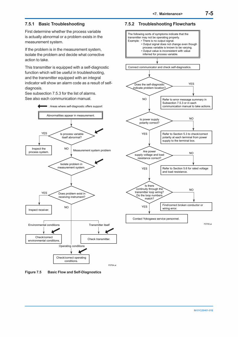
<7. Maintenance> 7-5
IM 01C25H01-01E
7.5.1 Basic TroubleshootingFirst determine whether the process variable is actually abnormal or a problem exists in the measurement system.
If the problem is in the measurement system, isolate the problem and decide what corrective action to take.
This transmitter is equipped with a self-diagnostic function which will be useful in troubleshooting, and the transmitter equipped with an integral indicator will show an alarm code as a result of self-diagnosis. See subsection 7.5.3 for the list of alarms. See also each communication manual.
Abnormalities appear in measurement.
: Areas where self-diagnostic offers support
Is process variableitself abnormal?
Inspect theprocess system.
Isolate problem inmeasurement system.
Does problem exist inreceiving instrument?
Check/correctenvironmental conditions.
Inspect receiver.
Check transmitter.
Check/correct operatingconditions.
Measurement system problem
F0704.ai
YES
NO
NO
YES
Environmental conditions
Operating conditions
Transmitter itself
Figure 7.5 Basic Flow and Self-Diagnostics
7.5.2 Troubleshooting Flowcharts
Connect communicator and check self-diagnostics.
Does the self-diagnosticindicate problem location?
Contact Yokogawa service personnel.
F0705.ai
The following sorts of symptoms indicate that the transmitter may not be operating properly.Example : • There is no output signal. • Output signal does not change even though process variable is known to be varying. • Output value is inconsistent with value inferred for process variable.
Is power supplypolarity correct?
Are powersupply voltage and load
resistance correct?
Refer to Section 5.3 to check/correctpolarity at each terminal from powersupply to the terminal box.
Refer to Section 5.6 for rated voltage and load resistance.
Find/correct broken conductor or wiring error.
Is therecontinuity through the
transmitter loop wiring?Do the loop numbers
match?
YES
NO
NO
YES
NO
YES
NO
YES
Refer to error message summary in Subsection 7.5.3 or in each communication manual to take actions.
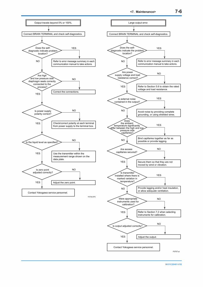
<7. Maintenance> 7-6
IM 01C25H01-01E
Connect BRAIN TERMINAL and check self-diagnostics.
Does the self-diagnostic indicate problem
location?
Contact Yokogawa service personnel.F0706.EPS
Is power supplypolarity correct?
Are high and low pressure side
diaphragm seals correctly connected to the
process?
Refer to error message summary in eachcommunication manual to take actions.
YES
NO
NO
YES Check/correct polarity at each terminal from power supply to the terminal box.
Use the transmitter within the measurement range shown on the data plate.
Correct the connections.
NO
YES
YES
Adjust the zero point.
NO
NO
YES
Is the liquid level as specified?
Is zero point adjusted correctly?
Output travels beyond 0% or 100%.
Connect BRAIN TERMINAL and check self-diagnostics.
Contact Yokogawa service personnel.
F0707.ai
Are power supply voltage and load
resistance correct?
Is external noise contained in the output?
Refer to error message summary in each communication manual to take actions.
Bind capillaries together as far as possible or provide lagging.
Provide lagging and/or heat insulation, or allow adequate ventilation.
Refer to Section 7.2 when selectinginstruments for calibration.
Refer to Section 5.6 to obtain the ratedvoltage and load resistance.
Avoid noise by providing complete grounding, or using shielded wires.
Adjust the output.
Does the ambient
temperature significantly differ between the high and low
pressure sidecapillaries?
Is output adjusted correctly?
Large output error.
Does the self-diagnostic indicate the problem
location?
Is transmitterinstalled where there is
marked variation in temperature?
Are excess capillaries secured?
YES
NO
YES
NO
NO
YES
NO
YES
NO
YES
NO
YES
NO
YES
Secure them so that they are notmoved by wind or vibration.
Were appropriate instruments used for
calibration?
YES
NO
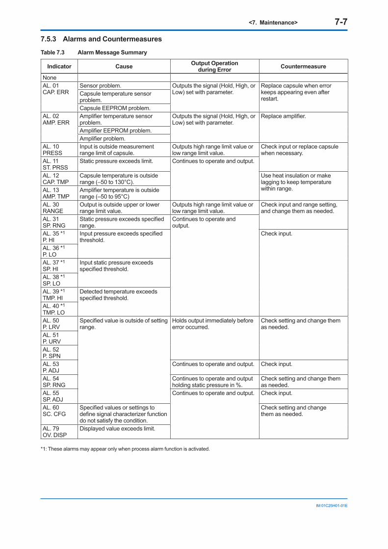
<7. Maintenance> 7-7
IM 01C25H01-01E
7.5.3 Alarms and Countermeasures
Table 7.3 Alarm Message Summary
Indicator Cause Output Operationduring Error Countermeasure
NoneAL. 01CAP. ERR
Sensor problem. Outputs the signal (Hold, High, or Low) set with parameter.
Replace capsule when error keeps appearing even after restart.
Capsule temperature sensor problem.Capsule EEPROM problem.
AL. 02AMP. ERR
Amplifiertemperaturesensorproblem.
Outputs the signal (Hold, High, or Low) set with parameter.
Replaceamplifier.
AmplifierEEPROMproblem.Amplifierproblem.
AL. 10PRESS
Input is outside measurement range limit of capsule.
Outputs high range limit value or low range limit value.
Check input or replace capsule when necessary.
AL. 11ST. PRSS
Static pressure exceeds limit. Continues to operate and output.
AL. 12CAP. TMP
Capsule temperature is outside range (–50 to 130°C).
Use heat insulation or make lagging to keep temperature within range.AL. 13
AMP. TMPAmplifiertemperatureisoutsiderange (–50 to 95°C)
AL. 30RANGE
Output is outside upper or lower range limit value.
Outputs high range limit value or low range limit value.
Check input and range setting, and change them as needed.
AL. 31SP. RNG
Staticpressureexceedsspecifiedrange.
Continues to operate andoutput.
AL. 35 *1
P. HIInputpressureexceedsspecifiedthreshold.
Check input.
AL. 36 *1
P. LOAL. 37 *1
SP. HIInput static pressure exceeds specifiedthreshold.
AL. 38 *1
SP. LOAL. 39 *1
TMP. HIDetected temperature exceeds specifiedthreshold.
AL. 40 *1
TMP. LOAL. 50P. LRV
Specifiedvalueisoutsideofsettingrange.
Holds output immediately before error occurred.
Check setting and change them as needed.
AL. 51P. URVAL. 52P. SPNAL. 53P. ADJ
Continues to operate and output. Check input.
AL. 54SP. RNG
Continues to operate and output holding static pressure in %.
Check setting and change them as needed.
AL. 55SP. ADJ
Continues to operate and output. Check input.
AL. 60SC. CFG
Specifiedvaluesorsettingstodefinesignalcharacterizerfunctiondo not satisfy the condition.
Check setting and changethem as needed.
AL. 79OV. DISP
Displayed value exceeds limit.
*1: These alarms may appear only when process alarm function is activated.
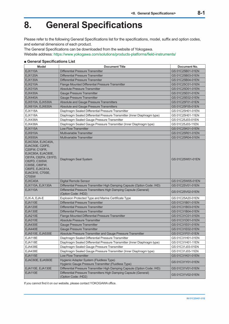
<8.GeneralSpecifications> 8-1
IM 01C25H01-01E
8. General SpecificationsPleaserefertothefollowingGeneralSpecificationslistforthespecifications,model,suffixandoptioncodes,and external dimensions of each product.TheGeneralSpecificationscanbedownloadedfromthewebsiteofYokogawa.Website address: https://www.yokogawa.com/solutions/products-platforms/field-instruments/
General Specifications List Model Document Title Document No.
EJX110A DifferentialPressureTransmitter GS 01C25B01-01ENEJX120A DifferentialPressureTransmitter GS 01C25B03-01ENEJX130A DifferentialPressureTransmiter GS 01C25B04-01ENEJX210A FlangeMountedDifferentialPressureTransmitter GS 01C25C01-01ENEJX310A Absolute Pressure Transmitter GS 01C25D01-01ENEJX430A Gauge Pressure Transmitter GS 01C25E01-01ENEJX440A Gauge Pressure Transmitter GS 01C25E02-01ENEJX510A, EJX530A Absolute and Gauge Pressure Transmitters GS 01C25F01-01ENEJX610A, EJX630A Absolute and Gauge Pressure Transmitters GS 01C25F05-01ENEJX118A DiaphragmSealedDifferentialPressureTransmitter GS 01C25H01-01ENEJX118A DiaphragmSealedDifferentialPressureTransmitter(InnerDiaphragmtype) GS 01C25H01-11ENEJX438A Diaphragm Sealed Gauge Pressure Transmitter GS 01C25J03-01ENEJX438A Diaphragm Sealed Gauge Pressure Transmitter (Inner Diaphragm type) GS 01C25J03-11ENEJX115A Low Flow Transmitter GS 01C25K01-01ENEJX910A Multivariable Transmitter GS 01C25R01-01ENEJX930A Multivariable Transmitter GS 01C25R04-01ENEJXC50A, EJXC40A, EJAC50E, C20FE, C20FW, C10FR, EJXC80A, EJAC80E, C81FA, C82FA, C81FD, C82FD, C30SW, C30SE, C80FW, C80FE, EJXC81A, EJAC81E, C70SE, C70SW
Diaphragm Seal System GS 01C25W01-01EN
EJXC40A Digital Remote Sensor GS 01C25W05-01ENEJX110A, EJX130A DifferentialPressureTransmitterHighDampingCapsule(OptionCode:/HD) GS 01C25V01-01ENEJX110A DifferentialPressureTransmittersHighDampingCapsule(General)
(Option Code: /HD2) GS 01C25V02-01EN
EJX-A, EJA-E ExplosionProtectedTypeandMarineCertificateType GS 01C25A20-01ENEJA110E DifferentialPressureTransmitter GS 01C31B01-01ENEJA120E DifferentialPressureTransmitter GS 01C31B03-01ENEJA130E DifferentialPressureTransmitter GS 01C31B04-01ENEJA210E FlangeMountedDifferentialPressureTransmitter GS 01C31C01-01ENEJA310E Absolute Pressure Transmitter GS 01C31D01-01ENEJA430E Gauge Pressure Transmitter GS 01C31E01-01ENEJA440E Gauge Pressure Transmitter GS 01C31E02-01ENEJA510E, EJA530E Absolute Pressure Transmitter and Gauge Pressure Transmitter GS 01C31F01-01ENEJA118E DiaphragmSealedDifferentialPressureTransmitter GS 01C31H01-01ENEJA118E DiaphragmSealedDifferentialPressureTransmitter(InnerDiaphragmtype) GS 01C31H01-11ENEJA438E Diaphragm Sealed Gauge Pressure Transmitter GS 01C31J03-01ENEJA438E Diaphragm Sealed Gauge Pressure Transmitter (Inner Diaphragm type) GS 01C31J03-11ENEJA115E Low Flow Transmitter GS 01C31K01-01ENEJAC60E, EJA560E Hygienic Adapter System (Fluidless Type)
Hygienic Gauge Pressure Transmitter (Fluidless Type) GS 01C31Y01-01EN
EJA110E, EJA130E DifferentialPressureTransmitterHighDampingCapsule(OptionCode:/HD) GS 01C31V01-01ENEJA110E DifferentialPressureTransmittersHighDampingCapsule(General)
(Option Code: /HD2) GS 01C31V02-01EN
Ifyoucannotfinditonourwebsite,pleasecontactYOKOGAWAoffice.
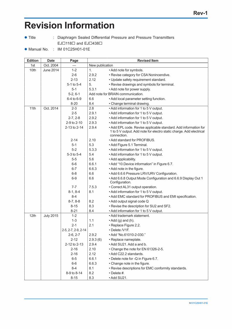
Rev-1
IM 01C25H01-01E
Revision Information Title : DiaphragmSealedDifferentialPressureandPressureTransmitters EJ118 and EJ438 Manual No. : IM 01C25H01-01E
Edition Date Page Revised Item1st Oct. 2004 — New publication
10th June 2014 1-2 1. • Add note for symbols.2-6 2.9.2 • Revise category for CSA Nonincendive.2-13 2.12 • Update safety requirement standard.
5-1 to 5-4 5. • Revise drawings and symbols for terminal.5-1 5.3.1 • Add note for power supply.
5-2, 6-1 Add note for BRAIN communication.6-4 to 6-9 6.6 • Add local parameter setting function.
8-20 8.4 • Change terminal drawing.11th Oct. 2014 2-3 2.8 • Add information for 1 to 5 V output.
2-5 2.9.1 • Add information for 1 to 5 V output.2-7, 2-8 2.9.2 • Add information for 1 to 5 V output.
2-9 to 2-10 2.9.3 • Add information for 1 to 5 V output.2-13 to 2-14 2.9.4 • Add EPL code. Revise applicable standard. Add information for
1 to 5 V output. Add note for electro static charge. Add electrical connection.
2-14 2.10 • Add standard for PROFIBUS.5-1 5.3 • Add Figure 5.1 Terminal. 5-2 5.3.3 • Add information for 1 to 5 V output.
5-3 to 5-4 5.4 • Add information for 1 to 5 V output.5-5 5.6 • Add applicability.6-6 6.6.1 • Add “10.Device information” in Figure 6.7.6-7 6.6.3 •Addnoteinthefigure.6-8 6.6 •Add6.6.6PressureLRV/URVConfiguration.6-9 6.6 •Add6.6.8OutputModeConfigurationand6.6.9DisplayOut1
Configuration.7-7 7.5.3 • Correct AL31 output operation.
8-1, 8-4 8.1 • Add information for 1 to 5 V output.8-4 •AddEMCstandardforPROFIBUSandEMIspecification.
8-7, 8-8 8.2 • Add output signal code Q8-15 8.3 • Revise the description for SU2 and SF2. 8-21 8.4 • Add information for 1 to 5 V output.
12th July 2015 1-2 • Add trademark statement.1-3 1.1 • Add (g) and (h).2-1 2.1 • Replace Figure 2.2.
2-5, 2-7, 2-9, 2-14 • Delete /V1F.2-6, 2-7 2.9.2 • Add “No.61010-2-030.”
2-12 2.9.3 (6) • Replace nameplate.2-12 to 2-13 2.9.4 • Add SU21. Add a and b.
2-16 2.10 • Change the note for EN 61326-2-5.2-16 2.12 • Add C22.2 standards.6-5 6.6.1 • Delete note for -Q in Figure 6.7.6-6 6.6.3 •Changenoteinthefigure.8-4 8.1 • Revise descriptions for EMC conformity standards.
8-9 to 8-14 8.2 • Delete #.8-15 8.3 • Add SU21.
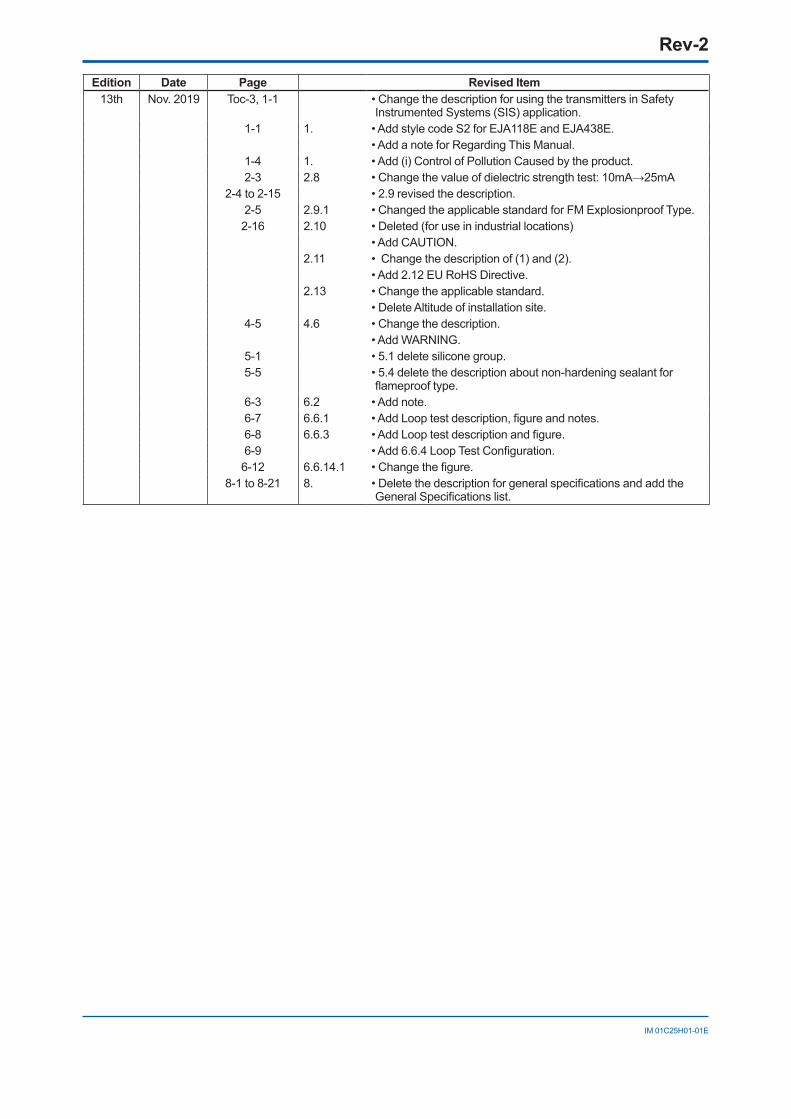
Rev-2
IM 01C25H01-01E
Edition Date Page Revised Item13th Nov. 2019 Toc-3, 1-1 • Change the description for using the transmitters in Safety
Instrumented Systems (SIS) application. 1-1 1. • Add style code S2 for EJA118E and EJA438E.
• Add a note for Regarding This Manual.1-4 1. • Add (i) Control of Pollution Caused by the product.2-3 2.8 •Changethevalueofdielectricstrengthtest:10mA→25mA
2-4 to 2-15 • 2.9 revised the description.2-5 2.9.1 • Changed the applicable standard for FM Explosionproof Type.2-16 2.10 • Deleted (for use in industrial locations)
• Add CAUTION.2.11 • Change the description of (1) and (2).
• Add 2.12 EU RoHS Directive.2.13 • Change the applicable standard.
• Delete Altitude of installation site.4-5 4.6 • Change the description.
• Add WARNING.5-1 • 5.1 delete silicone group.5-5 • 5.4 delete the description about non-hardening sealant for
flameprooftype.6-3 6.2 • Add note.6-7 6.6.1 •AddLooptestdescription,figureandnotes.6-8 6.6.3 •AddLooptestdescriptionandfigure.6-9 •Add6.6.4LoopTestConfiguration.6-12 6.6.14.1 •Changethefigure.
8-1 to 8-21 8. •DeletethedescriptionforgeneralspecificationsandaddtheGeneralSpecificationslist.