Embed Size (px)
Citation preview
Operating / Installation Instructions
No. 44.SCMB.E3.07/11 SCMB
DICKOW PUMPEN KG
Original manual

SCMB E3.07.11 E3.07.11 2 of 49
Table of Contents Table of Contents ......................................................................................................................................... 2 1. General................................................................................................................................................. 4 2. Safety ................................................................................................................................................... 5
2.1 Designation of Warning Notices................................................................................................. 5 2.2 Intended use ................................................................................................................................ 6 2.3 Avoidance of foreseeable operating errors ................................................................................. 6 2.4 Qualification of personnel........................................................................................................... 7 2.5 Additional safety regulations ...................................................................................................... 7 2.6 Safety instructions for the operator / user ................................................................................... 7 2.7 Safety instructions for maintenance, inspection and assembly .................................................. 8 2.8 Non-observance of the instruction manual ................................................................................. 8 2.9 Notices on explosion protection.................................................................................................. 8 2.10 Magnet coupling ....................................................................................................................... 11
3. Description......................................................................................................................................... 12 3.1 General description ................................................................................................................... 12 3.2 Design ....................................................................................................................................... 12 3.3 Pump sizes ................................................................................................................................ 12 3.4 Identification ............................................................................................................................. 13 3.5 Design ....................................................................................................................................... 14 3.6 Scope of supply......................................................................................................................... 15 3.7 Dimensions and Weights .......................................................................................................... 15
4. Handling / Storage / Disposal ............................................................................................................ 16 4.1 Handling.................................................................................................................................... 16 4.2 Storage / Preservation ............................................................................................................... 17 4.3 Return of pump ......................................................................................................................... 17 4.4 Disposal .................................................................................................................................... 18
5. Installation / Mounting ...................................................................................................................... 19 5.1 Safety Instructions .................................................................................................................... 19 5.2 Foundation ................................................................................................................................ 19 5.3 Installation of pump unit ........................................................................................................... 20 5.4 Piping ........................................................................................................................................ 20 5.5 Insulation .................................................................................................................................. 23 5.6 Electrical connection of the pump unit ..................................................................................... 23
6. Commissioning / Decommissioning.................................................................................................. 25 6.1 Commissioning ......................................................................................................................... 25 6.2 Operating the pump................................................................................................................... 26 6.3 Impeller trimming ..................................................................................................................... 26 6.4 Operating limits ........................................................................................................................ 26 6.5 Switching off the pump............................................................................................................. 27 6.6 Decommissioning ..................................................................................................................... 28
7. Maintenance / Servicing / Inspection ................................................................................................ 29 7.1 Safety regulations...................................................................................................................... 29 7.2 Operating surveillance .............................................................................................................. 30 7.3 Drainage and Disposal .............................................................................................................. 31 7.4 Disassembly of pump unit ........................................................................................................ 31 7.5 Inspection.................................................................................................................................. 35 7.6 Assembly of pump unit ............................................................................................................. 37 7.7 Bolt torques............................................................................................................................... 41
8. Troubleshooting................................................................................................................................. 42
Table of Contents
SCMB E3.07.11 E3.07.11 3 of 49
9. Interchangeability .............................................................................................................................. 44 10. Sectional drawings ........................................................................................................................ 45
10.1 Pump size 256 - 406.................................................................................................................. 45 10.2 Pump size 456 + 506................................................................................................................. 46 10.3 Pump size 656 ........................................................................................................................... 47 10.4 Special designs.......................................................................................................................... 47
11. Certificates .................................................................................................................................... 48 11.1 EG-Konformitätsbescheinigung ............................................................................................... 48 11.2 Document of Compliance ......................................................................................................... 49
Table of Contents
SCMB E3.07.11 E3.07.11 4 of 49
1. General This instruction manual describes the proper and safe usage of the pump during all operating phases. The instruction manual does not consider local regulations. Adherence to those is the responsibility of the owner. The name tag states pump type and size, the most important operating data as well as the pump serial number. The serial number is a precise description of the pump unit and serves as identification for all following procedures. In the event of damage the Customer Service of Dickow Pumpen must immediately be informed in order to maintain guarantee claims. For installation of supplied interchangeable units, the respective subchapters of "Maintenance, Servicing, Inspection" must be observed. Applicable documents:
- Pump data sheet - Dimensional drawing - Sectional drawing - Parts lists - Sub-supplier documentation
1. General
SCMB E3.07.11 E3.07.11 5 of 49
2. Safety The manual includes basic instructions for installation, operation and maintenance. Only if these instructions are strictly observed, a safe handling of pump or pump unit is guaranteed and personal injury and material damage is avoided. All the safety instructions in this manual must be considered. This manual must be thoroughly reviewed and completely understood by the qualified personnel / operator before attempting assembly and start-up. The manual must consistently be available on site. Indications and plates attached to the pump must be followed and kept in legible condition.
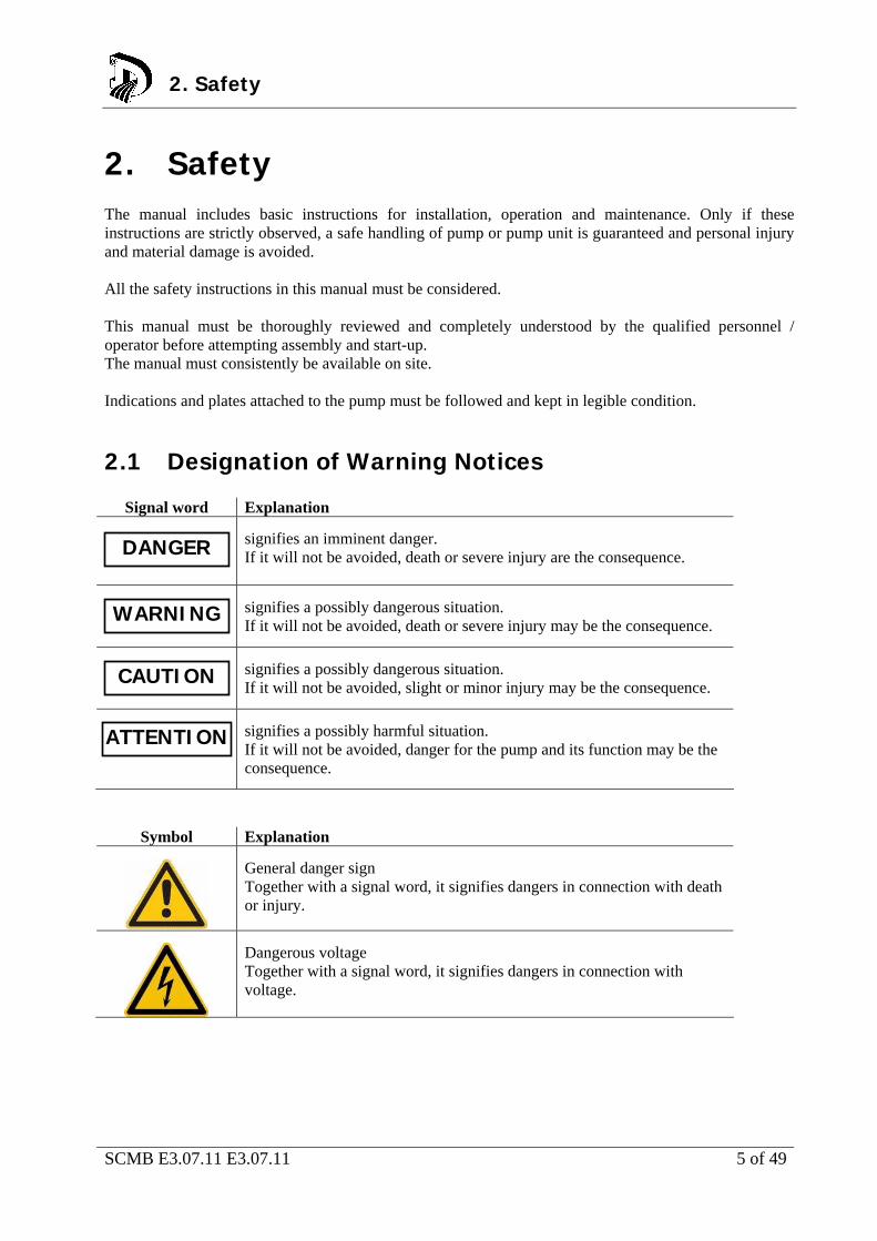
2.1 Designation of Warning Notices
Signal word Explanation
signifies an imminent danger. If it will not be avoided, death or severe injury are the consequence.
signifies a possibly dangerous situation. If it will not be avoided, death or severe injury may be the consequence.
signifies a possibly dangerous situation. If it will not be avoided, slight or minor injury may be the consequence.
signifies a possibly harmful situation. If it will not be avoided, danger for the pump and its function may be the consequence.
Symbol Explanation
General danger sign Together with a signal word, it signifies dangers in connection with death or injury.
Dangerous voltage Together with a signal word, it signifies dangers in connection with voltage.
2. Safety
DANGER
WARNING
CAUTION
ATTENTION
SCMB E3.07.11 E3.07.11 6 of 49
Warning from magnetic field Together with a signal word, it signifies dangers in connection with magnetic fields.
Hot surface Together with a signal word, it signifies dangers in connection with hot surfaces.
Explosion protection Gives information on protection from explosion development in hazardous area according to EC-Directive 94/9/EG.
Mechanical breakdown Together with the signal word ATTENTION, it signifies dangers for the pump and its function.
Notice Provides recommendation and useful information for handling the product.
2.2 Intended use The pump / pump unit may only be operated in the application area which is described in the relevant pump data sheet. This applies for instance to pumped liquid, flow, speed, pressure, temperature and motor power. Further points to be observed: Operate pump in technically faultless condition only.
Never operate pump incompletely assembled.
Never operate pump without liquid.
Observe the specification in the pump data sheet / operating manual regarding the minimum flow.
Observe the specification in the pump data sheet / operating manual regarding the maximum flow.
Never throttle pump on suction side.
Maximum speed is 1450 rpm (+10%) at 50 cycles and 1750 rpm (+10%) at 60 cycles. Consider deviations mentioned in the pump data sheet
2.3 Avoidance of foreseeable operating errors Never open shut-off valves in excess of the allowable range. This would cause exceedance of the
maximum flow and possible cavitation damage.
Never exceed the allowable application limits regarding pressure and temperature which are specified in the pump data sheet.
Consider and adhere to all safety instructions and other notices mentioned in the operating manual.
2. Safety2. Safety
SCMB E3.07.11 E3.07.11 7 of 49
2.4 Qualification of personnel The personnel must possess the relevant qualification for assembly, operation, maintenance and inspection of the pump unit. Responsibility, competence and supervision must be strictly regulated by the owner. Skill of the personnel shall be improved by training. Training course can be held by the technical staff of Dickow Pumpen.
2.5 Additional safety regulations Besides the safety instructions mentioned in this manual, the following additional regulations apply: Accident prevention regulations
Explosion proof regulations
Safety regulations for handling hazardous materials
Applicable standards and laws
2.6 Safety instructions for the operator / user Protection against contact with hot and cold components must be provided by customer.
Coupling guard and hand guard on the pump / pump unit must not be removed during operation.
Pump must always be earth connected / grounded.
Protective equipment for personnel must be provided and used.
Toxic liquid leakage must be drained off safely, without endangering individuals and environment. Legal requirements must be observed.
Danger through electric energy must be excluded.
2. Safety
SCMB E3.07.11 E3.07.11 8 of 49
2.7 Safety instructions for maintenance, inspection and assembly Alteration works or modifications on the pump are only allowed after consulting Dickow Pumpen.
Only original parts or parts approved by Dickow shall be used.
Repairs on the pump / pump unit may only be done during shutdown.
The pump casing must have cooled down to ambient temperature.
The pump must be depressurized and drained.
Consider the procedure for decommissioning according to chapter 6.6.
Pumps handling products dangerous to health must be decontaminated according to chapter 4.4
Coupling guard and hand guard must be mounted again after completion of the works.
Works on the pump unit may be done only with disconnected electricity.
Secure the pump unit against unintentional switch-on.
2.8 Non-observance of the instruction manual Non-observance of this manual leads to loss of warranty and damage claims. Non-observance will involve the following risks: Endangering of individuals through electrical, thermal, mechanical and chemical impacts.
Danger through explosions.
Danger through breakdown of essential functions.
Endangering of environment through leakage of toxic liquids.
2.9 Notices on explosion protection Operation in explosive areas requires stringent attention to this
chapter.
Only pumps with respective identification are allowed to be used in explosive areas.
Pumps must be designated for this service in the pump data sheet.
Intended use must be warranted.
Inadmissible operating conditions must be avoided in any case.
Special conditions apply for operation in compliance with EC-Directive 94/9/EG (ATEX). The symbol shown here signifies the chapters in this manual which require special attention.
2. Safety
DANGER
SCMB E3.07.11 E3.07.11 9 of 49
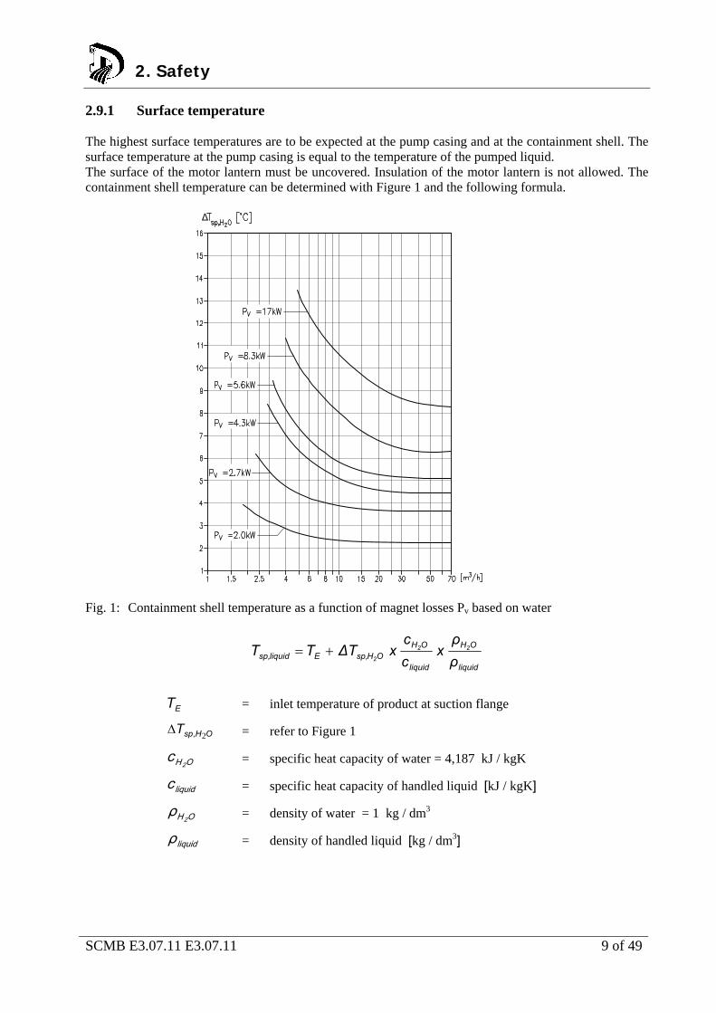
2.9.1 Surface temperature The highest surface temperatures are to be expected at the pump casing and at the containment shell. The surface temperature at the pump casing is equal to the temperature of the pumped liquid. The surface of the motor lantern must be uncovered. Insulation of the motor lantern is not allowed. The containment shell temperature can be determined with Figure 1 and the following formula.
Fig. 1: Containment shell temperature as a function of magnet losses Pv based on water
liquid
OH
liquid
OHOHsp,Eliquidsp, ρ
ρx
c
cx∆TTT 22
2
ET = inlet temperature of product at suction flange
OH,spT 2 = refer to Figure 1
OH 2c = specific heat capacity of water = 4,187 kJ / kgK
liquidc = specific heat capacity of handled liquid [kJ / kgK]
OH 2ρ = density of water = 1 kg / dm3
liquidρ = density of handled liquid [kg / dm3]
∆
2. Safety

SCMB E3.07.11 E3.07.11 10 of 49
If pumps are equipped with ceramic or PEEK containment shell, no magnet losses Pv will occur.
The surface temperature at the containment shell is equal to the temperature of the handled liquid.
2.9.2 Monitoring devices The pump may be operated only within the limits given in the pump data sheet and on the name tag. In case the owner cannot maintain the operating limits, monitoring devices are required. The following risks must be considered: Plugging of internal circulation channels
The inner liquid filled area of the magnet coupling is cooled by an internal circulation. Interruption of this internal circulation through certain properties of the product can cause an inadmissible temperature rise.
Desynchronisation of the magnet coupling
Overstressing, overheating or non-observance of the design data may result in desynchronisation of the magnet coupling. The generated heat energy may cause temperature rise of the containment shell.
Solids between inner magnet and containment shell Large solids may become wedged between inner magnet and containment shell and cause inadmissible temperature rise at the containment shell through friction.
Product leakage If a containment shell is damaged (= rare failure) and leaking product can endanger the environment, a leakage monitor should be provided. Interaction with adjoining materials must be considered.
Operation below the minimum flow Operation above the maximum flow
Dry run
A temporary dry run can already lead to inadmissible surface temperatures and wear due to the small clearance between side channel impellers and stage disks.
The following monitoring devices can be supplied: Level switch to avoid dry running.
Temperature monitoring of the containment shell for controlling elevated temperatures in the containment shell.
Power monitor for controlling minimum flow and/or maximum flow and detection of dry run and desynchronisation of the magnet coupling.
Monitoring of the inner area of the bearing bracket to detect leakage due to containment shell damage.
NOTE
2. Safety
SCMB E3.07.11 E3.07.11 11 of 49
2.10 Magnet coupling Strong magnetic field from the area of the magnet coupling or from single
magnets.
Danger to life for individuals with pace maker ! Disturbance of magnetic data media, electronic devices, components and instruments! Uncontrolled attractive force between magnetic components, tools etc.!
A safe distance of 0,3 m minimum must be maintained. The safe distance refers to inner and outer magnets which are not yet installed in the pump. In mounted condition, the magnetic field is completely shielded. There is no danger through magnetic fields from an assembled pump. This refers also to pace makers.
2. Safety
DANGER
SCMB E3.07.11 E3.07.11 12 of 49
3. Description 3.1 General description This pump is used where ever sealless design and selfpriming ability is required. This applies for instance to dangerous, explosive, toxic and other harmful but clean or gaseous liquids without solids which are handled in the chemical, petrochemical and general industry.
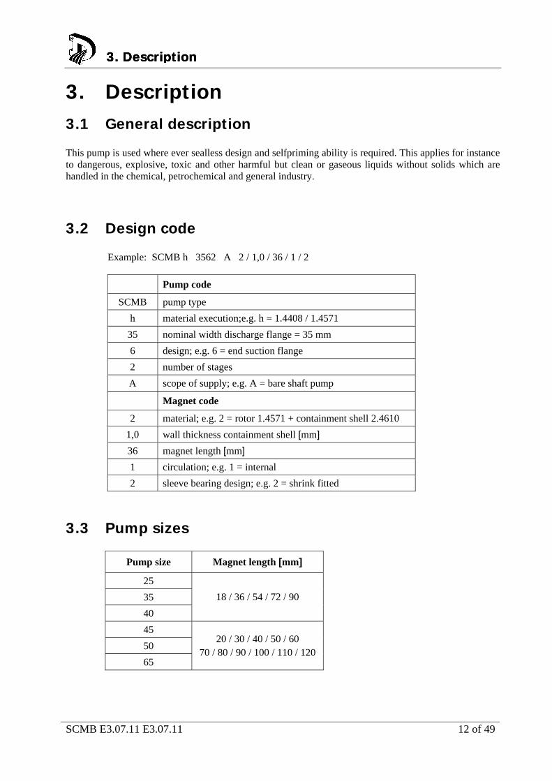
3.2 Design code Example: SCMB h 3562 A 2 / 1,0 / 36 / 1 / 2
Pump code
SCMB pump type
h material execution;e.g. h = 1.4408 / 1.4571
35 nominal width discharge flange = 35 mm
6 design; e.g. 6 = end suction flange
2 number of stages
A scope of supply; e.g. A = bare shaft pump
Magnet code
2 material; e.g. 2 = rotor 1.4571 + containment shell 2.4610
1,0 wall thickness containment shell [mm]
36 magnet length [mm]
1 circulation; e.g. 1 = internal
2 sleeve bearing design; e.g. 2 = shrink fitted
3.3 Pump sizes
Pump size Magnet length [mm]
25
35
40
18 / 36 / 54 / 72 / 90
45
50
65
20 / 30 / 40 / 50 / 60 70 / 80 / 90 / 100 / 110 / 120
3. Description 3. Description 3. Description
SCMB E3.07.11 E3.07.11 13 of 49
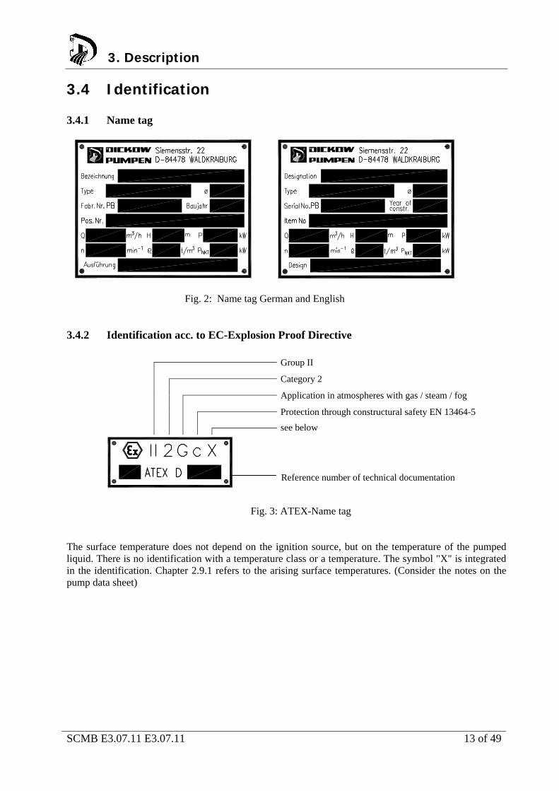
3.4 Identification 3.4.1 Name tag
Fig. 2: Name tag German and English 3.4.2 Identification acc. to EC-Explosion Proof Directive
Group II
Category 2
Application in atmospheres with gas / steam / fog
Protection through constructural safety EN 13464-5
see below
Reference number of technical documentation
Fig. 3: ATEX-Name tag
The surface temperature does not depend on the ignition source, but on the temperature of the pumped liquid. There is no identification with a temperature class or a temperature. The symbol "X" is integrated in the identification. Chapter 2.9.1 refers to the arising surface temperatures. (Consider the notes on the pump data sheet)
3. Description
SCMB E3.07.11 E3.07.11 14 of 49
3.5 Design Design
side channel pump
horizontal installation
multistage
selfpriming
close coupled design
Pump casing
end suction flange, vertical suction flange possible
vertical discharge flange
cast-on feet
Impeller
suction impeller
star-shaped side channel impellers
Bearing
pump end: product lubricated sleeve bearings
Shaft sealing
magnet coupling
3.5.1 Magnet coupling The drive power is transmitted by the motor - through the magnetic field lines - via the outer magnets to the inner magnet coupling. The inner and outer magnets are tied together through magnetic field lines and are therefore synchronized. No slip exists, the motor speed complies with the coupling speed. The pump shaft with impeller and driven inner magnet is carried by wetted sleeve bearings. The SiC components have an almost unlimited service life as long as a stable fluid film is available between the sliding surfaces. The heat in the metallic containment shells, generated through eddy currents, is dissipated through an internal circulation flow. The internal circulation is an additional safety against exceedance of boiling point in the magnet chamber and serves as a lubrication of the sleeve bearings.
3. Description 3. Description
SCMB E3.07.11 E3.07.11 15 of 49
3.6 Scope of supply Depending on the pump execution, the following items belong to the scope of supply: Pump
Casted base plate respectively welded frame of stiff design
Drive motor
Special accessories if required
3.7 Dimensions and Weights Dimensions and weights can be taken from the foundation plan / dimensional drawing.
3. Description 3. Description
SCMB E3.07.11 E3.07.11 16 of 49
4. Handling / Storage / Disposal
4.1 Handling
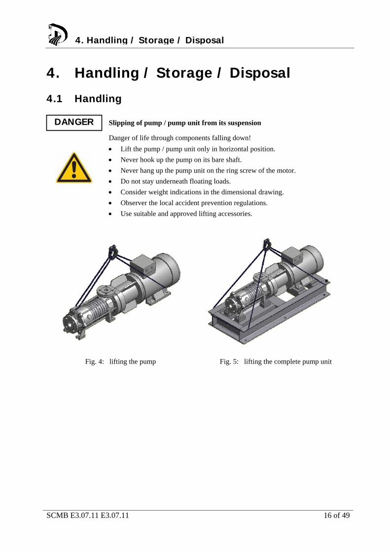
Slipping of pump / pump unit from its suspension
Danger of life through components falling down!
Lift the pump / pump unit only in horizontal position.
Never hook up the pump on its bare shaft.
Never hang up the pump unit on the ring screw of the motor.
Do not stay underneath floating loads.
Consider weight indications in the dimensional drawing.
Observer the local accident prevention regulations.
Use suitable and approved lifting accessories.
Fig. 4: lifting the pump Fig. 5: lifting the complete pump unit
DANGER
4. Handling / Storage / Disposal

SCMB E3.07.11 E3.07.11 17 of 49
4.2 Storage / Preservation Damage during storage through moisture or dirt.
Corrosion and / or contamination of the pump !
Outside storage requires a watertight cover over pump or over packed pump and accessories.
Wetted, contaminated or damaged openings and joints.
Leakage or damage of the pump !
Plugged openings should be uncovered only during installation.
The following measures are recommended for storage of the pump / pump unit: Store the pump in a sheltered dry place with constant air humidity.
Turn the shaft manually once a month.
New pumps of material GGG (ductile iron) and ferritic cast steel are covered inside with anti-corrosive agent and dewatering-fluid. The maximum dry storage period is 12 months. For storing a pump that has been in operation already, consider chapter 6.6.
4.3 Return of pump Drain the pump properly considering chapter 7.3.
Rinse and clean the pump in general, especially when handling dangerous, explosive, hot or other risky liquids.
A Document of Compliance completely filled in must always be attached to the pump. Refer to chapter 11.2.
If required, a Document of Compliance can be downloaded under www.dickow.de.
http://www.dickow.de/unbedenk-en.pdf
4. Handling / Storage / Disposal
ATTENTION
ATTENTION
NOTE
SCMB E3.07.11 E3.07.11 18 of 49
4.4 Disposal
Liquids dangerous to health
Danger for individuals and environment !
Collect and dispose rinsing water and residual liquid.
Wear protective clothing and face mask.
Consider the legal regulations for disposal of liquids dangerous to health.
1. Disassemble pump / pump unit.
2. Collect grease and oil.
3. Separate pump materials
4. Dispose according to the local regulations.
4. Handling / Storage / Disposal
WARNING
SCMB E3.07.11 E3.07.11 19 of 49
5. Installation / Mounting 5.1 Safety Instructions Improper installation in explosive area
Danger of explosion !
Consider the local applicable explosion proof regulations.
Consider indications on the pump data sheet and on the name tag of pump and motor.
Strong magnetic field from the area of the magnet coupling or from single
magnets
Danger to life for individuals with pace maker ! Disturbance on magnetic data media, electronic devices, components and instruments ! Uncontrolled attractive force between magnetic components, tools etc. ! A safe distance of 0,3 m minimum must be maintained.
Consider additional notes in chapter 2.10.
5.2 Foundation Installation on weak and unstable foundations
Personal injury and material damage !
Consider sufficient concrete strength (minimum class XO) of the foundation acc. to DIN 1045.
Place the pump unit on hardened foundation only.
Place the pump unit on level and even surfaces only.
Consider weight indications of dimensional drawing.
DANGER
DANGER
5. Installation / Mounting
WARNING
SCMB E3.07.11 E3.07.11 20 of 49
5.3 Installation of pump unit 5.3.1 Installation on foundation 1. Place the pump unit on the foundation and align it with a water-level.
Allowable deviation: 0,2 mm/m
2. Insert shims for height compensation. Always insert them both-sided near the foundation bolts between baseplate and foundation.
3. If the space between the foundation bolts is > 600 mm, insert additional shims in the middle between the foundation bolts.
4. All shims must seat solidly.
5. Hook the foundation bolts into the provided bore.
6. Concrete the foundation bolts.
7. Align the base plate after concrete has hardened.
8. Tighten the foundation bolts evenly.
9. Pour the base plate with vibration-free concrete of normal graining with a water-cement-value (W/Z-value) ≤ 0,5. Provide a pourable consistency by using a mobile solvent. Cure of concrete according to DIN 1045.
5.3.2 Installation without foundation Installation without foundation requires a solid and even ground. 1. Place the pump unit on stilts and align it with a water-level.
2. For height compensation, loosen screws and counter nuts of stilts.
3. Adjust the nut until available height differences are compensated.
4. Fasten the counter nuts of the stilts.
5.4 Piping
Exceedance of the allowable loads at the pump flanges
Danger to life from leaking hot, toxic, caustic or flammable liquids.
Do not use the pump as an anchor point for piping.
Support piping before the pump and connect it stress-free.
Consider allowable flange forces and moments according to chapter 5.4.2.
Compensate expansion of the piping in case of high temperatures.
5. Installation / Mounting
DANGER
SCMB E3.07.11 E3.07.11 21 of 49
5.4.1 Suction pipe Layout of suction pipe requires special attention. NPSH Available and NPSH Required must be clearly defined. Pay attention to the following: Mounting of elbows close to the pump suction must be avoided. Provide a straight pipe of
minimum two suction pipe diameters
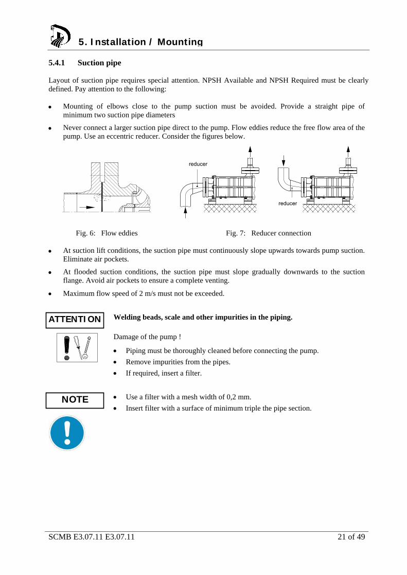
Never connect a larger suction pipe direct to the pump. Flow eddies reduce the free flow area of the pump. Use an eccentric reducer. Consider the figures below.
Fig. 6: Flow eddies Fig. 7: Reducer connection
At suction lift conditions, the suction pipe must continuously slope upwards towards pump suction.
Eliminate air pockets.
At flooded suction conditions, the suction pipe must slope gradually downwards to the suction flange. Avoid air pockets to ensure a complete venting.
Maximum flow speed of 2 m/s must not be exceeded.
Welding beads, scale and other impurities in the piping.
Damage of the pump !
Piping must be thoroughly cleaned before connecting the pump.
Remove impurities from the pipes.
If required, insert a filter.
Use a filter with a mesh width of 0,2 mm.
Insert filter with a surface of minimum triple the pipe section.
5. Installation / Mounting
reducer
reducer
ATTENTION
NOTE
SCMB E3.07.11 E3.07.11 22 of 49
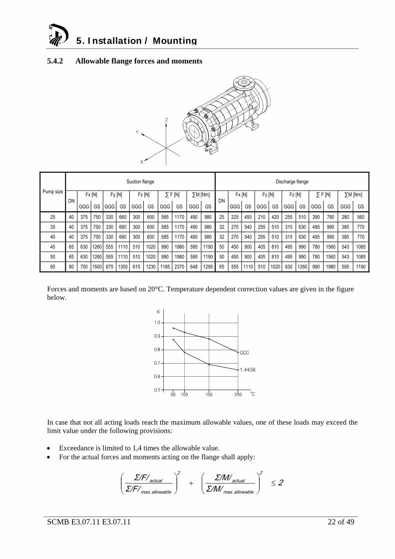
5.4.2 Allowable flange forces and moments
Suction flange Discharge flange
Fx [N] Fy [N] Fz [N] ∑ F [N] ∑M [Nm] Fx [N] Fy [N] Fz [N] ∑ F [N] ∑M [Nm] Pump size
DN GGG GS GGG GS GGG GS GGG GS GGG GS
DN GGG GS GGG GS GGG GS GGG GS GGG GS
25 40 375 750 330 660 300 600 585 1170 490 980 25 225 450 210 420 255 510 390 780 280 560
35 40 375 750 330 660 300 600 585 1170 490 980 32 270 540 255 510 315 630 495 990 385 770
40 40 375 750 330 660 300 600 585 1170 490 980 32 270 540 255 510 315 630 495 990 385 770
45 65 630 1260 555 1110 510 1020 990 1980 595 1190 50 450 900 405 810 495 990 780 1560 543 1085
50 65 630 1260 555 1110 510 1020 990 1980 595 1190 50 450 900 405 810 495 990 780 1560 543 1085
65 80 750 1500 675 1350 615 1230 1185 2370 648 1295 65 555 1110 510 1020 630 1260 990 1980 595 1190
Forces and moments are based on 20°C. Temperature dependent correction values are given in the figure below.
In case that not all acting loads reach the maximum allowable values, one of these loads may exceed the limit value under the following provisions: Exceedance is limited to 1,4 times the allowable value. For the actual forces and moments acting on the flange shall apply:
2Σ/M/
Σ/M/Σ/F/
Σ/F/ 2
allowable max.
actual2
allowable max.
actual
5. Installation / Mounting
SCMB E3.07.11 E3.07.11 23 of 49
5.5 Insulation Wetted casing parts adopt the temperature of the pumped liquid.
Risk of burns !
Insulate casing parts
Attach protective device
Heat accumulation in the motor lantern
Bearing damage !
Do not insulate the motor lantern
5.6 Electrical connection of the pump unit Improper electrical installation
Danger of explosion !
Electrical installation requires additionally observance of IEC 60079-14.
Explosion proof motors shall be connected through motor protection switch only
Working on the pump unit by unqualified personnel
Danger to life through electric shock !
Electrical connection must be performed by qualified electrician only.
Regulations IEC 30364 and IEC 60079 must be considered.
Incorrect power connection
Short circuit !
Adhere to connection conditions of local energy supply companies.
Star-Delta starting leads to a high torque increase when switching from star to delta, this can cause decoupling of the magnets. Therefore, star-delta starting is not suitable for magnetic coupled pumps. For reducing the starting current, a soft-starter is recommended.
5. Installation / Mounting
WARNING
ATTENTION
DANGER
DANGER
WARNING
NOTE
SCMB E3.07.11 E3.07.11 24 of 49
Proceedings: 1. Check for compliance of the available supply voltage with the indications on the motor name tag.
2. Select suitable connection method.
3. Check for identical rotating direction of motor and pump. Consider the rotating direction arrow of
the pump !
Observe the instruction manual of the motor !
5.6.1 Checking rotating direction
Temperature rise through parts touching each other
Danger of explosion !
Never check rotating direction with dry pump.
Wrong rotating direction of motor and pump
Damage of the pump !
Consider the rotating direction arrow on the pump.
1. Start motor briefly. Note rotating direction of the motor.
2. Rotating direction of the motor must comply with the rotating direction arrow on the pump.
3. In case of wrong rotating direction, change the cables in the motor terminal box.
NOTE
DANGER
ATTENTION
5. Installation / Mounting
SCMB E3.07.11 E3.07.11 25 of 49
6. Commissioning / Decommissioning 6.1 Commissioning The following points must be checked prior to start-up; The pump unit is correctly electronically connected to all relevant protective devices.
The pump is filled with liquid.
Rotating direction has been checked.
All additional connections are connected and fully functional.
After a longer standstill period, the measures mentioned in chapter 7 "Maintenance/Servicing/Inspection" must be considered and performed.
6.1.1 Filling the pump Formation of explosive atmosphere inside the pump
Danger of explosion !
The pump must permanently be filled with liquid.
Appropriate monitoring measures must be provided.
1. Fill the pump with liquid.
2. Open shut-off valve in suction pipe completely.
3. Open all additional connections completely (e.g. external circulation, external flush)
6.1.2 Starting the pump Exceedance of allowable pressure- and temperature limits
Danger of explosion ! Leakage of hot or toxic liquid
Never operate pump with closed shut-off valves in suction and/or discharge pipe.
Start-up pump unit only against partially opened shut-off valve on discharge side.
Elevated temperature through dry run
Danger of explosion !
Never operate pump in empty condition.
Always fill up pump properly.
Operate pump only within the allowable operating range.
6. Commissioning / Decommissioning
DANGER
6. Commissioning / Decommissioning6. Commissioning / Decommissioning
DANGER
DANGER

SCMB E3.07.11 E3.07.11 26 of 49
1. Open shut-off valve completely in suction pipe
2. Open shut-off valve partially in discharge pipe
3. Switch on the motor. Pay attention to the synchronicity of pump and motor. Decoupling leads to low differential head and noise in the magnetic coupling.
4. When the pressure gauge indicates pressure, open shut-off valve on discharge side until the duty point is reached.
Elevated temperature through decoupling of the magnet coupling
Danger of explosion !
Switch off pump unit immediately.
Eliminate cause of malfunction.
6.2 Operating the pump High surface temperatures through hot liquids
Risk of burns !
Avoid touching the pump surface.
Wear protective clothing.
Abnormal noises, vibrations, temperatures or leakage
Damage of the pump !
Switch off the pump immediately.
Only restart the pump unit after cause of trouble has been eliminated.
6.3 Impeller trimming Impeller trimming is not possible for this pump type.
6.4 Operating limits Exceedance of operating limits regarding pressure, temperature and speed
Danger of explosion ! Leaking hot or toxic liquid !
Maintain the allowable service conditions specified in the pump data sheet.
Avoid operation against closed shut-off valve.
Never operate pump at a temperature higher than specified in the pump data sheet.
DANGER
WARNING
ATTENTION
6. Commissioning / Decommissioning6. Commissioning / Decommissioning6. Commissioning / Decommissioning
DANGER
SCMB E3.07.11 E3.07.11 27 of 49
6.4.1 Flow rate If not stated otherwise in the pump data sheet, the following applies: Qmin = 0,25 x Qopt
Qmax = 1,2 x Qopt
6.4.2 Switching frequencies Elevated surface temperature of the motor
Danger of explosion !
When using explosion proof motors, consider the information in the motor manual regarding switching frequencies.
The switching frequencies are defined by the maximum temperature rise of the motor and depend on the power reserve of the motor during operation and on the starting conditions.
Read instruction manual of motor manufacturer !
6.5 Switching off the pump 1. Keep shut-off valve in suction pipe open.
2. Close shut-off valve in discharge pipe.
3. Switch off the motor and watch for steady run down.
In case a non-return valve is installed in the discharge pipe, the shut-off valve can remain open. A counter pressure must be available.
For a longer standstill period, the following must be observed: Liquids which tend to polymerization, crystallization or solidification, must be drained completely.
If required, rinse the pump with a suitable liquid.
Close shut-off valve in the suction pipe.
Flush connections must be closed.
6. Commissioning / Decommissioning
NOTE
DANGER
NOTE
SCMB E3.07.11 E3.07.11 28 of 49
6.6 Decommissioning The pump unit remains in the piping:
Provide sufficient amount of liquid for the test runs.
Switch on the pump unit regularly monthly or quarterly.
The pump unit will be dismantled and stored:
Empty the pump properly.
Observe the safety instructions acc. to chapter 7.1 / 7.3.
Spray the inside of the pump casing with preservation agent. Not required for stainless steel pumps.
Spray preservation agent through suction and discharge flange.
Plug suction and discharge flanges, e.g. with plastic caps.
Lubricate all unpainted outside surfaces of the pump with oil and grease free of silicone. Not required for stainless steel pumps.
Pay attention to additional notes in chapter 4.2.
6. Commissioning / Decommissioning
SCMB E3.07.11 E3.07.11 29 of 49
7. Maintenance / Servicing / Inspection 7.1 Safety regulations Improper maintained pump unit
Danger of explosion !
Maintain the pump unit regularly
Establish a maintenance schedule
Strong magnetic field in the area of magnet coupling or single magnets
Danger to life for individuals with cardiac pacemakers!
Disruption of magnetic data medium, electric devices, components and instruments! Uncontrolled attractive force between magnetic components, tools etc. !
A safe distance of minimum 0,3 m must be maintained..
Unintentional switching-on of the pump unit
Risk of injury through moving components !
Works on the pump unit may be done only at disconnected electricity.
Secure the pump unit against unintentional switch-on.
Hot liquids
Risk of injury!
Let the pump unit cool down to ambient temperature.
Liquids dangerous to health
Risk of injury!
Consider legal requirements.
Take safety measures for individuals and environment when draining the pumped liquid.
Decontaminate the pumps.
The user must assure that maintenance, inspection and assembly is performed by qualified personnel. These persons must have studied this operating manual comprehensively. A maintenance schedule needs a minimum of effort and may avoid expensive repairs. Any use of force on the pump unit must be avoided.
7. Maintenance / Servicing / Inspection
DANGER
DANGER
WARNING
WARNING
WARNING
SCMB E3.07.11 E3.07.11 30 of 49
7.2 Operating surveillance Elevated surface temperature through hot running antifriction bearings
Danger of explosion ! Fire hazard !
Check antifriction bearings regularly for running noise.
Wear caused by dry run
Damage of the pump !
Never operate an empty pump.
Never close the shut-off valve in suction pipe during operation.
Exceedance of the allowable liquid temperature
Damage of the pump !
Operation against closed discharge valve is not allowed.
Consider the temperature indications in the pump data sheet..
The following requires regular checking during operation: The pump must always run steady and vibration-free.
Check antifriction bearings for running noise. Vibrations, noises and increased power consumption are signs of wear.
Clean the filter in the suction pipe regularly.
7.2.1 Lubrication of sleeve bearings Sleeve bearings require a stable liquid film. Checking on wear must be done after dry run or cavitation.
when vibrations, noises and power consumption are increasing.
DANGER
ATTENTION
ATTENTION
7. Maintenance / Servicing / Inspection
SCMB E3.07.11 E3.07.11 31 of 49
7.3 Drainage and Disposal Pumped liquids dangerous to life
Endangering for individuals and environment !
Collect flushing liquid and possible residual liquid and dispose it.
Wear protective clothing and face masks.
Consider legal requirements concerning disposal of liquids.
Drainage of pumped liquids through the drain plugs at the casing, through a connected shut-off valve or through a flange. Mode of drainage and position can be taken from the dimensional drawing !
7.4 Disassembly of pump unit 7.4.1 General instructions Pay attention to safety instructions of chapter 7.1.
Working on the motor requires observance of the documentation provided by the motor manufacturer.
Consider the sectional drawings when disassembling.
In case of damage, our service department can be contacted.
Working on the pump unit without sufficient preparation
Risk of injury !
Switch off the pump unit properly.
Close shut-off valves on suction and discharge side.
Drain and depressurize the pump.
Flush connections must be closed.
Let the pump unit cool down to ambient temperature.
7.4.2 Removal of driver 1. Disconnect the motor.
2. Remove the hold down bolts of the motor from the baseplate.
3. Remove hexagon nuts 920.2.
4. Pull off the motor with motor lantern 341 and drive rotor 818.1.
Tilting the motor
Squeezing of hands and feet !
Secure the motor by lifting or bracing.
7. Maintenance / Servicing / Inspection
WARNING
DANGER
7. Maintenance / Servicing / Inspection
WARNING
SCMB E3.07.11 E3.07.11 32 of 49
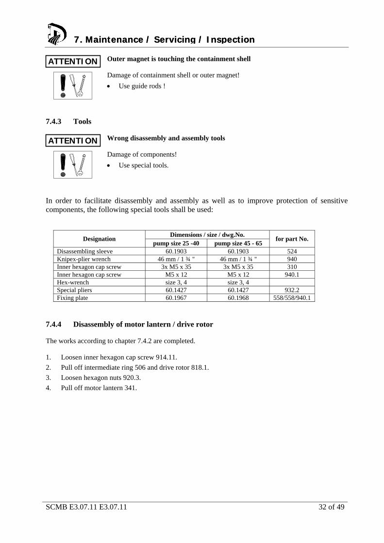
Outer magnet is touching the containment shell
Damage of containment shell or outer magnet!
Use guide rods !
7.4.3 Tools Wrong disassembly and assembly tools
Damage of components!
Use special tools.
In order to facilitate disassembly and assembly as well as to improve protection of sensitive components, the following special tools shall be used:
Dimensions / size / dwg.No. Designation
pump size 25 -40 pump size 45 - 65 for part No.
Disassembling sleeve 60.1903 60.1903 524 Knipex-plier wrench 46 mm / 1 ¾ " 46 mm / 1 ¾ " 940 Inner hexagon cap screw 3x M5 x 35 3x M5 x 35 310 Inner hexagon cap screw M5 x 12 M5 x 12 940.1 Hex-wrench size 3, 4 size 3, 4 Special pliers 60.1427 60.1427 932.2 Fixing plate 60.1967 60.1968 558/558/940.1
7.4.4 Disassembly of motor lantern / drive rotor The works according to chapter 7.4.2 are completed. 1. Loosen inner hexagon cap screw 914.11.
2. Pull off intermediate ring 506 and drive rotor 818.1.
3. Loosen hexagon nuts 920.3.
4. Pull off motor lantern 341.
ATTENTION
ATTENTION
7. Maintenance / Servicing / Inspection7. Maintenance / Servicing / Inspection
SCMB E3.07.11 E3.07.11 33 of 49
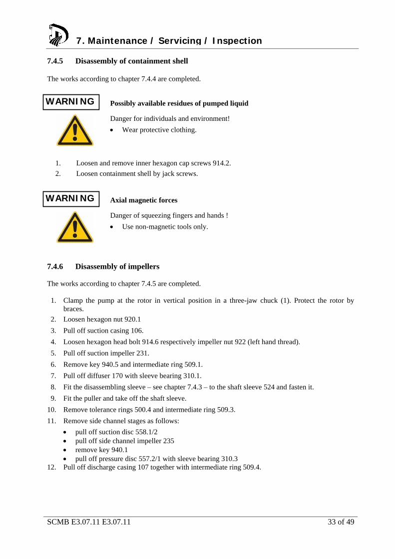
7.4.5 Disassembly of containment shell The works according to chapter 7.4.4 are completed.
Possibly available residues of pumped liquid
Danger for individuals and environment!
Wear protective clothing.
1. Loosen and remove inner hexagon cap screws 914.2.
2. Loosen containment shell by jack screws.
Axial magnetic forces
Danger of squeezing fingers and hands !
Use non-magnetic tools only.
7.4.6 Disassembly of impellers The works according to chapter 7.4.5 are completed. 1. Clamp the pump at the rotor in vertical position in a three-jaw chuck (1). Protect the rotor by
braces.
2. Loosen hexagon nut 920.1
3. Pull off suction casing 106.
4. Loosen hexagon head bolt 914.6 respectively impeller nut 922 (left hand thread).
5. Pull off suction impeller 231.
6. Remove key 940.5 and intermediate ring 509.1.
7. Pull off diffuser 170 with sleeve bearing 310.1.
8. Fit the disassembling sleeve – see chapter 7.4.3 – to the shaft sleeve 524 and fasten it.
9. Fit the puller and take off the shaft sleeve.
10. Remove tolerance rings 500.4 and intermediate ring 509.3.
11. Remove side channel stages as follows:
pull off suction disc 558.1/2 pull off side channel impeller 235 remove key 940.1 pull off pressure disc 557.2/1 with sleeve bearing 310.3
12. Pull off discharge casing 107 together with intermediate ring 509.4.
WARNING
7. Maintenance / Servicing / Inspection
WARNING
SCMB E3.07.11 E3.07.11 34 of 49
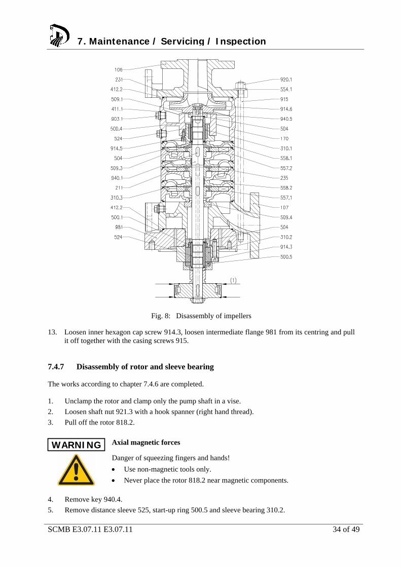
Fig. 8: Disassembly of impellers
13. Loosen inner hexagon cap screw 914.3, loosen intermediate flange 981 from its centring and pull it off together with the casing screws 915.
7.4.7 Disassembly of rotor and sleeve bearing The works according to chapter 7.4.6 are completed. 1. Unclamp the rotor and clamp only the pump shaft in a vise.
2. Loosen shaft nut 921.3 with a hook spanner (right hand thread).
3. Pull off the rotor 818.2.
Axial magnetic forces
Danger of squeezing fingers and hands!
Use non-magnetic tools only.
Never place the rotor 818.2 near magnetic components.
4. Remove key 940.4.
5. Remove distance sleeve 525, start-up ring 500.5 and sleeve bearing 310.2.
WARNING
7. Maintenance / Servicing / Inspection
SCMB E3.07.11 E3.07.11 35 of 49
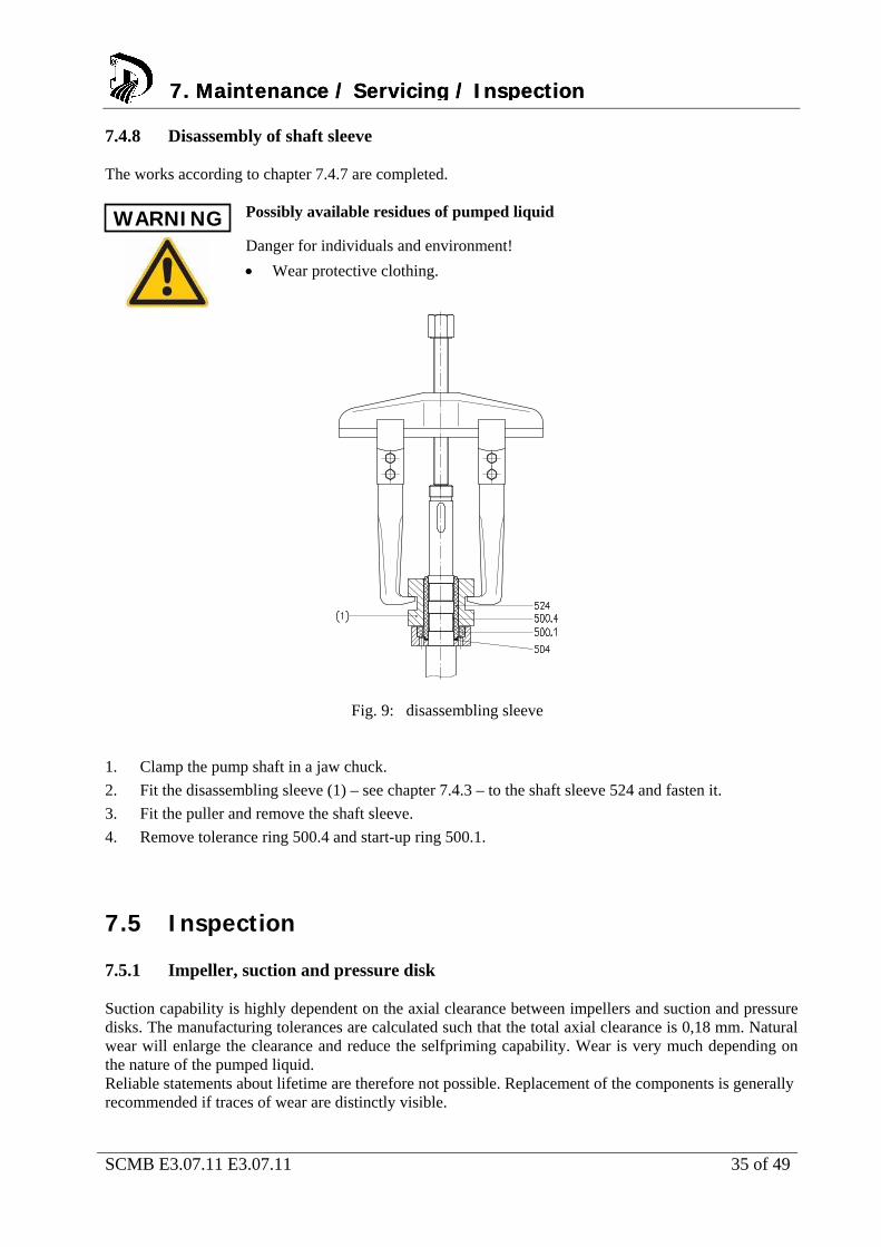
7.4.8 Disassembly of shaft sleeve The works according to chapter 7.4.7 are completed. Possibly available residues of pumped liquid
Danger for individuals and environment!
Wear protective clothing.
Fig. 9: disassembling sleeve 1. Clamp the pump shaft in a jaw chuck.
2. Fit the disassembling sleeve (1) – see chapter 7.4.3 – to the shaft sleeve 524 and fasten it.
3. Fit the puller and remove the shaft sleeve.
4. Remove tolerance ring 500.4 and start-up ring 500.1.
7.5 Inspection 7.5.1 Impeller, suction and pressure disk Suction capability is highly dependent on the axial clearance between impellers and suction and pressure disks. The manufacturing tolerances are calculated such that the total axial clearance is 0,18 mm. Natural wear will enlarge the clearance and reduce the selfpriming capability. Wear is very much depending on the nature of the pumped liquid. Reliable statements about lifetime are therefore not possible. Replacement of the components is generally recommended if traces of wear are distinctly visible.
WARNING
7. Maintenance / Servicing / Inspection7. Maintenance / Servicing / Inspection
SCMB E3.07.11 E3.07.11 36 of 49
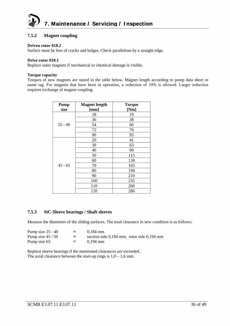
7.5.2 Magnet coupling Driven rotor 818.2 Surface must be free of cracks and bulges. Check parallelism by a straight edge. Drive rotor 818.1 Replace outer magnets if mechanical or chemical damage is visible. Torque capacity Torques of new magnets are stated in the table below. Magnet length according to pump data sheet or name tag. For magnets that have been in operation, a reduction of 10% is allowed. Larger reduction requires exchange of magnet coupling.
Pump size
Magnet length [mm]
Torque [Nm]
18 19 36 38 54 60 72 76
25 - 40
90 95 20 41 30 63 40 90 50 115 60 138 70 165 80 190 90 210
100 235 110 260
45 - 65
120 280 7.5.3 SiC-Sleeve bearings / Shaft sleeves Measure the diameters of the sliding surfaces. The total clearance in new condition is as follows: Pump size 25 - 40 = 0,184 mm Pump size 45 / 50 = suction side 0,184 mm; rotor side 0,194 mm Pump size 65 = 0,194 mm Replace sleeve bearings if the mentioned clearances are exceeded. The axial clearance between the start-up rings is 1,0 – 1,6 mm.
7. Maintenance / Servicing / Inspection7. Maintenance / Servicing / Inspection
SCMB E3.07.11 E3.07.11 37 of 49
7.6 Assembly of pump unit 7.6.1 General instructions Consider the safety instructions of chapter 7.1.
Consider the sectional drawings for assembly.
Use new gaskets and O-rings only.
Mount gaskets without lubricants.
Do not use assembling aid when mounting the gaskets. If necessary, use customary contact adhesive. Never use superglue.
Lubricate fittings and screw joints with graphite or similar lubricant. Lubricants must be compatible with the pumped liquid.
Tighten all screws properly. Consider chapter 7.7.
When mounting the shaft sleeve, use new tolerance rings only.
Hitting of rotor against containment shell or of containment shell against
coupling half through magnetic forces
Damage of magnets and bearing ! Risk of injury !
Strictly follow the assembling instructions.
Unprofessional assembly
Damage of the pump!
Assemble pumps / pump units under consideration of the general rules of engineering.
Only use original spare parts.
Improper mounting
Damage of outer magnet coupling !
Use guide rods.
The following must be checked prior to assembly: All dismantled parts are cleaned and checked for wear.
Damaged or worn out parts must be replaced by original spare parts.
All sealing surfaces are cleaned.
WARNING
ATTENTION
7. Maintenance / Servicing / Inspection
ATTENTION
SCMB E3.07.11 E3.07.11 38 of 49
7.6.2 Assembly of shaft sleeve 1. Slide the start-up ring and the new distance ring 504 up to the shaft collar.
2. Insert new tolerance rings 500.4 into the keyways.
3. Fit the disassembling sleeve – see chapter 7.4.3 – to the shaft sleeve and fasten it.
4. Spray the pump shaft in the area of the tolerance rings with graphite.
5. Press the pump shaft with a press- or drilling spindle into the shaft sleeve
7.6.3 Assembly of rotor and sleeve bearing The works according to chapter 7.6.2 are completed. 1. Slide on sleeve bearing 310.2, start-up ring 500.5 and new distance ring 504.
2. Slide on distance sleeve 525.
3. Insert key 940.4 and press it in by using a Knipex-plier wrench.
4. Slide on the rotor 818.2.
5. Tighten the shaft nut 921.3 by a hook spanner (right hand thread).
Axial magnetic force
Danger of squeezing fingers and hands!
Use non-magnetic tools.
Never place the rotor 818.2 near magnetic components.
7.6.4 Assembly of impellers The works according to chapter 7.6.3 are completed. 1. Clamp the rotor with pump shaft in a jaw chuck. Protect the rotor by braces.
2. Fit the intermediate flange 981 with casing screws 915.
3. Tighten inner hexagon cap screws 914.3.
4. Fit the discharge casing 107 together with intermediate ring 509.4. Do not forget the O-ring 412.2.
5. Assemble the side channel stages as follows: (Don’t forget O-rings 412.2)
Slide on the pressure disk 557.2/1
Insert the sleeve bearing 310.3
Insert key 940.1 and press it in by Knipex-plier wrench
Slide on the suction disk 558.1/2
7. Maintenance / Servicing / Inspection
WARNING
7. Maintenance / Servicing / Inspection7. Maintenance / Servicing / Inspection
SCMB E3.07.11 E3.07.11 39 of 49
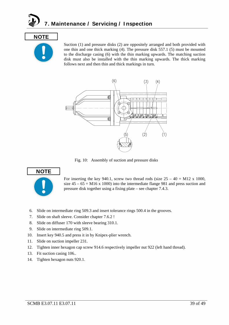
Suction (1) and pressure disks (2) are oppositely arranged and both provided with one thin and one thick marking (4). The pressure disk 557.1 (5) must be mounted to the discharge casing (6) with the thin marking upwards. The matching suction disk must also be installed with the thin marking upwards. The thick marking follows next and then thin and thick markings in turn.
Fig. 10: Assembly of suction and pressure disks
For inserting the key 940.1, screw two thread rods (size 25 – 40 = M12 x 1000, size 45 – 65 = M16 x 1000) into the intermediate flange 981 and press suction and pressure disk together using a fixing plate – see chapter 7.4.3.
6. Slide on intermediate ring 509.3 and insert tolerance rings 500.4 in the grooves.
7. Slide on shaft sleeve. Consider chapter 7.6.2 !
8. Slide on diffuser 170 with sleeve bearing 310.1.
9. Slide on intermediate ring 509.1.
10. Insert key 940.5 and press it in by Knipex-plier wrench.
11. Slide on suction impeller 231.
12. Tighten inner hexagon cap screw 914.6 respectively impeller nut 922 (left hand thread).
13. Fit suction casing 106..
14. Tighten hexagon nuts 920.1.
NOTE
NOTE
7. Maintenance / Servicing / Inspection
SCMB E3.07.11 E3.07.11 40 of 49
7.6.5 Assembly of containment shell The works according to chapter 7.6.4 are completed.
1. Fit containment shell. Use new gasket 400.4.
2. Tighten inner hexagon cap screws 914.2 by torque wrench.
7.6.6 Assembly of motor lantern / drive rotor 1. Fit the motor lantern 341 to the motor flange and tighten it with hexagon nuts 920.3.
2. Slide the drive rotor 818.1 onto the motor shaft.
3. Insert the intermediate ring 506 into the hub bore of the drive rotor and fasten it with inner
hexagon cap screw 914.11.
7.6.7 Motor assembly The works according to chapter 7.6.5 and 7.6.6 are completed. 1. Fit the pump unit to the motor lantern.
2. Tighten hexagon nuts 920.2 by torque wrench.
Tilting the pump
Squeezing of hands and feet!
Secure the pump by lifting or bracing.
Outer magnets are touching the containment shell
Damage of containment shell or outer magnets!
Always use guide rods.
7. Maintenance / Servicing / Inspection7. Maintenance / Servicing / Inspection
WARNING
ATTENTION
SCMB E3.07.11 E3.07.11 41 of 49
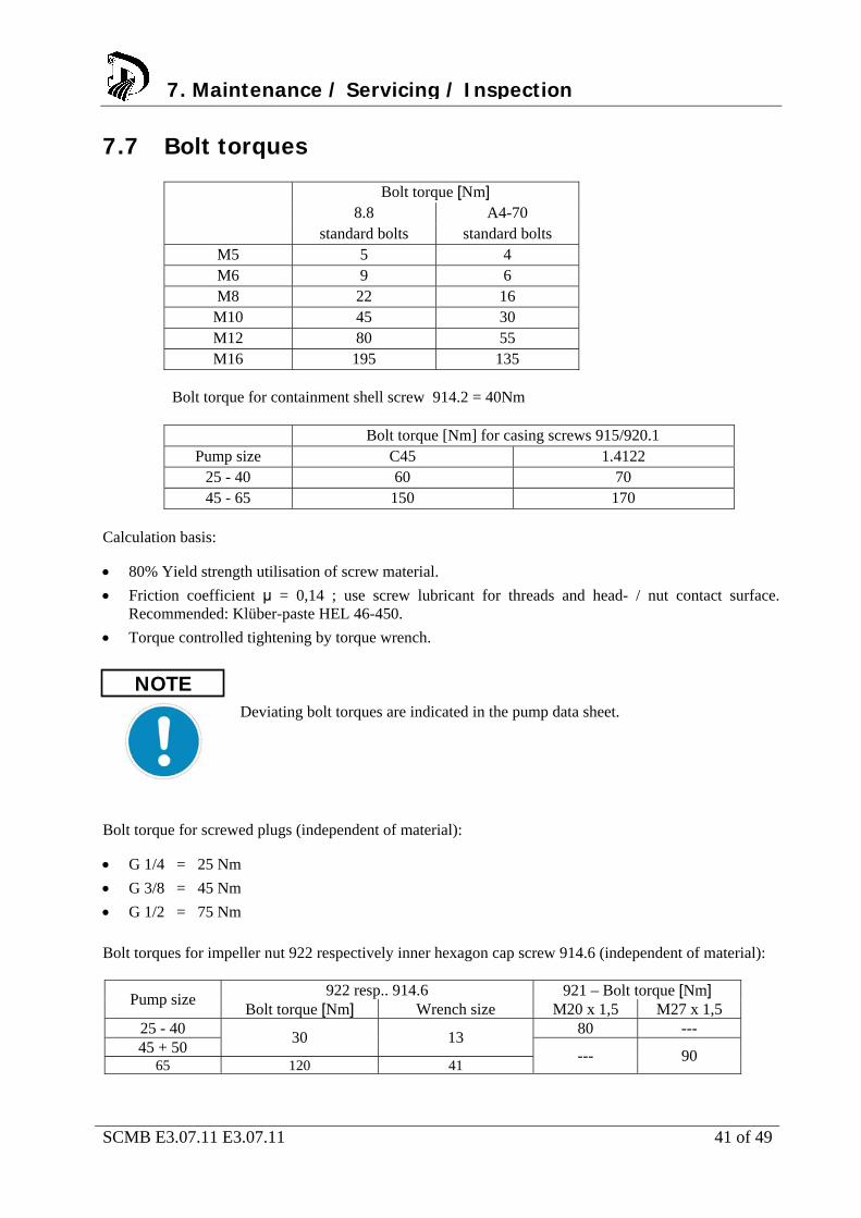
7.7 Bolt torques
Bolt torque [Nm] 8.8 A4-70
standard bolts standard bolts M5 5 4 M6 9 6 M8 22 16
M10 45 30 M12 80 55 M16 195 135
Bolt torque for containment shell screw 914.2 = 40Nm
Bolt torque [Nm] for casing screws 915/920.1 Pump size C45 1.4122
25 - 40 60 70 45 - 65 150 170
Calculation basis:
80% Yield strength utilisation of screw material.
Friction coefficient μ = 0,14 ; use screw lubricant for threads and head- / nut contact surface. Recommended: Klüber-paste HEL 46-450.
Torque controlled tightening by torque wrench.
Deviating bolt torques are indicated in the pump data sheet.
Bolt torque for screwed plugs (independent of material):
G 1/4 = 25 Nm
G 3/8 = 45 Nm
G 1/2 = 75 Nm
Bolt torques for impeller nut 922 respectively inner hexagon cap screw 914.6 (independent of material):
922 resp.. 914.6 921 – Bolt torque [Nm] Pump size
Bolt torque [Nm] Wrench size M20 x 1,5 M27 x 1,5 25 - 40 80 --- 45 + 50
30 13
65 120 41 --- 90
7. Maintenance / Servicing / Inspection
NOTE
SCMB E3.07.11 E3.07.11 42 of 49
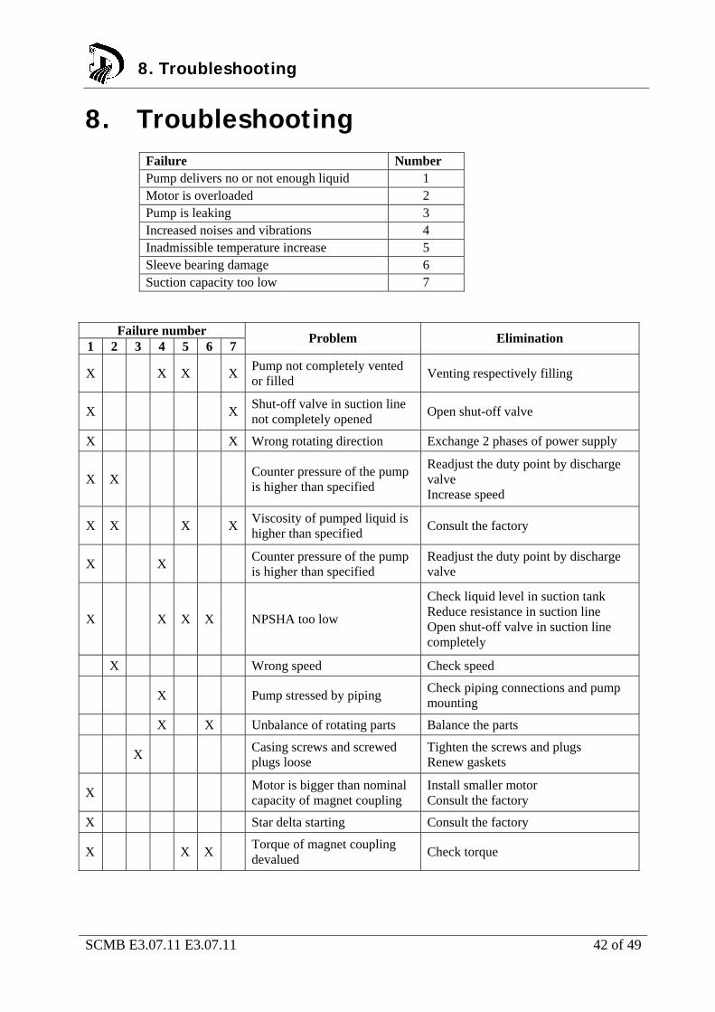
8. Troubleshooting
Failure Number Pump delivers no or not enough liquid 1 Motor is overloaded 2 Pump is leaking 3 Increased noises and vibrations 4 Inadmissible temperature increase 5 Sleeve bearing damage 6 Suction capacity too low 7
Failure number 1 2 3 4 5 6 7
Problem Elimination
X X X X Pump not completely vented or filled
Venting respectively filling
X X Shut-off valve in suction line not completely opened
Open shut-off valve
X X Wrong rotating direction Exchange 2 phases of power supply
X X Counter pressure of the pump is higher than specified
Readjust the duty point by discharge valve Increase speed
X X X X Viscosity of pumped liquid is higher than specified
Consult the factory
X X Counter pressure of the pump is higher than specified
Readjust the duty point by discharge valve
X X X X NPSHA too low
Check liquid level in suction tank Reduce resistance in suction line Open shut-off valve in suction line completely
X Wrong speed Check speed
X Pump stressed by piping Check piping connections and pump mounting
X X Unbalance of rotating parts Balance the parts
X Casing screws and screwed plugs loose
Tighten the screws and plugs Renew gaskets
X Motor is bigger than nominal capacity of magnet coupling
Install smaller motor Consult the factory
X Star delta starting Consult the factory
X X X Torque of magnet coupling devalued
Check torque
8. Troubleshooting
SCMB E3.07.11 E3.07.11 43 of 49
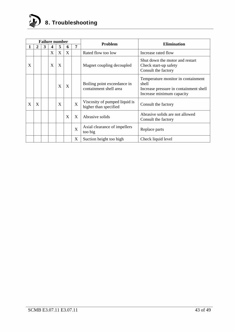
Failure number
1 2 3 4 5 6 7 Problem Elimination
X X X Rated flow too low Increase rated flow
X X X Magnet coupling decoupled Shut down the motor and restart Check start-up safety Consult the factory
X X Boiling point exceedance in containment shell area
Temperature monitor in containment shell Increase pressure in containment shell Increase minimum capacity
X X X X Viscosity of pumped liquid is higher than specified
Consult the factory
X X Abrasive solids Abrasive solids are not allowed Consult the factory
X Axial clearance of impellers too big
Replace parts
X Suction height too high Check liquid level
8. Troubleshooting

SCMB E3.07.11 E3.07.11 44 of 49
9. Interchangeability
9. Interchangeability
SCMB E3.07.11 E3.07.11 45 of 49
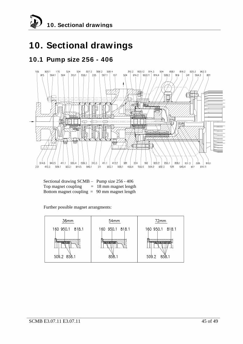
10. Sectional drawings 10.1 Pump size 256 - 406
Sectional drawing SCMB – Pump size 256 - 406 Top magnet coupling = 18 mm magnet length Bottom magnet coupling = 90 mm magnet length Further possible magnet arrangments:
10. Sectional drawings

SCMB E3.07.11 E3.07.11 46 of 49
10.2 Pump size 456 + 506
Sectional drawing SCMB – Pump size 456 - 506 Top magnet coupling = 20 mm magnet length Bottom magnet coupling = 120 mm magnet length Further possible magnet arrangments:
10. Sectional drawings
SCMB E3.07.11 E3.07.11 47 of 49
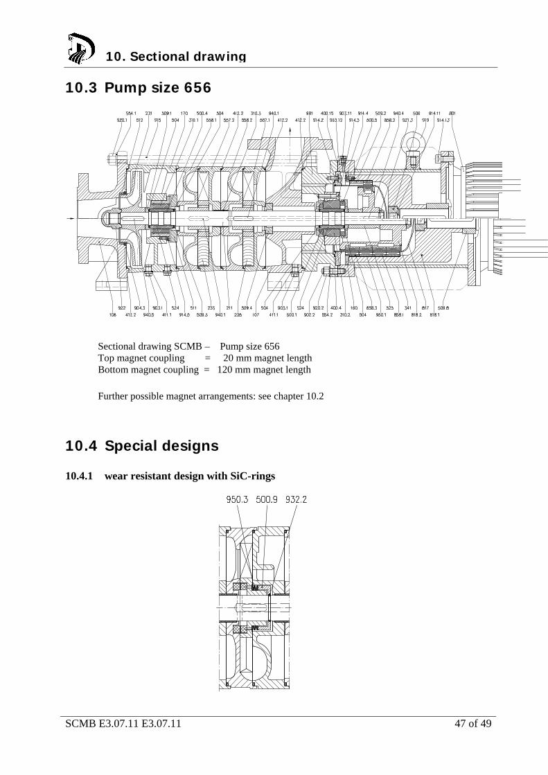
10.3 Pump size 656
Sectional drawing SCMB – Pump size 656 Top magnet coupling = 20 mm magnet length Bottom magnet coupling = 120 mm magnet length
Further possible magnet arrangements: see chapter 10.2
10.4 Special designs 10.4.1 wear resistant design with SiC-rings
10. Sectional drawing
SCMB E3.07.11 E3.07.11 48 of 49
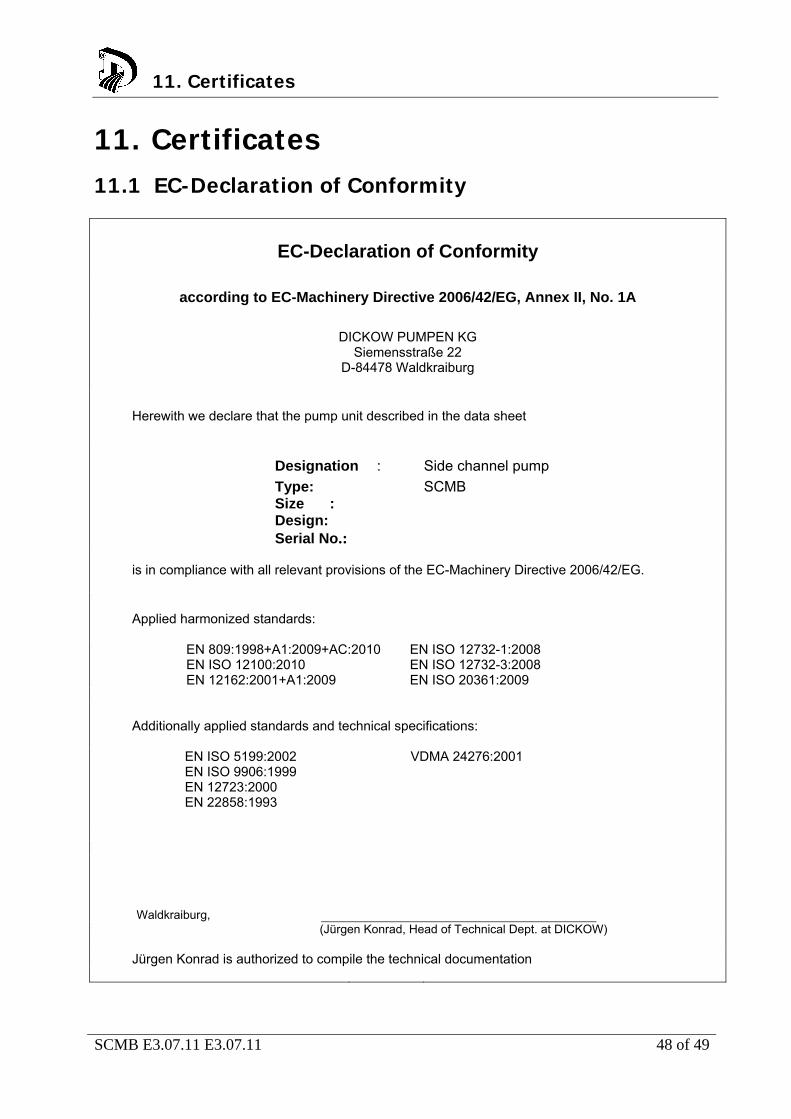
11. Certificates 11.1 EC-Declaration of Conformity
EC-Declaration of Conformity
according to EC-Machinery Directive 2006/42/EG, Annex II, No. 1A
DICKOW PUMPEN KG
Siemensstraße 22 D-84478 Waldkraiburg
Herewith we declare that the pump unit described in the data sheet
Designation : Side channel pump
Type: SCMB Size : Design: Serial No.:
is in compliance with all relevant provisions of the EC-Machinery Directive 2006/42/EG.
Applied harmonized standards: EN 809:1998+A1:2009+AC:2010
EN ISO 12100:2010 EN 12162:2001+A1:2009
EN ISO 12732-1:2008 EN ISO 12732-3:2008 EN ISO 20361:2009
Additionally applied standards and technical specifications:
EN ISO 5199:2002 EN ISO 9906:1999 EN 12723:2000 EN 22858:1993
VDMA 24276:2001
Waldkraiburg,
(Jürgen Konrad, Head of Technical Dept. at DICKOW) Jürgen Konrad is authorized to compile the technical documentation
11. Certificates
SCMB E3.07.11 E3.07.11 49 of 49
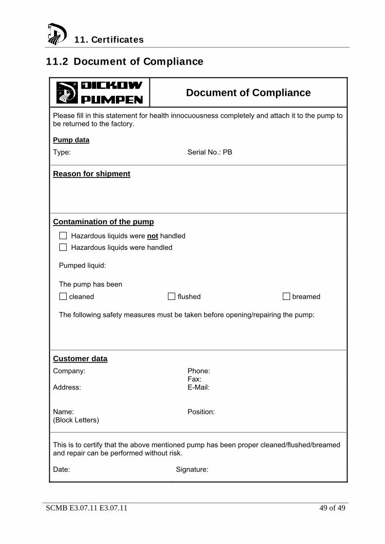
11.2 Document of Compliance
Document of Compliance
Please fill in this statement for health innocuousness completely and attach it to the pump to be returned to the factory.
Pump data
Type: Serial No.: PB
Reason for shipment
Contamination of the pump
Hazardous liquids were not handled
Hazardous liquids were handled Pumped liquid:
The pump has been
cleaned flushed breamed
The following safety measures must be taken before opening/repairing the pump:
Customer data
Company: Phone:
Fax:
Address: E-Mail:
Name: Position: (Block Letters)
This is to certify that the above mentioned pump has been proper cleaned/flushed/breamed and repair can be performed without risk. Date: Signature:
11. Certificates