Embed Size (px)
Citation preview
DIDACTIC MICROCOMPUTER ZD537
Instruction for laboratory exercises
Kazimierz Kapłon
Jacek Majewski
Jarosław Sugier
Part I: Hardware description
Part II: Program description
Appendix: 1. ZD537 Monitor
2. Test program
3. Didactic program
4. Boards descriptions
Institute of Computer Engineering, Control and Robotics
Wroclaw University of Technology, 2003
ZD537 Didactic Microcomputer
1
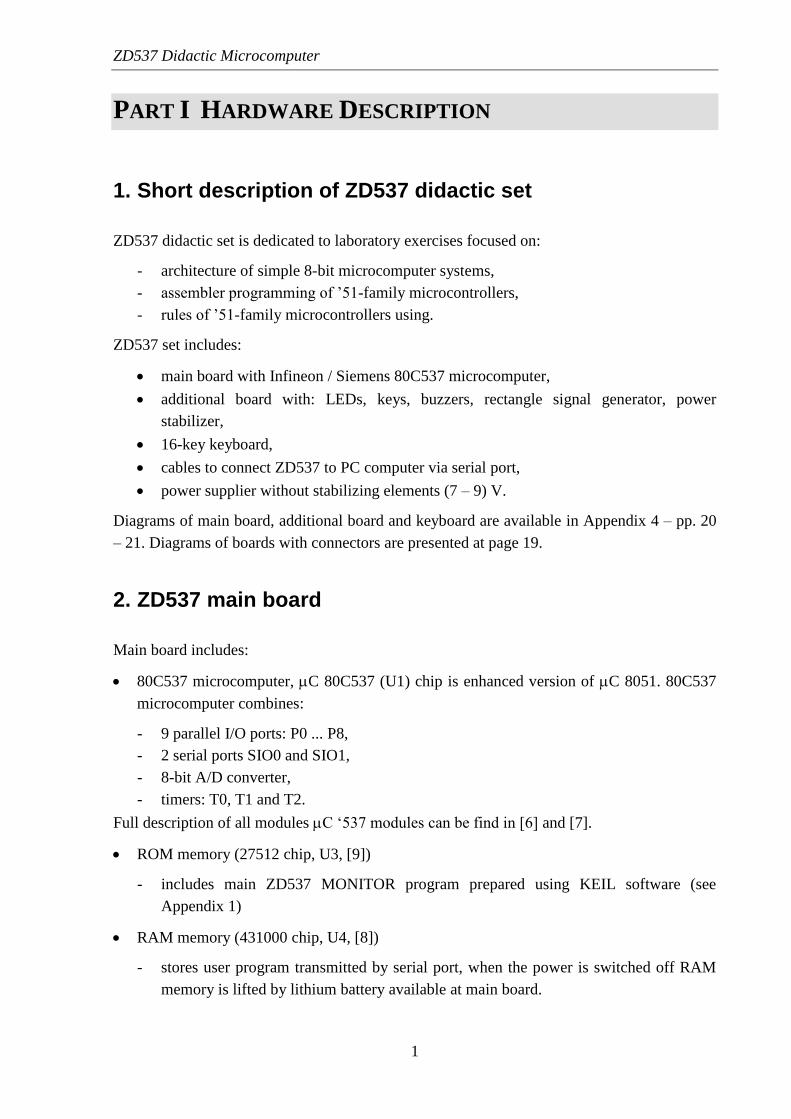
PART I HARDWARE DESCRIPTION
1. Short description of ZD537 didactic set
ZD537 didactic set is dedicated to laboratory exercises focused on:
- architecture of simple 8-bit microcomputer systems,
- assembler programming of ’51-family microcontrollers,
- rules of ’51-family microcontrollers using.
ZD537 set includes:
main board with Infineon / Siemens 80C537 microcomputer,
additional board with: LEDs, keys, buzzers, rectangle signal generator, power
stabilizer,
16-key keyboard,
cables to connect ZD537 to PC computer via serial port,
power supplier without stabilizing elements (7 – 9) V.
Diagrams of main board, additional board and keyboard are available in Appendix 4 – pp. 20
– 21. Diagrams of boards with connectors are presented at page 19.
2. ZD537 main board
Main board includes:
80C537 microcomputer, C 80C537 (U1) chip is enhanced version of C 8051. 80C537
microcomputer combines:
- 9 parallel I/O ports: P0 ... P8,
- 2 serial ports SIO0 and SIO1,
- 8-bit A/D converter,
- timers: T0, T1 and T2.
Full description of all modules C ‘537 modules can be find in [6] and [7].
ROM memory (27512 chip, U3, [9])
- includes main ZD537 MONITOR program prepared using KEIL software (see
Appendix 1)
RAM memory (431000 chip, U4, [8])
- stores user program transmitted by serial port, when the power is switched off RAM
memory is lifted by lithium battery available at main board.
ZD537 Didactic Microcomputer
2
Serial ports SIO0 and SIO1 connectors:
- serial ports SIO0 and SIO1 of C ‘537 are connected to DB9 connector by voltage
converter chip MAX 232 (U9, [13]) – transmission according to RS232. SIO0/SIO1
selection is realised by switch located near DB9 connector. SIO1 transmission can be
done also according to RS485. It is necessary to set U10 chip ([15]) and to remove
Z10 strap. Transmission according to RS485 over 10m ( 1200m) requires special
terminators.
RTC (Real Time Clock) - timer/calendar chip (RTC-72421, U7, [11])
- RTC registers are available in XRAM at FF0xh addresses (Fig. 1). RTC is lifted by
lithium battery.
Chip MAX691 (U8, [12]) – power guard, RESET signal generation, battery lifting
switching.
SW2 switch: system RESET.
LCD module
- 2 lines, 16 character in each line,
- LCD display fixed to main board and connected by LCD1 connector,
- LCD driver’s registers available in XRAM at FF2xh addresses (Fig.1, HD44780 chip
driver description – [10]).
Matrix 16-key keyboard
- connected by JP1 connector
- available by scanning method
- keyboard interruptions available with additional chip U11.
8-switch module SW1
- available via P7 parallel port
Caution: P7 parallel port is also used for keyboard, so when keyboard is in use set SW1
switches to OFF!
Additional elements of main board available via P6 parallel port:
- P6.4 – piezoelectricity converter with 1 kHz generator
- P6.0 – red LED (D3)
- P6.6 – relay’s connectors available at ZS11, ZS12 connectors
JP9/JP11 connector – auxiliary device driven via P4 parallel port.
A/D converter (8 channels)
- can be driven by SW1 connectors (0V or 5V), continuous changes from 0V to 5V is
available if potentiometers are connected to JP10.
ZD537 Didactic Microcomputer
3
GAL chips (U5, U6, type: 16V8)
decoders of memory addresses and devices into XRAM
3 modes of main board settings:
a) MONITOR mode: Z7=OFF Z8=OFF (upper position of switch) - MONITOR 537
program working;
b) RAM mode: Z7=OFF Z8=ON (lower position of switch) - user program working
stored in RAM memory;
c) ROM mode: Z7=ON Z8=OFF/ON (not important) - program stored in ROM
memory working.
JP5, JP6 connectors – power from additional board supplies main board
3. ZD537 additional board
Additional board is connected to auxiliary power supplier without stabilizing elements (7-
9)V. The board includes stabilizer 7805 (IC1). The ZD537 main board is supplied by
stabilized power by JP5&JP6 connectors. 8 LEDs are connected using the same connector,
they allow to observe lines of P1 parallel port from C ‘537.
The rectangle signal generator (NE555 chip) is connected to line P1.7. Available
frequencies are from 1 Hz to 30 Hz. The signal generated by NE555 we can disconnect by
taking off J1 strap. R16 resistor is a guard of simultaneous generation by NE555 and C’537.
Four lines of P3 parallel port (P3.2, P3.3, P3.4 i P3.5) are supported by LEDs and buttons
which can be used for signal generation – interrupts generations. Others bits of P3 are used as
system signals \RD, \WR and to serve serial port signals: RxD and TxD. This way they are
not available for ZD537 user.
Piezoelectric, electro-acoustic converter is connected to line P3.2. The device is prepared
to generate acoustic signals by user programs.
4. Keyboard
Matrix keyboard is connected to main board by JP1 connector. The keyboard includes 4
rows by 4 buttons (Appendix 4, p. 21). The keyboard ought to be read by scanning method: it
is necessary to set lines (P5.4 – P5.7) of P5 parallel port by logic zero and read bits P7.3 –
P7.0.
If chip U11 is present it is possible to execute keyboard interrupts at line P1.4 (auxiliary
interrupt of ‘537 processor). When the keyboard is in use SW1 switches have to be OFF!
ZD537 Didactic Microcomputer
4
5. Cables for serial port transmission
Serial ports signals SIO0 and SIO1 are available at JP2 and DB9 connectors (see p. 21).
The switch at the back side of the ZD537 allows to choose which port: SIO0 or SIO1 is
connected do DB9 and guarantees the communication C – PC. Red or black point shows
SIO0.
6. Map of ZD537 ports
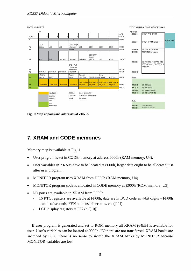
Map of ZD537 ports you can see at Fig. 1.
– P0, P2 and partially P3 (lines P3.6 and P3.7) are the system buses and are not available for
users.
– LEDs are connected to P1. Using J1 strap NE555 as rectangle signal generator can be
connected to P1.7. If chip U11 is present it is possible to execute keyboard interrupts at line
P1.4
– LEDs and buttons are connected to P3.5 ... P3.2. Piezoelectric buzzer is connected to line
P3.2.
– P4 are available for the user at JP9/JP11 connector.
– The older part of P5 is connected to the keyboard. The row-driving is realised by younger
part of P7. All lines of P7 are connected to DIP SWITCH SW1. When the keyboard is in
use SW1 switches have to be OFF!
– P6 drives: red LED D3 (line P6.0) at main board, relay REL1 and PC1-buzzer which
generates 1 kHz signal. P6.6 is responsible for direction of RS485 transmission. RS485
lines are combined to SIO1. P6.7 switches the banks of XRAM memory.
CAUTION:
– P6, P7 and P8 – are available as bytes only, are not available by bits,
– P1, P3, P4, P5 – are available as bytes, are available by bits also,
– P7 and P8 – are read-only (A/D converter ports).
ZD537 Didactic Microcomputer
5
7. XRAM and CODE memories
Memory map is available at Fig. 1.
User program is set in CODE memory at address 0000h (RAM memory, U4).
User variables in XRAM have to be located at 8000h, larger data ought to be allocated just
after user program.
MONITOR program uses XRAM from DF00h (RAM memory, U4).
MONITOR program code is allocated in CODE memory at E000h (ROM memory, U3)
I/O ports are available in XRAM from FF00h:
- 16 RTC registers are available at FF00h, data are in BCD code as 4-bit digits – FF00h
– units of seconds, FF01h – tens of seconds, etc.([11]).
- LCD display registers at FF2xh ([10]).
If user program is generated and set to ROM memory all XRAM (64kB) is available for
user. User’s variables can be located at 0000h. I/O ports are not transferred. XRAM banks are
switched by P6.7. There is no sense to switch the XRAM banks by MONITOR because
MONITOR variables are lost.
ZD537 I/O PORTS ZD537 XRAM & CODE MEMORY MAP
bit
PORT 7 6 5 4 3 2 1 0
SFR
ADDR
0000H USER PROGRAM
USER areaP0 D7...0 080H
P1
LED/
555out LED LED interrupt LED LED LED LED 090H
8000H USER XRAM variables
P2 ADDR 0A0H DF00H MONITOR variables
P3 \RD \WR LED-BUT LED-BUT LED-BUT
LED-BUT/
buzzer
piezzo Tx0 Rx0 0B0H
E000H MONITOR program
P4
JP9-JP10
connector/
extra leds 0E8H
FF00H I/O PORTS in XRAM: RTC
(FF0XH) and LCD (FF2XH)
registers
P5 FFFFH
P6
X0 RAM
switch Relay
Buzzer
1kHz
RS485
direction Tx1/ RS485
Rx1/
RS485 RED led 0FAH LCD
P7 DIP switch DIP switch DIP switch DIP switch
DIP switch/
keyb in
DIP switch/
keyb in
DIP switch/
keyb in
DIP switch/
keyb in 0DBH FF2EH LCD Status
P8 0DDH FF2CH LCD Control
FF2FH LCD Data READ
input port 555out pulse generator FF2DH LCD Data WRITE
external
memory
bus
LED-BUT LED diode and button
RTC
byte
adresable
keyb keyboard
FF00H units of seconds
FF01H decimals of seconds
ADDRES
Fig. 1: Map of ports and addresses of ZD537.

ZD537 Didactic Microcomputer
6
PART II SOFTWARE DESCRIPTION
8. Communication with PC computer
Collaboration between ZD537 and PC computer is realised by Keil Software GmbH
(http://www.keil.com): integrated environment Vision or simple text monitor mon51.exe.
The communication is realised by serial port. To start transmission it is necessary to:
a) set DB9 into SIO0 (switch „turned into red or black point”),
b) realize RESET in MONITOR mode (switch Z8 released MONITOR ZD 537 visible at
LCD display).
Communication is realised by monitor generated using Keil devices and stored in EPROM
(Appendix 1, [14]).
9. Vision 2 environment
Vision software is an Integrated Development Environment (IDE), which offers all devices
necessary during program creation for ’51 microcomputer. It is possible in one application: to
edit source code, to compile, to link, to send the ready to use program to ZD537. Then it is
possible to start the user program: also step-tracking, you can observe the actual data in
registers, ports, memory, etc.
There is a limit of 2kB of ready to use code of user program.
INFO ABOUT SOFTWARE
Vision software is a very sophisticated product. There is help option available:
Books (use Help Open Books Window). The most valuable are the following files:
Windows help: „uVision User’s Guide”;
„Getting Started with Vision2”, file GS51.PDF;
„Macro Assembler and Utilities”, file A51.PDF.
PDF file are stored in: Keil\C51\HLP\.
Below you can find the steps of simple program creation.

ZD537 Didactic Microcomputer
7
NEW PROJECT CREATION
1) Menu: Project New project...
Project files have extension: .uv2.
Make project in new folder (in the dialog box „Create new project” you can create new
folders).
In dialog box Select device for target‘Target1’ find proper chip (Infineon SAB
80C537).
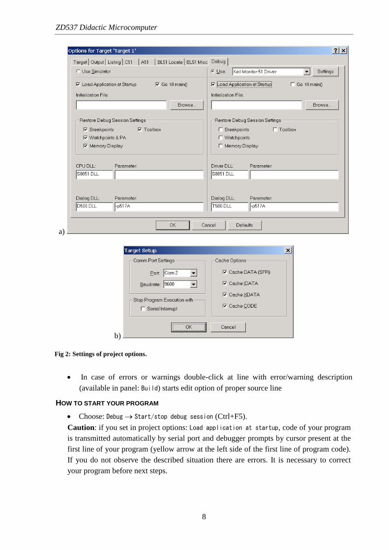
2) Options for project: Project Options for target‘Target1’ (see Fig. 2)
Label Target: set frequency Xtal 12 MHz.
Label Output: check if selected filed: Debug information.
Label Debug: choose: Use: Keil Monitor-51 Driver and choose Load application at
startup.
Caution: it is possible to start program using simulator (without ZD537). If you want to
make it choose in label Debug (Fig. 2a): Use Simulator.
Button Settings (Fig. 2b): Port Com 1 (used in PC computer for communication with
ZD537), Baudrate 9600.
Caution: if you use SIO0 in your program there are problems with transmission realised
by Keil monitor, clear in that case all options Cache in settings at Fig. 2b.
3) Source file creation
Choose File New, use extension a51 or asm for assembler files.
Add your file to project: choose Project Targets, Groups, Files..., label Groups /
Add files, choose Source Group 1, button Add files to group..., choose your source
file.
COMPILER AND LINKER
Choose: Project Build target (F7) or Project Rebuild all targets.
ZD537 Didactic Microcomputer
8
In case of errors or warnings double-click at line with error/warning description
(available in panel: Build) starts edit option of proper source line
HOW TO START YOUR PROGRAM
Choose: Debug Start/stop debug session (Ctrl+F5).
Caution: if you set in project options: Load application at startup, code of your program
is transmitted automatically by serial port and debugger prompts by cursor present at the
first line of your program (yellow arrow at the left side of the first line of program code).
If you do not observe the described situation there are errors. It is necessary to correct
your program before next steps.
a)
b)
Fig 2: Settings of project options.

ZD537 Didactic Microcomputer
9
Step by step execution:
Debug Go (F5)
Debug Step (F11)
Debug Step over (F10)
Debug Run to cursor line (Ctrl+F10)
Variables watching (defined in IRAM by assembler DATA option): choose View
Watch & call stack window.
Memory watching: View Memory window.
Different parts of memory you can display as follow:
B:0xXX - IRAM memory, bit addressing
C:0xXXXX - CODE memory
D:0xXX - IRAM memory direct addressing
I:0xXX - IRAM memory indirect addressing
X:0xXXXX - XRAM memory
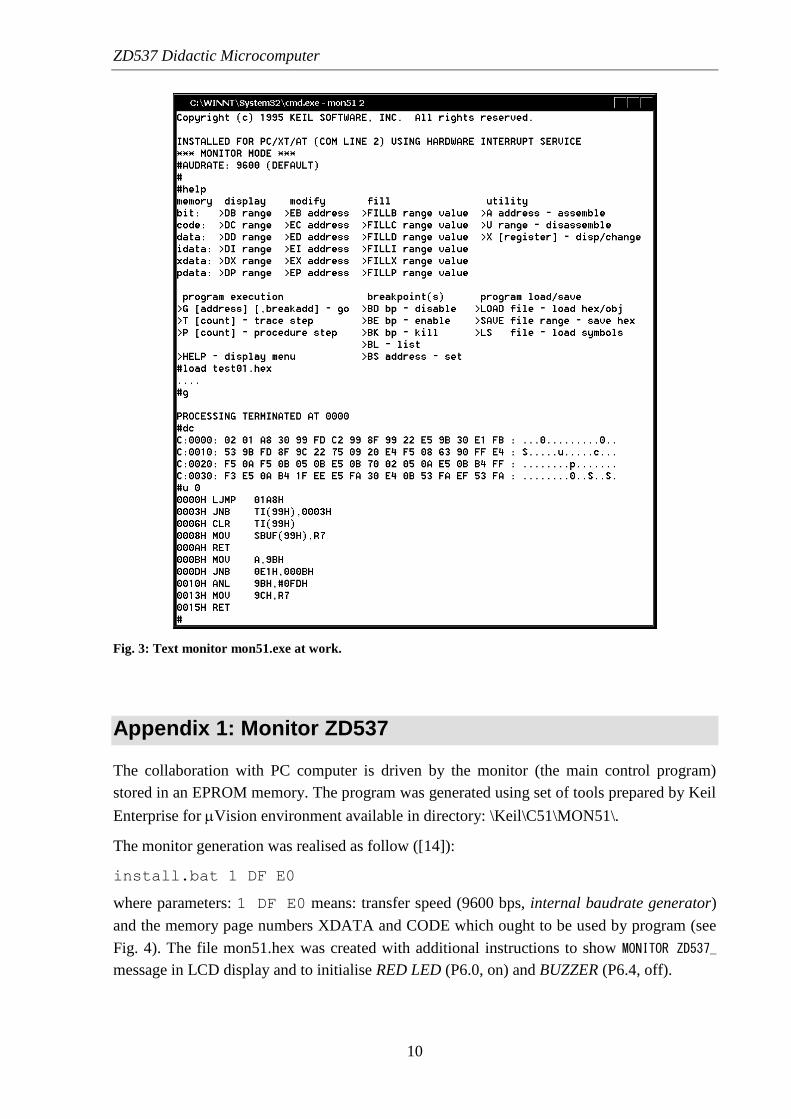
10. Text monitor MON51.EXE
MON51.EXE is a simple text program to monitor the state of ’51 sets collaborating with PC
computers based on Keil protocol.
To start it type:
mon51.exe 2
where parameter 2 defines the number of Com port. The end by F1 key.
The monitor session is presented in Fig. 3. A ‘#” symbol is a prompt. The first operation:
help presents the monitor functions. The instruction: load tes01.hex loads the ready to
use test program. The file test01.hex (created using Vision environment for example)
ought to be stored in the same directory as monitor mon51.exe. The g (go) operation starts
the loaded program. The text PROCESS TERMINATED AT is the result of using RESET key
when the program runs. The dc (display code) operation shows in byte-mode the actual state
of CODE memory, the u (unassemble) operation the same part of memory after
disassembling.
The ready to use test program to verify if parts of microcomputer are OK is described in
Appendix 2.
ZD537 Didactic Microcomputer
10
Appendix 1: Monitor ZD537
The collaboration with PC computer is driven by the monitor (the main control program)
stored in an EPROM memory. The program was generated using set of tools prepared by Keil
Enterprise for Vision environment available in directory: \Keil\C51\MON51\.
The monitor generation was realised as follow ([14]):
install.bat 1 DF E0
where parameters: 1 DF E0 means: transfer speed (9600 bps, internal baudrate generator)
and the memory page numbers XDATA and CODE which ought to be used by program (see
Fig. 4). The file mon51.hex was created with additional instructions to show MONITOR ZD537_
message in LCD display and to initialise RED LED (P6.0, on) and BUZZER (P6.4, off).
Fig. 3: Text monitor mon51.exe at work.
ZD537 Didactic Microcomputer
11
Caution: SIO0 channel is already used for communication matters of the monitor, so there is
no chance to observe its state in the user’s program. It is possible to generate the monitor
program using SIO1 channel (install.bat 3 DF E0) and to connect two cables to PC
computer (Com1 and Com2). This way is possible to trace SIO0 channel by SIO1 channel.
Appendix 2: Test program TEST01.HEX
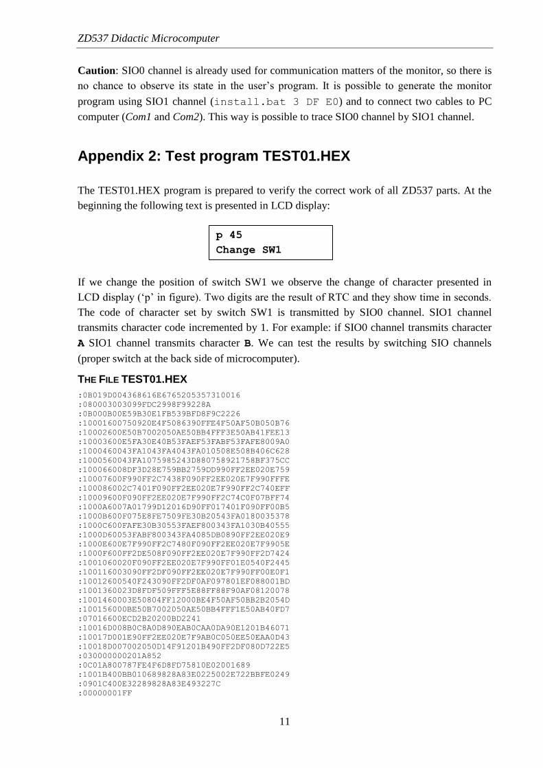
The TEST01.HEX program is prepared to verify the correct work of all ZD537 parts. At the
beginning the following text is presented in LCD display:
If we change the position of switch SW1 we observe the change of character presented in
LCD display (‘p’ in figure). Two digits are the result of RTC and they show time in seconds.
The code of character set by switch SW1 is transmitted by SIO0 channel. SIO1 channel
transmits character code incremented by 1. For example: if SIO0 channel transmits character
A SIO1 channel transmits character B. We can test the results by switching SIO channels
(proper switch at the back side of microcomputer).
THE FILE TEST01.HEX
:0B019D004368616E6765205357310016
:080003003099FDC2998F99228A
:0B000B00E59B30E1FB539BFD8F9C2226
:10001600750920E4F5086390FFE4F50AF50B050B76
:10002600E50B7002050AE50BB4FFF3E50AB41FEE13
:10003600E5FA30E40B53FAEF53FABF53FAFE8009A0
:1000460043FA1043FA4043FA010508E508B406C628
:1000560043FA1075985243D880758921758BF375CC
:100066008DF3D28E759BB2759DD990FF2EE020E759
:10007600F990FF2C7438F090FF2EE020E7F990FFFE
:100086002C7401F090FF2EE020E7F990FF2C740EFF
:10009600F090FF2EE020E7F990FF2C74C0F07BFF74
:1000A6007A01799D12016D90FF017401F090FF00B5
:1000B600F075E8FE7509FE30B20543FA0180035378
:1000C600FAFE30B30553FAEF800343FA1030B40555
:1000D60053FABF800343FA4085DB0890FF2EE020E9
:1000E600E7F990FF2C7480F090FF2EE020E7F9905E
:1000F600FF2DE508F090FF2EE020E7F990FF2D7424
:1001060020F090FF2EE020E7F990FF01E0540F2445
:100116003090FF2DF090FF2EE020E7F990FF00E0F1
:10012600540F243090FF2DF0AF097801EF088001BD
:1001360023D8FDF509FFF5E88FF88F90AF08120078
:1001460003E50804FF12000BE4F50AF50BB2B2054D
:100156000BE50B7002050AE50BB4FFF1E50AB40FD7
:07016600ECD2B20200BD2241
:10016D008B0C8A0D890EAB0CAA0DA90E1201B46071
:10017D001E90FF2EE020E7F9AB0C050EE50EAA0D43
:10018D007002050D14F91201B490FF2DF080D722E5
:030000000201A852
:0C01A800787FE4F6D8FD75810E02001689
:1001B400BB010689828A83E0225002E722BBFE0249
:0901C400E32289828A83E493227C
:00000001FF
p 45
Change SW1

ZD537 Didactic Microcomputer
12
Additionally, the test program switch on LEDs connected to P1 and P3 ports (ring-counter
driven by zero), the buzzer connected to P3.2. generates sound. If we push the key connected
to P3.2 the sound ends. The key connected to P3.3 switched off the buzzer. The key
connected to P3.4 is responsible for flip-flop.
If SW1 is switched OFF we can test the keyboard. The key pressing generates the special
characters in LCD display and send the characters to SIO0 channel.
Appendix 3: Didactic program
This part of the document presents the TEST program for didactic set ZD537. All modules of
the example are written in assembler and are prepared based on template.a51 program by
KEIL (see directory: \keil62\c51\asm\template.a51). This is strongly recommended style for
assembler programs. The program modules show how to operate with serial transfer via SIO0
and SIO1 channels, LCD display and clock/calendar module called RTC.
The presented modules are the basic examples and they are not finished. The student task is to
use the example to prepare their programs in the same style. It is very good idea to create the
programs as multi modules structures using segments, macros, etc. The laboratory exercises
are not only focused on ’51 processors’ set of instructions, but to learn about assembler’s
pseudo operations.
Below you can find the modules with comments. The comments are related to numbers of
rows and are signed by #nn, where nn – is the row number.
ZD537 Didactic Microcomputer
13
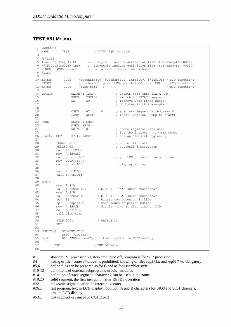
TEST.A51 MODULE
1 $NOMOD51
2 NAME TEST ; ZD537 ASM tutorial
3
4 $NOLIST
5 #include <reg517.h> // C-style include definition file (for example, 80517)
6 ;$INCLUDE(reg517.inc) ; asm-style include definition file (for example, 80517)
7 $INCLUDE(ZD537.inc) ; definition file for ZD537 board
8 $LIST
9
10 EXTRN CODE (putcharSIO0, putcharSIO1, initSIO0, initSIO1) ; SIO functions
11 EXTRN CODE (putcharLCD, putstrLCD, putctrlLCD, initLCD) ; LCD functions
12 EXTRN CODE (disp_time ) ; RTC functions
13
14 ?STACK SEGMENT IDATA ; ?STACK goes into IDATA RAM.
15 RSEG ?STACK ; switch to ?STACK segment.
16 DS 50 ; reserve your stack space
17 ; 50 bytes in this example.
18
19 CSEG AT 0 ; absolute Segment at Address 0
20 LJMP start ; reset location (jump to start)
21
22 PROG SEGMENT CODE
23 RSEG PROG
24 USING 0 ; state register_bank used
25 ; for the following program code.
26 Start: MOV SP,#?STACK-1 ; assign stack at beginning
27
28 BUZZER_OFF; ; Buzzer 1kHz off
29 REDLED_ON; ; optional instruction
30 call initLCD ;
31 mov A,#HOME2
32 call putctrlLCD ; put LCD cursor to second line
33 MOV DPTR,#text
34 call putstrLCD ; display string
35
36 call initSIO0;
37 call initSIO1;
38
39 ?C01:
40 mov A,#'A'
41 call putcharSIO0 ; SIO0 <-- 'A' (send charactear)
42 mov A,#'B'
43 call putcharSIO1 ; SIO0 <-- 'B' (send charactear)
44 inc P1 ; binary counteron on P1 LEDs
45 cpl BUZZpiezzo ; make sound on piezzo buzzer
46 mov A,#HOME ; display time at fist line on LCD
47 call putctrlLCD
48 call disp_time
49
50 SJMP ?C01 ; while(1);
51 RET
52
53 ?CO?TEXT SEGMENT CODE
54 RSEG ?CO?TEXT
55 text: DB "ZD537 test",00 ; text located in CODE memory
56
57 END ; END OF main
58
#1 standard ’51 processor registers are turned off, program is for ‘517 processor.
#4 listing of file header (include) is prohibited, knowing of files reg571.h and reg517.inc obligatory!
#5,6 define files can be prepared as for C and as for assembler style
#10-12 definitions of external subprograms in other modules
#14 definition of stack segment, character ? can be used in the name
#19,20 solid segment, the first instruction after RESET operation
#22 moveable segment, after the interrupt vectors
#26... test program, text in LCD display, loop with A and B characters for SIO0 and SIO1 channels,
time in LCD display
#53... text segment organised in CODE part
ZD537 Didactic Microcomputer
14
ZD537.INC MODULE
1 ; ZD537 BOARD: macros & definitions ----------------------
2
3 NE555 BIT P1.7
4 BUZZpiezzo BIT P3.2
5
6 ;P6 port bit definitions
7 BUZZ1kHz equ 00010000B
8 REDLED equ 00000001B
9 RELAY equ 01000000B
10
11 BUZZER_OFF MACRO
12 ANL P6,#(NOT BUZZ1kHz)
13 ENDM
14
15 BUZZER_ON MACRO
16 ORL P6,# BUZZ1kHz
17 ENDM
18
19 BUZZER_TOGGLE MACRO
20 XRL P6,# BUZZ1kHz
21 ENDM
22
23 REDLED_ON MACRO
24 ANL P6,#(NOT REDLED)
25 ENDM
26
27
28 REDLED_OFF MACRO
29 ORL P6,#REDLED
30 ENDM
31
32 REDLED_TOGGLE MACRO
33 XRL P6,#REDLED
34 ENDM
35
36 RELAY_OFF MACRO ; asembler-style macrodefinition
37 ANL P6,#(NOT RELAY)
38 ENDM
39
40
41 #define RELAY_ON // C-style macrodefinition
42 ORL P6,# RELAY
43
44 ; LCD registers ----------------------------------
45 LCDstatus equ 0FF2EH
46 LCDcontrol equ 0FF2CH
47 LCDdataWR equ 0FF2DH
48 LCDdataRD equ 0FF2FH
49
50 // LCD control bytes ----------------------------------
51 #define HOME 0x80 // put curcor to second line
52 #define INITDISP 0x38 // LCD init (8-bit mode)
53 #define HOME2 0xc0 // put curcor to second line
54 #define LCDON 0x0e // LCD nn, cursor off, blinking off
55 #define CLEAR 0x01 // LCD display clear
56
57
58 ; firts two RTC registers -----------------------------------
59 RTCxs equ 0FF00H ; seconds
60 RTCsx equ 0FF01H
61 RTCxm equ 0FF02H ; minutes
62 RTCmx equ 0FF03H
63 RTCxh equ 0FF04H ; hours
64 RTChx equ 0FF05H
65
66 RTCpd equ 0FF0DH
67
#3,4 bits definition of P1 and P3 ports, bits can be used by following description: P1.0 - bit 0, port 1
#6-43 no bit-entry to P6 port - no macros to drive the devices connected to P6
#41,42 macro-definition written using C standard
#44-48 LCD registers placed in specific addresses of XDATA, the same solution for RTC registers

ZD537 Didactic Microcomputer
15
SIO.A51 MODULE
1 $NOMOD51
2 NAME SIO_CHAR_IO ; basic procedures for serial comunication on SIO0 and SIO1
3
4 $NOLIST
5 //#include <reg517.h> // include CPU definition file (for example, 80517)
6 $INCLUDE(reg517.inc)
7 $LIST
8
9 PUBLIC putcharSIO0, putcharSIO1, initSIO0, initSIO1
10
11 SIO_CHAR_ROUTINES SEGMENT CODE
12 RSEG SIO_CHAR_ROUTINES
13
14
15 ;------------------------------------------------------------------------------
16 ; Initialize serial interface
17 ; Using TIMER 1 to Generate Baud Rates
18 ; Oscillator frequency = 12MHz
19 initSIO0:
20 MOV TMOD,#00100001B ;C/T = 0, Mode = 2
21 MOV TH1,#-13
22 MOV TL1,TH1
23 SETB TR1
24 MOV S0CON,#01010010B
25 ANL ADCON0,#80H ;12MHz 9600bps
26 RET
27 //#define initSIO_0 {S0CON=0x52; ADCON0|=0x80; TMOD=0x21;TH1=TL1=-13;TR1=1;} //9600 8-n-1
28
29 ;------------------------------------------------------------------------------
30 ; Initialize serial interface 1
31 ; Oscillator frequency = 12MHz
32 initSIO1:
33 MOV S1REL,#-39 ;12MHz 9600bps
34 MOV S1CON,#0B2H
35 RET
36
37 //#define initSIO_1 { S1CON=0xB2; S1REL = -39; } //9600 8-n-1
38
39 ;------------------------------------------------------------------------------
40 ; This routine outputs a single character through SIO0 to console.
41 ; The character is given in A.
42 putcharSIO0:
43 JNB TI,$
44 CLR TI
45 MOV S0BUF,A
46 RET
47
48 ;------------------------------------------------------------------------------
49 ; This routine outputs a single character throught SIO1 to console.
50 ; The character is given in A.
51 putcharSIO1:
52 PUSH ACC
53 MOV A,S1CON
54 JNB ACC.1,putcharSIO1
55 ANL S1CON,#0FDH
56 POP ACC
57 MOV S1BUF,A
58 RET
59
60 END
61
62 ; this module is not finished (lack of getchar, getstring ...)
A module to drive serial transmission via SIO0 and SIO1. The module is not finished: there are no procedures
as: getchar, putstring, getstring, etc.
ZD537 Didactic Microcomputer
16
LCD.A51 MODULE
1 $NOMOD51
2 NAME LCD_CHAR ; LCD display procedures
3 $NOLIST
4 #include <reg517.h> // include CPU definition file (for example, 80517)
5 ;$INCLUDE(reg517.inc)
6 $LIST
7
8 PUBLIC putcharLCD, putstrLCD, initLCD, putctrlLCD
9 ; LCD registers ----------------------------------
10 LCDstatus equ 0FF2EH
11 LCDcontrol equ 0FF2CH
12 LCDdataWR equ 0FF2DH
13 LCDdataRD equ 0FF2FH
14
15 // LCD control bytes ----------------------------------
16 #define HOME 0x80 // put curcor to second line
17 #define INITDISP 0x38 // LCD init (8-bit mode)
18 #define HOM2 0xc0 // put curcor to second line
19 #define LCDON 0x0e // LCD nn, cursor off, blinking off
20 #define CLEAR 0x01 // LCD display clear
21
22
23 LCDcntrlWR MACRO x
24 LOCAL loop
25 loop:
26 MOV DPTR,#LCDstatus
27 MOVX A,@DPTR
28 JB ACC.7,loop ; check if LCD busy
29
30 MOV DPTR,#LCDcontrol ; write to LCD control
31 MOV A, x
32 MOVX @DPTR,A
33 ENDM
34
35 LCDcharWR MACRO
36 LOCAL loop1,loop2
37
38 PUSH ACC
39 loop1: MOV DPTR,#LCDstatus
40 MOVX A,@DPTR
41 JB ACC.7,loop1 ; check if LCD busy
42
43 loop2: MOV DPTR,#LCDdataWR ; write data to LCD
44 POP ACC
45 MOVX @DPTR,A
46 ENDM
47
48 init_LCD MACRO
49 LCDcntrlWR #INITDISP
50 LCDcntrlWR #CLEAR
51 LCDcntrlWR #LCDON
52 ENDM
53
54 LCD_CHAR_ROUTINES SEGMENT CODE
55 RSEG LCD_CHAR_ROUTINES
56
57 ;------------------------------------------------------------------------------
58 ; Initialize serial interface
59 initLCD:
60 init_LCD
61 RET
62 ;------------------------------------------------------------------------------
63 ; This routine outputs a single character to LCD.
64 ; The character is given in A.
65 putcharLCD:
66 LCDcharWR
67 RET
68 ;------------------------------------------------------------------------------
69 ; This routine outputs a control character to LCD.
70 ; The character is given in A.
71 putctrlLCD:
72 xch A, R2
73 LCDcntrlWR R2
74 xch A, R2

ZD537 Didactic Microcomputer
17
75 RET
76 ;------------------------------------------------------------------------------
77 ; This routine outputs a string to LCD. String is terminated by 00H.
78 ; The string in CODE memory is pointed by DPTR.
79 putstrLCD:
80 CLR A
81 MOVC A,@A+DPTR
82 JZ ?EXIT ; check if end of string
83 push DPH
84 push DPL
85 CALL putcharLCD ; put char to LCD
86 pop DPL
87 pop DPH
88 INC DPTR
89 SJMP putstrLCD
90 ?EXIT: RET
91
92 END
93 ; this module is not finished (lack of polish characters ...)
94
A module for LCD shows macro-definition usage. The module is not finished – Polish characters are not
available – for example.
ZD537 Didactic Microcomputer
18
RTC.A51 MODULE
1 $NOMOD51
2 NAME RTC ; display time (minutes & seconds) on LCD
3
4 $NOLIST
5 #include <reg517.h> // include CPU definition file (for example, 80517)
6 ;$INCLUDE(reg517.inc)
7 $LIST
8
9 ; firts two RTC registers -----------------------------------
10 RTCxs equ 0FF00H ; seconds
11 RTCsx equ 0FF01H
12 RTCxm equ 0FF02H ; minutes
13 RTCmx equ 0FF03H
14 RTCxh equ 0FF04H ; hours
15 RTChx equ 0FF05H
16
17 RTCpd equ 0FF0DH
18
19 PUBLIC disp_time
20
21 disp_nibble MACRO
22 movx A,@DPTR
23 anl A,#0Fh ; select 4-bits
24 orl A,#30H ; change to ASCII
25 call putcharLCD;
26 ENDM
27
28 EXTRN CODE (putcharLCD, putstrLCD, putctrlLCD, initLCD) ; LCD functions
29
30
31 RTC_PROC SEGMENT CODE
32 RSEG RTC_PROC
33
34 ;---------------------------------------------------------------------
35 ; get time and it dispaly on LCD
36 disp_time:
37 mov DPTR,#RTChx ; get hours from RTC (higher nibble)
38 disp_nibble
39 mov DPTR,#RTCxh ; get hours from RTC (lower nibble)
40 disp_nibble
41 mov A,#':'
42 call putcharLCD;
43 mov DPTR,#RTCmx ; get minutes from RTC (higher nibble)
44 disp_nibble
45 mov DPTR,#RTCxm ; get minutes from RTC (lower nibble)
46 disp_nibble
47 mov A,#':'
48 call putcharLCD;
49 mov DPTR,#RTCsx ; get seconds from RTC (higher nibble)
50 disp_nibble
51 mov DPTR,#RTCxs ; get seconds from RTC (lower nibble)
52 disp_nibble
53 RET
54
55
56 END ; END OF RTC
57 ; this module is not finished (lack of set time, write date/time as string ...)
58
59
A module for RTC: clock/calendar device. It also shows macro-definition usage. The module is not finished:
there are no procedures to set time/date and to write time/date to XDATA or IDATA.
ZD537 Didactic Microcomputer
19
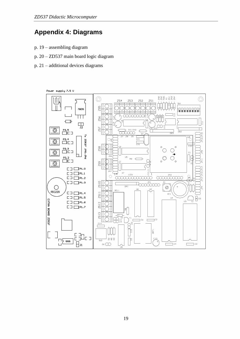
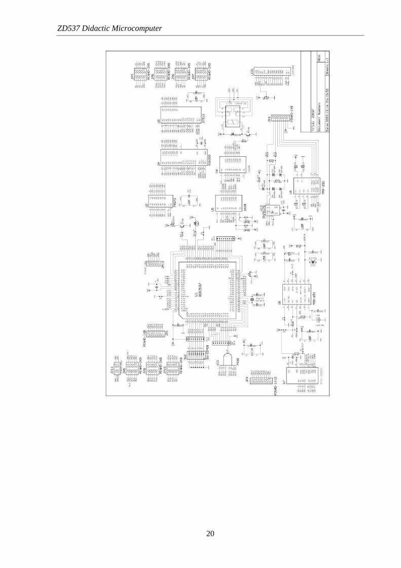
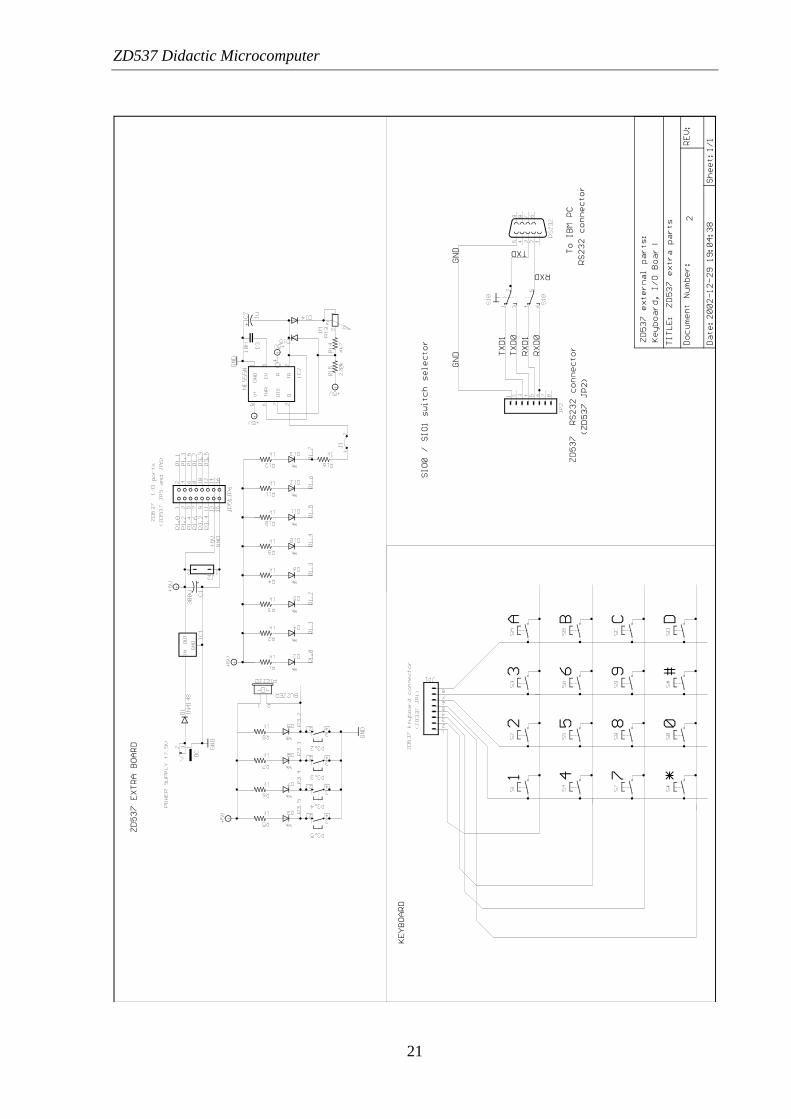
Appendix 4: Diagrams
p. 19 – assembling diagram
p. 20 – ZD537 main board logic diagram
p. 21 – additional devices diagrams
ZD537 Didactic Microcomputer
20
ZD537 Didactic Microcomputer
21

ZD537 Didactic Microcomputer
22
References
[1] Janusz Janiczek, Andrzej Stępień: Systemy Mikroprocesorowe. Mikrokontrolery.
Wydawnictwo Centrum Kształcenia Praktycznego, Wrocław 1997.
[2] Janusz Janiczek, Andrzej Stępień: Systemy Mikroprocesorowe. Mikrokontroler
80(C)51/52. Wydawnictwo Elektronicznych Zakładów Naukowych, Wrocław 1995.
[3] Andrzej Rydzewski: Mikrokomputery Jednoukładowe Rodziny MCS-51. Wydawnictwo
Naukowo – Techniczne, Warszawa 1995.
[4] Jacek Majewski, Krzysztof Kardach: Programowanie Mikrokontrolerów z Serii 8x51
w Języku C (książka z płytą CD). Oficyna Wydawnicza Politechniki Wrocławskiej,
Wrocław 2002.
[5] Piotr Gałka, Paweł Gałka: Podstawy Programowania Mikrokontrolera 8051. Warszawa
1995.
[6] Tomasz Starecki: Mikrokomputery Jednoukładowe Rodziny 51. Wyd. NOZOMI,
Warszawa 1996.
PDF files:
[7] SAB 80C517/80C537, 8-Bit CMOS Single-Chip Microcontroller: User's Manual.
Siemens Semiconductor Group, plik: 80517_USERMAN.PDF.
[8] 1M-bit CMOS Static RAM, MOS Integrated Circuit PD431000A: Data Sheet.
NEC Corp., file: RAM_431000.PDF.
[9] NMOS 512K (64K x 8) UV EPROM M27512.
SGS-THOMSON Microelectronics, file: 27512.PDF.
[10] Dot Matrix Liquid Crystal Display Controller/Driver, HD44780U.
Hitachi Ltd., file: HD44780U.PDF.
[11] Real Time Clock Module, RTC-72421/72423: Application Manual.
SEIKO EPSON Corp., file: RTC72421_APPMAN.PDF.
[12] Microprocessor Supervisory Circuits: MAX691.
Maxim Integrated Products, file: MAX691A-MAX800M.PDF.
[13] Precision, Single-Supply SPST Analog Switches: MAX323.
Maxim Integrated Products, file: MAX323-MAX325.PDF.
[14] Application Note 152: Installing and Using Keil Monitor-51.
Keil Elektronik GmbH, file: MON51.PDF.
[15] SN65176B, SN75176B: Differential Bus Transceivers.
Texas Instruments Inc., file: 75176.PDF.
[16] GAL 16V8: High Performance E2CMOS PLD Generic Array Logic™.
Lattice Semiconductor Corp., file: 16V8.PDF.
[17] 74HC/HCT573: Octal D-Type Transparent Latch; 3-State.
Philips Semiconductors, file: 74HC573.PDF.