Embed Size (px)
Citation preview
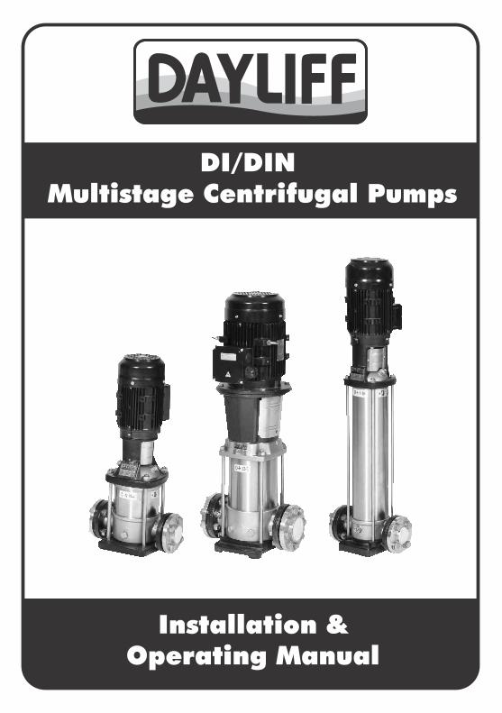
DI/DIN Multistage Centrifugal Pumps
Installation & Operating Manual

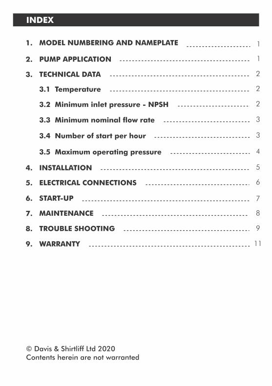
MODEL NUMBERING AND NAMEPLATE 1. 1
ELECTRICAL CONNECTIONS 5. 6
START-UP6. 7
MAINTENANCE 7. 8
INDEX
© Davis & Shirtliff Ltd 2020Contents herein are not warranted
TROUBLE SHOOTING 8. 9
WARRANTY 9. 11
PUMP APPLICATION 2. 1
INSTALLATION 4. 5
TECHNICAL DATA 3. 2
3.1 Temperature 2
3.2 Minimum inlet pressure - NPSH 2
3.3 Minimum nominal ow rate 3
3.4 Number of start per hour 3
3.5 Maximum operating pressure 4
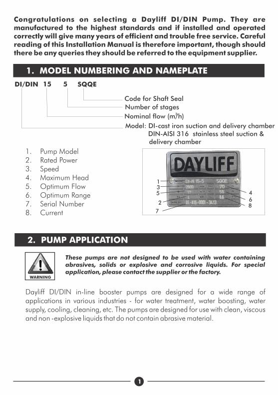
These pumps are not designed to be used with water containing abrasives, solids or explosive and corrosive liquids. For special application, please contact the supplier or the factory.
Dayliff DI/DIN in-line booster pumps are designed for a wide range of applications in various industries - for water treatment, water boosting, water supply, cooling, cleaning, etc. The pumps are designed for use with clean, viscous and non -explosive liquids that do not contain abrasive material.
1
1. MODEL NUMBERING AND NAMEPLATE
Model:
DI-cast iron suction and delivery chamberDIN-AISI 316 stainless steel suction & delivery chamber
3Nominal ow (m/h)
Number of stages
DI/DIN 15 5 SQQE
1. Pump Model2. Rated Power3. Speed4. Maximum Head5. Optimum Flow6. Optimum Range7. Serial Number8. Current
2. PUMP APPLICATION
Code for Shaft Seal
7
2
53
68
4
1
WARNING
Congratulations on selecting a Dayliff DI/DIN Pump. They are manufactured to the highest standards and if installed and operated correctly will give many years of efcient and trouble free service. Careful reading of this Installation Manual is therefore important, though should there be any queries they should be referred to the equipment supplier.
0If ambient temperatures are above +40 C, the motor’s output must be decreased to compensate for less effective cooling, and may have to be replaced with a bigger size motor.
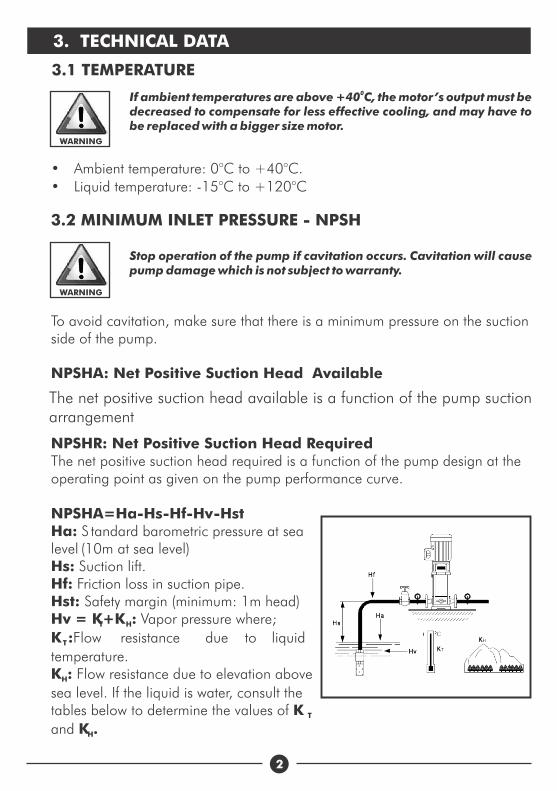
Stop operation of the pump if cavitation occurs. Cavitation will cause pump damage which is not subject to warranty.
The net positive suction head available is a function of the pump suction arrangement
2
• Ambient temperature: 0°C to +40°C. • Liquid temperature: -15°C to +120°C
WARNING
3. TECHNICAL DATA
3.1 TEMPERATURE
3.2 MINIMUM INLET PRESSURE - NPSH
WARNING
To avoid cavitation, make sure that there is a minimum pressure on the suction side of the pump. NPSHA: Net Positive Suction Head Available
NPSHR: Net Positive Suction Head RequiredThe net positive suction head required is a function of the pump design at the operating point as given on the pump performance curve.
NPSHA=Ha-Hs-Hf-Hv-Hst Ha: S
(10m at sea level) Hs: Suction lift.Hf: Friction loss in suction pipe.
Hv = K+K : Vapor pressure where;T H
K :Flow resistance due to liquid T
temperature.K : Flow resistance due to elevation above H
sea level. If the liquid is water, consult the tables below to determine the values of K Tand K .H
tandard barometric pressure at sea level
Hst: Safety margin (minimum: 1m head)
3
0T (C)
K ( )T m
H (m)
K ( )H m 0 0.55 1.1 1.65 2.2 2.75 0
20 30 40 50 60 70 80 90 100 110
0.2 0.4 0.8 1.3 2.2 3.3 5 7.4 11 15
0 500 1000 1500 2000 2500 3000
120
22
WARNING
Do not run the pump against a closed discharge valve for longer than a few seconds.
400
10
20
30
40
60 80 100 120 140
Qm
in (
%)
0t (C)
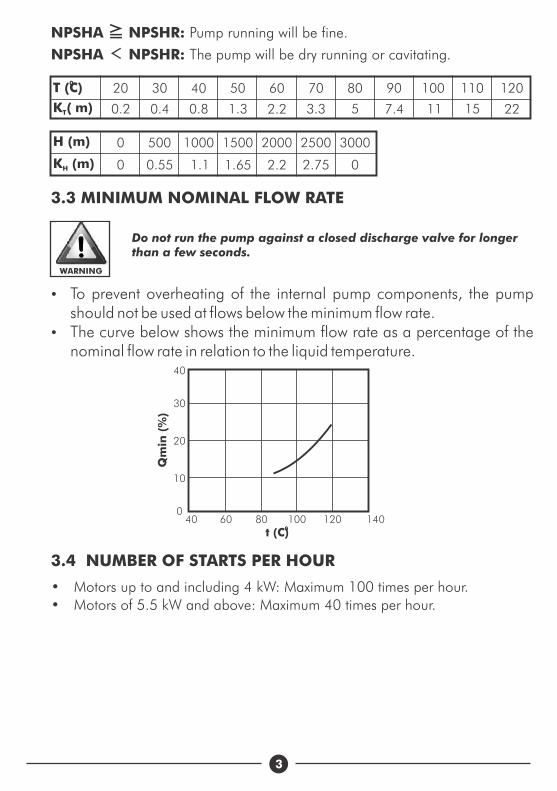
3.3 MINIMUM NOMINAL FLOW RATE
NPSHA ≧ NPSHR: Pump running will be fine.
NPSHA < NPSHR: The pump will be dry running or cavitating.
• Motors up to and including 4 kW: Maximum 100 times per hour. • Motors of 5.5 kW and above: Maximum 40 times per hour.
3.4 NUMBER OF STARTS PER HOUR
Ÿ To prevent overheating of the internal pump components, the pump should not be used at flows below the minimum flow rate.
Ÿ The curve below shows the minimum flow rate as a percentage of the nominal flow rate in relation to the liquid temperature.

4
3.5 MAXIMUM OPERATING PRESSURE
Stages StagesMaximum Operating
PressureMaximum Inlet
Pressures
DI/DIN1
DI/DIN32-36 25 bar 2-36 10 bar
2-36 25 bar2-29 10 bar31-36 15 bar
DI/DIN5
2-36 25 bar2-16 10 bar
18-36 15 barDI/DIN10
DI/DIN15
1-16 16 bar 1-6 8 bar17-22
1-10
25 bar
16 bar
7-22
1-3
10 bar
8 bar
12-17 25 bar 4-17 10 barDI/DIN20
1-10 16 bar 1-3 8 bar
12-17
8-14
25bar 4-17 10 barDI/DIN32
1-7 16 bar
30 bar
4 bar1-4
5-1011-14
10 bar15 bar
6-11
DI/DIN451-5 16 bar
30 bar
6-8
DI/DIN641-5 16 bar
30 bar
4 bar1-22-44-8
10 bar
15 bar
5-6
DI/DIN901-4 16 bar
30 bar
4 bar1-1
2-3
3-6
10 bar
15 barDI/DIN120
1-7 30 bar10 bar1-2
2-56-7
15 bar20 bar
DI/DIN150
1-6 30 bar10 bar1-1
2-45-6
15 bar
20 bar
12-13 33 bar
4 bar1-2
3-5
6-13
10 bar
15 bar
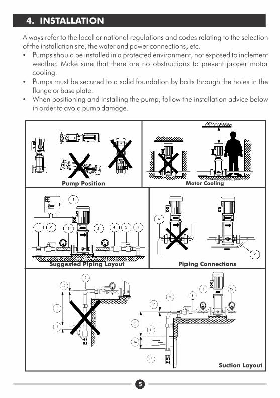
Always refer to the local or national regulations and codes relating to the selection of the installation site, the water and power connections, etc.Ÿ Pumps should be installed in a protected environment, not exposed to inclement
weather. Make sure that there are no obstructions to prevent proper motor cooling.
Ÿ Pumps must be secured to a solid foundation by bolts through the holes in the flange or base plate.
Ÿ When positioning and installing the pump, follow the installation advice below in order to avoid pump damage.
55
4. INSTALLATION
Pump Position Motor Cooling
Suggested Piping Layout Piping Connections
Suction Layout
6
Position
1
2
3
4
5
6
7
Description
Pipe support: Support piping system properly to avoid stresses on connections.
On-off valves: Install on-off valves for easy access- before the pump intake and after the pump discharge.
Use flexible piping on both input and output sides of the pump to reduce vibration and transmission of noise.
Check valves will prevent return flow of pumped liquid when pump is stopped, reducing the danger of pump damage
Control Panel: Use high quality components. Make sure that the panel conforms to local standards and regulations
Do not place elbows next to the pump intake and discharge
If pump needs to be operated in a situation that will result in cycling install a bypass line to avoid damaging the pumping system
8
9
10
11
12
13
14
15
If it is necessary to increase the diameter of the suction pipe, place an eccentric reducer between the check value and the flexible pipe section
Using elbows will increase the flow resistance. Wide bends will result in lesser flow resistance
The piping must have a level or positive gradient to prevent the formation of air pockets
Diameter of the suction pipe should be bigger than the diameter of the pumps suction port
Use a foot valve in case of negative suction head
Ensure suction lift is within limits . As a rule suction lift should be minimised
Place the intake of the suction pipe so that the intake is always submerged to prevent entry of air
Install a compound gauge at the pump suction and a pressure gauge at the pump discharge
5. ELECTRICAL CONNECTIONS
WARNING
The installer is responsible for making electrical connections to the
mains supply in compliance with relevant local regulations. Ensure
that a professional electrician carries out the electrical connections
and that the following guidelines are followed
Ÿ All electrical connection should be in accordance with the local regulations and made by a qualified electrician.
Ÿ Make sure that the supply voltage, frequency and phase supply are suitable for the motor used.
Ÿ Before proceeding, make sure that all the connections are grounded and well insulated.
Ÿ Overload protection should be provided.Ÿ To connect, proceed as shown on the inside of the terminal board cover.
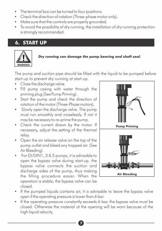
Air Bleeding
Pump Priming
7
6. START UP
The pump and suction pipe should be filled with the liquid to be pumped before start-up to prevent dry running at start-up.
WARNING
Dry running can damage the pump bearing and shaft seal.
Ÿ The terminal box can be turned to four positions.Ÿ Check the direction of rotation (Three-phase motor only).Ÿ Make sure that the controls are properly grounded.Ÿ To avoid the possibility of dry running, the installation of dry running protection
is strongly recommended.
Ÿ Close the discharge valve.Ÿ Fill pump casing with water through the
priming plug (See Pump Priming).Ÿ Start the pump and check the direction of
rotation of the motor (Three-Phase motors).Ÿ Slowly open the discharge valve. The pump
must run smoothly and noiselessly. If not it may be necessary to re-prime the pump.
Ÿ Check the current drawn by the motor. If necessary, adjust the setting of the thermal relay.
Ÿ Open the air release valve on the top of the pump outlet and bleed any trapped air. (See Air Bleeding).
Ÿ For DI/DIN1, 3 & 5 pumps, it is advisable to open the bypass valve during start-up. the bypass valve connects the suction and discharge sides of the pump, thus making the filling procedure easier. When the operation is stable, the bypass valve can be closed.
Ÿ If the pumped liquids contains air, it is advisable to leave the bypass valve open if the operating pressure is lower than 6 bar.
Ÿ If the operating pressure constantly exceeds 6 bar, the bypass valve must be closed. Otherwise the material at the opening will be worn because of the high liquid velocity.
Ÿ The pump does not have a recommended maintenance schedule. However, periodically, recommended monthly the installation should be visually checked and pump operation monitored for leaks, noise or vibration. Also the electrical installation should be inspected and the pump operating current checked, Any operational defects should be rectified accordingly.
Ÿ If the motor is fitted with grease nipples, then the motor should be lubricated with a high temperature lithium-based grease. If not, then the motor does not require regular maintenance.
Ÿ If the pump and motor are used infrequently with long intervals of non-operation, then it is recommended that the motor be greased.
8
7. MAINTENANCE
WARNING
Before starting maintenance work on the pump, the motor, or other
parts of the system, make sure that the power supply has been
switched off.
9
Pump starts but after a short time, the thermal overload trips out or the fuses blow
Check the operating conditions of the pump
The voltage is not within the motorsoperating limits
Protect the control panel from heat sources and direct sunlight
The control panel is situated in an excessively heated area or is exposedto direct sunlight
Check the power supplyA phase in the power supply is missing
8. TROUBLE SHOOTING
PROBLEM POSSIBLE CAUSE SOLUTION
Pump does notrun when the motor starter is activated
Check connections or restart the power supply
Supply failure or no power supply
Main contacts in motor starter are not making contact or the motor coils are defective
Reconnect or replace contacts or magnetic coil
Pump or auxiliary circuits protection fuses blown
Replace fuses
Pump or piping system may be obstructed
Clean the obstruction and restart pump
Motor has burst out Replace or rewind the motor
Motor protector or thermal relay hastripped out
Reset the motor or thermal protector
Tripping of dry running protection
Set the motor starter correctlyOverload setting is too low
Fasten or replace the cable connectionThe cable connection is loose or faulty
Starter overload trips mmediately pump switched on
Check the water level in the tank or thewater system pressure. If everything is inorder, check the protection device and its connection cables
Check and rectifyPump is jammed
Replace motor starter contactsContacts in overload are faulty
Replace or rewind the motorThe motor winding is defective
Check the power supplyLow voltage (especially at peak time)
The system’s general protection cuts in
Check electrical systemShort circuit
10
The pump rotates in the wrong direction when switched off
PROBLEM POSSIBLE CAUSE SOLUTION
Check and replace check valveThe foot or the check valve has failed
Repair or replace the suction pipeLeakage in the suction pipe
The pump starts up but after a period of time, the thermal overload trips
Replace motor bearingsWorn motor bearings causing motor to overheat
Partially close the on-off valve locateddischarge side until the delivery ratereturns to within the specified limits
The pumps delivery rate is higher thanthe specified rate on the pump nameplate
Disassemble and clean the pump andpiping
There are obstructions inside the pump or pumping systems
Check the actual power requirementsbased on characteristics of the liquidbeing pumped and replace the motoraccordingly
Less viscous liquids may cause the motorto work too hard and overload the motor,causing the motor to overheat
Pump runs but no water delivered
Fill the pump with the liquid to be pumped
Pump is not primed with liquid
Clean the pump, suction or dischargepipe
The pump, suction or discharge pipes are blocked by solids in the liquid being pumped
Replace the foot or check valveThe foot or check valve is blocked orhas failed
Repair or replace the suction pipeThe suction pipe leaks
Air is in the suction pipe or pump
Motor operating in wrong direction (three-phase motor)
Removed trapped air from the system
Change the direction of rotation of themotor by reversing motor connections
The pump capacity is not constant
The pump draws in air or the inlet pressure is too low
The pump or the suction side of the piping system partly blocked by foreign bodies
Improve the suction conditions
Clean the pump or suction pipe
11
9. TERMS OF WARRANTY
i) General Liability
ii) Standard Warranty
• In lieu of any warranty, condition or liability implied by law, the liability of Davis & Shirtliff (hereafter called the Company) in respect of any defect or failure of equipment supplied is limited to making good by replacement or repair (at the Company's discretion) defects which under proper use appear therein and arise solely from faulty design, materials or workmanship within a specified period. This period commences immediately after the equipment has been delivered to the customer and at its termination all liability ceases. Also the warranty period will be assessed on the basis of the date that the Company is informed of the failure.
• This warranty applies solely to equipment supplied and no claim for consequential damages, however arising, will be entertained. Also the warranty specifically excludes defects caused by fair wear and tear, the effects of careless handling, lack of maintenance, faulty installation, incompetence on the part of the equipment user, Acts of God or any other cause beyond the Company's reasonable control. Also, any repair or attempt at repair carried out by any other party invalidates all warranties.
General TermsIf equipment failure occurs in the normal course of service having been competently installed and when operating within its specified duty limits warranty will be provided as follows:-
• Up to two years - The item will be replaced or repaired at no charge.• Over two years, less than three years - The item will be replaced or
repaired at a cost to the customer of 50% of the Davis & Shirtliff market price.
The warranty on equipment supplied or installed by others is conditional upon the defective unit being promptly returned free to a Davis & Shirtliff ofce and collected thereafter when repaired. No element of site repair is included in the warranty and any site attendance costs will be payable in full at standard chargeout rates. Also proof of purchase including the purchase invoice must be provided for warranty claim to be considered.


INS330B-05/17