Embed Size (px)
Citation preview

Computer-Aided Design & Applications, Vol. 4, Nos. 1-4, 2007, pp 147-158
147
Computer Aided Manufacturability Analysis of Die-cast Parts
J. Madan1, P. V. M. Rao2 and T. K. Kundra3
1Indian Institute of Technology Delhi, New Delhi, [email protected]
2Indian Institute of Technology Delhi, New Delhi, [email protected] 3 Indian Institute of Technology Delhi, New Delhi, [email protected]
ABSTRACT
Automated manufacturability analysis is an important tool with the designer which is
meant to incorporate manufacturability aspects at initial stages of design. This paper deals with a
system developed for automated manufacturability analysis for die-cast parts. Purpose of this system
is to assist designers in their effort to come up with manufacturable die-cast parts economizing in
terms of cost and time without compromising with quality and functional requirements. Unlike most
of the work done in the past, which concentrates on manufacturability assessment of a part to be
machined, the present work deals with die-casting process. This system uses geometric reasoning to
extract manufacturing features and other information from a part CAD model. It uses a knowledge
base consisting of die-casting process knowledge and rules, to present a manufacturability advice to
the designer. Use of the proposed system is demonstrated for the manufacturability assessment of
typical die-cast parts.
Keywords: Design for manufacturability (DFM), Geometric reasoning, Die-casting, Process
knowledge, Feature recognition.
1. INTRODUCTION
Die-casting is a ‘near net shape’ manufacturing process extensively used for realizing quality products required in many
engineering applications. Advantages of die-casting process are higher production rate, lower cost, better quality and
process automation. It uses a permanent mould made of metal which can be used repeatedly. Die-casting process
primarily uses two mould halves known as core and cavity which are assembled and poured with molten metal under
high pressure. After solidification, these mould halves are separated and solid part is ejected with the help of an ejector
mechanism. Figure 1 shows die-casting process schematically along with terminology. A part to be made with die-
casting should be designed keeping in view many process considerations. In other words a part goes through
modifications to make it compatible with the process. This is done by involving manufacturing persons to make critical
suggestions on part design and is known as manufacturability analysis. Normally more than one such iteration between
design and manufacturing teams is required to finalize design.
Fig. 1: Die-casting process terminology.
Cavity half
Core half
Part
Side-core
Parting direction
Undercut

Computer-Aided Design & Applications, Vol. 4, Nos. 1-4, 2007, pp 147-158
148
Industries today are striving to achieve lower product development time, higher productivity and efficiency. In
large enterprises where design and manufacturing personnel may be stationed at different locations has given rise to
concept of Design for Manufacture (DFM). In words of Van Vliet et al. [30], ‘DFM or Design for Manufacturing implies
optimization of the product and process concepts during the design phase of a product to ensure ease of manufacture’.
It has been reported that 70% of the cost of a part is decided at the design stage itself [1]. Introducing DFM would have
implied benefits. Importance of DFM has been highlighted by many authors [9, 11, 14, 17, 23, 27, 28, 30].
Incorporating DFM tools is very important for smooth transition from design to manufacture. A designer must be
provided with up-to-date knowledge of manufacturing process and tools or must be given DFM support. Implementing
DFM will have the benefits of improved manufacturability of product design, shorter time-to-market and reduced cost.
Three areas where DFM can be applied are: Verification; Quantification and Optimization [30]. Gupta et al [11] have
classified DFM into direct or rule based approaches. In rule based approach, rules are used to identify design attributes
which are beyond process capabilities, while in plan based approach the first step is to generate feasible process plan
and to find most suitable plan in order to reduce time or cost. Shah and Wright [27] have identified DFM metrics which
include qualitative (good practice rules etc.) and quantitative (cost and time estimates etc.) methods.
Most of the work in DFM has been done in the machining [11, 32] or sheet metal working [25, 31] domain,
while little attention has been given to die casting. Moreover comprehensive automated manufacturability studies of
die-cast parts are almost non-existent. In die-casting, implementation of DFM is important as production lead times are
particularly longer. This is due to more number of iterations required between design and manufacturing teams; die
design and manufacturing, and process simulation and testing required before production is started. Some work in
reducing production lead times has been done in the area of mold design [33, 34]. This study attempts to address the
issue of automated DFM analysis for die-cast parts and is along the lines of earlier work reported from our laboratory
[25]. This paper is organized in the following sections. Section 2 gives previous work and objectives of present study.
Die-casting process constraints and design guidelines are discussed in section 3. Section 4 details methodology to
extract part attributes and features from part CAD model. Section 5 presents computer aided design for
manufacturability analysis system architecture. Lastly implementation and results, and conclusions are discussed in
section 6 and 7 respectively.
2. PREVIOUS RESEARCH AND OBJECTIVES OF PRESENT STUDY
Manufacturing aspects to be considered in design of a die casting part is well documented [2, 3, 8, 22]. Research has
been done in die-casting to automate activities like cost estimation, process simulation and finding part design-process
compatibility using interactive systems. We discuss here some papers which fall in the category of manufacturability
analysis of die-casting. Some relevant papers on injection moulding are also included because of similarities of
injection moulding and die-casting process.
Hanada and Leifer [13] presented a knowledge based system which identifies features in an interactive
session with the user. Features like slab, boss and rib were recognized and information gathered was used to modify
part shape. Although it used rules for part modification but issues like checking part suitability for process etc. were not
given. Lenau et al [19] investigated manufacturing issues to be taken at design stage for a die-casting part. They
focused on level of detailing and accessibility of part information required passing from design to production. Ishii and
Miller [16] used Pro/E CAD modeler with Nexpert a knowledge based system which contained process specific
knowledge. It determines part envelope size, height, nominal wall thickness and compares it with recommended
values. It dealt with a few part attributes only and manufacturability issues at part feature level were not addressed.
Venketchalam et al [29] developed an interactive knowledge based system which prompted the user to enter properties
of die-cast part and tolerances etc. This was in addition to process selection and part cost estimation. It recognizes
overall part attributes only and gives advice to adjust these attributes according to process limitations. Grosse and Sahu
[12] presented a methodology for preliminary design of injection moulded load carrying 3D component based on
functional and manufacturing considerations. It compared design alternatives with an evaluation criterion given by the
user.
Chen et al [4] presented a systemic approach to develop an automated manufacturability assessment. It used
knowledge base of design rules which were material specific. Width, thickness and depth were used for
manufacturability assessment, which were extracted from part database. It used specific feature shapes only which
seem to be inadequate for die-casting. Chen [5] developed a computer aided system which used principles of
concurrent engineering by using a collaborative environment. Locket and Marin [17] developed an intelligent
manufacturing advisor for die-casting and injection moulding which used mid-surface of the part CAD model to
recognize features. It depended on quality of the mid surface generated from CAD system and because of this
limitation it sometimes gives inconsistent results. Also, it could not produce good results in case of varying wall

Computer-Aided Design & Applications, Vol. 4, Nos. 1-4, 2007, pp 147-158
149
thickness, very small features and complex features and was limited to feature recognition only. Chen et al [6]
presented a method to extract geometric characteristics for manufacturing assessment of net shape processes. It made
use of features in feature-based design and thus depended on design history chosen by the designer. It’s evaluation
knowledge and rules were limited. Zhao and Shah [31] presented a domain independent shell for DFM, which
included injection moulded parts. It covered both technical and economical feasibility for manufacturability assessment.
They used global manufacturing aspects (material, size etc.) to choose suitable process. Process specific aspects (major
feature, shape, size etc.) and machine specific aspects (tolerance, surface finish etc.) were also used to evaluate
manufacturability. Part attributes were taken from ACIS modeler. However it was not capable of recognizing
manufacturing features and was partly automated. Besides this it did not evaluate geometric aspects for
manufacturability. Deng et al [7] gave a shape modification system which was based on FEM analysis of a part. It
iterates by changing part design parameters, to evaluate and compare part designs to find most suitable design. But
manufacturability advice for design improvement was missing in their work.
An overview of above discussed literatures shows that there are several limitations in previous reported work.
Some of these systems take part information interactively, while others take only overall part attributes from the CAD
model. DFM issues like identifying part features which are inaccessible to the molding tool, areas with wall thickness
variations, features which violate process limitations and certain suggestions to the designer which can improve the part
design and are based on good practice rules remain largely unaddressed. In the present study an attempt has been
made to generate an automated manufacturability advice from part CAD model which can be used as a feedback by
the designer to improve design. Further automated cost and time estimation were also incorporated so that designer
can know the effect of design changes on cost and time estimation. In this way this system is more comprehensive as it
addresses two phases of manufacturability analysis i.e., design verification and quantification. Detailed methodology of
the system is discussed in following sections.
3. PROCESS CONSTRAINTS AND DESIGN GUIDELINES
A part to be die-cast should possess certain design characteristics to make it suitable for manufacturing with die-casting
process. For example there is limitation on maximum weight of the part beyond which the part is not manufacturable.
Similarly there are other aspects related to part geometry which should be in conformance with process capabilities.
Following sub-sections elaborate these constraints and guidelines.
3.1 Part Geometry Limitations
Die-casting molding tool namely core, cavity and side cores are made of solid metal which have to be disengaged after
solidification of molten metal. This is different from normal casting process where cavity and the core are made of
sand, are collapsible and can be broken for getting the solid part. Because of this fact there are some geometric aspects
which need to be considered while designing the part. Hui [15] has discussed some of the geometric aspects related to
mouldablility of a part. Some features which cause accessibility problems are not allowed in die-casting. These are
explained in the following paragraph with the help of figure 2 (a-f).
- Internal undercuts like depressions or protrusions need internal side-cores and are not allowed in die-casting.
- Partially visible depression features like holes with smaller opening diameter and larger diameter at the base.
- Features with reverse draft and void features.
3.2 Overall Part Attributes
Die casting process have limitations on overall part characteristics like part weight, surface area, wall thickness,
material, size, tolerance and surface finish. If any of the attributes is exceeding the process limits, it may not be feasible
to successfully complete the process. Further these limitations are dependent on type of material which makes it
necessary for the designer to evaluate part against material specific process constraints. These part attributes are
evaluated with the help of a knowledge base which represents material specific process constraints. Table 1 shows
representative database of material specific process capabilities.

Computer-Aided Design & Applications, Vol. 4, Nos. 1-4, 2007, pp 147-158
150
Rounded
Internal undercuts
Partially visible depressions
Reverse draft Void
Fig. 2: Part geometrical limitations.
Attribute
Material
Zn Al Mg Cu
Weight (Kg) 30 45 16 07
Effective projective area (m2) 0.77 0.77 0.77 0.77
Recommended minimum wall thickness (mm)
<25
25-100
100-500
500-2000 Surface
area (cm
2)
2000- 5000
0.38-0.75
0.75-1.3
1.3-1.8
1.8-2.2
2.2-4.6
0.75-1.3
1.3-1.8
1.8-2.2
2.2-2.8
2.8-6.0
0.75-1.3
1.3-1.8
1.8-2.2
2.2-2.8
2.8-6.0
1.5-2.0
2.0-2.5
2.5-3.0
------
------
Maximum wall thickness 6 6 6 6
Tab. 1: Die-casting material and process constraints (Source: [3, 22]).
Undesirable Desirable
Sharp edge
Rounded
edge Sharp edges are to be blended with round of radius 1.5 times nominal wall thickness.
Sharp circular edges to be blended with 0.01-0.015 times radius concave round to facilitate assembly
Sharp corners
(b) (d)
(a) (c) (e)
(f)
Computer-Aided Design & Applications, Vol. 4, Nos. 1-4, 2007, pp 147-158
151
Thick sections Thin sections
Thick sections should be replaced with thin sections
Large flat surfaces should be reinforced with ribs
Deep cavities in opposite directions
Deep cavities in same direction
Deep cavities should be on core half side if possible
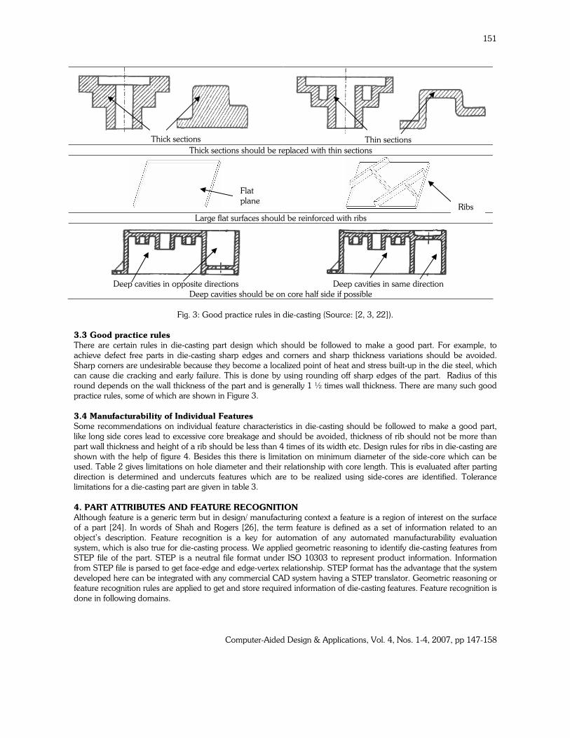
Fig. 3: Good practice rules in die-casting (Source: [2, 3, 22]).
3.3 Good practice rules
There are certain rules in die-casting part design which should be followed to make a good part. For example, to
achieve defect free parts in die-casting sharp edges and corners and sharp thickness variations should be avoided.
Sharp corners are undesirable because they become a localized point of heat and stress built-up in the die steel, which
can cause die cracking and early failure. This is done by using rounding off sharp edges of the part. Radius of this
round depends on the wall thickness of the part and is generally 1 ½ times wall thickness. There are many such good
practice rules, some of which are shown in Figure 3.
3.4 Manufacturability of Individual Features
Some recommendations on individual feature characteristics in die-casting should be followed to make a good part,
like long side cores lead to excessive core breakage and should be avoided, thickness of rib should not be more than
part wall thickness and height of a rib should be less than 4 times of its width etc. Design rules for ribs in die-casting are
shown with the help of figure 4. Besides this there is limitation on minimum diameter of the side-core which can be
used. Table 2 gives limitations on hole diameter and their relationship with core length. This is evaluated after parting
direction is determined and undercuts features which are to be realized using side-cores are identified. Tolerance
limitations for a die-casting part are given in table 3.
4. PART ATTRIBUTES AND FEATURE RECOGNITION
Although feature is a generic term but in design/ manufacturing context a feature is a region of interest on the surface
of a part [24]. In words of Shah and Rogers [26], the term feature is defined as a set of information related to an
object’s description. Feature recognition is a key for automation of any automated manufacturability evaluation
system, which is also true for die-casting process. We applied geometric reasoning to identify die-casting features from
STEP file of the part. STEP is a neutral file format under ISO 10303 to represent product information. Information
from STEP file is parsed to get face-edge and edge-vertex relationship. STEP format has the advantage that the system
developed here can be integrated with any commercial CAD system having a STEP translator. Geometric reasoning or
feature recognition rules are applied to get and store required information of die-casting features. Feature recognition is
done in following domains.
Flat
plane Ribs

Computer-Aided Design & Applications, Vol. 4, Nos. 1-4, 2007, pp 147-158
152
Non-manufacturability features: Any features or regions of the part which pose moulding tool disengagement
problems are identified so that same can be reported to the designer.
Alloy Hole Diameter (mm) 3 4 6 19 25
Maximum depth (mm)
Zinc 10 14 25 115 150
Aluminium 8 13 25 115 150
Magnesium 8 25 25 115 150
Copper ------- ------- 50 90 125
Tab. 2: Side-core diameter and maximum length limitations (Source: [3])
Alloy Zinc Aluminium Magnesium Copper
For critical dimensions
Upto 25 mm ± 0.08 ±0.10 ±0.10 ±0.18
Each additional 25mm over 25-300mm ±0.025 ±0.038 ±0.038 ±0.05
Each additional 25mm over 300mm 0.025 ±0.025 ±0.025
For non-critical dimensions
Upto 25 mm ±0.25 ±0.25 ±0.25 ±0.35
Each additional 25mm over 25-300mm ±0.038 ±0.05 ±0.05 ±0.08
Each additional 25mm over 300mm ±0.025 ±0.025 ±0.025 -----
Tab. 3: Recommended tolerances for die-casting part (Source: [3])
Features requiring side-cores: This requires identifying die-casting features. Die-casting features are nothing but
depression or protrusion features of the part. All such features are identified and parting direction and parting line are
generated. Determination of parting direction is important to identify those die-casting features which require a side-
core for molding. Die-casting features which can not be molded with core and cavity half and need a separate side-
core are also identified. Authors have developed a system [20] which gives different die-casting features in detail and
their method of recognition and is used in this system. Methodology to automatically determine parting direction and
parting line is also discussed in our earlier system [20].
Part attributes: Overall attributes of the part like volume, surface area are directly extracted from the part CAD
model, while tolerance and surface finish evaluation is performed interactively because of non availability of this data
in machine readable format. Nominal wall thickness was calculated by taking ratio of volume to the surface area.
Fig. 4: Design rules related with rib feature.
Wall thickness: It is important to identify regions of the part which violate thickness constraints like minimum and
maximum allowed wall thickness and even sharp thickness variations. It is very critical in die-casting process to obtain
Rib height should not
be more than 4 times
width
Ribs
Distance between two
ribs should be less
than 4 times thickness
Rib thickness
should be
equal to wall
thickness

Computer-Aided Design & Applications, Vol. 4, Nos. 1-4, 2007, pp 147-158
153
parts with uniform wall thickness and smooth variations. Use of proprietary software GeomCaliper® [10] was made to
analyze any thickness violations.
Sharp edges: Automated identification of such edges is done by extracting this information from part B-rep data. In
geometric terms if two planar surfaces are meeting at an edge which is linear, they should be blended with a cylindrical
surface. For example ‘if two adjacent faces are planar connected by a linear edge, then a sharp edge is present’.
Similarly smooth edges with insufficient round radius are also identified.
Rib features: These are those protrusion features in die casting which are having wall thickness comparable to the
nominal wall thickness and much larger length. These are also identified by geometric reasoning from part B-rep data.
For example for the rib feature shown in figure 4, surface 1 is having two convex edges and all other subsequent
connected edges are concave indicating presence of a rib feature.
5. MANUFACTURABILITY EVALUATION SYSTEM
This section gives salient features and overall architecture of the computer aided manufacturability evaluation system
for die-cast parts. This system checks a given design of die-cast part for manufacturability. It gives advice in terms of
possible design changes in order to overcome design and process planning violations to facilitate ease of
manufacturing. The architecture of the automated manufacturability evaluation system developed is shown in figure 5.
Integrated elements of the system are part model, geometric reasoner, design evaluator, process knowledge, feature
data and knowledge, material and energy data, manufacturing resource data, tooling knowledge and feature mapping
knowledge.
Proposed system takes CAD model of the part as input. Part attributes and manufacturing features are
recognized using feature recognition module which recognizes required information from part B-rep data obtained
from STEP file using geometric reasoning knowledge. It maintains a knowledge base of process related considerations,
which is in terms of material sensitive die-casting process limitations and capabilities. Material and energy database
provides information related to properties and prevalent cost. As parting direction and parting line are crucial for
manufacturability assessment of die-cast parts, same was also obtained automatically using parting direction and line
module. This is important to identify those features which need a side-core in the molding process. Earlier, authors
have developed a system for automated determination of manufacturing cost of die-cast parts using part CAD model
[20], wherein detailed methodology of die-casting feature recognition, parting direction and parting line determination
has been discussed. We used the same methodology which also helped in identifying features requiring side-cores.
Feature recognition in this system in addition includes features discussed in section 4. Tolerances are addressed
separately by user interface at this stage because of unavailability of tolerance information in machine readable format.
As thickness analysis is very crucial for die-cast parts, GeomCaliper® [10] was used for this purpose by opting rolling
spherical ball algorithm provided in this software and was quite useful. Time and cost estimation module in addition
uses feature mapping knowledge, manufacturing resources and tooling data and knowledge to arrive at time and cost
estimates. Details of time and cost estimation can be found in our earlier work [21]. System was found to be helpful in
reducing the number of iterations between design and manufacturing, which reduced development time of the part
significantly. In this way productivity and efficiency of the designer was improved significantly to achieve objectives of
manufacturable parts which are economical also. System architecture is shown in figure 5.
6. IMPLEMENTATION AND RESULTS
Proposed system has been implemented using MATLAB 7 on Windows 2000 platform. A designer after preparing part
design in CAD modeler requests for manufacturing advice by submitting part CAD model to the system. This design is
evaluated for identifying non-manufacturable design features and a feedback is given to the designer. Designer
incorporates changes suggested by redesigning the part. Time and cost estimation of original design and the
redesigned part are displayed to quantify any manufacturability improvement. Results of computer aided
manufacturability analysis for two typical die-casting parts shown in figures 6(a) and 7(a) are presented here.
Manufacturability advice generated for example part 1 and example part 2 shown in figure 6 (a) and 7(a) are given in
table 4 and table 5 respectively. Manufacturability advice for individual features of this part is correlated by indicating
serial number of the advice in the figure. Part designs after manufacturability advice was incorporated in initial design
of these examples are shown in figures 6(b) and 7(b) respectively. When this manufacturability advice was
implemented, there was significant improvement in manufacturability as indicated by manufacturing time and cost
figures shown alongside respective part figures. This is in addition to reduced number of design iterations which lead to
reduction in development time and cost.

Computer-Aided Design & Applications, Vol. 4, Nos. 1-4, 2007, pp 147-158
154
Fig. 5: Automated manufacturability analysis system architecture.
S. No. Part attribute/ feature Manufacturability evaluation and advise
1. Weight : 1090 gm Is within process limits.
2. Projected area: 154 cm2 Is within process limits.
3. Average thickness : 4.4mm Thickness of the part is very high and need to be reduced.
4. Minimum wall thickness: 0.34 mm Is violated at many places and should be rectified.
5. Maximum wall thickness: 20 mm Maximum wall thickness should be reduced to below 6.3 mm.
6. Solid boss of ¢20mm. Solid boss of 10mm can be made thinner by making it hollow or
removing material from the back.
7. Solid boss of ¢20mm. Is having sharp corner with the planar face and it’s edges should be
rounded. A concave round (by material removal)can be used if this
edge is to be used for assembly.
8. Sharp edges There are sharp edges which should be rounded off.
9. Side hole of ¢20mm. Edges of this hole should be rounded off or chamfered if they are to
be used for tapping.
10. Hollow cylindrical feature with 5mm
wall thickness
Wall thickness of 5mm can be reduced. Ribs can be used to
increase its strength.
11. Large planar surface There is a large planar surface of area 152mm2 which can be
reinforced with ribs to reduce thickness and increase strength.
12. Side hole of ¢4mm Its length of 30mm which is larger than process limits. Either this
length should be decreased or diameter should be increased. A
chamfer can be used at its opening, if used for assembly.
13. Internal undercut of ¢10mm Is not allowed and should be removed or made a through hole.
Geometric
reasoning &
knowledge
Material
&
Energy data
Process
capabilities
&
constraints
No
Manufacturing resources
Tooling data and
knowledge
Part CAD model USER
Geometric
evaluation
Thickness analyzer
Parting direction
and line Feature
recognition
Overall part
attributes
Is design
acceptable?
Feature mapping
Manufactur-
ability advice
Time and cost
estimation
Yes

Computer-Aided Design & Applications, Vol. 4, Nos. 1-4, 2007, pp 147-158
155
Fig. 6 (a) Example part 1 Fig. 6(b) Redesigned example part 1
Fig. 7 (a): Example part 2 Fig. 7(b): Redesigned example part 2
S. No. Part attribute/ feature Manufacturability evaluation and advise
14. Weight : 1090 gm Is within process limits.
15. Projected area: 154 cm2 Is within process limits.
16. Average thickness : 4.4mm Thickness of the part is very high and need to be reduced.
17. Minimum wall thickness: 0.34 mm Is violated at many places and should be rectified.
18. Maximum wall thickness: 20 mm Maximum wall thickness should be reduced to below 6.3 mm.
19. Solid boss of ¢20mm. Solid boss of 10mm can be made thinner by making it hollow or
removing material from the back.
20. Solid boss of ¢20mm. Is having sharp corner with the planar face and it’s edges should be
rounded. A concave round (by material removal)can be used if this
edge is to be used for assembly.
21. Sharp edges There are sharp edges which should be rounded off.
22. Side hole of ¢20mm. Edges of this hole should be rounded off or chamfered if they are to
be used for tapping.
23. Hollow cylindrical feature with 5mm
wall thickness
Wall thickness of 5mm can be reduced. Ribs can be used to
increase its strength.
24. Large planar surface There is a large planar surface of area 152mm2 which can be
reinforced with ribs to reduce thickness and increase strength.
25. Side hole of ¢4mm Its length of 30mm which is larger than process limits. Either this
length should be decreased or diameter should be increased. A
chamfer can be used at its opening, if used for assembly.
Example part 1
Cost ($) Time (s)
Before redesign
30.0 137
After redesign
18.9 85
8
7
6
10
11
13
9 12
7, 8
11
12, 13
16
14, 15
18
17 9, 10
Example part 2
Cost ($) Time (s)
Before redesign
128.0 138
After redesign
61.0 80

Computer-Aided Design & Applications, Vol. 4, Nos. 1-4, 2007, pp 147-158
156
26. Internal undercut of ¢10mm Is not allowed and should be removed or made a through hole.
Tab. 4: Part manufacturability evaluation and advice.
S. No. Part attribute/ feature Manufacturability evaluation and advise
1. Weight : 4120 gm Is within limits of process.
2. Projected area: 549 cm2 Is within process limits.
3. Average thickness : 9.4 mm Is higher than process capabilities and need to be reduced.
4. Minimum wall thickness: 2.6mm Is within the limits.
5. Maximum wall thickness: 30mm Maximum wall thickness should be reduced below 6.3 mm.
6. Number of side-cores. = 3 Number of side-cores required is high and should be reduced.
7. Side hole of ¢5mm Is having length of 30mm and is not in process limits. Its
diameter should be increased or length be reduced.
8. Side hole of ¢5mm This hole should be chamfered at its opening and should be
rounded off at bottom.
9. Rib width = 5mm Thickness of the rib is high and should be made equal to wall
thickness.
10. Rib height = 50mm Rib height is more and should be reduced to below 4 times
thickness.
11. Sharp edges of ribs Sharp edges at bottom and top and should be rounded.
12. Side holes (#4) ¢16mm length 40mm Are within the process limits.
13. Side holes (#4) ¢16mm length 40mm Are having sharp edges at opening and bottom and should be
provided with chamfers or rounds.
14. Step side hole ¢40mm length 120mm Is within process limits.
15. Step side hole ¢40mm length 120mm Is having sharp edges at opening and bottom and should be
provided with chamfers or rounds.
16. Annular cylindrical protrusion Is having sharp edges at the bottom and should be rounded.
17. Large planar surface There is a large planar surface of area 540mm2 which can be
reinforced with ribs or recesses at intervals.
18. Sharp edges There are many sharp edges in the part and should be rounded
or smoothened.
19. Non-moldable areas There are no regions posing tool disengagement problems.
Tab. 5: Part manufacturability evaluation and advice for example part 2.
7. CONCLUSIONS
A system for computer aided design for manufacturability analysis of die-cast parts is presented. Developed system is
more comprehensive than the earlier proposed ones in the sense that it unites the features of both rule-based and plan-
based methods of design evaluation. It is expected that such a system will be extremely useful for a designer with
functional knowledge to get quick feedback about improving manufacturing productivity without any detailed
knowledge about the process. Sometimes, manufacturability feedback suggestions are not accepted by the designer
when they violate the functional requirements. The method can be used to evaluate manufacturability at the
completion of part design or incrementally during design process. In the present work, functional requirements of a part
were not accounted for. It was left to the designer to accept or reject a manufacturability evaluation suggestion keeping
in mind the functional requirements.
As implementation of manufacturability advice is left to the designer, further work can be done to achieve
automation to generate the redesigned part. Lastly considering interacting features and those with free form surfaces
would further improve this system and make it quite useful for industry.
8. REFERENCES
[1] Barton, J. A; Love, D. M; Taylor, G. D.: Design determines 70% of cost: A review of implications for design
evaluation, J. Engineering Manufacture, 12 (1), 2001, 41-58.
[2] Boothroyd, G.; Dewhurst; P.; Knight, W.: Product Design for Manufacture and Assembly, Marcel Dekker Inc.,
New York, 1994.
Computer-Aided Design & Applications, Vol. 4, Nos. 1-4, 2007, pp 147-158
157
[3] Bralla, J.G.: Design for Manufacturability Handbook, McGraw Hill, New York, 1999.
[4] Chen, Y.-M.; Miller, R. A; Sevellar, K.: Knowledge-based manufacturability assessment: an object-oriented
approach, Journal of Intelligent Manufacturing, 6, 1995, 321-337
[5] Chen, Y.-M.: Development of a computer-aided concurrent net shape product and process development
environment, Robotics and Computer Integrated Manufacturing, 13 (4), 1997, 337-360.
[6] Chen, Y. –M.; Wen, C. C.; Ho, C. T.: Extraction of geometric characteristics for manufacturability assessment,
Robotics and Computer Integrated Manufacturing, 19, 2003, 371–385.
[7] Deng, Y. M.; Britton, G. A; Lam, Y. C: Towards automatic shape modification in injection-moulded-plastic-part
design, 2005. (Available online: DOI 10.1007/s00170-004-2388-9)
[8] Dixon, J. R.; Poli, C.: Engineering Design and Design for Manufacture, Field Stone Publishers, Massachusetts,
USA, 1995.
[9] Driscoll, M. O.: Design for manufacture, Journal of Materials Processing Technology, 22, 2002, 318–321.
[10] GeomCaliper® Software, Geometric Software Solutions Limited, USA.
[11] Gupta, S. K.;, Das, D.; Regli, W. C; Nau, D. S.: Automated manufacturability analysis: A survey, Research in
Engineering Design, 9(3), 1997, 168-190.
[12] Grosse, I. R.; Sahu, K.: Preliminary design of injection moulded parts based on manufacturing and functional
simulations. In Advances in Feature Based Manufacturing. (Shah, J. J.; Mantyla M.; Nau, D. S.: Elsevier
Science Limited, 1994.)
[13] Hanada, H.; Leifer, L. J.: Intelligent design system for injection moulded parts based on the process function
analysis method, Proc. NSF Engineering Design Research Conf., Amherts, MA, 1989, 599–612.
[14] Herrmann, J. A; Cooper, J.; Gupta, S. K; Hayes, C. C.; Ishii, K.; Kazmer, D.; Sandborn, P. A.; Wood, W. A.:
New Directions In Design For Manufacturing, Proceedings of ASME, DETC 2004-57770, September 28-
October 2, 2004, Salt Lake City, Utah USA.
[15] Hui, K. C.: Geometric aspects of the mouldability of parts, Computer aided design, 29 (3), 1997, 197-208.
[16] Ishii, K.; Miller, R. A.; Design Representation for Manufacturability Evaluation in CAD: Beyond Feature-based
Design, ASME/ CIE ’92 AI stream, 1992.
[17] Kuo, T. C.; Huang, S. M.; Zhang, H. C.: Design for manufacture and design for‚ X’: Concepts, applications and
perspectives, Computers & Industrial Engineering, 41, 2001, 241-260.
[18] Lockett, H. L.; Guenov, M. D.: An Intelligent Manufacturing Advisor for Casting and Injection-Moulding Based
On A Mid-Surface Approach, Proceedings of ASME, DETC2002/CIE-34497, Montreal, Canada, September 29-
October 2, 2002.
[19] Lenau, T.; Nielsen, L.H.; Alting, L.: Design for Pressure Die Casting--a DFM Example, International Journal of
Advanced Manufacturing Technology, Vol. 6 (2), 1991, 141-154.
[20] Madan, J.; P. V. M. Rao; Kundra, T. K.: An automated cost estimation system for die-cast parts, Transactions of
ASME Journal of Computing and Information Science in Engineering, 2006. (Article submitted)
[21] Madan, J.; P. V. M Rao.; Kundra, T. K.: System for early cost estimation of die-cast parts, International Journal
of Production Research, 2006. (Available online)
[22] Product Design for Die Casting, North American Die Casting Association (NADCA), Rosemont, USA, 1998.
[23] Poli, C.; Dastidar, P.; Fernandez, R.: Design Knowledge Acquisition for DFM Methodologies, Research in
Engineering Design, 4, 1992, 131-145.
[24] Pratt, M. J.; Wilson, P. R.: Requirements for support of form features in a solid modeling system', CAM-I, R-85-
ASPP-01, 1985.
[25] Ramana, K. V.; Rao, P. V. M.: Automated manufacturability evaluation system for sheet metal components in
mass production, International Journal of Production Research, 43 (18), 2005, 3889–3913.
[26] Shah, J.; Rogers, M.: Functional Requirements and Conceptual Design of Feature Based Modeling System,
Journal of Computer Aided Engineering, 5(1), 1988, 9-15.
[27] Shah, J. J.; Wright, P. K.: Developing theoretical foundations of DfM, DETC2000/ DFM 14015, September 10-
14, Baltimore, MD, 2000.
[28] Stauffer, L.; Rule, R.: A template for design for manufacture guidelines, Proceedings of ASME,
DETC2003/DFM-48135, Chicago, Illinois, USA, September 2-6, 2003.
[29] Venkatchalam, A. R.; Mellichamp, J. A.; Miller, D. M.: A knowledge-based approach to design for
manufacturability, Journal of Intelligent Manufacturing, 4, 1993, 355-366.
[30] Van Vliet, J. W.; Van Luttervelt, C. A.; Kals, H. J. J.: State of the art report on design for manufacturing,
Proceedings of ASME DETC, Las Vegas, Navada, September 12-15, 1999.

Computer-Aided Design & Applications, Vol. 4, Nos. 1-4, 2007, pp 147-158
158
[31] Zhao, Z.; Shah, J. J.: Domain independent shell for DfM and its application to sheet metal forming and injection
molding, Computer-Aided Design, 37, 2005, 881–898.
[32] Srikumaran, S.; Sivaloganathan, S.: Proving manufacturability at the design stage using commercial modeling
software, Computer-Aided Design and Applications, 2 (1-4), 2005, 507-516.
[33] Song, I. –H.; Park, J. –M; Chung, S. –C: web based interference verification system for injection mold design,
Computer-Aided Design and Applications, 3 (1-4), 2005, 129-138.
[34] Ni, Q.; Lu, W. F.; Yarlagadda, P. K. D. V.: A PDM-based framework for Design to Manufacturing in mold
making industry, 3 (1-4), 211-220.