Embed Size (px)
Citation preview
“Manufacturer of Die Sets and Components”
DIE SETENGINEERING
HANDBOOKand
CATALOG
COMPLETE WITH METRIC DIMENSIONS
SERVICING INDUSTRY SINCE 1918
CORPORATE HEADQUARTERS
6779 Engle Road Suite A-F • Cleveland, Ohio 44130-7926(216) 898-6270 • Toll Free: (800) 321-8632 • Fax: (800) 221-6310
INTERNATIONAL DIVISION
Cleveland, Ohio(216) 898-6270
Fax: (216) 898-6247
SAVE TIME GET ONLINE
To find out more on what Lempco can do for you, please visit our web site atwww.lempco.com
Also see page 41 for our C.A.D. E-Mail Instructions
Printed in the United States of AmericaCopyright © 2004 by Lempco, A Division of Connell Limited Partnership
All rights reserved. No reproduction of thecontents of this book, in whole or in part,
may be made in any form.
★ ★ ★ ★ ★ Assurance Policy ★★★★★Lempco’s Ball Bearing Die Set equipped
with the patented rotainer oftenoutlasts the life of the die.
It’s this reliability and assurance thatproduction specialists buy from the
“innovator” of the ball bearing die set.Uninterrupted high press production is a tradition with Lempco. A Lempco Ball BearingRotainer® Equipped Die Set has guide posts and bushings made from 52100 toolsteel, through hardened to withstand the dependable Lempco preload. Careful testshave yielded many case histories showing that even after 25 million or more strokes apreload still exists. The life you may expect depends upon your application and othervariable circumstances.
THIS IS PRODUCTION!The amount of downtime chargeable to regrinding, die set maintenance and repairsmust also be held to a minimum. Lempco’s Rotainer® Equipped Ball Bearing Die Setoffers this opportunity under a heading of “accuracy.” Because a Lempco Rotainer®
Equipped Ball Bearing Die Set is so accurate there is less die wear, less scrap, lesschance of seizure. Cost records show that 30% to 50% of the die maker’s time isconsumed at the bench - fitting, mounting, aligning.The accuracy of a LempcoRotainer® Equipped Ball Bearing Die Set reduces this expense.
THESE ARE PROFIT FACTORS!The time-tested Lempco Ball Bearing Rotainer ®Equipped Die Set means RELIABILITY,PRODUCTION, ACCURACY AND PROFIT! Check the results. TRY A LEMPCO BALLBEARING ROTAINER® EQUIPPED DIE SET AND INCREASE YOUR PRODUCTIVITYAND PROFIT.
For more information contact the Lempco distributor in your area or call TOLL FREE800-321-8632.
The Dependable Die Set Company
QUALITY • DEPENDABILITY • SERVICE • SINCE 1918
To the Metalworking Industry:
More than four decades ago we first offered you a Lempco ball bearing die set as anengineering achievement to help you manufacture a better product and to keep abreastof increasing production costs.
We pledge that all of our products – innovative or conventional – will be manufacturedto the same high quality level throughout the coming years.
We present this Engineering Handbook and Catalog to you, as a convenient time saverand technical guide. It lists the only truly complete offering of die sets and components,and provides you with more technical assistance than ever before made available inthis form. Lempco and its nationwide network of representatives, distributors andwarehouses will assist you in any way possible to make your product a better and moreprofitable one.
Very truly yours,
LEMPCO
CORPORATE HEADQUARTERS6779 ENGLE ROAD, SUITE A-F • CLEVELAND, OHIO 44130-7926 U.S.A.
TELEPHONE: (216) 898-6270 • TOLL FREE: (800) 321-8632
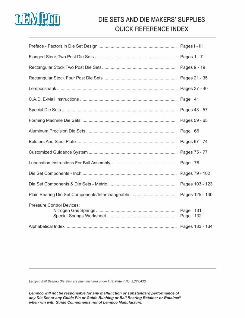
DIE SETS AND DIE MAKERS’ SUPPLIESQUICK REFERENCE INDEX
Preface - Factors in Die Set Design ................................................................ Pages I - III
Flanged Stock Two Post Die Sets ................................................................... Pages 1 - 7
Rectangular Stock Two Post Die Sets ............................................................. Pages 9 - 19
Rectangular Stock Four Post Die Sets ............................................................ Pages 21 - 35
Lempcoshank .................................................................................................. Pages 37 - 40
C.A.D. E-Mail Instructions ............................................................................... Page 41
Special Die Sets .............................................................................................. Pages 43 - 57
Forming Machine Die Sets .............................................................................. Pages 59 - 65
Aluminum Precision Die Sets .......................................................................... Page 66
Bolsters And Steel Plate .................................................................................. Pages 67 - 74
Customized Guidance System ........................................................................ Pages 75 - 77
Lubrication Instructions For Ball Assembly...................................................... Page 78
Die Set Components - Inch ............................................................................. Pages 79 - 102
Die Set Components & Die Sets - Metric ........................................................ Pages 103 - 123
Plain Bearing Die Set Components/Interchangeable ...................................... Pages 125 - 130
Pressure Control Devices:Nitrogen Gas Springs .................................................................. Page 131Special Springs Worksheet ......................................................... Page 132
Alphabetical Index ........................................................................................... Pages 133 - 134
Lempco Ball Bearing Die Sets are manufactured under U.S. Patent No. 2,774,430.
Lempco will not be responsible for any malfunction or substandard performance ofany Die Set or any Guide Pin or Guide Bushing or Ball Bearing Retainer or Rotainer®
when run with Guide Components not of Lempco Manufacture.
FACTORS IN DIE SET DESIGN
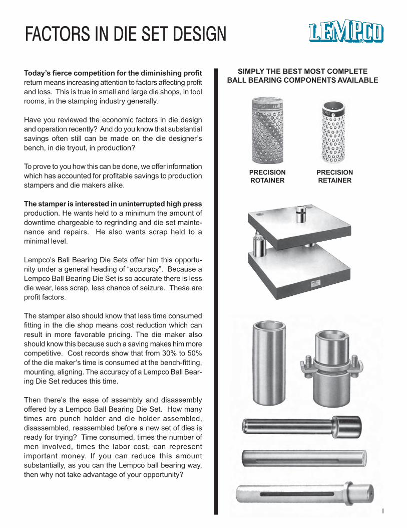
SIMPLY THE BEST MOST COMPLETEBALL BEARING COMPONENTS AVAILABLE
PRECISIONROTAINER
PRECISIONRETAINER
I
Today’s fierce competition for the diminishing profitreturn means increasing attention to factors affecting profitand loss. This is true in small and large die shops, in toolrooms, in the stamping industry generally.
Have you reviewed the economic factors in die designand operation recently? And do you know that substantialsavings often still can be made on the die designer’sbench, in die tryout, in production?
To prove to you how this can be done, we offer informationwhich has accounted for profitable savings to productionstampers and die makers alike.
The stamper is interested in uninterrupted high pressproduction. He wants held to a minimum the amount ofdowntime chargeable to regrinding and die set mainte-nance and repairs. He also wants scrap held to aminimal level.
Lempco’s Ball Bearing Die Sets offer him this opportu-nity under a general heading of “accuracy”. Because aLempco Ball Bearing Die Set is so accurate there is lessdie wear, less scrap, less chance of seizure. These areprofit factors.
The stamper also should know that less time consumedfitting in the die shop means cost reduction which canresult in more favorable pricing. The die maker alsoshould know this because such a saving makes him morecompetitive. Cost records show that from 30% to 50%of the die maker’s time is consumed at the bench-fitting,mounting, aligning. The accuracy of a Lempco Ball Bear-ing Die Set reduces this time.
Then there’s the ease of assembly and disassemblyoffered by a Lempco Ball Bearing Die Set. How manytimes are punch holder and die holder assembled,disassembled, reassembled before a new set of dies isready for trying? Time consumed, times the number ofmen involved, times the labor cost, can representimportant money. If you can reduce this amountsubstantially, as you can the Lempco ball bearing way,then why not take advantage of your opportunity?
FACTORS IN DIE SET DESIGN
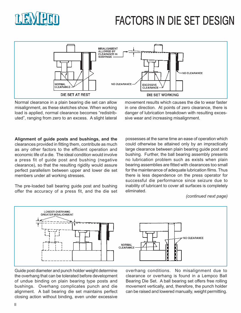
Normal clearance in a plain bearing die set can allowmisalignment, as these sketches show. When workingload is applied, normal clearance becomes “redistrib-uted”, ranging from zero to an excess. A slight lateral
Alignment of guide posts and bushings, and theclearances provided in fitting them, contribute as muchas any other factors to the efficient operation andeconomic life of a die. The ideal condition would involvea press fit of guide post and bushing (negativeclearance), so that the resulting rigidity would assureperfect parallelism between upper and lower die setmembers under all working stresses.
The pre-Ioaded ball bearing guide post and bushingoffer the accuracy of a press fit, and the die set
movement resuIts which causes the die to wear fasterin one direction. At points of zero clearance, there isdanger of lubrication breakdown with resulting exces-sive wear and increasing misalignment.
possesses at the same time an ease of operation whichcould otherwise be attained only by an impracticallylarge clearance between plain bearing guide post andbushing. Further, the ball bearing assembly presentsno lubrication problem such as exists when plainbearing assemblies are fitted with clearances too smallfor the maintenance of adequate lubrication films. Thusthere is less dependence on the press operator forsuccessful die performance since seizure due toinability of lubricant to cover all surfaces is completelyeliminated.
(continued next page)
Guide post diameter and punch holder weight determinethe overhang that can be tolerated before developmentof undue binding on plain bearing type posts andbushings. Overhang complicates punch and diealignment. A ball bearing die set maintains perfectclosing action without binding, even under excessive
overhang conditions. No misalignment due toclearance or overhang is found in a Lempco BallBearing Die Set. A ball bearing set offers free rollingmovement vertically, and, therefore, the punch holdercan be raised and lowered manually, weight permitting.
II
FACTORS IN DIE SET DESIGN
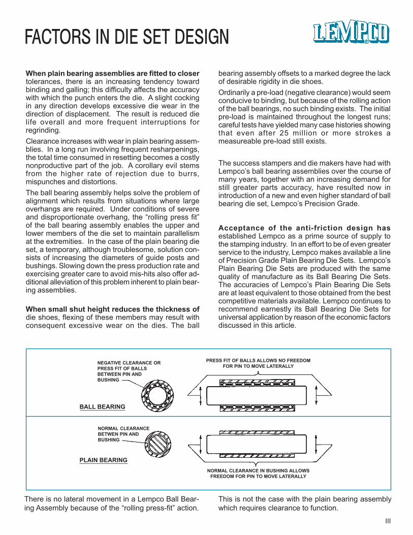
PRESS FIT OF BALLS ALLOWS NO FREEDOMFOR PIN TO MOVE LATERALLY
NORMAL CLEARANCE IN BUSHING ALLOWSFREEDOM FOR PIN TO MOVE LATERALLY
NEGATIVE CLEARANCE ORPRESS FIT OF BALLSBETWEEN PIN ANDBUSHING
NORMAL CLEARANCEBETWEN PIN ANDBUSHING
BALL BEARING
PLAIN BEARING
When plain bearing assemblies are fitted to closertolerances, there is an increasing tendency towardbinding and galling; this difficulty affects the accuracywith which the punch enters the die. A slight cockingin any direction develops excessive die wear in thedirection of displacement. The result is reduced dielife overall and more frequent interruptions forregrinding.Clearance increases with wear in plain bearing assem-blies. In a long run involving frequent resharpenings,the totaI time consumed in resetting becomes a costlynonproductive part of the job. A corollary eviI stemsfrom the higher rate of rejection due to burrs,mispunches and distortions.The ball bearing assembly helps solve the problem ofalignment which results from situations where largeoverhangs are required. Under conditions of severeand disproportionate overhang, the “rolling press fit”of the ball bearing assembly enables the upper andlower members of the die set to maintain parallelismat the extremities. In the case of the plain bearing dieset, a temporary, although troublesome, solution con-sists of increasing the diameters of guide posts andbushings. Slowing down the press production rate andexercising greater care to avoid mis-hits also offer ad-ditional alleviation of this problem inherent to plain bear-ing assemblies.
When small shut height reduces the thickness ofdie shoes, flexing of these members may result withconsequent excessive wear on the dies. The ball
bearing assembly offsets to a marked degree the lackof desirable rigidity in die shoes.Ordinarily a pre-load (negative clearance) would seemconducive to binding, but because of the rolling actionof the ball bearings, no such binding exists. The initialpre-load is maintained throughout the longest runs;careful tests have yielded many case histories showingthat even after 25 million or more strokes ameasureable pre-load stiII exists.
The success stampers and die makers have had withLempco’s ball bearing assemblies over the course ofmany years, together with an increasing demand forstill greater parts accuracy, have resulted now inintroduction of a new and even higher standard of ballbearing die set, Lempco’s Precision Grade.
Acceptance of the anti-friction design hasestablished Lempco as a prime source of supply tothe stamping industry. In an effort to be of even greaterservice to the industry, Lempco makes available a lineof Precision Grade Plain Bearing Die Sets. Lempco’sPlain Bearing Die Sets are produced with the samequality of manufacture as its Ball Bearing Die Sets.The accuracies of Lempco’s Plain Bearing Die Setsare at least equivalent to those obtained from the bestcompetitive materials available. Lempco continues torecommend earnestly its Ball Bearing Die Sets foruniversal application by reason of the economic factorsdiscussed in this article.
There is no lateral movement in a Lempco Ball Bear-ing Assembly because of the “rolling press-fit” action.
This is not the case with the plain bearing assemblywhich requires clearance to function.
III

IV
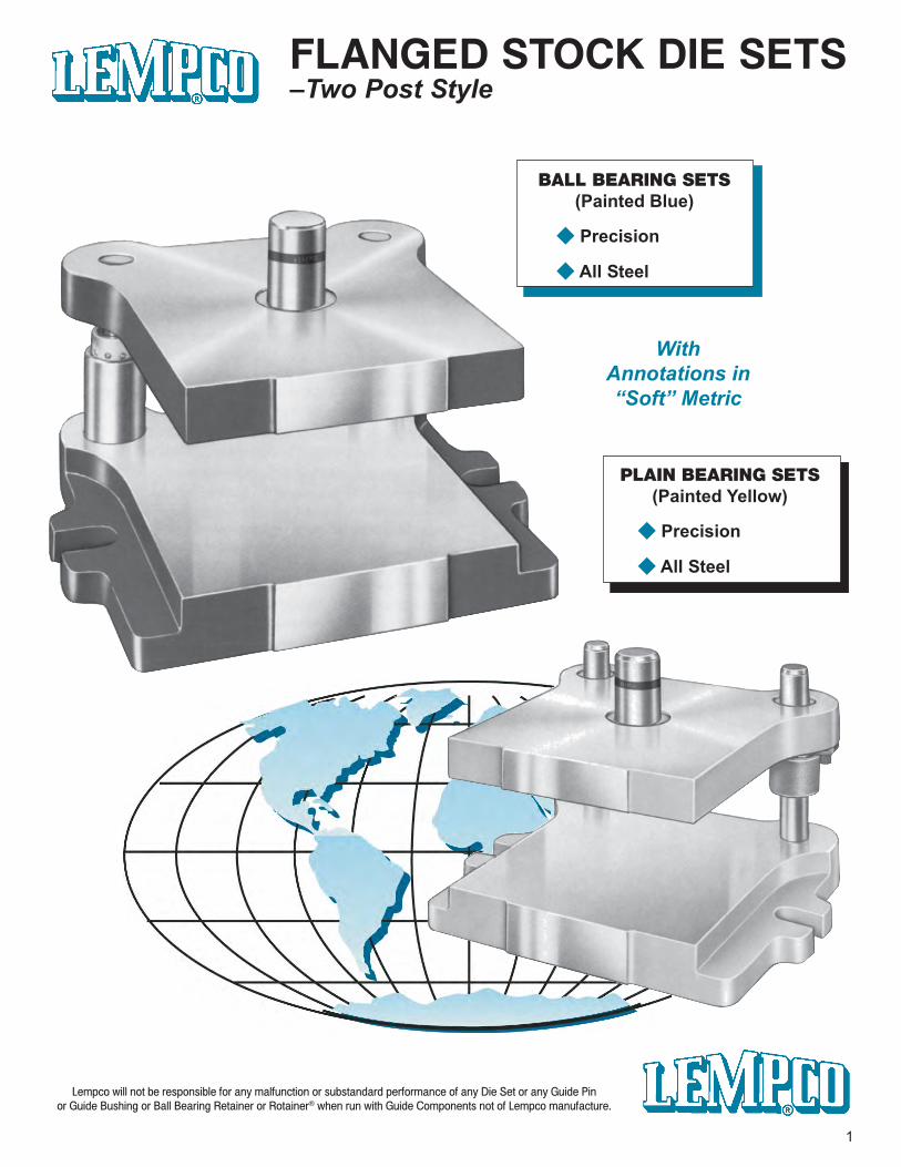
FLANGED STOCK DIE SETS–Two Post Style
Lempco will not be responsible for any malfunction or substandard performance of any Die Set or any Guide Pinor Guide Bushing or Ball Bearing Retainer or Rotainer® when run with Guide Components not of Lempco manufacture.
BALL BEARING SETS(Painted Blue)
◆ Precision
◆ All Steel
PLAIN BEARING SETS(Painted Yellow)
◆ Precision
◆ All Steel
WithAnnotations in“Soft” Metric
1
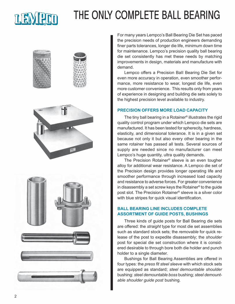
THE ONLY COMPLETE BALL BEARINGFor many years Lempco’s Ball Bearing Die Set has pacedthe precision needs of production engineers demandingfiner parts tolerances, longer die life, minimum down timefor maintenance. Lempco’s precision quality ball bearingdie set consistently has met these needs by matchingimprovements in design, materials and manufacture withdemand.
Lempco offers a Precision BaII Bearing Die Set foreven more accuracy in operation, even smoother perfor-mance, more resistance to wear, longest die life, evenmore customer convenience. This resuIts only from yearsof experience in designing and building die sets solely tothe highest precision level available to industry.
PRECISION OFFERS MORE LOAD CAPACITYThe tiny ball bearing in a Rotainer® illustrates the rigid
quality control program under which Lempco die sets aremanufactured. It has been tested for spherecity, hardness,elasticity, and dimensional tolerance. It is in a given setbecause not only it but also every other bearing in thesame rotainer has passed all tests. Several sources ofsupply are needed since no manufacturer can meetLempco’s huge quantity, ultra quality demands.
The Precision Rotainer® sleeve is an even tougheralloy for additional wear resistance. A Lempco die set ofthe Precision design provides longer operating life andsmoother performance through increased load capacityand resistance to adverse forces. For greater conveniencein disassembly a set screw keys the Rotainer® to the guidepost slot. The Precision Rotainer® sleeve is a silver colorwith blue stripes for quick visual identification.
BALL BEARING LINE INCLUDES COMPLETEASSORTMENT OF GUIDE POSTS, BUSHINGS
Three kinds of guide posts for Ball Bearing die setsare offered: the straight type for most die set assembliessuch as standard stock sets; the removable for quick re-lease of the post to expedite disassembly; the shoulderpost for special die set construction where it is consid-ered desirable to through bore both die holder and punchholder to a single diameter.
Bushings for Ball Bearing Assemblies are offered infour types: the press fit steel sleeve with which stock setsare equipped as standard; steel demountable shoulderbushing: steel demountable boss bushing; steel demount-able shoulder guide post bushing.
2
AND PLAIN BEARING DIE SET LINE
3
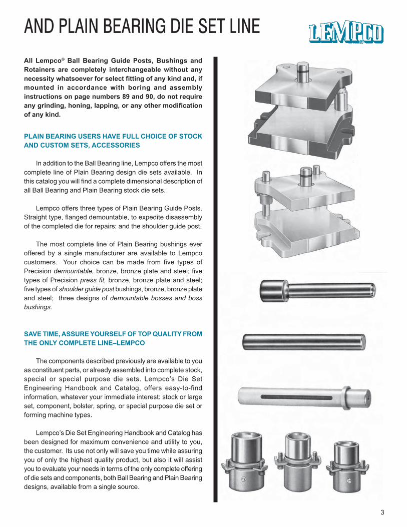
All Lempco® Ball Bearing Guide Posts, Bushings andRotainers are completely interchangeable without anynecessity whatsoever for select fitting of any kind and, ifmounted in accordance with boring and assemblyinstructions on page numbers 89 and 90, do not requireany grinding, honing, lapping, or any other modificationof any kind.
PLAIN BEARING USERS HAVE FULL CHOICE OF STOCKAND CUSTOM SETS, ACCESSORIES
In addition to the Ball Bearing line, Lempco offers the mostcomplete line of Plain Bearing design die sets available. Inthis catalog you will find a complete dimensional description ofall Ball Bearing and Plain Bearing stock die sets.
Lempco offers three types of Plain Bearing Guide Posts.Straight type, flanged demountable, to expedite disassemblyof the completed die for repairs; and the shoulder guide post.
The most complete line of Plain Bearing bushings everoffered by a single manufacturer are available to Lempcocustomers. Your choice can be made from five types ofPrecision demountable, bronze, bronze plate and steel; fivetypes of Precision press fit, bronze, bronze plate and steel;five types of shoulder guide post bushings, bronze, bronze plateand steel; three designs of demountable bosses and bossbushings.
SAVE TIME, ASSURE YOURSELF OF TOP QUALITY FROMTHE ONLY COMPLETE LINE–LEMPCO
The components described previously are available to youas constituent parts, or already assembled into complete stock,special or special purpose die sets. Lempco’s Die SetEngineering Handbook and Catalog, offers easy-to-findinformation, whatever your immediate interest: stock or largeset, component, bolster, spring, or special purpose die set orforming machine types.
Lempco’s Die Set Engineering Handbook and Catalog hasbeen designed for maximum convenience and utility to you,the customer. Its use not only will save you time while assuringyou of only the highest quality product, but also it will assistyou to evaluate your needs in terms of the only complete offeringof die sets and components, both Ball Bearing and Plain Bearingdesigns, available from a single source.
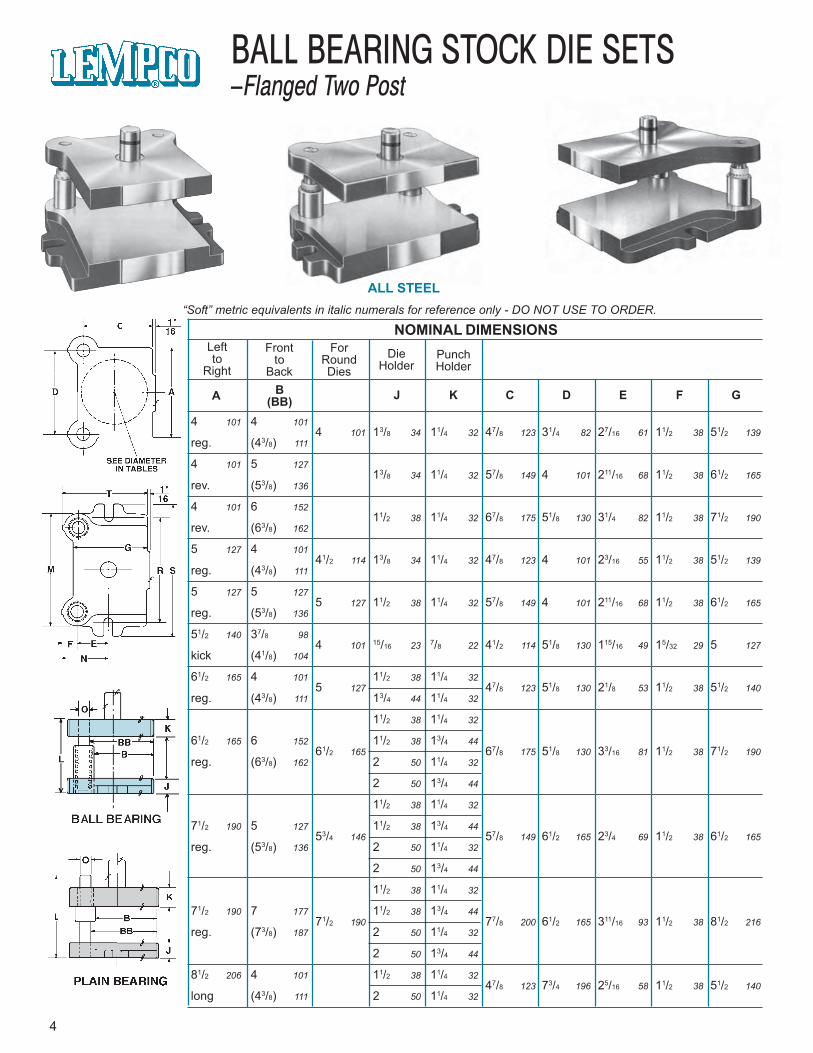
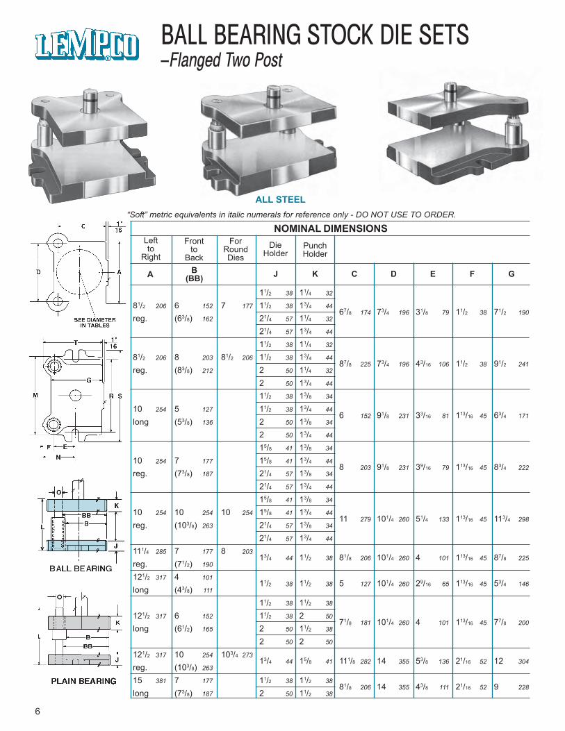
ALL STEEL“Soft” metric equivalents in italic numerals for reference only - DO NOT USE TO ORDER.
NOMINAL DIMENSIONSLeftto
Right
Frontto
Back
ForRoundDies
DieHolder
PunchHolder
A B(BB) J K C D E F G
4 101 4 1014 101 13/8 34 11/4 32 47/8 123 31/4 82 27/16 61 11/2 38 51/2 139
reg. (43/8) 111
4 101 5 12713/8 34 11/4 32 57/8 149 4 101 211/16 68 11/2 38 61/2 165
rev. (53/8) 136
4 101 6 15211/2 38 11/4 32 67/8 175 51/8 130 31/4 82 11/2 38 71/2 190
rev. (63/8) 162
5 127 4 10141/2 114 13/8 34 11/4 32 47/8 123 4 101 23/16 55 11/2 38 51/2 139
reg. (43/8) 111
5 127 5 1275 127 11/2 38 11/4 32 57/8 149 4 101 211/16 68 11/2 38 61/2 165
reg. (53/8) 136
51/2 140 37/8 984 101 15/16 23 7/8 22 41/2 114 51/8 130 115/16 49 15/32 29 5 127
kick (41/8) 104
61/2 165 4 101 11/2 38 11/4 325 127 47/8 123 51/8 130 21/8 53 11/2 38 51/2 140
reg. (43/8) 111 13/4 44 11/4 32
11/2 38 11/4 32
61/2 165 6 152 11/2 38 13/4 4461/2 165 67/8 175 51/8 130 33/16 81 11/2 38 71/2 190
reg. (63/8) 162 2 50 11/4 32
2 50 13/4 44
11/2 38 11/4 32
71/2 190 5 127 11/2 38 13/4 4453/4 146 57/8 149 61/2 165 23/4 69 11/2 38 61/2 165
reg. (53/8) 136 2 50 11/4 32
2 50 13/4 44
11/2 38 11/4 32
71/2 190 7 177 11/2 38 13/4 4471/2 190 77/8 200 61/2 165 311/16 93 11/2 38 81/2 216
reg. (73/8) 187 2 50 11/4 32
2 50 13/4 44
81/2 206 4 101 11/2 38 11/4 3247/8 123 73/4 196 25/16 58 11/2 38 51/2 140
long (43/8) 111 2 50 11/4 32
4
BALL BEARING STOCK DIE SETS–Flanged Two Post
61/4 158 315/16 100 1 25 6 152 71/2 190 63/8 162 51/4 133 0404-C1
7 177 43/16 106 1 25 6 152 73/4 196 73/8 187 51/4 133 0405-C1
81/8 206 43/4 120 1 25 6 152 81/8 206 83/8 212 51/4 133 0406-C1
7 177 311/16 93 1 25 63/4 171 81/4 209 63/8 162 51/4 133 0504-C1
7 177 43/16 106 1 25 63/4 171 81/4 209 73/8 187 51/4 133 0505-C1
77/16 189 33/32 78 3/4 19 63/4 171 73/4 196 521/32 144 41/2 114 0604-GA1
51/4 133 0604-C181/8 206 35/8 92 1 25 85/8 218 101/2 266 63/8 162
51/2 140 0604-C4
51/4 133 0606-C1
53/4 146 0606-C281/8 206 411/16 119 1 25 85/8 218 101/2 266 83/8 212
53/4 146 0606-C4
6 152 0606-C5
51/4 133 0705-C1
53/4 146 0705-C291/2 241 41/4 107 1 25 91/4 235 11 279 73/8 187
53/4 146 0705-C4
6 152 0705-C5
51/4 133 0707-C1
53/4 146 0707-C291/2 241 53/16 131 1 25 91/4 235 11 279 93/8 238
53/4 146 0707-C4
6 152 0707-C5
51/4 133 0804-C1103/4 273 313/16 96 1 25 105/8 269 121/2 317 63/8 162
53/4 146 0804-C4
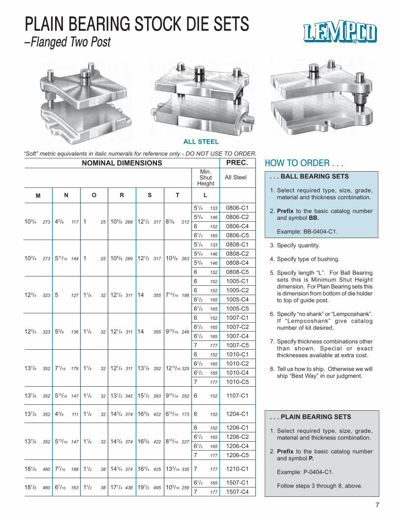
ALL STEEL
“Soft” metric equivalents in italic numerals for reference only - DO NOT USE TO ORDER.NOMINAL DIMENSIONS
M N O R S T L
Min.Shut
HeightAll Steel
PREC. HOW TO ORDER . . .. . . BALL BEARING SETS
1. Select required type, size, grade,material and thickness combination.
2. Prefix to the basic catalog numberand symbol BB.
Example: BB-0404-C1.
3. Specify quantity.
4. Specify type of bushing.
5. Specify length “L”. For Ball Bearingsets this is Minimum Shut Heightdimension. For Plain Bearing sets thisis dimension from bottom of die holderto top of guide post.
6. Specify “no shank” or “Lempcoshank”.If “Lempcoshank” give catalognumber of kit desired. For 0604-GA-1 andGD-1 kick press sets specify one ofthese: 1” diameter x 21/8” long or19/16” x 21/8”.
7. Specify thickness combinations otherthan shown. Special or exactthicknesses available at extra cost.
8. Tell us how to ship. Otherwise we willship “Best Way” in our judgment.
. . . PLAIN BEARING SETS
1. Select required type, size, grade,material and thickness combination.
2. Prefix to the basic catalog numberand symbol P.
Example: P-0404-C1.
Follow steps 3 through 8, above.
5
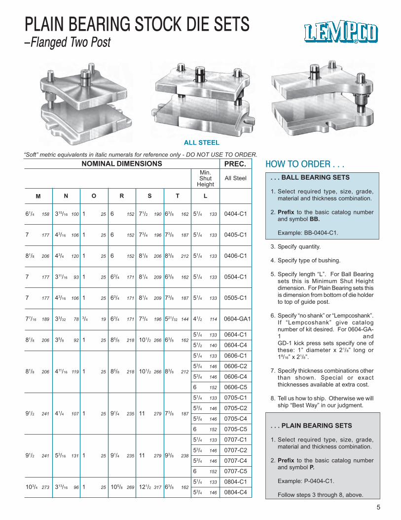
PLAIN BEARING STOCK DIE SETS–Flanged Two Post
ALL STEEL“Soft” metric equivalents in italic numerals for reference only - DO NOT USE TO ORDER.
NOMINAL DIMENSIONSLeftto
Right
Frontto
Back
ForRoundDies
DieHolder
PunchHolder
A B(BB) J K C D E F G
11/2 38 11/4 32
81/2 206 6 152 7 177 11/2 38 13/4 4467/8 174 73/4 196 31/8 79 11/2 38 71/2 190
reg. (63/8) 162 21/4 57 11/4 32
21/4 57 13/4 44
11/2 38 11/4 32
81/2 206 8 203 81/2 206 11/2 38 13/4 4487/8 225 73/4 196 43/16 106 11/2 38 91/2 241
reg. (83/8) 212 2 50 11/4 32
2 50 13/4 44
11/2 38 13/8 34
10 254 5 127 11/2 38 13/4 446 152 91/8 231 33/16 81 113/16 45 63/4 171
long (53/8) 136 2 50 13/8 34
2 50 13/4 44
15/8 41 13/8 34
10 254 7 177 15/8 41 13/4 448 203 91/8 231 39/16 79 113/16 45 83/4 222
reg. (73/8) 187 21/4 57 13/8 34
21/4 57 13/4 44
15/8 41 13/8 34
10 254 10 254 10 254 15/8 41 13/4 4411 279 101/4 260 51/4 133 113/16 45 113/4 298
reg. (103/8) 263 21/4 57 13/8 34
21/4 57 13/4 44
111/4 285 7 177 8 20313/4 44 11/2 38 81/8 206 101/4 260 4 101 113/16 45 87/8 225
reg. (71/2) 190
121/2 317 4 10111/2 38 11/2 38 5 127 101/4 260 29/16 65 113/16 45 53/4 146
long (43/8) 111
11/2 38 11/2 38
121/2 317 6 152 11/2 38 2 5071/8 181 101/4 260 4 101 113/16 45 77/8 200
long (61/2) 165 2 50 11/2 38
2 50 2 50
121/2 317 10 254 103/4 27313/4 44 15/8 41 111/8 282 14 355 53/8 136 21/16 52 12 304
reg. (103/8) 263
15 381 7 177 11/2 38 11/2 3881/8 206 14 355 43/8 111 21/16 52 9 228
long (73/8) 187 2 50 11/2 38
6
BALL BEARING STOCK DIE SETS–Flanged Two Post
ALL STEEL
“Soft” metric equivalents in italic numerals for reference only - DO NOT USE TO ORDER.
HOW TO ORDER . . .. . . BALL BEARING SETS
1. Select required type, size, grade,material and thickness combination.
2. Prefix to the basic catalog numberand symbol BB.
Example: BB-0404-C1.
3. Specify quantity.
4. Specify type of bushing.
5. Specify length “L”. For Ball Bearingsets this is Minimum Shut Heightdimension. For Plain Bearing sets thisis dimension from bottom of die holderto top of guide post.
6. Specify “no shank” or “Lempcoshank”.If “Lempcoshank” give catalognumber of kit desired.
7. Specify thickness combinations otherthan shown. Special or exactthicknesses available at extra cost.
8. Tell us how to ship. Otherwise we willship “Best Way” in our judgment.
. . . PLAIN BEARING SETS
1. Select required type, size, grade,material and thickness combination.
2. Prefix to the basic catalog numberand symbol P.
Example: P-0404-C1.
Follow steps 3 through 8, above.
7
PLAIN BEARING STOCK DIE SETS–Flanged Two Post
NOMINAL DIMENSIONS
M N O R S T L
PREC.Min.Shut
HeightAll Steel
51/4 133 0806-C153/4 146 0806-C2
103/4 273 45/8 117 1 25 105/8 269 121/2 317 83/8 2126 152 0806-C461/2 165 0806-C551/4 133 0808-C153/4 146 0808-C2
103/4 273 511/16 144 1 25 105/8 269 121/2 317 103/8 26353/4 146 0808-C46 152 0808-C56 152 1005-C16 152 1005-C2
123/4 323 5 127 11/4 32 121/4 311 14 355 713/16 19861/2 165 1005-C461/2 165 1005-C56 152 1007-C161/2 165 1007-C2
123/4 323 53/8 136 11/4 32 121/4 311 14 355 913/16 24961/2 165 1007-C47 177 1007-C56 152 1010-C161/2 165 1010-C2
137/8 352 71/16 179 11/4 32 121/4 311 137/8 352 1213/16 32561/2 165 1010-C47 177 1010-C5
137/8 352 513/16 147 11/4 32 131/2 342 151/2 393 915/16 252 6 152 1107-C1
137/8 352 43/8 111 11/4 32 143/4 374 165/8 422 613/16 173 6 152 1204-C1
6 152 1206-C161/2 165 1206-C2
137/8 352 513/16 147 11/4 32 143/4 374 165/8 422 815/16 22761/2 165 1206-C47 177 1206-C5
181/8 460 77/16 188 11/2 38 143/4 374 163/4 425 133/16 335 7 177 1210-C1
61/2 165 1507-C1181/8 460 67/16 163 11/2 38 171/4 438 191/2 495 103/16 259
7 177 1507-C4

8
Lempco will not be responsible for any malfunction or substandard performance of any Die Set or any Guide Pinor Guide Bushing or Ball Bearing Retainer or Rotainer® when run with Guide Components not of Lempco manufacture.
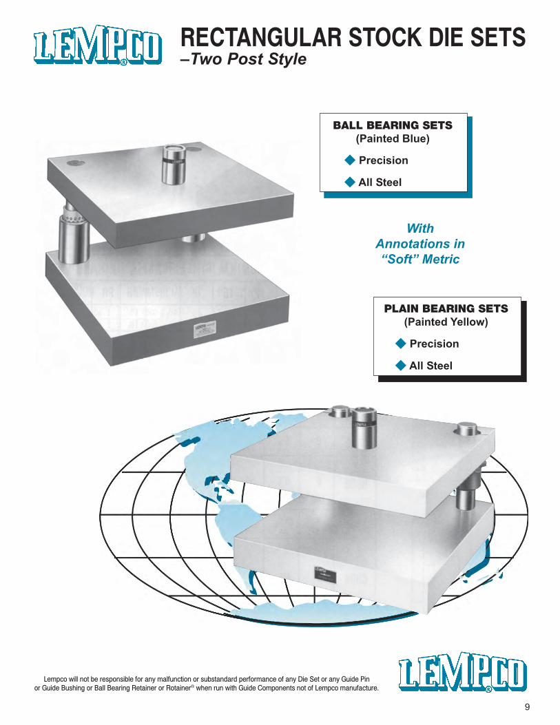
WithAnnotations in“Soft” Metric
9
BALL BEARING SETS(Painted Blue)
◆ Precision
◆ All Steel
PLAIN BEARING SETS(Painted Yellow)
◆ Precision
◆ All Steel
RECTANGULAR STOCK DIE SETS–Two Post Style
“Soft” metric equivalents in italic numerals for reference only - DO NOT USE TO ORDER.
10
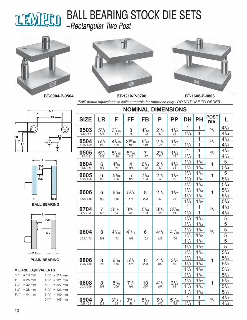
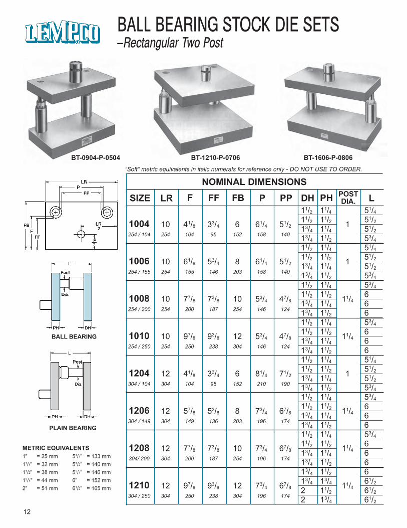
BALL BEARING STOCK DIE SETS–Rectangular Two Post
BT-0904-P-0504 BT-1210-P-0706 BT-1606-P-0806
BALL BEARING
PLAIN BEARING
METRIC EQUIVALENTS3/4" = 19 mm1" = 25 mm11/4" = 32 mm11/2" = 38 mm13/4" = 44 mm
41/2" = 114 mm43/4" = 121 mm5" = 127 mm51/4" = 133 mm51/2" = 140 mm53/4" = 146 mm
NOMINAL DIMENSIONS
SIZE LR F FF FB P PP DH PH LPOSTDIA.
0503 51/4 35/16 3 47/8 21/8 11/2 3/4133 / 84 133 84 76 123 53 38
0504 51/4 45/16 315/16 57/8 21/8 11/2 3/4133 / 109 133 109 100 149 53 38
0505 51/4 57/16 51/16 7 21/8 11/2 3/4133 / 131 133 138 128 177 53 38
0604 6 43/8 4 61/4 21/4 11/2 1152 / 111 152 111 101 158 57 38
0605 6 53/8 5 71/4 21/4 11/2 1152 / 136 152 136 127 184 57 38
0606 6 61/8 53/4 8 21/4 11/2 1152 / 155 152 155 146 203 57 38
0704 7 311/16 35/16 51/4 37/8 33/16 3/4177 / 93 177 93 84 133 98 81
0804 8 47/16 41/16 6 47/8 43/16 3/4203 / 112 203 112 103 152 123 106
0806 8 61/8 53/4 8 41/4 31/2 1203 / 155 203 155 146 203 107 88
0808 8 81/8 73/4 10 41/4 31/2 1203 / 206 203 206 196 254 107 88
0904 9 311/16 35/16 51/4 57/8 53/16 3/4228 / 93 228 93 88 133 149 132
1 1 41/4
11/4 1 43/4
1 1 41/211/4 1 43/4
1 1 41/2
11/4 1 43/4
11/4 11/4 511/2 11/4 51/4
11/4 11/4 511/2 11/4 51/4
11/2 11/4 51/4
11/2 11/2 51/2
13/4 11/4 51/2
13/4 11/2 53/4
1 1 41/211/4 1 43/4
11/4 11/4 511/4 11/2 511/2 11/4 511/2 11/2 513/4 11/4 513/4 11/2 511/2 11/4 51/4
11/2 11/2 51/2
13/4 11/4 51/2
13/4 11/2 53/4
11/2 11/4 51/4
11/2 11/2 51/2
13/4 11/4 51/2
13/4 11/2 53/4
1 1 41/2
11/4 1 43/4
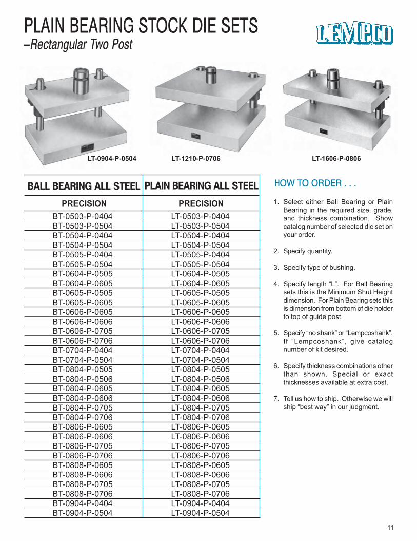
BT-0503-P-0404 LT-0503-P-0404BT-0503-P-0504 LT-0503-P-0504BT-0504-P-0404 LT-0504-P-0404BT-0504-P-0504 LT-0504-P-0504BT-0505-P-0404 LT-0505-P-0404BT-0505-P-0504 LT-0505-P-0504BT-0604-P-0505 LT-0604-P-0505BT-0604-P-0605 LT-0604-P-0605BT-0605-P-0505 LT-0605-P-0505BT-0605-P-0605 LT-0605-P-0605BT-0606-P-0605 LT-0606-P-0605BT-0606-P-0606 LT-0606-P-0606BT-0606-P-0705 LT-0606-P-0705BT-0606-P-0706 LT-0606-P-0706BT-0704-P-0404 LT-0704-P-0404BT-0704-P-0504 LT-0704-P-0504BT-0804-P-0505 LT-0804-P-0505BT-0804-P-0506 LT-0804-P-0506BT-0804-P-0605 LT-0804-P-0605BT-0804-P-0606 LT-0804-P-0606BT-0804-P-0705 LT-0804-P-0705BT-0804-P-0706 LT-0804-P-0706BT-0806-P-0605 LT-0806-P-0605BT-0806-P-0606 LT-0806-P-0606BT-0806-P-0705 LT-0806-P-0705BT-0806-P-0706 LT-0806-P-0706BT-0808-P-0605 LT-0808-P-0605BT-0808-P-0606 LT-0808-P-0606BT-0808-P-0705 LT-0808-P-0705BT-0808-P-0706 LT-0808-P-0706BT-0904-P-0404 LT-0904-P-0404BT-0904-P-0504 LT-0904-P-0504
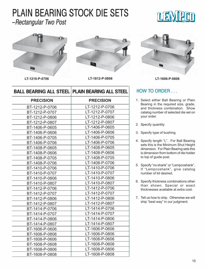
HOW TO ORDER . . .
1. Select either Ball Bearing or PlainBearing in the required size, grade,and thickness combination. Showcatalog number of selected die set onyour order.
2. Specify quantity.
3. Specify type of bushing.
4. Specify length “L”. For Ball Bearingsets this is the Minimum Shut Heightdimension. For Plain Bearing sets thisis dimension from bottom of die holderto top of guide post.
5. Specify “no shank” or “Lempcoshank”.If “Lempcoshank”, give catalognumber of kit desired.
6. Specify thickness combinations otherthan shown. Special or exactthicknesses available at extra cost.
7. Tell us how to ship. Otherwise we willship “best way” in our judgment.
11
PLAIN BEARING STOCK DIE SETS–Rectangular Two Post
LT-0904-P-0504 LT-1210-P-0706 LT-1606-P-0806
PRECISION PRECISION
PLAIN BEARING ALL STEELBALL BEARING ALL STEEL
“Soft” metric equivalents in italic numerals for reference only - DO NOT USE TO ORDER.
12
BALL BEARING STOCK DIE SETS–Rectangular Two Post
BT-0904-P-0504 BT-1210-P-0706 BT-1606-P-0806
BALL BEARING
PLAIN BEARING
METRIC EQUIVALENTS1" = 25 mm11/4" = 32 mm11/2" = 38 mm13/4" = 44 mm2" = 51 mm
51/4" = 133 mm51/2" = 140 mm53/4" = 146 mm6" = 152 mm61/2" = 165 mm
NOMINAL DIMENSIONSSIZE LR F FF FB P PP DH PH POST
DIA. L11/2 11/4 51/4
11/2 11/2 51/21004 10 41/8 33/4 6 61/4 51/2 113/4 11/4 51/2254 / 104 254 104 95 152 158 140 13/4 11/2 53/4
11/2 11/4 51/4
11/2 11/2 51/21006 10 61/8 53/4 8 61/4 51/2 113/4 11/4 51/2254 / 155 254 155 146 203 158 140 13/4 11/2 53/4
11/2 11/4 53/4
11/2 11/2 61008 10 77/8 73/8 10 53/4 47/8 11/413/4 11/4 6254 / 200 254 200 187 254 146 124 13/4 11/2 6
11/2 11/4 53/4
11/2 11/2 61010 10 97/8 93/8 12 53/4 47/8 11/413/4 11/4 6254 / 250 254 250 238 304 146 124 13/4 11/2 6
11/2 11/4 51/4
11/2 11/2 51/21204 12 41/8 33/4 6 81/4 71/2 113/4 11/4 51/2304 / 104 304 104 95 152 210 190 13/4 11/2 53/4
11/2 11/4 53/4
11/2 11/2 61206 12 57/8 53/8 8 73/4 67/8 11/413/4 11/4 6304 / 149 304 149 136 203 196 174 13/4 11/2 6
11/2 11/4 53/4
11/2 11/2 61208 12 77/8 73/8 10 73/4 67/8 11/413/4 11/4 6304/ 200 304 200 187 254 196 174 13/4 11/2 6
13/4 11/2 613/4 13/4 61/21210 12 97/8 93/8 12 73/4 67/8 11/42 11/2 61/2
304 / 250 304 250 238 304 196 174 2 13/4 61/2
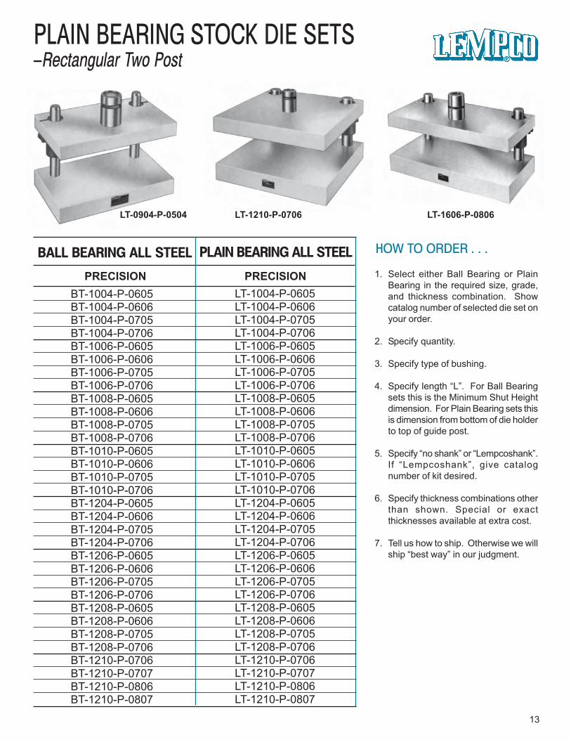
HOW TO ORDER . . .
1. Select either Ball Bearing or PlainBearing in the required size, grade,and thickness combination. Showcatalog number of selected die set onyour order.
2. Specify quantity.
3. Specify type of bushing.
4. Specify length “L”. For Ball Bearingsets this is the Minimum Shut Heightdimension. For Plain Bearing sets thisis dimension from bottom of die holderto top of guide post.
5. Specify “no shank” or “Lempcoshank”.If “Lempcoshank”, give catalognumber of kit desired.
6. Specify thickness combinations otherthan shown. Special or exactthicknesses available at extra cost.
7. Tell us how to ship. Otherwise we willship “best way” in our judgment.
13
PLAIN BEARING STOCK DIE SETS–Rectangular Two Post
LT-0904-P-0504 LT-1210-P-0706 LT-1606-P-0806
PRECISION PRECISION
PLAIN BEARING ALL STEELBALL BEARING ALL STEEL
LT-1004-P-0605LT-1004-P-0606LT-1004-P-0705LT-1004-P-0706LT-1006-P-0605LT-1006-P-0606LT-1006-P-0705LT-1006-P-0706LT-1008-P-0605LT-1008-P-0606LT-1008-P-0705LT-1008-P-0706LT-1010-P-0605LT-1010-P-0606LT-1010-P-0705LT-1010-P-0706LT-1204-P-0605LT-1204-P-0606LT-1204-P-0705LT-1204-P-0706LT-1206-P-0605LT-1206-P-0606LT-1206-P-0705LT-1206-P-0706LT-1208-P-0605LT-1208-P-0606LT-1208-P-0705LT-1208-P-0706LT-1210-P-0706LT-1210-P-0707LT-1210-P-0806LT-1210-P-0807
BT-1004-P-0605BT-1004-P-0606BT-1004-P-0705BT-1004-P-0706BT-1006-P-0605BT-1006-P-0606BT-1006-P-0705BT-1006-P-0706BT-1008-P-0605BT-1008-P-0606BT-1008-P-0705BT-1008-P-0706BT-1010-P-0605BT-1010-P-0606BT-1010-P-0705BT-1010-P-0706BT-1204-P-0605BT-1204-P-0606BT-1204-P-0705BT-1204-P-0706BT-1206-P-0605BT-1206-P-0606BT-1206-P-0705BT-1206-P-0706BT-1208-P-0605BT-1208-P-0606BT-1208-P-0705BT-1208-P-0706BT-1210-P-0706BT-1210-P-0707BT-1210-P-0806BT-1210-P-0807
“Soft” metric equivalents in italic numerals for reference only - DO NOT USE TO ORDER.
14
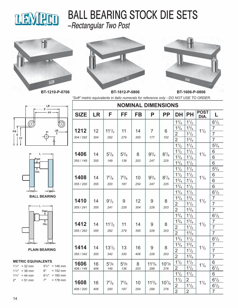
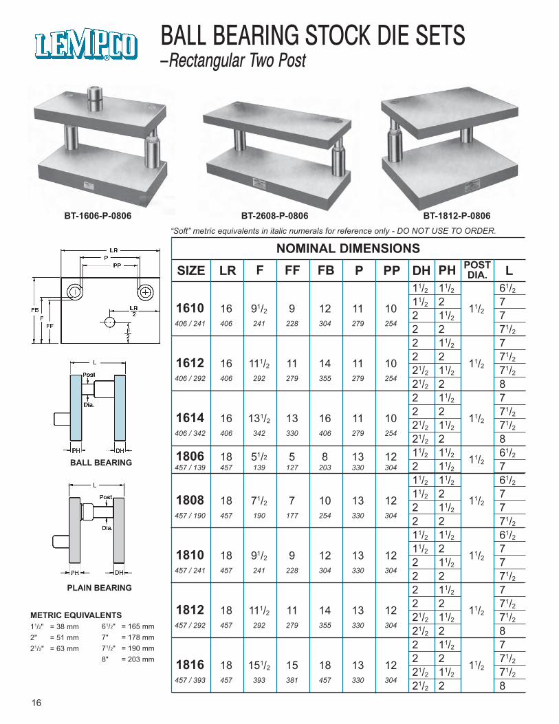
BALL BEARING STOCK DIE SETS–Rectangular Two Post
BT-1210-P-0706 BT-1812-P-0806 BT-1606-P-0806
BALL BEARING
PLAIN BEARING
METRIC EQUIVALENTS11/4" = 32 mm11/2" = 38 mm13/4" = 44 mm2" = 51 mm
53/4" = 146 mm6" = 152 mm61/2" = 165 mm7" = 178 mm
NOMINAL DIMENSIONSSIZE LR F FF FB P PP DH PH POST
DIA. L13/4 11/2 61/213/4 13/4 71212 12 111/2 11 14 7 6 11/22 11/2 7
304 / 292 304 292 279 355 177 152 2 13/4 711/2 11/4 53/411/2 11/2 61406 14 57/8 53/8 8 93/4 87/8 11/413/4 11/4 6
355 / 149 355 149 136 203 247 225 13/4 11/2 611/2 11/4 53/411/2 11/2 61408 14 77/8 73/8 10 93/4 87/8 11/413/4 11/4 6
355 / 200 355 200 187 254 247 225 13/4 11/2 613/4 11/2 61/213/4 13/4 71410 14 91/2 9 12 9 8 11/22 11/2 7
355 / 241 355 241 228 304 228 203 2 13/4 713/4 11/2 61/213/4 13/4 71412 14 111/2 11 14 9 8 11/22 11/2 7
355 / 292 355 292 279 355 228 203 2 13/4 713/4 11/2 61/213/4 13/4 71414 14 131/2 13 16 9 8 11/22 11/2 7
355 / 342 355 342 330 406 228 203 2 13/4 711/2 11/2 61606 16 57/8 53/8 8 113/4 107/8 11/4
406 / 149 406 149 136 203 298 276 2 11/2 61/211/2 11/2 611/2 2 61/21608 16 77/8 73/8 10 113/4 107/8 11/42 11/2 61/2
406 / 200 406 200 187 254 298 276 2 2 7
HOW TO ORDER . . .
1. Select either Ball Bearing or PlainBearing in the required size, grade,and thickness combination. Showcatalog number of selected die set onyour order.
2. Specify quantity.
3. Specify type of bushing.
4. Specify length “L”. For Ball Bearingsets this is the Minimum Shut Heightdimension. For Plain Bearing sets thisis dimension from bottom of die holderto top of guide post.
5. Specify “no shank” or “Lempcoshank”.If “Lempcoshank”, give catalognumber of kit desired.
6. Specify thickness combinations otherthan shown. Special or exactthicknesses available at extra cost.
7. Tell us how to ship. Otherwise we willship “best way” in our judgment.
15
PLAIN BEARING STOCK DIE SETS–Rectangular Two Post
LT-1210-P-0706 LT-1812-P-0806 LT-1606-P-0806
PRECISION PRECISION
PLAIN BEARING ALL STEELBALL BEARING ALL STEEL
BT-1212-P-0706BT-1212-P-0707BT-1212-P-0806BT-1212-P-0807BT-1406-P-0605BT-1406-P-0606BT-1406-P-0705BT-1406-P-0706BT-1408-P-0605BT-1408-P-0606BT-1408-P-0705BT-1408-P-0706BT-1410-P-0706BT-1410-P-0707BT-1410-P-0806BT-1410-P-0807BT-1412-P-0706BT-1412-P-0707BT-1412-P-0806BT-1412-P-0807BT-1414-P-0706BT-1414-P-0707BT-1414-P-0806BT-1414-P-0807BT-1606-P-0606BT-1606-P-0806BT-1608-P-0606BT-1608-P-0608BT-1608-P-0806BT-1608-P-0808
LT-1212-P-0706LT-1212-P-0707LT-1212-P-0806LT-1212-P-0807LT-1406-P-0605LT-1406-P-0606LT-1406-P-0705LT-1406-P-0706LT-1408-P-0605LT-1408-P-0606LT-1408-P-0705LT-1408-P-0706LT-1410-P-0706LT-1410-P-0707LT-1410-P-0806LT-1410-P-0807LT-1412-P-0706LT-1412-P-0707LT-1412-P-0806LT-1412-P-0807LT-1414-P-0706LT-1414-P-0707LT-1414-P-0806LT-1414-P-0807LT-1606-P-0606LT-1606-P-0806LT-1608-P-0606LT-1608-P-0608LT-1608-P-0806LT-1608-P-0808
“Soft” metric equivalents in italic numerals for reference only - DO NOT USE TO ORDER.
16
BALL BEARING STOCK DIE SETS–Rectangular Two Post
BT-2608-P-0806 BT-1812-P-0806BT-1606-P-0806
BALL BEARING
PLAIN BEARING
METRIC EQUIVALENTS11/2" = 38 mm2" = 51 mm21/2" = 63 mm
61/2" = 165 mm7" = 178 mm71/2" = 190 mm8" = 203 mm
NOMINAL DIMENSIONSSIZE LR F FF FB P PP DH PH POST
DIA. L11/2 11/2 61/211/2 2 71610 16 91/2 9 12 11 10 11/22 11/2 7
406 / 241 406 241 228 304 279 254 2 2 71/22 11/2 72 2 71/21612 16 111/2 11 14 11 10 11/221/2 11/2 71/2
406 / 292 406 292 279 355 279 254 21/2 2 82 11/2 72 2 71/21614 16 131/2 13 16 11 10 11/221/2 11/2 71/2
406 / 342 406 342 330 406 279 254 21/2 2 811/2 11/2 61/21806 18 51/2 5 8 13 12 11/2
457 / 139 457 139 127 203 330 304 2 11/2 711/2 11/2 61/211/2 2 71808 18 71/2 7 10 13 12 11/22 11/2 7
457 / 190 457 190 177 254 330 304 2 2 71/211/2 11/2 61/211/2 2 71810 18 91/2 9 12 13 12 11/22 11/2 7
457 / 241 457 241 228 304 330 304 2 2 71/22 11/2 72 2 71/21812 18 111/2 11 14 13 12 11/221/2 11/2 71/2
457 / 292 457 292 279 355 330 304 21/2 2 82 11/2 72 2 71/21816 18 151/2 15 18 13 12 11/221/2 11/2 71/2
457 / 393 457 393 381 457 330 304 21/2 2 8
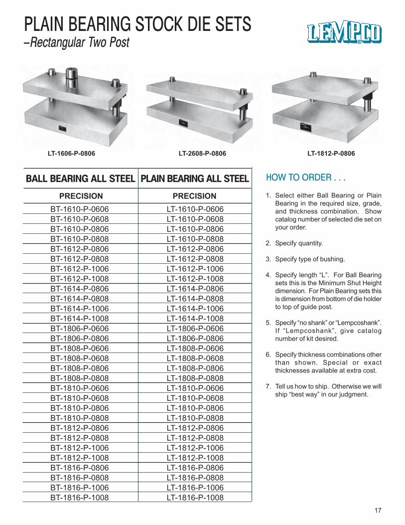
HOW TO ORDER . . .
1. Select either Ball Bearing or PlainBearing in the required size, grade,and thickness combination. Showcatalog number of selected die set onyour order.
2. Specify quantity.
3. Specify type of bushing.
4. Specify length “L”. For Ball Bearingsets this is the Minimum Shut Heightdimension. For Plain Bearing sets thisis dimension from bottom of die holderto top of guide post.
5. Specify “no shank” or “Lempcoshank”.If “Lempcoshank”, give catalognumber of kit desired.
6. Specify thickness combinations otherthan shown. Special or exactthicknesses available at extra cost.
7. Tell us how to ship. Otherwise we willship “best way” in our judgment.
17
PLAIN BEARING STOCK DIE SETS–Rectangular Two Post
LT-2608-P-0806 LT-1812-P-0806LT-1606-P-0806
PRECISION PRECISION
PLAIN BEARING ALL STEELBALL BEARING ALL STEEL
BT-1610-P-0606BT-1610-P-0608BT-1610-P-0806BT-1610-P-0808BT-1612-P-0806BT-1612-P-0808BT-1612-P-1006BT-1612-P-1008BT-1614-P-0806BT-1614-P-0808BT-1614-P-1006BT-1614-P-1008BT-1806-P-0606BT-1806-P-0806BT-1808-P-0606BT-1808-P-0608BT-1808-P-0806BT-1808-P-0808BT-1810-P-0606BT-1810-P-0608BT-1810-P-0806BT-1810-P-0808BT-1812-P-0806BT-1812-P-0808BT-1812-P-1006BT-1812-P-1008BT-1816-P-0806BT-1816-P-0808BT-1816-P-1006BT-1816-P-1008
LT-1610-P-0606LT-1610-P-0608LT-1610-P-0806LT-1610-P-0808LT-1612-P-0806LT-1612-P-0808LT-1612-P-1006LT-1612-P-1008LT-1614-P-0806LT-1614-P-0808LT-1614-P-1006LT-1614-P-1008LT-1806-P-0606LT-1806-P-0806LT-1808-P-0606LT-1808-P-0608LT-1808-P-0806LT-1808-P-0808LT-1810-P-0606LT-1810-P-0608LT-1810-P-0806LT-1810-P-0808LT-1812-P-0806LT-1812-P-0808LT-1812-P-1006LT-1812-P-1008LT-1816-P-0806LT-1816-P-0808LT-1816-P-1006LT-1816-P-1008
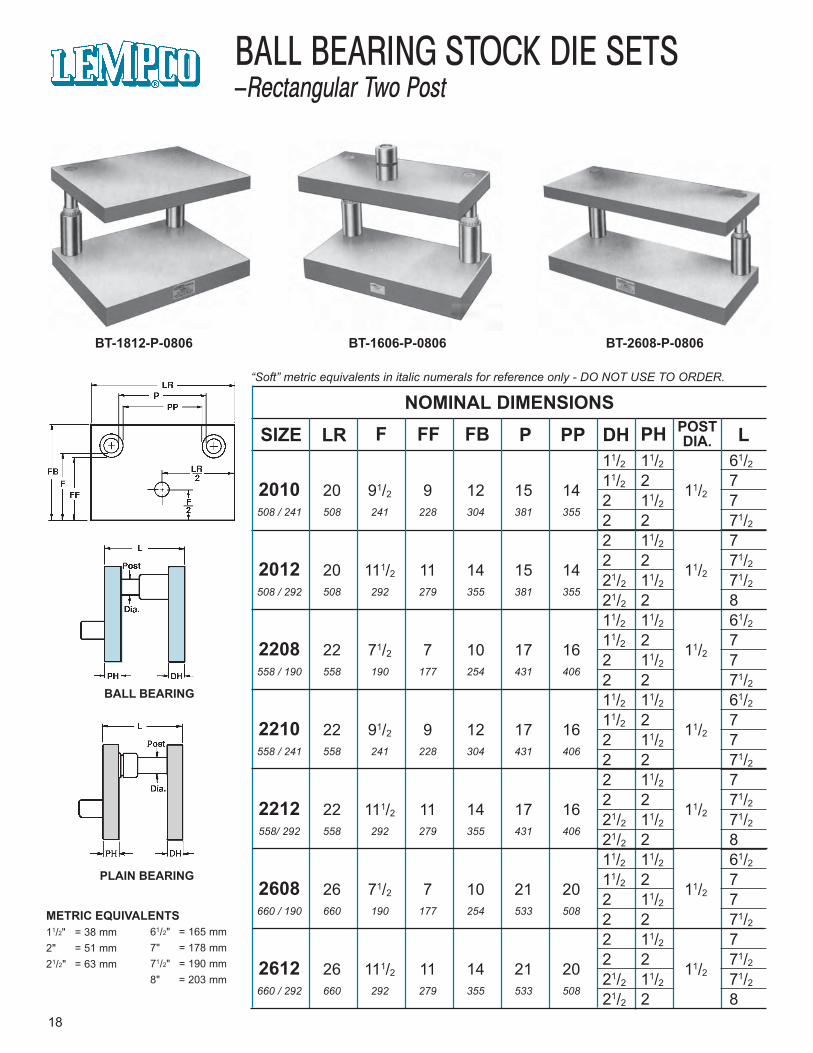
11/2 11/2 61/211/2 2 72010 20 91/2 9 12 15 14 11/22 11/2 7
508 / 241 508 241 228 304 381 355 2 2 71/22 11/2 72 2 71/22012 20 111/2 11 14 15 14 11/221/2 11/2 71/2
508 / 292 508 292 279 355 381 355 21/2 2 811/2 11/2 61/211/2 2 72208 22 71/2 7 10 17 16 11/22 11/2 7
558 / 190 558 190 177 254 431 406 2 2 71/211/2 11/2 61/211/2 2 72210 22 91/2 9 12 17 16 11/22 11/2 7
558 / 241 558 241 228 304 431 406 2 2 71/22 11/2 72 2 71/22212 22 111/2 11 14 17 16 11/221/2 11/2 71/2
558/ 292 558 292 279 355 431 406 21/2 2 811/2 11/2 61/211/2 2 72608 26 71/2 7 10 21 20 11/22 11/2 7
660 / 190 660 190 177 254 533 508 2 2 71/22 11/2 72 2 71/22612 26 111/2 11 14 21 20 11/221/2 11/2 71/2
660 / 292 660 292 279 355 533 508 21/2 2 8
“Soft” metric equivalents in italic numerals for reference only - DO NOT USE TO ORDER.
18
BALL BEARING STOCK DIE SETS–Rectangular Two Post
BT-2608-P-0806BT-1812-P-0806 BT-1606-P-0806
BALL BEARING
PLAIN BEARING
METRIC EQUIVALENTS11/2" = 38 mm2" = 51 mm21/2" = 63 mm
61/2" = 165 mm7" = 178 mm71/2" = 190 mm8" = 203 mm
NOMINAL DIMENSIONSSIZE LR F FF FB P PP DH PH POST
DIA. L
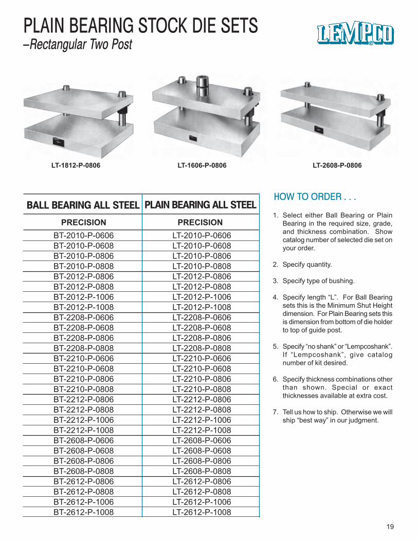
BT-2010-P-0606 LT-2010-P-0606BT-2010-P-0608 LT-2010-P-0608BT-2010-P-0806 LT-2010-P-0806BT-2010-P-0808 LT-2010-P-0808BT-2012-P-0806 LT-2012-P-0806BT-2012-P-0808 LT-2012-P-0808BT-2012-P-1006 LT-2012-P-1006BT-2012-P-1008 LT-2012-P-1008BT-2208-P-0606 LT-2208-P-0606BT-2208-P-0608 LT-2208-P-0608BT-2208-P-0806 LT-2208-P-0806BT-2208-P-0808 LT-2208-P-0808BT-2210-P-0606 LT-2210-P-0606BT-2210-P-0608 LT-2210-P-0608BT-2210-P-0806 LT-2210-P-0806BT-2210-P-0808 LT-2210-P-0808BT-2212-P-0806 LT-2212-P-0806BT-2212-P-0808 LT-2212-P-0808BT-2212-P-1006 LT-2212-P-1006BT-2212-P-1008 LT-2212-P-1008BT-2608-P-0606 LT-2608-P-0606BT-2608-P-0608 LT-2608-P-0608BT-2608-P-0806 LT-2608-P-0806BT-2608-P-0808 LT-2608-P-0808BT-2612-P-0806 LT-2612-P-0806BT-2612-P-0808 LT-2612-P-0808BT-2612-P-1006 LT-2612-P-1006BT-2612-P-1008 LT-2612-P-1008
HOW TO ORDER . . .
1. Select either Ball Bearing or PlainBearing in the required size, grade,and thickness combination. Showcatalog number of selected die set onyour order.
2. Specify quantity.
3. Specify type of bushing.
4. Specify length “L”. For Ball Bearingsets this is the Minimum Shut Heightdimension. For Plain Bearing sets thisis dimension from bottom of die holderto top of guide post.
5. Specify “no shank” or “Lempcoshank”.If “Lempcoshank”, give catalognumber of kit desired.
6. Specify thickness combinations otherthan shown. Special or exactthicknesses available at extra cost.
7. Tell us how to ship. Otherwise we willship “best way” in our judgment.
19
PLAIN BEARING STOCK DIE SETS–Rectangular Two Post
LT-2608-P-0806LT-1812-P-0806 LT-1606-P-0806
PRECISION PRECISION
PLAIN BEARING ALL STEELBALL BEARING ALL STEEL

20
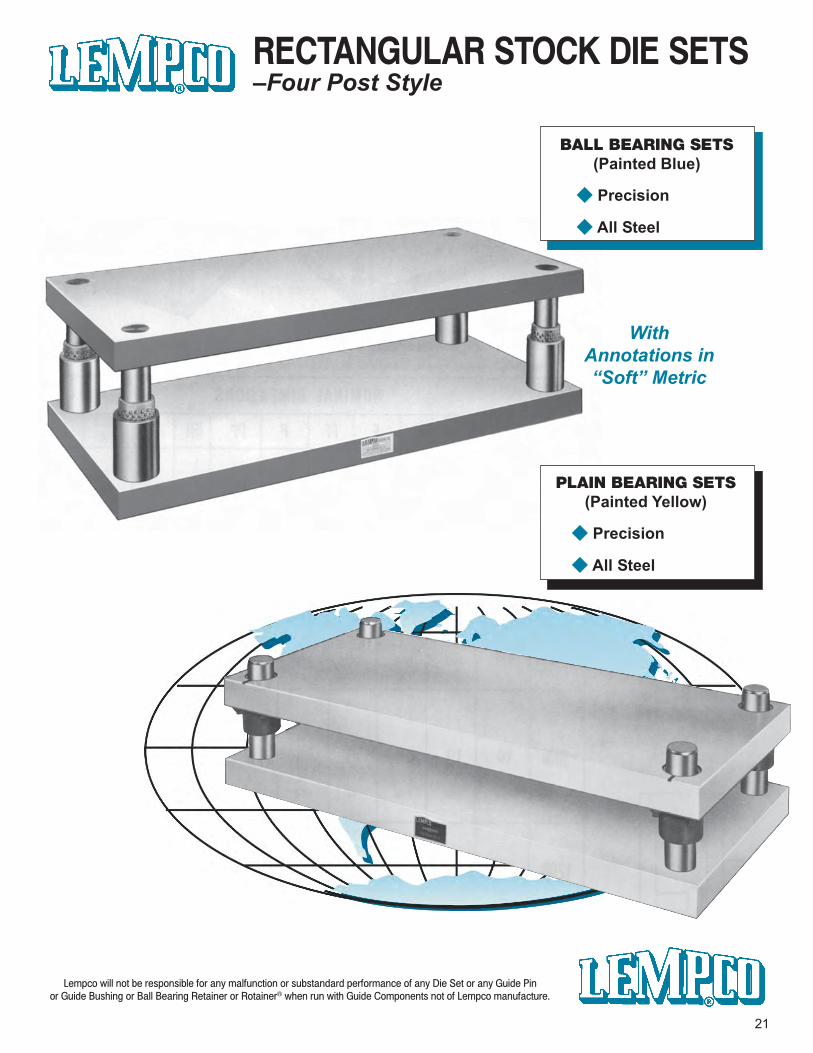
Lempco will not be responsible for any malfunction or substandard performance of any Die Set or any Guide Pinor Guide Bushing or Ball Bearing Retainer or Rotainer® when run with Guide Components not of Lempco manufacture.
WithAnnotations in“Soft” Metric
21
BALL BEARING SETS(Painted Blue)
◆ Precision
◆ All Steel
PLAIN BEARING SETS(Painted Yellow)
◆ Precision
◆ All Steel
RECTANGULAR STOCK DIE SETS–Four Post Style
“Soft” metric equivalents in italic numerals for reference only - DO NOT USE TO ORDER.
22
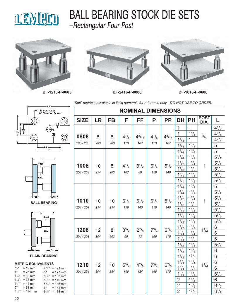
BALL BEARING STOCK DIE SETS–Rectangular Four Post
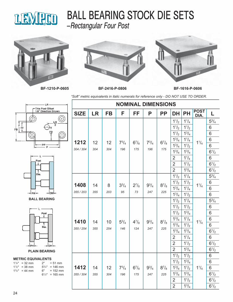
BF-1210-P-0605 BF-2416-P-0806 BF-1616-P-0606
BALL BEARING
PLAIN BEARING
NOMINAL DIMENSIONS
SIZE LR F FFFB P PP DH PH POSTDIA. L
METRIC EQUIVALENTS3/4" = 19 mm1" = 25 mm11/4" = 32 mm11/2" = 38 mm13/4" = 44 mm2" = 51 mm41/2" = 114 mm
43/4" = 121 mm5" = 127 mm51/4" = 133 mm51/2" = 140 mm53/4" = 146 mm6" = 152 mm61/2" = 165 mm
1 1 41/2
1 11/4 43/40808 8 8 47/8 43/16 47/8 43/163/411/4 1 43/4
203 / 203 203 203 123 107 123 107 11/4 11/4 511/4 11/4 511/4 11/2 51/4
11/2 11/4 51/41008 10 8 41/4 31/2 61/4 51/2 111/2 11/2 51/2254 / 203 254 203 107 89 158 140 13/4 11/4 51/2
13/4 11/2 53/4
11/4 11/4 511/4 11/2 51/4
11/2 11/4 51/41010 10 10 61/4 51/2 61/4 51/2 111/2 11/2 51/2254 / 254 254 254 158 140 158 140 13/4 11/4 51/2
13/4 11/2 53/4
11/2 11/4 53/4
11/2 11/2 61208 12 8 33/4 27/8 73/4 67/8 11/413/4 11/4 6304 / 203 304 203 95 73 196 175 13/4 11/2 6
11/2 11/4 53/4
11/2 11/2 611/2 13/4 613/4 11/4 61210 12 10 53/4 47/8 73/4 67/8 11/413/4 11/2 6
304 / 254 304 254 146 124 196 175 13/4 13/4 61/2
2 11/4 62 11/2 61/2
2 13/4 61/2
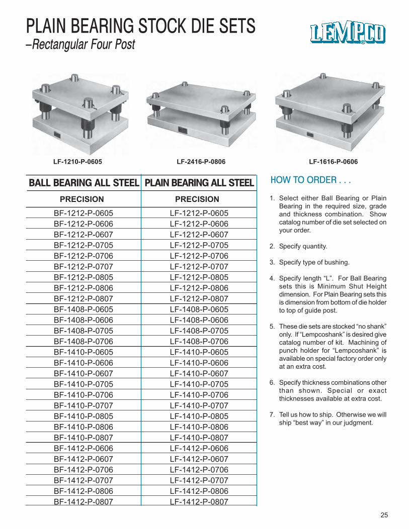
HOW TO ORDER . . .
1. Select either Ball Bearing or PlainBearing in the required size, gradeand thickness combination. Showcatalog number of die set selected onyour order.
2. Specify quantity.
3. Specify type of bushing.
4. Specify length “L”. For Ball Bearingsets this is Minimum Shut Heightdimension. For Plain Bearing sets thisis dimension from bottom of die holderto top of guide post.
5. These die sets are stocked “no shank”only. If “Lempcoshank” is desired givecatalog number of kit. Machining ofpunch holder for “Lempcoshank” isavailable on special factory order onlyat an extra cost.
6. Specify thickness combinations otherthan shown. Special or exactthicknesses available at extra cost.
7. Tell us how to ship. Otherwise we willship “best way” in our judgment.
23
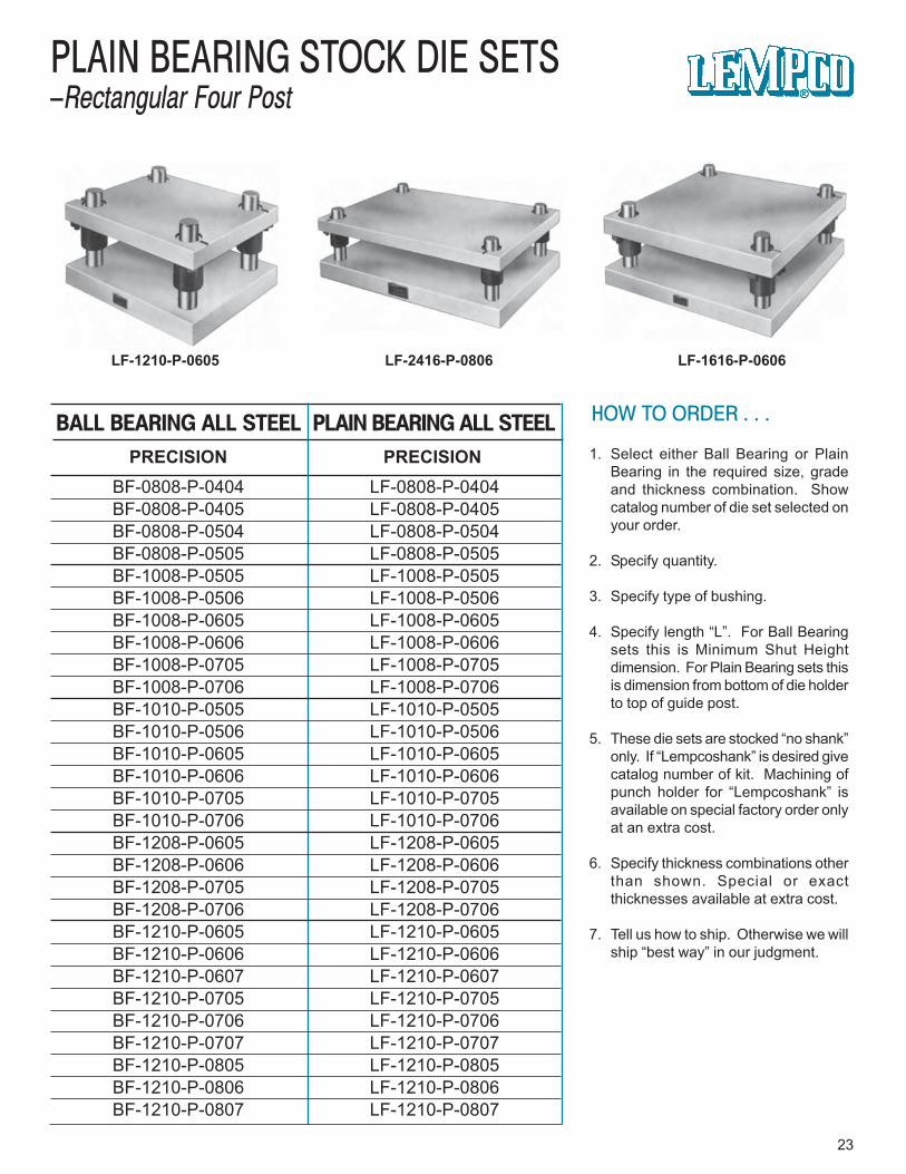
PLAIN BEARING STOCK DIE SETS–Rectangular Four Post
LF-1616-P-0606LF-1210-P-0605 LF-2416-P-0806
PRECISION PRECISION
PLAIN BEARING ALL STEELBALL BEARING ALL STEEL
BF-0808-P-0404 LF-0808-P-0404BF-0808-P-0405 LF-0808-P-0405BF-0808-P-0504 LF-0808-P-0504BF-0808-P-0505 LF-0808-P-0505BF-1008-P-0505 LF-1008-P-0505BF-1008-P-0506 LF-1008-P-0506BF-1008-P-0605 LF-1008-P-0605BF-1008-P-0606 LF-1008-P-0606BF-1008-P-0705 LF-1008-P-0705BF-1008-P-0706 LF-1008-P-0706BF-1010-P-0505 LF-1010-P-0505BF-1010-P-0506 LF-1010-P-0506BF-1010-P-0605 LF-1010-P-0605BF-1010-P-0606 LF-1010-P-0606BF-1010-P-0705 LF-1010-P-0705BF-1010-P-0706 LF-1010-P-0706BF-1208-P-0605 LF-1208-P-0605BF-1208-P-0606 LF-1208-P-0606BF-1208-P-0705 LF-1208-P-0705BF-1208-P-0706 LF-1208-P-0706BF-1210-P-0605 LF-1210-P-0605BF-1210-P-0606 LF-1210-P-0606BF-1210-P-0607 LF-1210-P-0607BF-1210-P-0705 LF-1210-P-0705BF-1210-P-0706 LF-1210-P-0706BF-1210-P-0707 LF-1210-P-0707BF-1210-P-0805 LF-1210-P-0805BF-1210-P-0806 LF-1210-P-0806BF-1210-P-0807 LF-1210-P-0807
11/2 11/4 53/411/2 11/2 611/2 13/4 613/4 11/4 61212 12 12 73/4 67/8 73/4 67/8 11/413/4 11/2 6
304 / 304 304 304 196 175 196 17513/4 13/4 61/22 11/4 62 11/2 61/22 13/4 61/211/2 11/4 53/411/2 11/2 61408 14 8 33/4 27/8 93/4 87/8 11/413/4 11/4 6
355 / 203 355 203 95 73 247 225 13/4 11/2 611/2 11/4 53/411/2 11/2 611/2 13/4 613/4 11/4 61410 14 10 53/4 47/8 93/4 87/8 11/413/4 11/2 6
355 / 254 355 254 146 124 247 225 13/4 13/4 61/22 11/4 62 11/2 61/22 13/4 61/211/2 11/2 611/2 13/4 6
1412 14 12 73/4 67/8 93/4 87/8 13/4 11/2 11/4 6355 / 304 355 304 196 175 247 225 13/4 13/4 61/2
2 11/2 61/22 13/4 61/2
“Soft” metric equivalents in italic numerals for reference only - DO NOT USE TO ORDER.
24
BALL BEARING STOCK DIE SETS–Rectangular Four Post
BF-1210-P-0605 BF-2416-P-0806 BF-1616-P-0606
BALL BEARING
PLAIN BEARING
NOMINAL DIMENSIONS
SIZE LR F FFFB P PP DH PH POSTDIA. L
METRIC EQUIVALENTS11/4" = 32 mm11/2" = 38 mm13/4" = 44 mm
2" = 51 mm53/4" = 146 mm6" = 152 mm61/2" = 165 mm
HOW TO ORDER . . .
1. Select either Ball Bearing or PlainBearing in the required size, gradeand thickness combination. Showcatalog number of die set selected onyour order.
2. Specify quantity.
3. Specify type of bushing.
4. Specify length “L”. For Ball Bearingsets this is Minimum Shut Heightdimension. For Plain Bearing sets thisis dimension from bottom of die holderto top of guide post.
5. These die sets are stocked “no shank”only. If “Lempcoshank” is desired givecatalog number of kit. Machining ofpunch holder for “Lempcoshank” isavailable on special factory order onlyat an extra cost.
6. Specify thickness combinations otherthan shown. Special or exactthicknesses available at extra cost.
7. Tell us how to ship. Otherwise we willship “best way” in our judgment.
25
PLAIN BEARING STOCK DIE SETS–Rectangular Four Post
LF-1616-P-0606LF-1210-P-0605 LF-2416-P-0806
PRECISION PRECISION
PLAIN BEARING ALL STEELBALL BEARING ALL STEEL
BF-1212-P-0605 LF-1212-P-0605BF-1212-P-0606 LF-1212-P-0606BF-1212-P-0607 LF-1212-P-0607BF-1212-P-0705 LF-1212-P-0705BF-1212-P-0706 LF-1212-P-0706BF-1212-P-0707 LF-1212-P-0707BF-1212-P-0805 LF-1212-P-0805BF-1212-P-0806 LF-1212-P-0806BF-1212-P-0807 LF-1212-P-0807BF-1408-P-0605 LF-1408-P-0605BF-1408-P-0606 LF-1408-P-0606BF-1408-P-0705 LF-1408-P-0705BF-1408-P-0706 LF-1408-P-0706BF-1410-P-0605 LF-1410-P-0605BF-1410-P-0606 LF-1410-P-0606BF-1410-P-0607 LF-1410-P-0607BF-1410-P-0705 LF-1410-P-0705BF-1410-P-0706 LF-1410-P-0706BF-1410-P-0707 LF-1410-P-0707BF-1410-P-0805 LF-1410-P-0805BF-1410-P-0806 LF-1410-P-0806BF-1410-P-0807 LF-1410-P-0807BF-1412-P-0606 LF-1412-P-0606BF-1412-P-0607 LF-1412-P-0607BF-1412-P-0706 LF-1412-P-0706BF-1412-P-0707 LF-1412-P-0707BF-1412-P-0806 LF-1412-P-0806BF-1412-P-0807 LF-1412-P-0807
“Soft” metric equivalents in italic numerals for reference only - DO NOT USE TO ORDER.
26
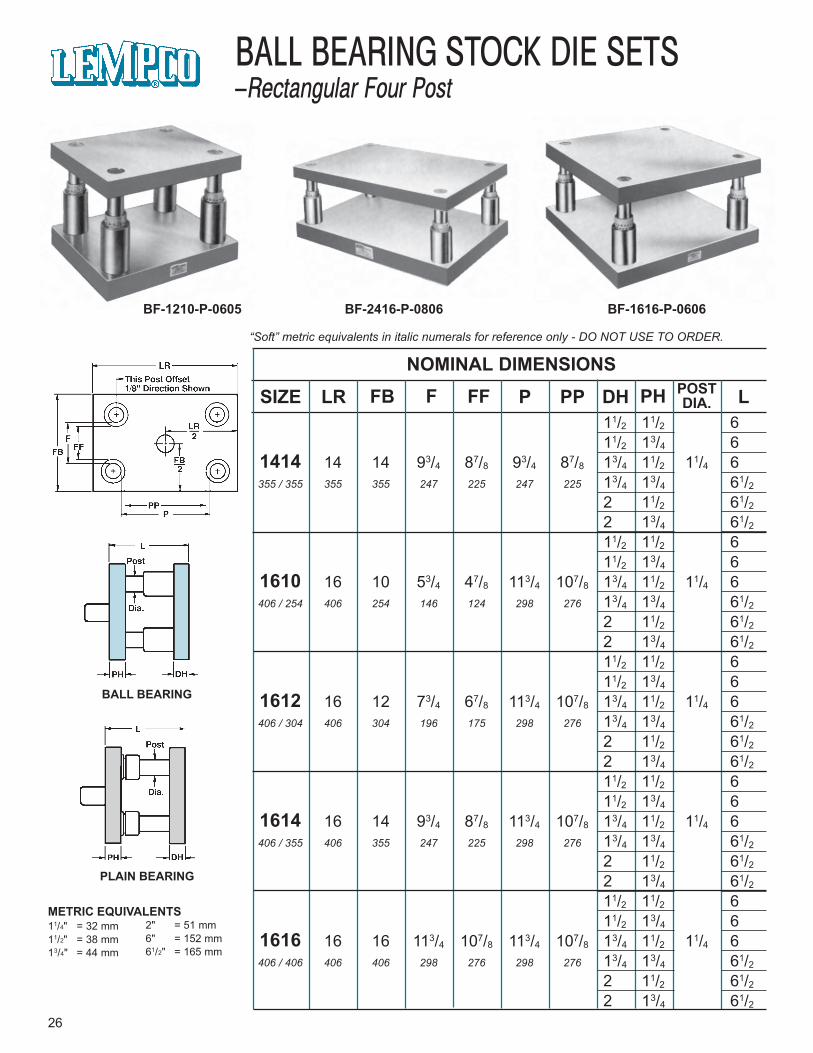
BALL BEARING STOCK DIE SETS–Rectangular Four Post
BF-1210-P-0605 BF-2416-P-0806 BF-1616-P-0606
BALL BEARING
PLAIN BEARING
NOMINAL DIMENSIONS
SIZE LR F FFFB P PP DH PH POSTDIA. L
METRIC EQUIVALENTS11/4" = 32 mm11/2" = 38 mm13/4" = 44 mm
2" = 51 mm6" = 152 mm61/2" = 165 mm
11/2 11/2 611/2 13/4 6
1414 14 14 93/4 87/8 93/4 87/8 13/4 11/2 11/4 6355 / 355 355 355 247 225 247 225 13/4 13/4 61/2
2 11/2 61/2
2 13/4 61/2
11/2 11/2 611/2 13/4 6
1610 16 10 53/4 47/8 113/4 107/8 13/4 11/2 11/4 6406 / 254 406 254 146 124 298 276 13/4 13/4 61/2
2 11/2 61/2
2 13/4 61/2
11/2 11/2 611/2 13/4 6
1612 16 12 73/4 67/8 113/4 107/8 13/4 11/2 11/4 6406 / 304 406 304 196 175 298 276 13/4 13/4 61/2
2 11/2 61/2
2 13/4 61/2
11/2 11/2 611/2 13/4 6
1614 16 14 93/4 87/8 113/4 107/8 13/4 11/2 11/4 6406 / 355 406 355 247 225 298 276 13/4 13/4 61/2
2 11/2 61/2
2 13/4 61/2
11/2 11/2 611/2 13/4 6
1616 16 16 113/4 107/8 113/4 107/8 13/4 11/2 11/4 6406 / 406 406 406 298 276 298 276 13/4 13/4 61/2
2 11/2 61/2
2 13/4 61/2
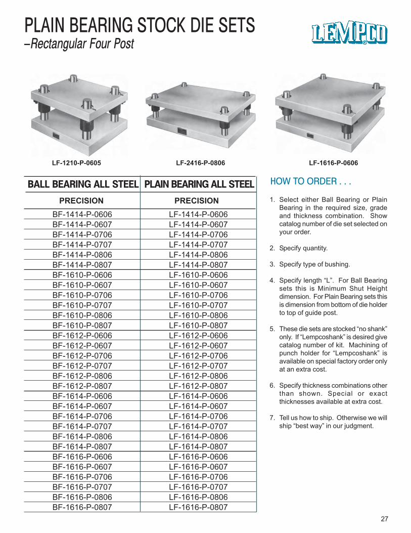
BF-1414-P-0606 LF-1414-P-0606BF-1414-P-0607 LF-1414-P-0607BF-1414-P-0706 LF-1414-P-0706BF-1414-P-0707 LF-1414-P-0707BF-1414-P-0806 LF-1414-P-0806BF-1414-P-0807 LF-1414-P-0807BF-1610-P-0606 LF-1610-P-0606BF-1610-P-0607 LF-1610-P-0607BF-1610-P-0706 LF-1610-P-0706BF-1610-P-0707 LF-1610-P-0707BF-1610-P-0806 LF-1610-P-0806BF-1610-P-0807 LF-1610-P-0807BF-1612-P-0606 LF-1612-P-0606BF-1612-P-0607 LF-1612-P-0607BF-1612-P-0706 LF-1612-P-0706BF-1612-P-0707 LF-1612-P-0707BF-1612-P-0806 LF-1612-P-0806BF-1612-P-0807 LF-1612-P-0807BF-1614-P-0606 LF-1614-P-0606BF-1614-P-0607 LF-1614-P-0607BF-1614-P-0706 LF-1614-P-0706BF-1614-P-0707 LF-1614-P-0707BF-1614-P-0806 LF-1614-P-0806BF-1614-P-0807 LF-1614-P-0807BF-1616-P-0606 LF-1616-P-0606BF-1616-P-0607 LF-1616-P-0607BF-1616-P-0706 LF-1616-P-0706BF-1616-P-0707 LF-1616-P-0707BF-1616-P-0806 LF-1616-P-0806BF-1616-P-0807 LF-1616-P-0807
HOW TO ORDER . . .
1. Select either Ball Bearing or PlainBearing in the required size, gradeand thickness combination. Showcatalog number of die set selected onyour order.
2. Specify quantity.
3. Specify type of bushing.
4. Specify length “L”. For Ball Bearingsets this is Minimum Shut Heightdimension. For Plain Bearing sets thisis dimension from bottom of die holderto top of guide post.
5. These die sets are stocked “no shank”only. If “Lempcoshank” is desired givecatalog number of kit. Machining ofpunch holder for “Lempcoshank” isavailable on special factory order onlyat an extra cost.
6. Specify thickness combinations otherthan shown. Special or exactthicknesses available at extra cost.
7. Tell us how to ship. Otherwise we willship “best way” in our judgment.
27
PLAIN BEARING STOCK DIE SETS–Rectangular Four Post
LF-1616-P-0606LF-1210-P-0605 LF-2416-P-0806
PRECISION PRECISION
PLAIN BEARING ALL STEELBALL BEARING ALL STEEL
“Soft” metric equivalents in italic numerals for reference only - DO NOT USE TO ORDER.
28
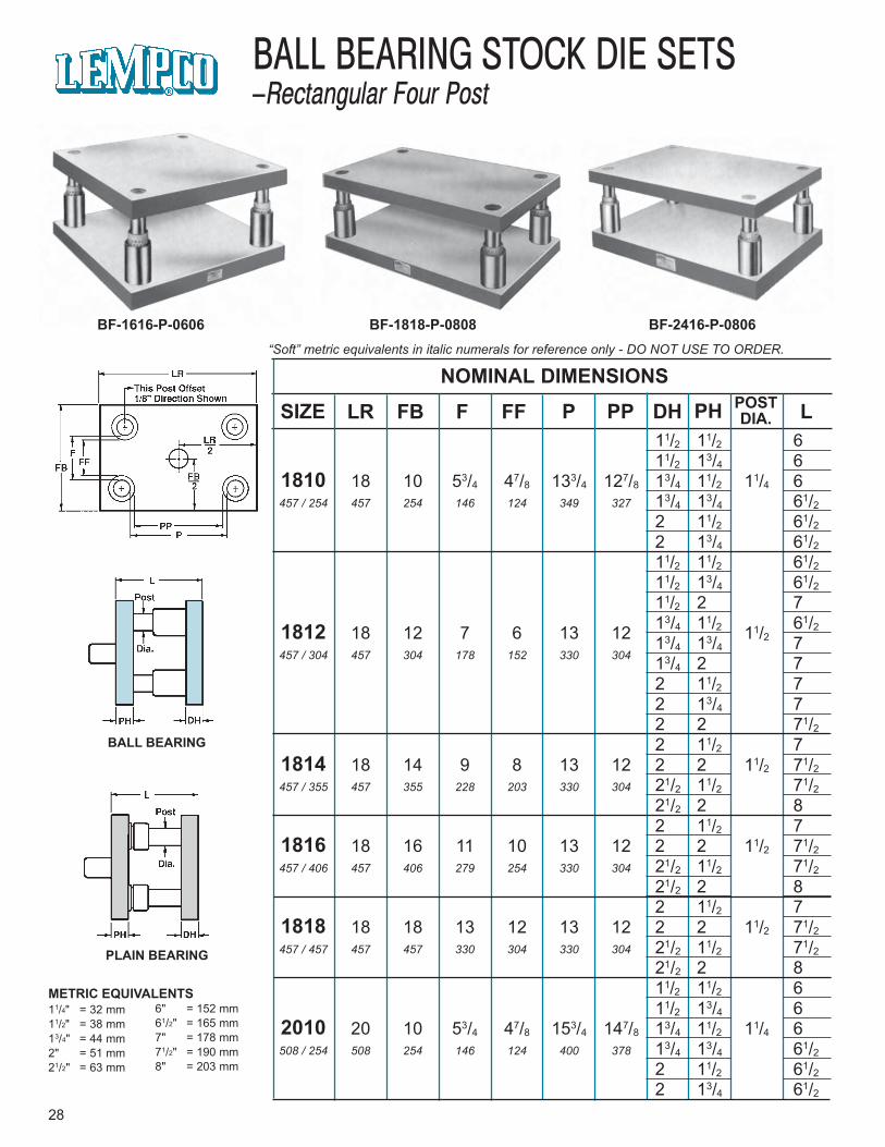
BALL BEARING STOCK DIE SETS–Rectangular Four Post
BF-1818-P-0808 BF-2416-P-0806BF-1616-P-0606
BALL BEARING
PLAIN BEARING
NOMINAL DIMENSIONS
SIZE LR F FFFB P PP DH PH POSTDIA. L
METRIC EQUIVALENTS11/4" = 32 mm11/2" = 38 mm13/4" = 44 mm2" = 51 mm21/2" = 63 mm
6" = 152 mm61/2" = 165 mm7" = 178 mm71/2" = 190 mm8" = 203 mm
11/2 11/2 611/2 13/4 6
1810 18 10 53/4 47/8 133/4 127/8 13/4 11/2 11/4 6457 / 254 457 254 146 124 349 327 13/4 13/4 61/2
2 11/2 61/22 13/4 61/211/2 11/2 61/211/2 13/4 61/211/2 2 713/4 11/2 61/21812 18 12 7 6 13 12 11/213/4 13/4 7
457 / 304 457 304 178 152 330 304 13/4 2 72 11/2 72 13/4 72 2 71/22 11/2 7
1814 18 14 9 8 13 12 2 2 11/2 71/2457 / 355 457 355 228 203 330 304 21/2 11/2 71/2
21/2 2 82 11/2 7
1816 18 16 11 10 13 12 2 2 11/2 71/2457 / 406 457 406 279 254 330 304 21/2 11/2 71/2
21/2 2 82 11/2 7
1818 18 18 13 12 13 12 2 2 11/2 71/2457 / 457 457 457 330 304 330 304 21/2 11/2 71/2
21/2 2 811/2 11/2 611/2 13/4 6
2010 20 10 53/4 47/8 153/4 147/8 13/4 11/2 11/4 6508 / 254 508 254 146 124 400 378 13/4 13/4 61/2
2 11/2 61/22 13/4 61/2
HOW TO ORDER . . .
1. Select either Ball Bearing or PlainBearing in the required size, gradeand thickness combination. Showcatalog number of die set selected onyour order.
2. Specify quantity.
3. Specify type of bushing.
4. Specify length “L”. For Ball Bearingsets this is Minimum Shut Heightdimension. For Plain Bearing sets thisis dimension from bottom of die holderto top of guide post.
5. These die sets are stocked “no shank”only. If “Lempcoshank” is desired givecatalog number of kit. Machining ofpunch holder for “Lempcoshank” isavailable on special factory order onlyat an extra cost.
6. Specify thickness combinations otherthan shown. Special or exactthicknesses available at extra cost.
7. Tell us how to ship. Otherwise we willship “best way” in our judgment.
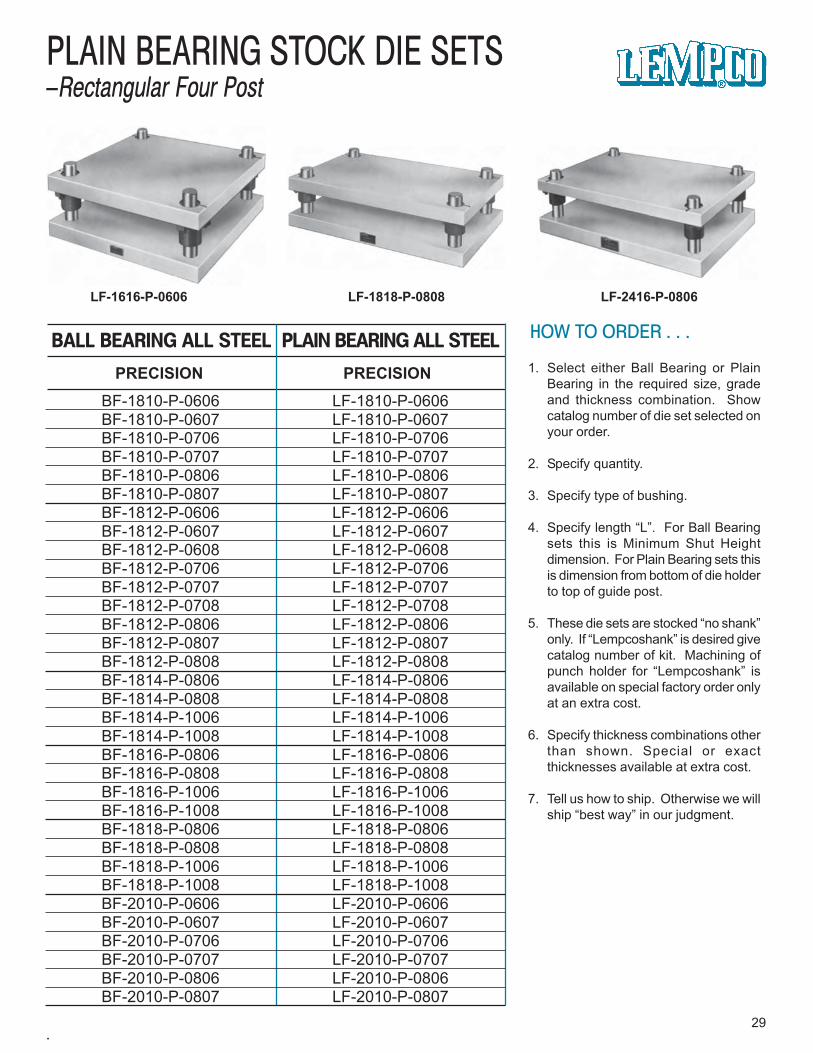
29
PLAIN BEARING STOCK DIE SETS–Rectangular Four Post
LF-1616-P-0606 LF-1818-P-0808 LF-2416-P-0806
PRECISION PRECISION
PLAIN BEARING ALL STEELBALL BEARING ALL STEEL
BF-1810-P-0606 LF-1810-P-0606BF-1810-P-0607 LF-1810-P-0607BF-1810-P-0706 LF-1810-P-0706BF-1810-P-0707 LF-1810-P-0707BF-1810-P-0806 LF-1810-P-0806BF-1810-P-0807 LF-1810-P-0807BF-1812-P-0606 LF-1812-P-0606BF-1812-P-0607 LF-1812-P-0607BF-1812-P-0608 LF-1812-P-0608BF-1812-P-0706 LF-1812-P-0706BF-1812-P-0707 LF-1812-P-0707BF-1812-P-0708 LF-1812-P-0708BF-1812-P-0806 LF-1812-P-0806BF-1812-P-0807 LF-1812-P-0807BF-1812-P-0808 LF-1812-P-0808BF-1814-P-0806 LF-1814-P-0806BF-1814-P-0808 LF-1814-P-0808BF-1814-P-1006 LF-1814-P-1006BF-1814-P-1008 LF-1814-P-1008BF-1816-P-0806 LF-1816-P-0806BF-1816-P-0808 LF-1816-P-0808BF-1816-P-1006 LF-1816-P-1006BF-1816-P-1008 LF-1816-P-1008BF-1818-P-0806 LF-1818-P-0806BF-1818-P-0808 LF-1818-P-0808BF-1818-P-1006 LF-1818-P-1006BF-1818-P-1008 LF-1818-P-1008BF-2010-P-0606 LF-2010-P-0606BF-2010-P-0607 LF-2010-P-0607BF-2010-P-0706 LF-2010-P-0706BF-2010-P-0707 LF-2010-P-0707BF-2010-P-0806 LF-2010-P-0806BF-2010-P-0807 LF-2010-P-0807
.
“Soft” metric equivalents in italic numerals for reference only - DO NOT USE TO ORDER.
30
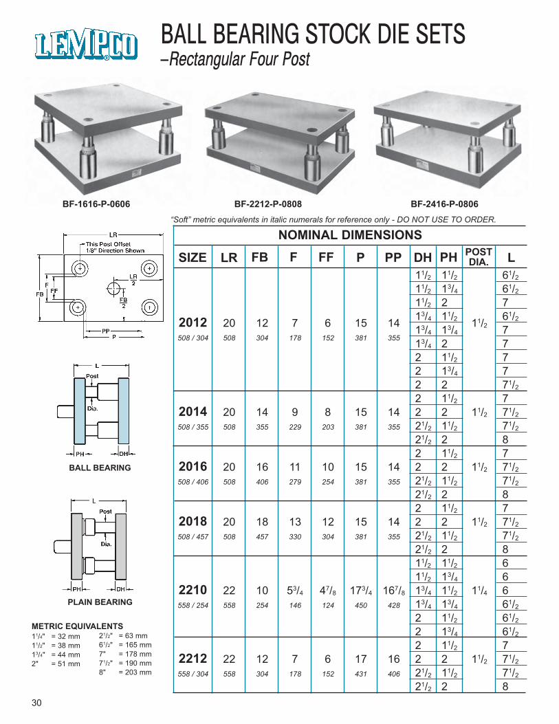
BALL BEARING STOCK DIE SETS–Rectangular Four Post
BF-2212-P-0808 BF-2416-P-0806BF-1616-P-0606
BALL BEARING
PLAIN BEARING
NOMINAL DIMENSIONS
SIZE LR F FFFB P PP DH PH POSTDIA. L
METRIC EQUIVALENTS11/4" = 32 mm11/2" = 38 mm13/4" = 44 mm2" = 51 mm
21/2" = 63 mm61/2" = 165 mm7" = 178 mm71/2" = 190 mm8" = 203 mm
11/2 11/2 61/2
11/2 13/4 61/2
11/2 2 713/4 11/2 61/22012 20 12 7 6 15 14 11/213/4 13/4 7
508 / 304 508 304 178 152 381 355 13/4 2 72 11/2 72 13/4 72 2 71/2
2 11/2 72014 20 14 9 8 15 14 2 2 11/2 71/2
508 / 355 508 355 229 203 381 355 21/2 11/2 71/2
21/2 2 82 11/2 7
2016 20 16 11 10 15 14 2 2 11/2 71/2
508 / 406 508 406 279 254 381 355 21/2 11/2 71/2
21/2 2 82 11/2 7
2018 20 18 13 12 15 14 2 2 11/2 71/2
508 / 457 508 457 330 304 381 355 21/2 11/2 71/2
21/2 2 811/2 11/2 611/2 13/4 6
2210 22 10 53/4 47/8 173/4 167/8 13/4 11/2 11/4 6558 / 254 558 254 146 124 450 428 13/4 13/4 61/2
2 11/2 61/2
2 13/4 61/2
2 11/2 72212 22 12 7 6 17 16 2 2 11/2 71/2
558 / 304 558 304 178 152 431 406 21/2 11/2 71/2
21/2 2 8
HOW TO ORDER . . .
1. Select either Ball Bearing or PlainBearing in the required size, gradeand thickness combination. Showcatalog number of die set selected onyour order.
2. Specify quantity.
3. Specify type of bushing.
4. Specify length “L”. For Ball Bearingsets this is Minimum Shut Heightdimension. For Plain Bearing sets thisis dimension from bottom of die holderto top of guide post.
5. These die sets are stocked “no shank”only. If “Lempcoshank” is desired givecatalog number of kit. Machining ofpunch holder for “Lempcoshank” isavailable on special factory order onlyat an extra cost.
6. Specify thickness combinations otherthan shown. Special or exactthicknesses available at extra cost.
7. Tell us how to ship. Otherwise we willship “best way” in our judgment.
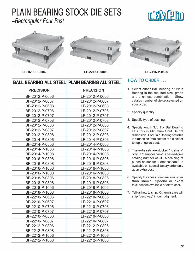
31
PLAIN BEARING STOCK DIE SETS–Rectangular Four Post
LF-1616-P-0606 LF-2212-P-0808 LF-2416-P-0806
PRECISION PRECISION
PLAIN BEARING ALL STEELBALL BEARING ALL STEEL
BF-2012-P-0606 LF-2012-P-0606BF-2012-P-0607 LF-2012-P-0607BF-2012-P-0608 LF-2012-P-0608BF-2012-P-0706 LF-2012-P-0706BF-2012-P-0707 LF-2012-P-0707BF-2012-P-0708 LF-2012-P-0708BF-2012-P-0806 LF-2012-P-0806BF-2012-P-0807 LF-2012-P-0807BF-2012-P-0808 LF-2012-P-0808BF-2014-P-0806 LF-2014-P-0806BF-2014-P-0808 LF-2014-P-0808BF-2014-P-1006 LF-2014-P-1006BF-2014-P-1008 LF-2014-P-1008BF-2016-P-0806 LF-2016-P-0806BF-2016-P-0808 LF-2016-P-0808BF-2016-P-1006 LF-2016-P-1006BF-2016-P-1008 LF-2016-P-1008BF-2018-P-0806 LF-2018-P-0806BF-2018-P-0808 LF-2018-P-0808BF-2018-P-1006 LF-2018-P-1006BF-2018-P-1008 LF-2018-P-1008BF-2210-P-0606 LF-2210-P-0606BF-2210-P-0607 LF-2210-P-0607BF-2210-P-0706 LF-2210-P-0706BF-2210-P-0707 LF-2210-P-0707BF-2210-P-0806 LF-2210-P-0806BF-2210-P-0807 LF-2210-P-0807BF-2212-P-0806 LF-2212-P-0806BF-2212-P-0808 LF-2212-P-0808BF-2212-P-1006 LF-2212-P-1006BF-2212-P-1008 LF-2212-P-1008
“Soft” metric equivalents in italic numerals for reference only - DO NOT USE TO ORDER.
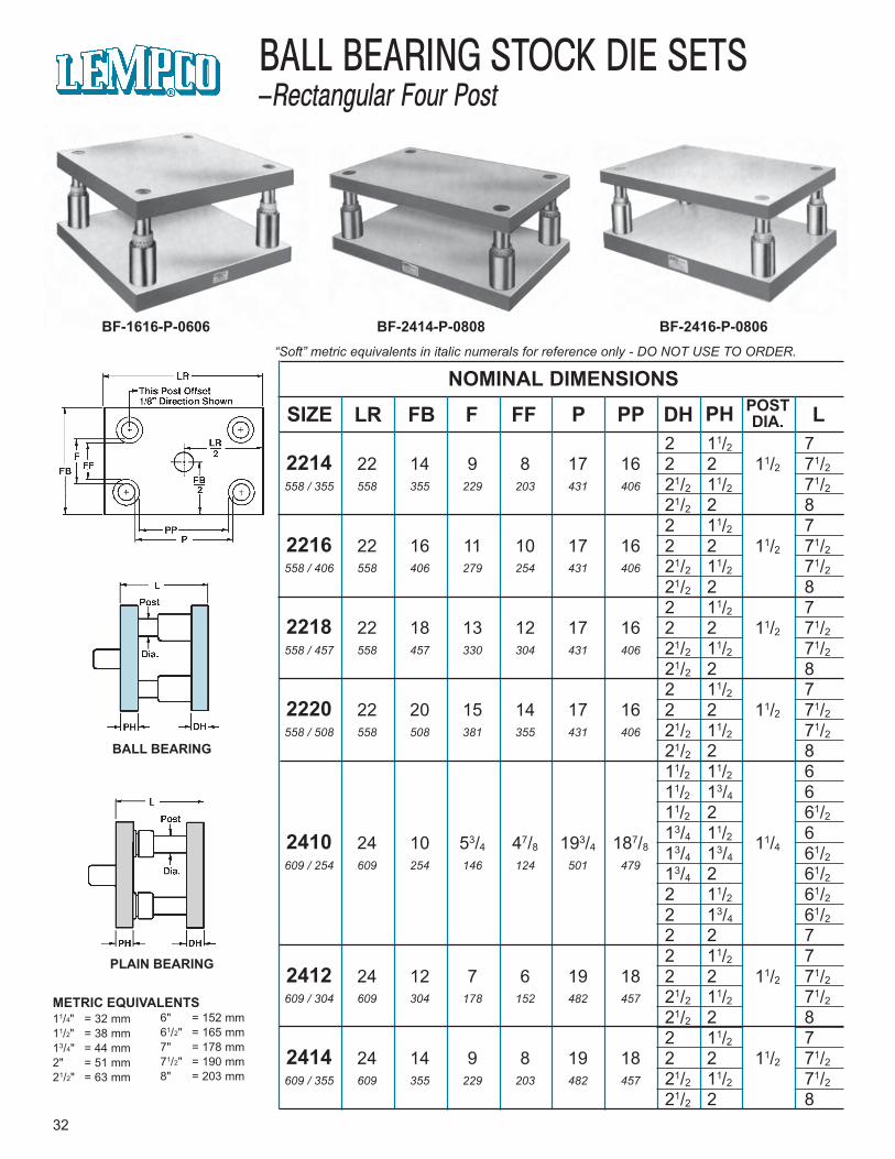
32
BALL BEARING STOCK DIE SETS–Rectangular Four Post
BF-2414-P-0808 BF-2416-P-0806BF-1616-P-0606
BALL BEARING
PLAIN BEARING
NOMINAL DIMENSIONS
SIZE LR F FFFB P PP DH PH POSTDIA. L
METRIC EQUIVALENTS11/4" = 32 mm11/2" = 38 mm13/4" = 44 mm2" = 51 mm21/2" = 63 mm
6" = 152 mm61/2" = 165 mm7" = 178 mm71/2" = 190 mm8" = 203 mm
2 11/2 72214 22 14 9 8 17 16 2 2 11/2 71/2558 / 355 558 355 229 203 431 406 21/2 11/2 71/2
21/2 2 82 11/2 7
2216 22 16 11 10 17 16 2 2 11/2 71/2558 / 406 558 406 279 254 431 406 21/2 11/2 71/2
21/2 2 82 11/2 7
2218 22 18 13 12 17 16 2 2 11/2 71/2558 / 457 558 457 330 304 431 406 21/2 11/2 71/2
21/2 2 82 11/2 7
2220 22 20 15 14 17 16 2 2 11/2 71/2558 / 508 558 508 381 355 431 406 21/2 11/2 71/2
21/2 2 811/2 11/2 611/2 13/4 611/2 2 61/213/4 11/2 62410 24 10 53/4 47/8 193/4 187/8 11/413/4 13/4 61/2
609 / 254 609 254 146 124 501 479 13/4 2 61/22 11/2 61/22 13/4 61/22 2 72 11/2 7
2412 24 12 7 6 19 18 2 2 11/2 71/2609 / 304 609 304 178 152 482 457 21/2 11/2 71/2
21/2 2 82 11/2 7
2414 24 14 9 8 19 18 2 2 11/2 71/2609 / 355 609 355 229 203 482 457 21/2 11/2 71/2
21/2 2 8
HOW TO ORDER . . .
1. Select either Ball Bearing or PlainBearing in the required size, gradeand thickness combination. Showcatalog number of die set selected onyour order.
2. Specify quantity.
3. Specify type of bushing.
4. Specify length “L”. For Ball Bearingsets this is Minimum Shut Heightdimension. For Plain Bearing sets thisis dimension from bottom of die holderto top of guide post.
5. These die sets are stocked “no shank”only. If “Lempcoshank” is desired givecatalog number of kit. Machining ofpunch holder for “Lempcoshank” isavailable on special factory order onlyat an extra cost.
6. Specify thickness combinations otherthan shown. Special or exactthicknesses available at extra cost.
7. Tell us how to ship. Otherwise we willship “best way” in our judgment.
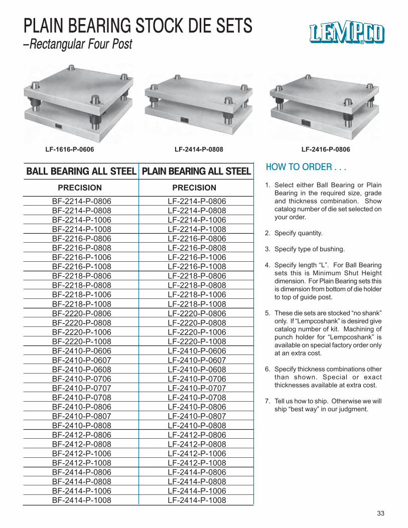
33
PLAIN BEARING STOCK DIE SETS–Rectangular Four Post
LF-1616-P-0606 LF-2414-P-0808 LF-2416-P-0806
PRECISION PRECISION
PLAIN BEARING ALL STEELBALL BEARING ALL STEEL
BF-2214-P-0806 LF-2214-P-0806BF-2214-P-0808 LF-2214-P-0808BF-2214-P-1006 LF-2214-P-1006BF-2214-P-1008 LF-2214-P-1008BF-2216-P-0806 LF-2216-P-0806BF-2216-P-0808 LF-2216-P-0808BF-2216-P-1006 LF-2216-P-1006BF-2216-P-1008 LF-2216-P-1008BF-2218-P-0806 LF-2218-P-0806BF-2218-P-0808 LF-2218-P-0808BF-2218-P-1006 LF-2218-P-1006BF-2218-P-1008 LF-2218-P-1008BF-2220-P-0806 LF-2220-P-0806BF-2220-P-0808 LF-2220-P-0808BF-2220-P-1006 LF-2220-P-1006BF-2220-P-1008 LF-2220-P-1008BF-2410-P-0606 LF-2410-P-0606BF-2410-P-0607 LF-2410-P-0607BF-2410-P-0608 LF-2410-P-0608BF-2410-P-0706 LF-2410-P-0706BF-2410-P-0707 LF-2410-P-0707BF-2410-P-0708 LF-2410-P-0708BF-2410-P-0806 LF-2410-P-0806BF-2410-P-0807 LF-2410-P-0807BF-2410-P-0808 LF-2410-P-0808BF-2412-P-0806 LF-2412-P-0806BF-2412-P-0808 LF-2412-P-0808BF-2412-P-1006 LF-2412-P-1006BF-2412-P-1008 LF-2412-P-1008BF-2414-P-0806 LF-2414-P-0806BF-2414-P-0808 LF-2414-P-0808BF-2414-P-1006 LF-2414-P-1006BF-2414-P-1008 LF-2414-P-1008
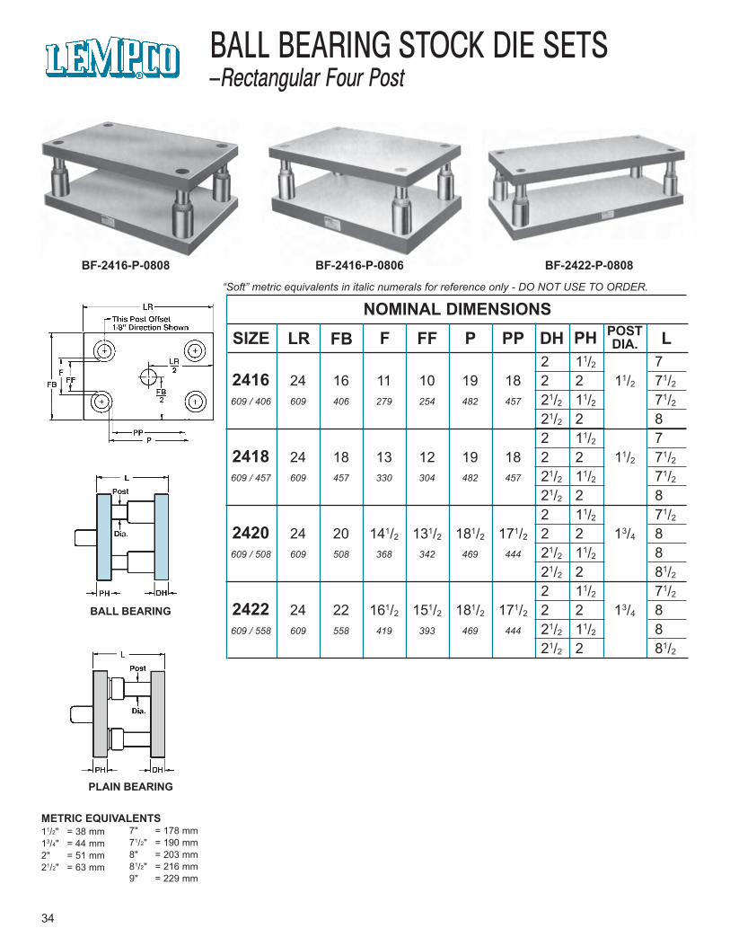
“Soft” metric equivalents in italic numerals for reference only - DO NOT USE TO ORDER.
34
BALL BEARING STOCK DIE SETS–Rectangular Four Post
BF-2416-P-0808 BF-2416-P-0806 BF-2422-P-0808
BALL BEARING
PLAIN BEARING
NOMINAL DIMENSIONS
SIZE LR F FFFB P PP DH PH POSTDIA. L
METRIC EQUIVALENTS11/2" = 38 mm13/4" = 44 mm2" = 51 mm21/2" = 63 mm
7" = 178 mm71/2" = 190 mm8" = 203 mm81/2" = 216 mm9" = 229 mm
2 11/2 72416 24 16 11 10 19 18 2 2 11/2 71/2609 / 406 609 406 279 254 482 457 21/2 11/2 71/2
21/2 2 82 11/2 7
2418 24 18 13 12 19 18 2 2 11/2 71/2609 / 457 609 457 330 304 482 457 21/2 11/2 71/2
21/2 2 82 11/2 71/2
2420 24 20 141/2 131/2 181/2 171/2 2 2 13/4 8609 / 508 609 508 368 342 469 444 21/2 11/2 8
21/2 2 81/22 11/2 71/2
2422 24 22 161/2 151/2 181/2 171/2 2 2 13/4 8609 / 558 609 558 419 393 469 444 21/2 11/2 8
21/2 2 81/2
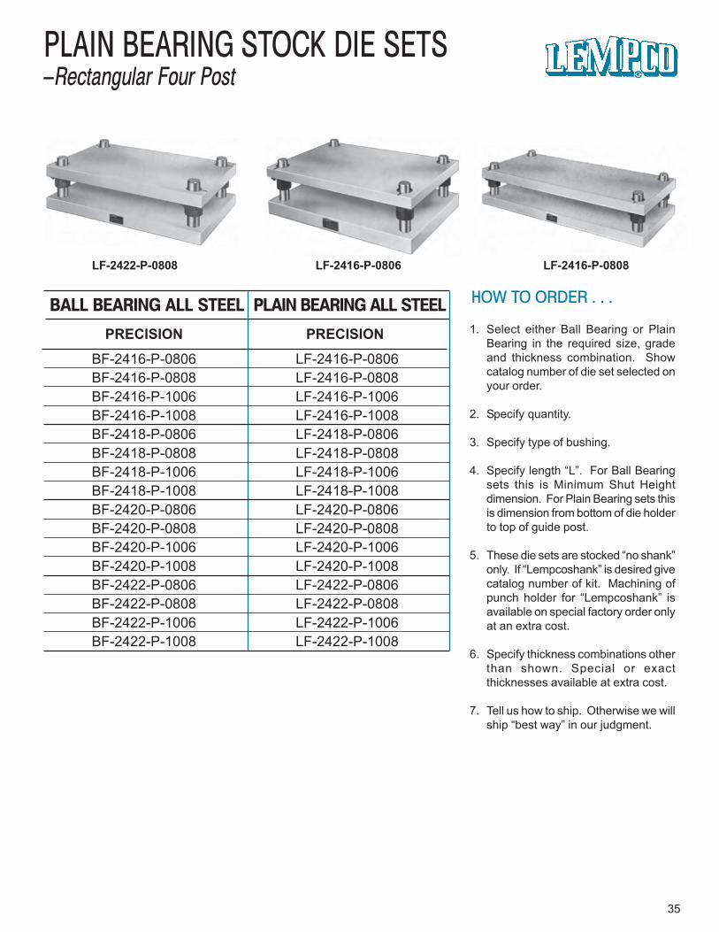
HOW TO ORDER . . .
1. Select either Ball Bearing or PlainBearing in the required size, gradeand thickness combination. Showcatalog number of die set selected onyour order.
2. Specify quantity.
3. Specify type of bushing.
4. Specify length “L”. For Ball Bearingsets this is Minimum Shut Heightdimension. For Plain Bearing sets thisis dimension from bottom of die holderto top of guide post.
5. These die sets are stocked “no shank”only. If “Lempcoshank” is desired givecatalog number of kit. Machining ofpunch holder for “Lempcoshank” isavailable on special factory order onlyat an extra cost.
6. Specify thickness combinations otherthan shown. Special or exactthicknesses available at extra cost.
7. Tell us how to ship. Otherwise we willship “best way” in our judgment.
35
PLAIN BEARING STOCK DIE SETS–Rectangular Four Post
LF-2416-P-0808LF-2422-P-0808 LF-2416-P-0806
PRECISION PRECISION
PLAIN BEARING ALL STEELBALL BEARING ALL STEEL
BF-2416-P-0806 LF-2416-P-0806BF-2416-P-0808 LF-2416-P-0808BF-2416-P-1006 LF-2416-P-1006BF-2416-P-1008 LF-2416-P-1008BF-2418-P-0806 LF-2418-P-0806BF-2418-P-0808 LF-2418-P-0808BF-2418-P-1006 LF-2418-P-1006BF-2418-P-1008 LF-2418-P-1008BF-2420-P-0806 LF-2420-P-0806BF-2420-P-0808 LF-2420-P-0808BF-2420-P-1006 LF-2420-P-1006BF-2420-P-1008 LF-2420-P-1008BF-2422-P-0806 LF-2422-P-0806BF-2422-P-0808 LF-2422-P-0808BF-2422-P-1006 LF-2422-P-1006BF-2422-P-1008 LF-2422-P-1008

36
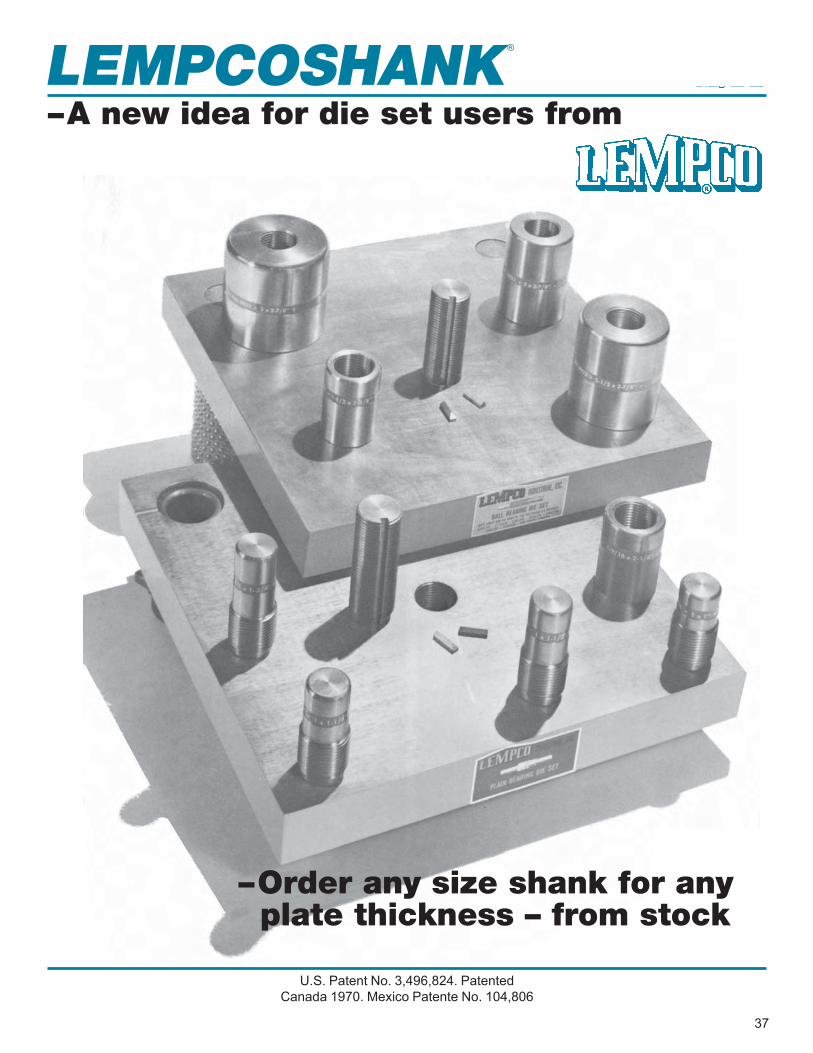
LEMPCOSHANK
37
®
–Order any size shank for any plate thickness – from stock
U.S. Patent No. 3,496,824. PatentedCanada 1970. Mexico Patente No. 104,806
–A new idea for die set users from
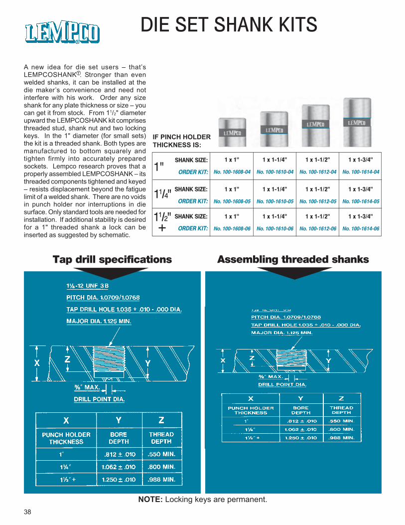
DIE SET SHANK KITS
38
IF PINCH HOLDERTHICKNESS IS:
1"
11/4"
11/2" +
SHANK SIZE:
ORDER KIT:
SHANK SIZE:
ORDER KIT:
SHANK SIZE:
ORDER KIT:
1 x 1" 1 x 1-1/4" 1 x 1-1/2" 1 x 1-3/4"
No. 100-1608-04 No. 100-1610-04 No. 100-1612-04 No. 100-1614-04
1 x 1" 1 x 1-1/4" 1 x 1-1/2" 1 x 1-3/4"
No. 100-1608-05 No. 100-1610-05 No. 100-1612-05 No. 100-1614-05
1 x 1" 1 x 1-1/4" 1 x 1-1/2" 1 x 1-3/4"
No. 100-1608-06 No. 100-1610-06 No. 100-1612-06 No. 100-1614-06
Tap drill specifications Assembling threaded shanks
A new idea for die set users – that’sLEMPCOSHANK T. Stronger than evenwelded shanks, it can be installed at thedie maker’s convenience and need notinterfere with his work. Order any sizeshank for any plate thickness or size – youcan get it from stock. From 11/2" diameterupward the LEMPCOSHANK kit comprisesthreaded stud, shank nut and two lockingkeys. In the 1" diameter (for small sets)the kit is a threaded shank. Both types aremanufactured to bottom squarely andtighten firmly into accurately preparedsockets. Lempco research proves that aproperly assembled LEMPCOSHANK – itsthreaded components tightened and keyed– resists displacement beyond the fatiguelimit of a welded shank. There are no voidsin punch holder nor interruptions in diesurface. Only standard tools are needed forinstallation. If additional stability is desiredfor a 1" threaded shank a lock can beinserted as suggested by schematic.
NOTE: Locking keys are permanent.
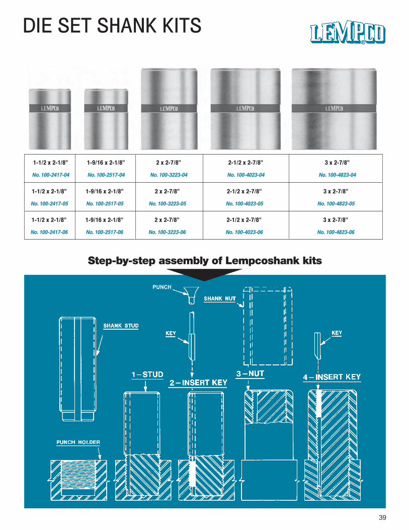
DIE SET SHANK KITS
39
1-1/2 x 2-1/8" 1-9/16 x 2-1/8" 2 x 2-7/8" 2-1/2 x 2-7/8" 3 x 2-7/8"
No. 100-2417-04 No. 100-2517-04 No. 100-3223-04 No. 100-4023-04 No. 100-4823-04
Step-by-step assembly of Lempcoshank kits
PUNCH
1-1/2 x 2-1/8" 1-9/16 x 2-1/8" 2 x 2-7/8" 2-1/2 x 2-7/8" 3 x 2-7/8"
No. 100-2417-05 No. 100-2517-05 No. 100-3223-05 No. 100-4023-05 No. 100-4823-05
1-1/2 x 2-1/8" 1-9/16 x 2-1/8" 2 x 2-7/8" 2-1/2 x 2-7/8" 3 x 2-7/8"
No. 100-2417-06 No. 100-2517-06 No. 100-3223-06 No. 100-4023-06 No. 100-4823-06

WHY LEMPCOSHANK OUTPERFORMS ALL OTHERS
The pre-stressed rigidity which enablesLempcoshank assemblies to outperformeven welded shanks starts withbottoming of the stud in its punch holdersocket. Lowermost threads of bothmembers are stressed by bottoming, asshown at left, without any material effecton the flat, ground working surface ofpunch holder.
40
Assembling the shank nut to stud causesthe nut to bottom against the machinedtop surface of punch holder, creating astress pattern (illustrated at right) in thenut and adjacent portions of shank stud,and in the punch holder itself.
These assembly steps create stresseswhich are not only additive but alsocumulative (illustrated at left). Allmembers are pre-stressed, the criticalportions being fully pre-conditioned. Thelocking keys (not shown) function in therigidly stressed areas, providingadditional stability for entire assembly.
T
QUALITY • DEPENDABILITY • SERVICE • SINCE 1918
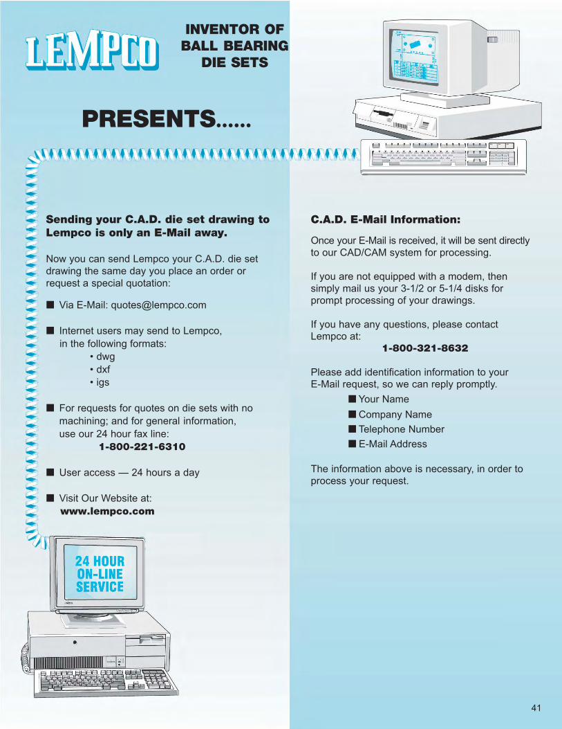
Sending your C.A.D. die set drawing toLempco is only an E-Mail away.
Now you can send Lempco your C.A.D. die setdrawing the same day you place an order orrequest a special quotation:
■ Via E-Mail: [email protected]
■ Internet users may send to Lempco, in the following formats: • dwg • dxf • igs
■ For requests for quotes on die sets with nomachining; and for general information,use our 24 hour fax line: 1-800-221-6310
■ User access — 24 hours a day
■ Visit Our Website at: www.lempco.com
C.A.D. E-Mail Information:
Once your E-Mail is received, it will be sent directlyto our CAD/CAM system for processing.
If you are not equipped with a modem, thensimply mail us your 3-1/2 or 5-1/4 disks forprompt processing of your drawings.
If you have any questions, please contactLempco at:
1-800-321-8632
Please add identification information to yourE-Mail request, so we can reply promptly.
■ Your Name■ Company Name■ Telephone Number■ E-Mail Address
The information above is necessary, in order toprocess your request.
INVENTOR OFBALL BEARING
DIE SETS
PRESENTS......
41

42
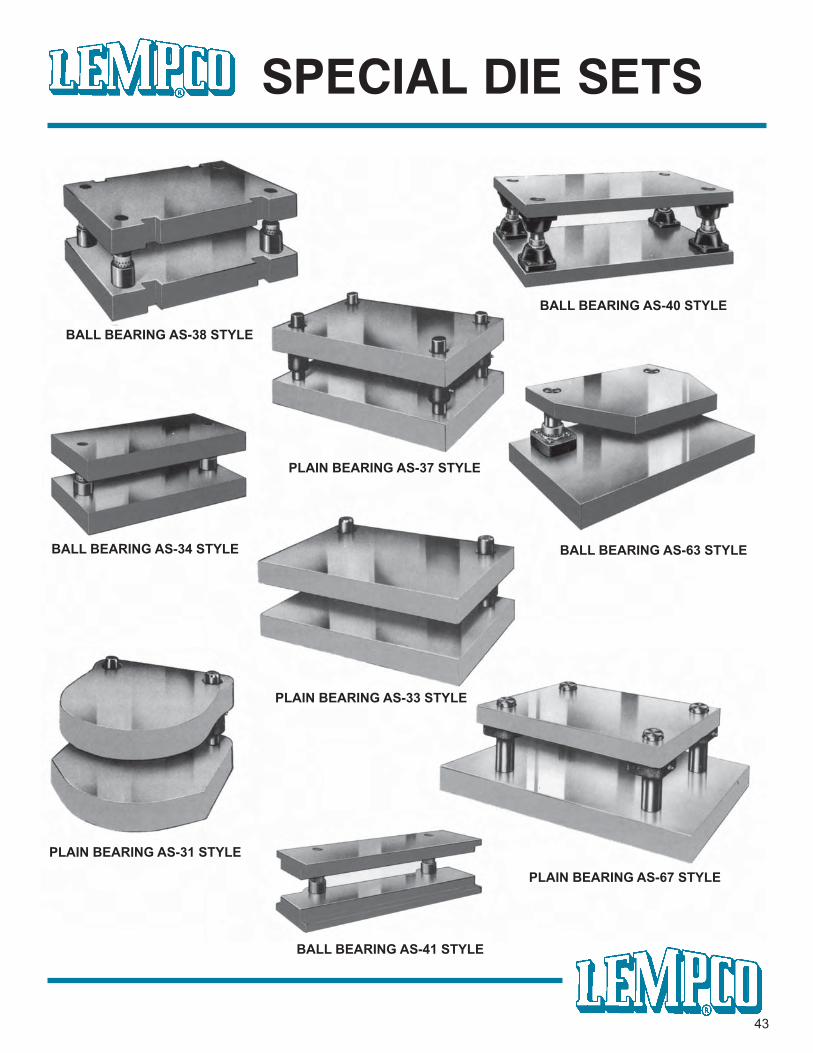
SPECIAL DIE SETS
43
BALL BEARING AS-38 STYLE
BALL BEARING AS-40 STYLE
BALL BEARING AS-34 STYLE BALL BEARING AS-63 STYLE
BALL BEARING AS-41 STYLE
PLAIN BEARING AS-37 STYLE
PLAIN BEARING AS-33 STYLE
PLAIN BEARING AS-31 STYLE
PLAIN BEARING AS-67 STYLE
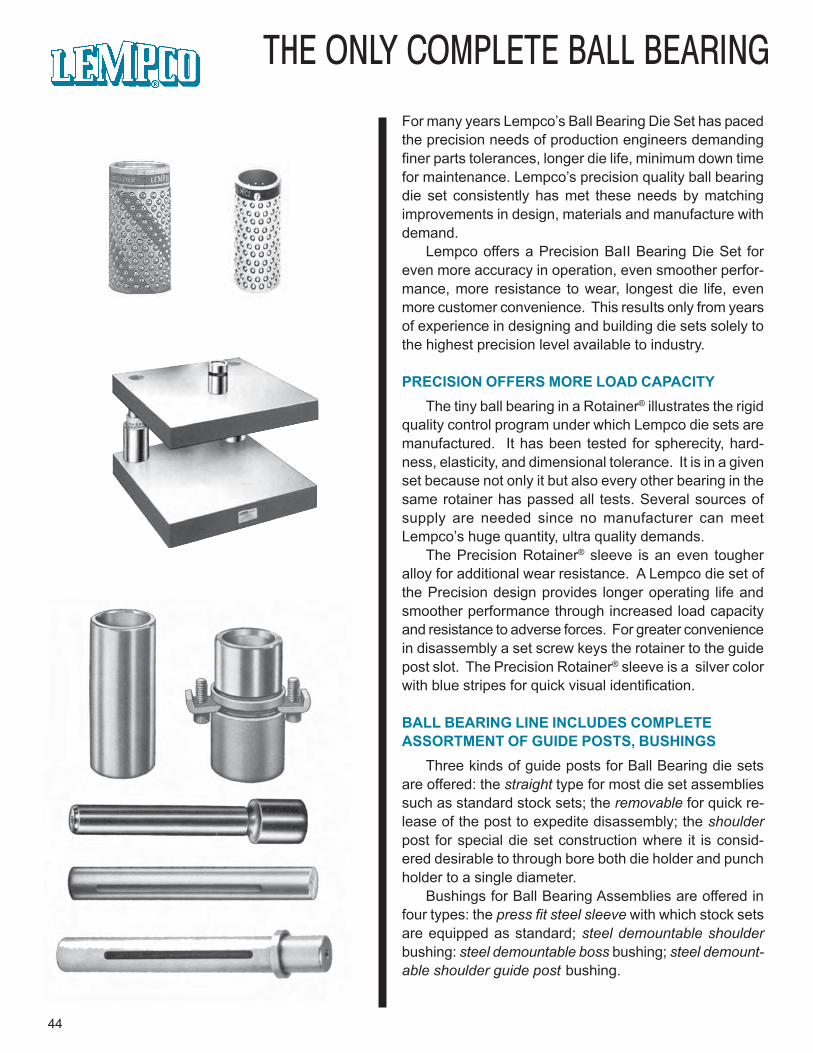
THE ONLY COMPLETE BALL BEARING
For many years Lempco’s Ball Bearing Die Set has pacedthe precision needs of production engineers demandingfiner parts tolerances, longer die life, minimum down timefor maintenance. Lempco’s precision quality ball bearingdie set consistently has met these needs by matchingimprovements in design, materials and manufacture withdemand.
Lempco offers a Precision BaII Bearing Die Set foreven more accuracy in operation, even smoother perfor-mance, more resistance to wear, longest die life, evenmore customer convenience. This resuIts only from yearsof experience in designing and building die sets solely tothe highest precision level available to industry.
PRECISION OFFERS MORE LOAD CAPACITYThe tiny ball bearing in a Rotainer® illustrates the rigid
quality control program under which Lempco die sets aremanufactured. It has been tested for spherecity, hard-ness, elasticity, and dimensional tolerance. It is in a givenset because not only it but also every other bearing in thesame rotainer has passed all tests. Several sources ofsupply are needed since no manufacturer can meetLempco’s huge quantity, ultra quality demands.
The Precision Rotainer® sleeve is an even tougheralloy for additional wear resistance. A Lempco die set ofthe Precision design provides longer operating life andsmoother performance through increased load capacityand resistance to adverse forces. For greater conveniencein disassembly a set screw keys the rotainer to the guidepost slot. The Precision Rotainer® sleeve is a silver colorwith blue stripes for quick visual identification.
BALL BEARING LINE INCLUDES COMPLETEASSORTMENT OF GUIDE POSTS, BUSHINGS
Three kinds of guide posts for Ball Bearing die setsare offered: the straight type for most die set assembliessuch as standard stock sets; the removable for quick re-lease of the post to expedite disassembly; the shoulderpost for special die set construction where it is consid-ered desirable to through bore both die holder and punchholder to a single diameter.
Bushings for Ball Bearing Assemblies are offered infour types: the press fit steel sleeve with which stock setsare equipped as standard; steel demountable shoulderbushing: steel demountable boss bushing; steel demount-able shoulder guide post bushing.
44
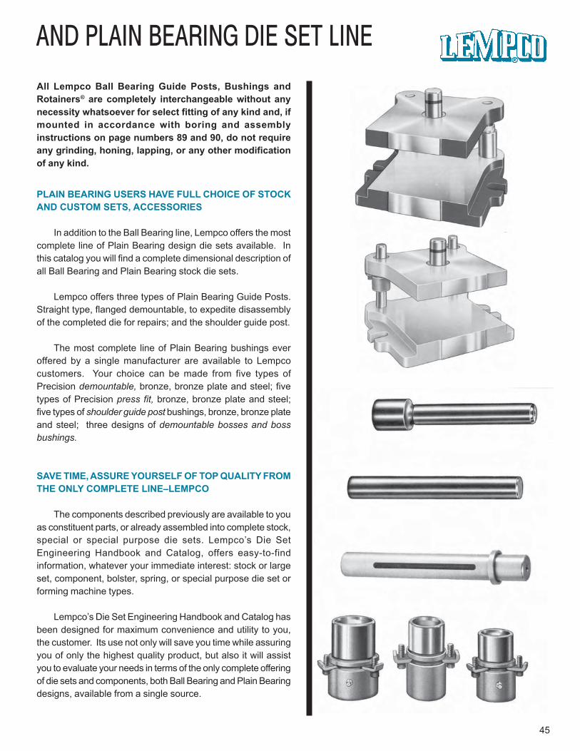
AND PLAIN BEARING DIE SET LINE
45
All Lempco Ball Bearing Guide Posts, Bushings andRotainers® are completely interchangeable without anynecessity whatsoever for select fitting of any kind and, ifmounted in accordance with boring and assemblyinstructions on page numbers 89 and 90, do not requireany grinding, honing, lapping, or any other modificationof any kind.
PLAIN BEARING USERS HAVE FULL CHOICE OF STOCKAND CUSTOM SETS, ACCESSORIES
In addition to the Ball Bearing line, Lempco offers the mostcomplete line of Plain Bearing design die sets available. Inthis catalog you will find a complete dimensional description ofall Ball Bearing and Plain Bearing stock die sets.
Lempco offers three types of Plain Bearing Guide Posts.Straight type, flanged demountable, to expedite disassemblyof the completed die for repairs; and the shoulder guide post.
The most complete line of Plain Bearing bushings everoffered by a single manufacturer are available to Lempcocustomers. Your choice can be made from five types ofPrecision demountable, bronze, bronze plate and steel; fivetypes of Precision press fit, bronze, bronze plate and steel;five types of shoulder guide post bushings, bronze, bronze plateand steel; three designs of demountable bosses and bossbushings.
SAVE TIME, ASSURE YOURSELF OF TOP QUALITY FROMTHE ONLY COMPLETE LINE–LEMPCO
The components described previously are available to youas constituent parts, or already assembled into complete stock,special or special purpose die sets. Lempco’s Die SetEngineering Handbook and Catalog, offers easy-to-findinformation, whatever your immediate interest: stock or largeset, component, bolster, spring, or special purpose die set orforming machine types.
Lempco’s Die Set Engineering Handbook and Catalog hasbeen designed for maximum convenience and utility to you,the customer. Its use not only will save you time while assuringyou of only the highest quality product, but also it will assistyou to evaluate your needs in terms of the only complete offeringof die sets and components, both Ball Bearing and Plain Bearingdesigns, available from a single source.
46
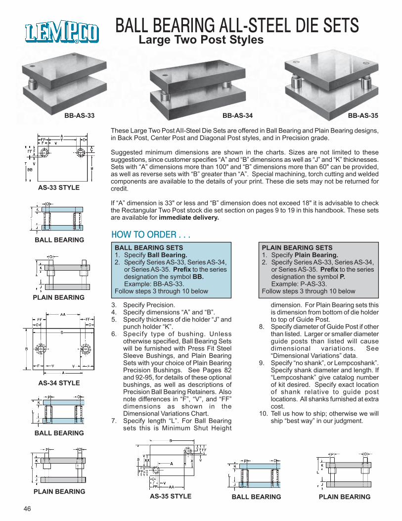
BALL BEARING ALL-STEEL DIE SETSLarge Two Post Styles
BB-AS-33 BB-AS-34 BB-AS-35
AS-33 STYLE
BALL BEARING
PLAIN BEARING
AS-34 STYLE
BALL BEARING
PLAIN BEARINGAS-35 STYLE BALL BEARING PLAIN BEARING
These Large Two Post AII-Steel Die Sets are offered in Ball Bearing and Plain Bearing designs,in Back Post, Center Post and Diagonal Post styles, and in Precision grade.
Suggested minimum dimensions are shown in the charts. Sizes are not limited to thesesuggestions, since customer specifies “A” and “B” dimensions as well as “J” and “K” thicknesses.Sets with “A” dimensions more than 100" and “B” dimensions more than 60" can be provided,as well as reverse sets with “B” greater than “A”. Special machining, torch cutting and weldedcomponents are available to the details of your print. These die sets may not be returned forcredit.
If “A” dimension is 33" or less and “B” dimension does not exceed 18" it is advisable to checkthe Rectangular Two Post stock die set section on pages 9 to 19 in this handbook. These setsare available for immediate delivery.
HOW TO ORDER . . .BALL BEARING SETS1. Specify Ball Bearing.2. Specify Series AS-33, Series AS-34,
or Series AS-35. Prefix to the seriesdesignation the symbol BB.Example: BB-AS-33.
Follow steps 3 through 10 below
PLAIN BEARING SETS1. Specify Plain Bearing.2. Specify Series AS-33, Series AS-34,
or Series AS-35. Prefix to the seriesdesignation the symbol P.Example: P-AS-33.
Follow steps 3 through 10 below
3. Specify Precision.4. Specify dimensions “A” and “B”.5. Specify thickness of die holder “J” and
punch holder “K”.6. Specify type of bushing. Unless
otherwise specified, Ball Bearing Setswill be furnished with Press Fit SteelSleeve Bushings, and Plain BearingSets with your choice of Plain BearingPrecision Bushings. See Pages 82and 92-95, for details of these optionalbushings, as well as descriptions ofPrecision Ball Bearing Retainers. Alsonote differences in “F”, “V”, and “FF”dimensions as shown in theDimensional Variations Chart.
7. Specify length “L”. For Ball Bearingsets this is Minimum Shut Height
dimension. For Plain Bearing sets thisis dimension from bottom of die holderto top of Guide Post.
8. Specify diameter of Guide Post if otherthan listed. Larger or smaller diameterguide posts than listed will causedimensional variations. See“Dimensional Variations” data.
9. Specify “no shank”, or Lempcoshank”.Specify shank diameter and length. If“Lempcoshank” give catalog numberof kit desired. Specify exact locationof shank relative to guide postlocations. All shanks furnished at extracost.
10. Tell us how to ship; otherwise we willship “best way” in our judgment.
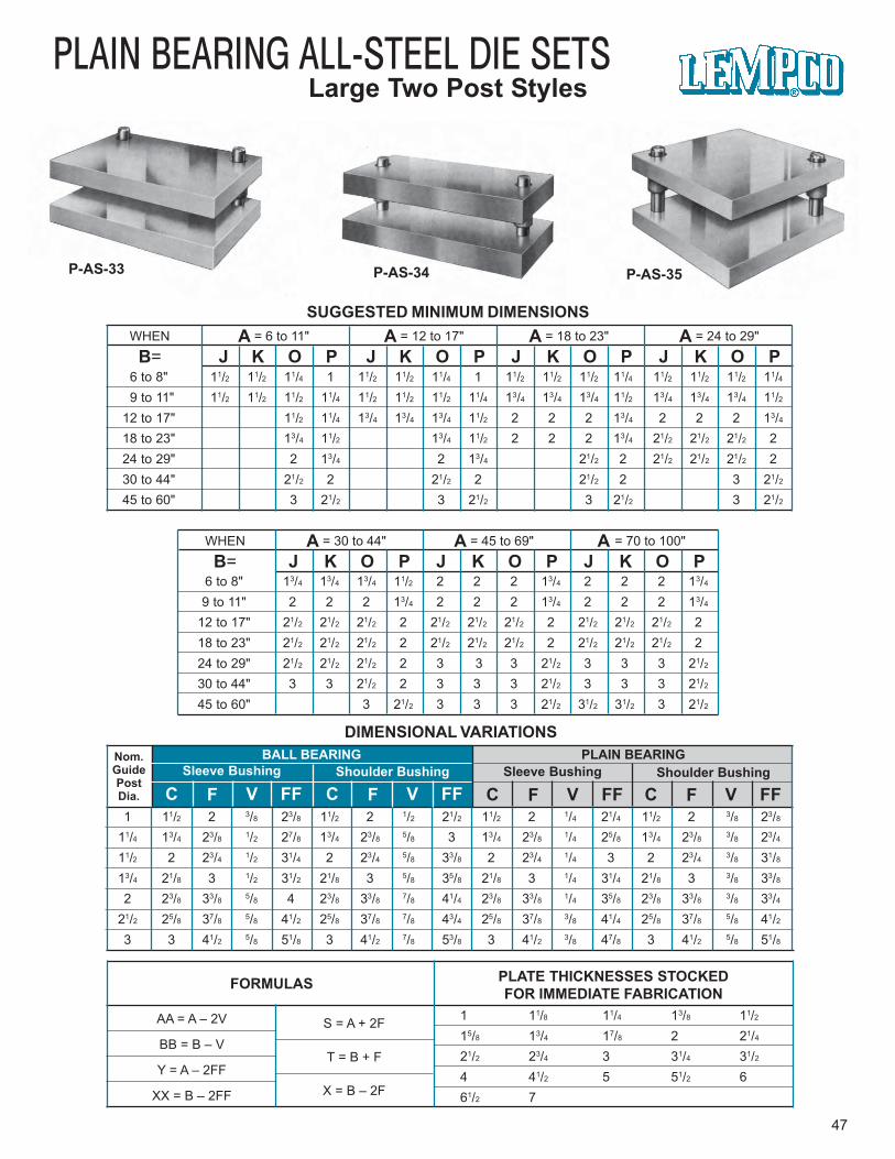
WHEN A = 6 to 11" A = 12 to 17" A = 18 to 23" A = 24 to 29"
B= J K O P J K O P J K O P J K O P
PLAIN BEARING ALL-STEEL DIE SETSLarge Two Post Styles
P-AS-33 P-AS-34 P-AS-35
WHEN A = 30 to 44" A = 45 to 69" A = 70 to 100"
B= J K O P J K O P J K O P6 to 8" 13/4 13/4 13/4 11/2 2 2 2 13/4 2 2 2 13/4
9 to 11" 2 2 2 13/4 2 2 2 13/4 2 2 2 13/4
12 to 17" 21/2 21/2 21/2 2 21/2 21/2 21/2 2 21/2 21/2 21/2 218 to 23" 21/2 21/2 21/2 2 21/2 21/2 21/2 2 21/2 21/2 21/2 224 to 29" 21/2 21/2 21/2 2 3 3 3 21/2 3 3 3 21/2
30 to 44" 3 3 21/2 2 3 3 3 21/2 3 3 3 21/2
45 to 60" 3 21/2 3 3 3 21/2 31/2 31/2 3 21/2
6 to 8" 11/2 11/2 11/4 1 11/2 11/2 11/4 1 11/2 11/2 11/2 11/4 11/2 11/2 11/2 11/49 to 11" 11/2 11/2 11/2 11/4 11/2 11/2 11/2 11/4 13/4 13/4 13/4 11/2 13/4 13/4 13/4 11/2
12 to 17" 11/2 11/4 13/4 13/4 13/4 11/2 2 2 2 13/4 2 2 2 13/4
18 to 23" 13/4 11/2 13/4 11/2 2 2 2 13/4 21/2 21/2 21/2 224 to 29" 2 13/4 2 13/4 21/2 2 21/2 21/2 21/2 230 to 44" 21/2 2 21/2 2 21/2 2 3 21/2
45 to 60" 3 21/2 3 21/2 3 21/2 3 21/2
DIMENSIONAL VARIATIONS
SUGGESTED MINIMUM DIMENSIONS
47
FORMULAS PLATE THICKNESSES STOCKEDFOR IMMEDIATE FABRICATION
AA = A – 2V
BB = B – V
Y = A – 2FF
XX = B – 2FF
S = A + 2F
T = B + F
X = B – 2F
1 11/8 11/4 13/8 11/215/8 13/4 17/8 2 21/4
21/2 23/4 3 31/4 31/2
4 41/2 5 51/2 661/2 7
Nom.GuidePostDia.
BALL BEARINGSleeve Bushing Shoulder Bushing
C F V FF C F V FF
PLAIN BEARINGSleeve Bushing Shoulder Bushing
C F V FF C F V FF1 11/2 2 3/8 23/8 11/2 2 1/2 21/2 11/2 2 1/4 21/4 11/2 2 3/8 23/8
11/4 13/4 23/8 1/2 27/8 13/4 23/8 5/8 3 13/4 23/8 1/4 25/8 13/4 23/8 3/8 23/4
11/2 2 23/4 1/2 31/4 2 23/4 5/8 33/8 2 23/4 1/4 3 2 23/4 3/8 31/8
13/4 21/8 3 1/2 31/2 21/8 3 5/8 35/8 21/8 3 1/4 31/4 21/8 3 3/8 33/8
2 23/8 33/8 5/8 4 23/8 33/8 7/8 41/4 23/8 33/8 1/4 35/8 23/8 33/8 3/8 33/4
21/2 25/8 37/8 5/8 41/2 25/8 37/8 7/8 43/4 25/8 37/8 3/8 41/4 25/8 37/8 5/8 41/2
3 3 41/2 5/8 51/8 3 41/2 7/8 53/8 3 41/2 3/8 47/8 3 41/2 5/8 51/8
48
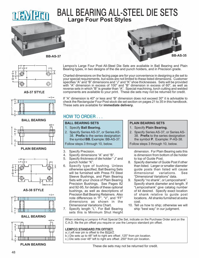
BALL BEARING ALL-STEEL DIE SETSLarge Four Post Styles
BB-AS-37 BB-AS-35
AS-37 STYLE
BALL BEARING
PLAIN BEARING
AS-38 STYLE
BALL BEARING
PLAIN BEARING
Lempco's Large Four Post All-Steel Die Sets are available in Ball Bearing and PlainBearing types, in two designs of the die and punch holders, and in Precision grade.
Charted dimensions on the facing page are for your convenience in designing a die set toyour special requirements, but sizes are not limited to these listed dimensions. Customerspecifies “A” and “B” dimensions and “J” and “K” shoe thicknesses. Sets will be providedwith “A” dimension in excess of 100" and “B” dimension in excess of 60", as well asreverse sets in which “B” is greater than “A”. Special machining, torch cutting and weldedcomponents are available to your print. These die sets may not be returned for credit.
If “A” dimension is 40" or less and “B” dimension does not exceed 30" it is advisable tocheck the Rectangular Four Post stock die set section on pages 21 to 35 in this handbook.These sets are available for immediate delivery.
HOW TO ORDER . . .BALL BEARING SETS1. Specify Ball Bearing.2. Specify Series AS-37, or Series AS-
38. Prefix to the series designationthe symbol BB. Example: BB-AS-37.
Follow steps 3 through 10, below.
PLAIN BEARING SETS1. Specify Plain Bearing.2. Specify Series AS-37, or Series AS-
38. Prefix to the series designationthe symbol P. Example: P-AS-38.
Follow steps 3 through 10, below.
3. Specify Precision.4. Specify dimensions “A” and “B”.5. Specify thickness of die holder “ J” and
punch holder “K”.6. Specify type of bushing. Unless
otherwise specified, Ball Bearing Setswill be furnished with Press Fit SteelSleeve Bushings, and Plain BearingSets with your choice of Plain BearingPrecision Bushings. See Pages 82and 92-95, for details of these optionalbushings, as well as descriptions ofPrecision Ball Bearing Retainers. Alsonote differences in “F”, “V”, and “FF”dimensions as shown in theDimensional Variations Chart.
7. Specify length “L”. For Ball Bearingsets this is Minimum Shut Height
dimension. For Plain Bearing sets thisis dimension from bottom of die holderto top of Guide Post.
8. Specify diameter of Guide Post if otherthan listed. Larger or smaller diameterguide posts than listed will causedimensional variations. See“Dimensional Variations” data.
9. Specify “no shank”, or Lempcoshank”.Specify shank diameter and length. If“Lempcoshank” give catalog numberof kit desired. Specify exact locationof shank relative to guide postlocations. All shanks furnished at extracost.
10. Tell us how to ship; otherwise we willship “best way” in our judgment.
When ordering a Lempco 4-Post Special Die Set, indicate on the Purchase Order and on theC.A.D. file the pin offset you require or use the Lempco standard pin offset.
LEMPCO STANDARD PIN OFFSET:a.) Left rear pin is offset to the RIGHT.b.) Die sets up to 48" left to right are offset .125" from pin location.c.) Die sets over 48" left to right are offset .250" from pin location.
These die sets may not be returned for credit.
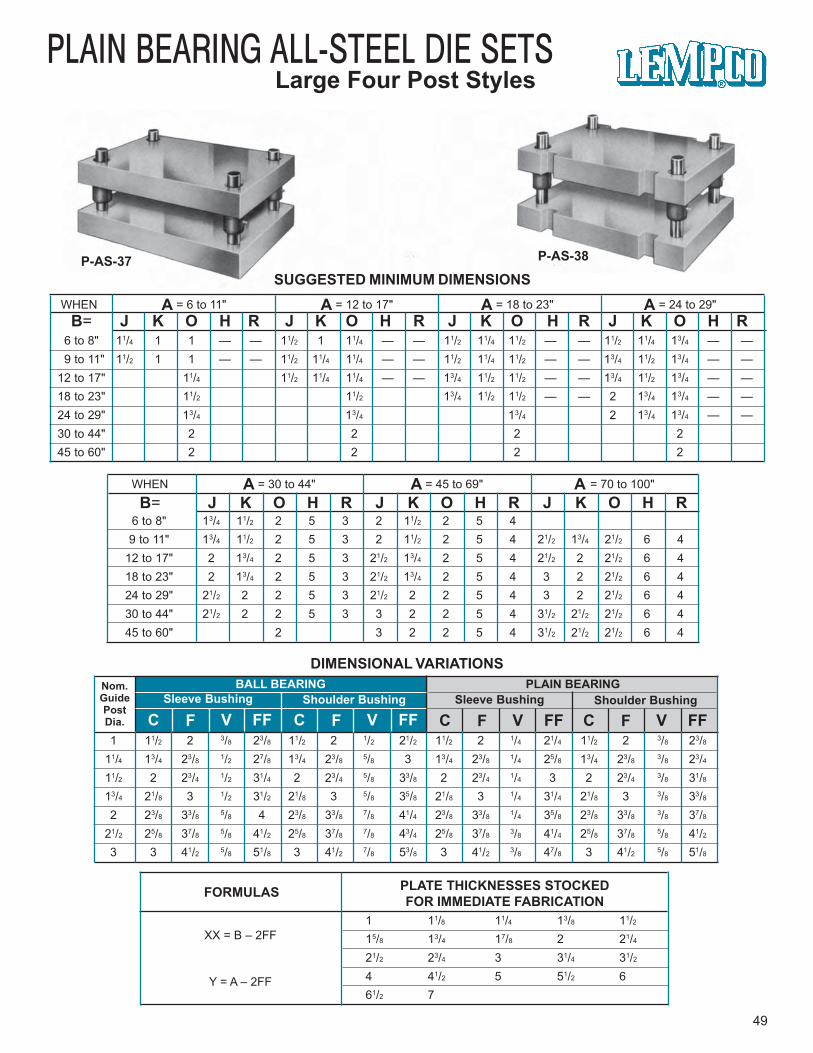
6 to 8" 13/4 11/2 2 5 3 2 11/2 2 5 49 to 11" 13/4 11/2 2 5 3 2 11/2 2 5 4 21/2 13/4 21/2 6 4
12 to 17" 2 13/4 2 5 3 21/2 13/4 2 5 4 21/2 2 21/2 6 418 to 23" 2 13/4 2 5 3 21/2 13/4 2 5 4 3 2 21/2 6 424 to 29" 21/2 2 2 5 3 21/2 2 2 5 4 3 2 21/2 6 430 to 44" 21/2 2 2 5 3 3 2 2 5 4 31/2 21/2 21/2 6 445 to 60" 2 3 2 2 5 4 31/2 21/2 21/2 6 4
WHEN A = 30 to 44" A = 45 to 69" A = 70 to 100"
B= J K O H R J K O H R J K O H R
B= J K O H R J K O H R J K O H R J K O H RWHEN A = 6 to 11" A = 12 to 17" A = 18 to 23" A = 24 to 29"
PLAIN BEARING ALL-STEEL DIE SETSLarge Four Post Styles
P-AS-37 P-AS-38
DIMENSIONAL VARIATIONS
SUGGESTED MINIMUM DIMENSIONS
49
FORMULAS PLATE THICKNESSES STOCKEDFOR IMMEDIATE FABRICATION
XX = B – 2FF
Y = A – 2FF
1 11/8 11/4 13/8 11/215/8 13/4 17/8 2 21/4
21/2 23/4 3 31/4 31/2
4 41/2 5 51/2 661/2 7
Nom.GuidePostDia.
BALL BEARINGSleeve Bushing Shoulder Bushing
C F V FF C F V FF
PLAIN BEARINGSleeve Bushing Shoulder Bushing
C F V FF C F V FF1 11/2 2 3/8 23/8 11/2 2 1/2 21/2 11/2 2 1/4 21/4 11/2 2 3/8 23/8
11/4 13/4 23/8 1/2 27/8 13/4 23/8 5/8 3 13/4 23/8 1/4 25/8 13/4 23/8 3/8 23/4
11/2 2 23/4 1/2 31/4 2 23/4 5/8 33/8 2 23/4 1/4 3 2 23/4 3/8 31/8
13/4 21/8 3 1/2 31/2 21/8 3 5/8 35/8 21/8 3 1/4 31/4 21/8 3 3/8 33/8
2 23/8 33/8 5/8 4 23/8 33/8 7/8 41/4 23/8 33/8 1/4 35/8 23/8 33/8 3/8 37/8
21/2 25/8 37/8 5/8 41/2 25/8 37/8 7/8 43/4 25/8 37/8 3/8 41/4 25/8 37/8 5/8 41/2
3 3 41/2 5/8 51/8 3 41/2 7/8 53/8 3 41/2 3/8 47/8 3 41/2 5/8 51/8
6 to 8" 11/4 1 1 — — 11/2 1 11/4 — — 11/2 11/4 11/2 — — 11/2 11/4 13/4 — —9 to 11" 11/2 1 1 — — 11/2 11/4 11/4 — — 11/2 11/4 11/2 — — 13/4 11/2 13/4 — —
12 to 17" 11/4 11/2 11/4 11/4 — — 13/4 11/2 11/2 — — 13/4 11/2 13/4 — —18 to 23" 11/2 11/2 13/4 11/2 11/2 — — 2 13/4 13/4 — —24 to 29" 13/4 13/4 13/4 2 13/4 13/4 — —30 to 44" 2 2 2 245 to 60" 2 2 2 2

50
BALL BEARING ALL-STEEL DIE SETSDemountable Boss Styles
BB-AS-39 BB-AS-40
AS-39 STYLE
BALL BEARING
PLAIN BEARING
AS-40 STYLE
BALL BEARING
PLAIN BEARING
Additional flexibility in the design of large special die sets; is offered by Lempco’s All-Steel Demountable Boss construction, and is available in both Ball Bearing and PlainBearing types. These sets are manufactured in Two-Post and Four-Post styles, in Precisiongrade.
Two combinations of bosses are available in both Ball Bearing and Plain Bearing.Combination No. 1 is preferred for heavy duty work where maximum support is required.Combination No. 2 is recommended when the shut height of the press is limited.
Suggested minimum dimensions are provided in the charts, but sets with “A” dimensionexceeding 100" and “B” dimension more than 60" are also available. Reverse sets with“B” greater than “A” may be ordered. The “J” and “K” thicknesses are subject to customerspecifications. Special machining, torch-cutting, and welded components are done todetails of customer’s print or templet. These die sets may not be returned for credit.
GENERAL DIMENSIONS
BALL BEARING
AS-39 AS-40
PLAIN BEARING
AS-39 AS-40
WHEN A = 30 to 44"
B = J K 6 to 8" 13/4 2 9 to 11" 2 2 O = 2 O = 212 to 17" 21/2 21/2 H = 51/2 O = 2 H = 5 O = 218 to 23" 21/2 21/2 P = 21/2 H = 51/2 P = 21/2 H = 524 to 29" 3 3 G = 6 AA = A –2H G = 6 AA = A–2H30 to 44" 3 3 AA = A–(H+G) BB = B–2H AA = A–(H+G) BB = B–2H45 to 60" 3 3
WHEN A = 45 to 69"
B = J K 6 to 8" 2 2 9 to 11" 2 2 O = 2 O = 212 to 17" 21/2 21/2 H = 51/2 O = 2 H = 5 O = 218 to 23" 21/2 21/2 P = 21/2 H = 51/2 P = 21/2 H = 524 to 29" 3 3 G = 6 AA = A –2H G = 6 AA = A–2H30 to 44" 3 3 AA = A–(H+G) BB = B–2H AA = A–(H+G) BB = B–2H45 to 60" 3 3
WHEN A = 70 to 100"
B = J K 6 to 8" 2 2 9 to 11" 2 2 O = 21/2 O = 21/2
12 to 17" 21/2 21/2 H = 6 O = 21/2 H = 6 O = 21/2
18 to 23" 21/2 21/2 P = 3 H = 6 P = 3 H = 624 to 29" 3 3 G = 7 AA = A –2H G = 7 AA = A–2H30 to 44" 3 3 AA = A–(H+G) BB = B–2H AA = A–(H+G) BB = B–2H45 to 60" 31/2 31/2
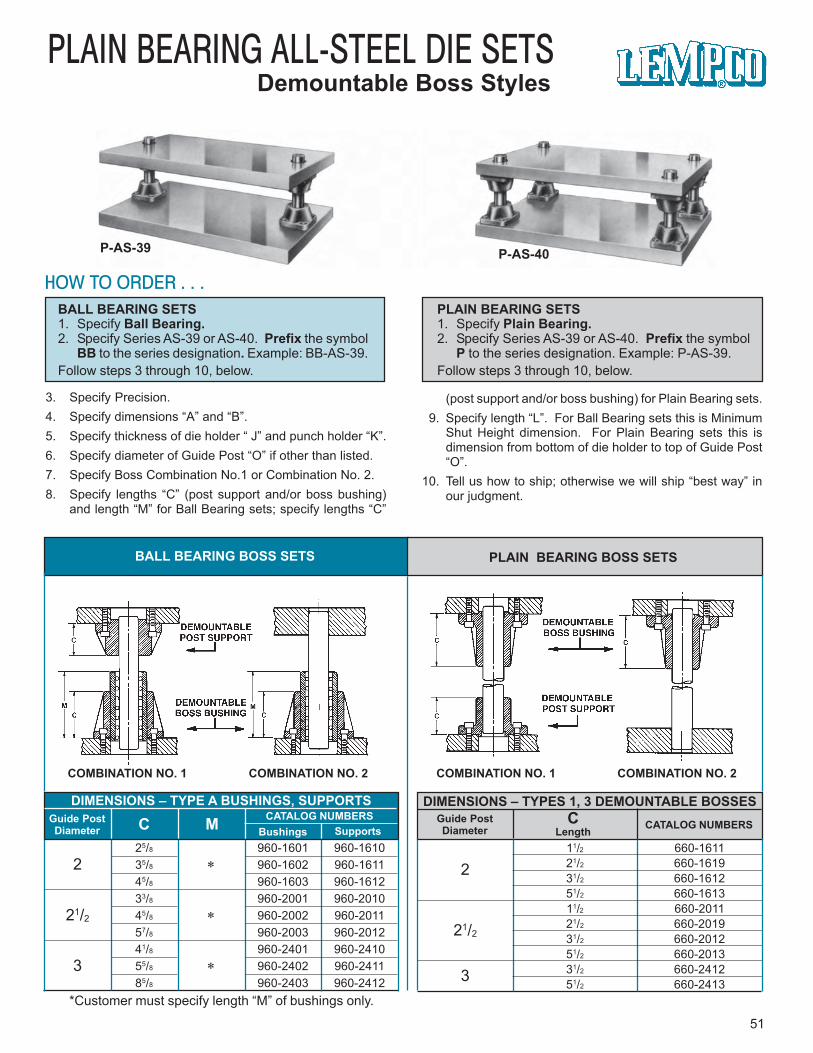
PLAIN BEARING ALL-STEEL DIE SETSDemountable Boss Styles
P-AS-39 P-AS-40
51
HOW TO ORDER . . .BALL BEARING SETS1. Specify Ball Bearing.2. Specify Series AS-39 or AS-40. Prefix the symbol
BB to the series designation. Example: BB-AS-39.Follow steps 3 through 10, below.
PLAIN BEARING SETS1. Specify Plain Bearing.2. Specify Series AS-39 or AS-40. Prefix the symbol
P to the series designation. Example: P-AS-39.Follow steps 3 through 10, below.
3. Specify Precision.4. Specify dimensions “A” and “B”.5. Specify thickness of die holder “ J” and punch holder “K”.6. Specify diameter of Guide Post “O” if other than listed.7. Specify Boss Combination No.1 or Combination No. 2.8. Specify lengths “C” (post support and/or boss bushing)
and length “M” for Ball Bearing sets; specify lengths “C”
(post support and/or boss bushing) for Plain Bearing sets. 9. Specify length “L”. For Ball Bearing sets this is Minimum
Shut Height dimension. For Plain Bearing sets this isdimension from bottom of die holder to top of Guide Post“O”.
10. Tell us how to ship; otherwise we will ship “best way” inour judgment.
BALL BEARING BOSS SETS PLAIN BEARING BOSS SETS
COMBINATION NO. 1 COMBINATION NO. 2 COMBINATION NO. 1 COMBINATION NO. 2
*Customer must specify length “M” of bushings only.
DIMENSIONS – TYPES 1, 3 DEMOUNTABLE BOSSESGuide PostDiameter
CLength CATALOG NUMBERS
DIMENSIONS – TYPE A BUSHINGS, SUPPORTSGuide PostDiameter C M CATALOG NUMBERS
Bushings Supports
2
21/2
3
*
*
*
25/8 960-1601 960-161035/8 960-1602 960-161145/8 960-1603 960-161233/8 960-2001 960-201045/8 960-2002 960-201157/8 960-2003 960-201241/8 960-2401 960-241055/8 960-2402 960-241185/8 960-2403 960-2412
2
21/2
3
11/2 660-161121/2 660-161931/2 660-161251/2 660-161311/2 660-201121/2 660-201931/2 660-201251/2 660-201331/2 660-241251/2 660-2413
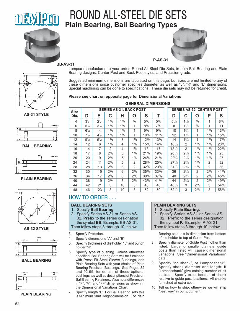
52
ROUND ALL-STEEL DIE SETSPlain Bearing, Ball Bearing Types
BB-AS-31P-AS-31
AS-31 STYLE
BALL BEARING
PLAIN BEARING
AS-32 STYLE
BALL BEARING
PLAIN BEARING
Lempco manufactures to your order, Round All-Steel Die Sets, in both Ball Bearing and PlainBearing designs, Center Post and Back Post styles, and Precision grade.
Suggested minimum dimensions are tabulated on this page, but sizes are not limited to any ofthese dimensions since customer specifies diameter as well as “J”, “K” and “L” dimensions.Special machining can be done to specifications. These die sets may not be returned for credit.
Please see chart on opposite page for Dimensional Variations
HOW TO ORDER . . .BALL BEARING SETS1. Specify Ball Bearing.2. Specify Series AS-31 or Series AS-
32. Prefix to the series designationthe symbol BB. Example: BB-AS-31.
Then follow steps 3 through 10, below.
PLAIN BEARING SETS1. Specify Plain Bearing.2. Specify Series AS-31 or Series AS-
32. Prefix to the series designationthe symbol P. Example: P-AS-31.
Then follow steps 3 through 10, below.
3. Specify Precision.4. Specify dimensions “A” and “B”.5. Specify thickness of die holder “ J” and punch
holder “K”.6. Specify type of bushing. Unless otherwise
specified, Ball Bearing Sets will be furnishedwith Press Fit Steel Sleeve Bushings, andPlain Bearing Sets with your choice of PlainBearing Precision Bushings. See Pages 82and 92-95, for details of these optionalbushings, as well as descriptions of PrecisionBall Bearing Retainers. Also note differencesin “F”, “V”, and “FF” dimensions as shown inthe Dimensional Variations Chart.
7. Specify length “L”. For Ball Bearing sets thisis Minimum Shut Height dimension. For Plain
Bearing sets this is dimension from bottomof die holder to top of Guide Post.
8. Specify diameter of Guide Post if other thanlisted. Larger or smaller diameter guideposts than listed will cause dimensionalvariations. See “Dimensional Variations”data.
9. Specify “no shank”, or Lempcoshank”.Specify shank diameter and length. If“Lempcoshank” give catalog number of kitdesired. Specify exact location of shankrelative to guide post locations. All shanksfurnished at extra cost.
10. Tell us how to ship; otherwise we will ship“best way” in our judgment.
GENERAL DIMENSIONSSERIES AS-31, BACK POST SERIES AS-32, CENTER POSTSize
Dia. D E C H O S T D C O P S 4 31/4 21/4 11/8 11/4 3/4 51/2 53/8 51/2 11/2 3/4 1 81/2
6 51/8 31/4 11/2 11/2 1 81/8 73/4 8 11/2 3/4 1 11 8 61/2 4 11/2 11/2 1 91/2 91/2 10 13/4 1 11/4 131/2
10 73/4 43/4 11/2 13/4 1 103/4 111/4 12 13/4 1 11/4 151/2
12 91/8 51/2 13/4 3 11/4 125/8 131/4 14 13/4 1 11/4 171/2
14 12 6 13/4 4 11/4 151/2 143/4 161/2 2 11/4 11/2 201/2
16 14 7 2 4 11/2 18 17 181/2 2 11/4 11/2 221/2
18 17 8 21/8 5 13/4 211/4 191/8 203/4 21/8 11/2 13/4 2520 20 9 21/8 5 13/4 241/4 211/8 223/4 21/8 11/2 13/4 2724 24 11 23/8 5 2 283/4 253/8 271/2 23/8 13/4 2 3228 28 13 23/8 6 2 323/4 293/8 311/2 23/8 13/4 2 3632 30 15 25/8 6 21/2 351/4 335/8 36 25/8 2 21/2 411/436 34 17 25/8 8 21/2 391/4 375/8 40 25/8 2 21/2 451/4
40 38 19 25/8 8 21/2 431/4 415/8 44 25/8 2 21/2 491/4
44 42 21 3 10 3 48 46 481/2 3 21/2 3 541/2
48 46 23 3 10 3 52 50 521/2 3 21/2 3 581/2
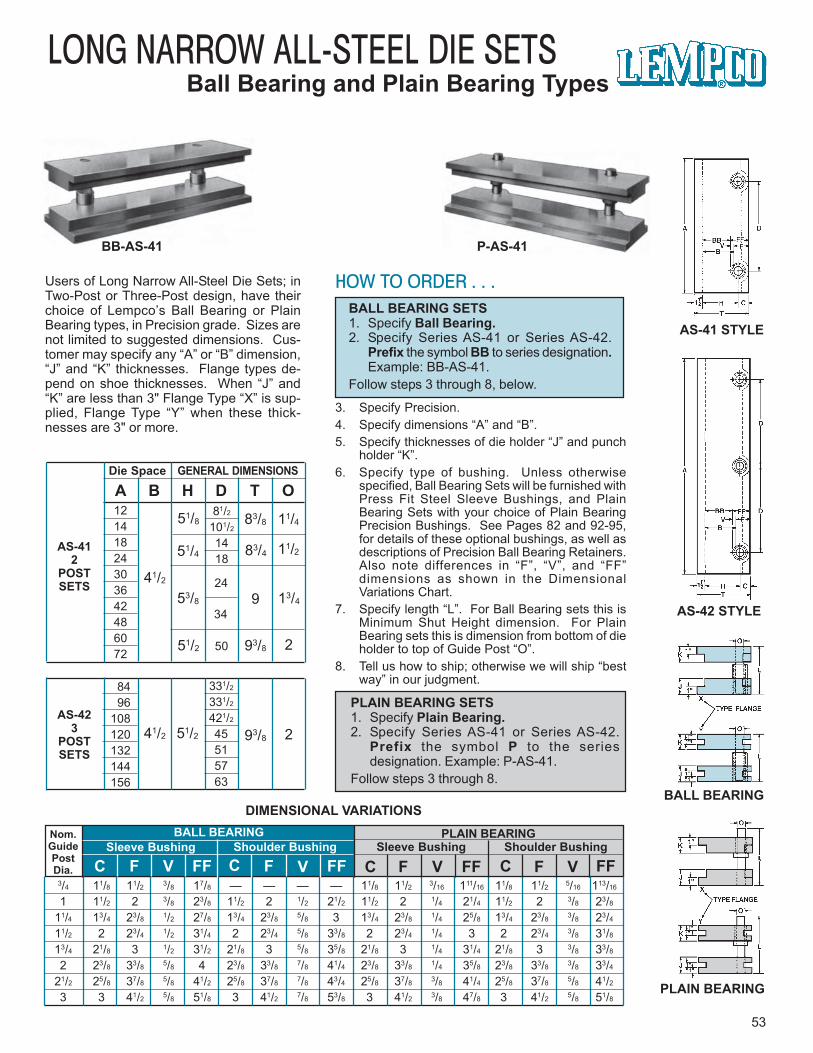
LONG NARROW ALL-STEEL DIE SETSBall Bearing and Plain Bearing Types
BB-AS-41 P-AS-41
53
HOW TO ORDER . . .BALL BEARING SETS1. Specify Ball Bearing.2. Specify Series AS-41 or Series AS-42.
Prefix the symbol BB to series designation.Example: BB-AS-41.
Follow steps 3 through 8, below.
3. Specify Precision.4. Specify dimensions “A” and “B”.5. Specify thicknesses of die holder “J” and punch
holder “K”.6. Specify type of bushing. Unless otherwise
specified, Ball Bearing Sets will be furnished withPress Fit Steel Sleeve Bushings, and PlainBearing Sets with your choice of Plain BearingPrecision Bushings. See Pages 82 and 92-95,for details of these optional bushings, as well asdescriptions of Precision Ball Bearing Retainers.Also note differences in “F”, “V”, and “FF”dimensions as shown in the DimensionalVariations Chart.
7. Specify length “L”. For Ball Bearing sets this isMinimum Shut Height dimension. For PlainBearing sets this is dimension from bottom of dieholder to top of Guide Post “O”.
8. Tell us how to ship; otherwise we will ship “bestway” in our judgment.
PLAIN BEARING SETS1. Specify Plain Bearing.2. Specify Series AS-41 or Series AS-42.
Prefix the symbol P to the seriesdesignation. Example: P-AS-41.
Follow steps 3 through 8.
Users of Long Narrow All-Steel Die Sets; inTwo-Post or Three-Post design, have theirchoice of Lempco’s Ball Bearing or PlainBearing types, in Precision grade. Sizes arenot limited to suggested dimensions. Cus-tomer may specify any “A” or “B” dimension,“J” and “K” thicknesses. Flange types de-pend on shoe thicknesses. When “J” and“K” are less than 3" Flange Type “X” is sup-plied, Flange Type “Y” when these thick-nesses are 3" or more.
AS-412
POSTSETS
AS-423
POSTSETS
Die Space GENERAL DIMENSIONS
A B H D T O
41/2
41/2
51/8
51/4
53/8
51/2
83/8
83/4
9
93/8
11/4
11/2
13/4
2
93/8 251/2
12141824303642486072
81/2
101/2
1418
24
34
50
84 96108120132144156
331/2
331/2
421/2
45515763
C F V FF C F V FF
Nom.GuidePostDia.
BALL BEARINGSleeve Bushing Shoulder Bushing
PLAIN BEARINGSleeve Bushing Shoulder Bushing
C F V FF C F V FF3/4 11/8 11/2 3/8 17/8 — — — — 11/8 11/2 3/16 111/16 11/8 11/2 5/16 113/16
1 11/2 2 3/8 23/8 11/2 2 1/2 21/2 11/2 2 1/4 21/4 11/2 2 3/8 23/8
11/4 13/4 23/8 1/2 27/8 13/4 23/8 5/8 3 13/4 23/8 1/4 25/8 13/4 23/8 3/8 23/4
11/2 2 23/4 1/2 31/4 2 23/4 5/8 33/8 2 23/4 1/4 3 2 23/4 3/8 31/8
13/4 21/8 3 1/2 31/2 21/8 3 5/8 35/8 21/8 3 1/4 31/4 21/8 3 3/8 33/8
2 23/8 33/8 5/8 4 23/8 33/8 7/8 41/4 23/8 33/8 1/4 35/8 23/8 33/8 3/8 33/4
21/2 25/8 37/8 5/8 41/2 25/8 37/8 7/8 43/4 25/8 37/8 3/8 41/4 25/8 37/8 5/8 41/2
3 3 41/2 5/8 51/8 3 41/2 7/8 53/8 3 41/2 3/8 47/8 3 41/2 5/8 51/8
DIMENSIONAL VARIATIONS
AS-41 STYLE
BALL BEARING
PLAIN BEARING
AS-42 STYLE
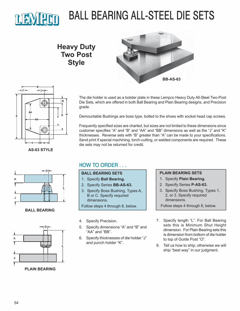
BB-AS-63
54
BALL BEARING ALL-STEEL DIE SETS
Heavy DutyTwo Post
Style
AS-63 STYLE
BALL BEARING
PLAIN BEARING
The die holder is used as a bolster plate in these Lempco Heavy Duty All-Steel Two-PostDie Sets, which are offered in both Ball Bearing and Plain Bearing designs, and Precisiongrade.
Demountable Bushings are boss type, bolted to the shoes with socket head cap screws.
Frequently specified sizes are charted, but sizes are not limited to these dimensions sincecustomer specifies “A” and “B” and “AA” and “BB” dimensions as well as the “J” and “K”thicknesses. Reverse sets with “B” greater than “A” can be made to your specifications.Send print if special machining, torch-cutting, or welded components are required. Thesedie sets may not be returned for credit.
HOW TO ORDER . . .BALL BEARING SETS1. Specify Ball Bearing.2. Specify Series BB-AS-63.3. Specify Boss Bushing, Types A,
B or C. Specify requireddimensions.
Follow steps 4 through 8, below.
PLAIN BEARING SETS1. Specify Plain Bearing.2. Specify Series P-AS-63.3. Specify Boss Bushing, Types 1,
2, or 3. Specify requireddimensions.
Follow steps 4 through 8, below.
4. Specify Precision.5. Specify dimensions “A” and “B” and
“AA” and “BB”.6. Specify thicknesses of die holder “J”
and punch holder “K”.
7. Specify length “L”. For Ball Bearingsets this is Minimum Shut Heightdimension. For Plain Bearing sets thisis dimension from bottom of die holderto top of Guide Post “O”.
8. Tell us how to ship; otherwise we willship “best way” in our judgment.
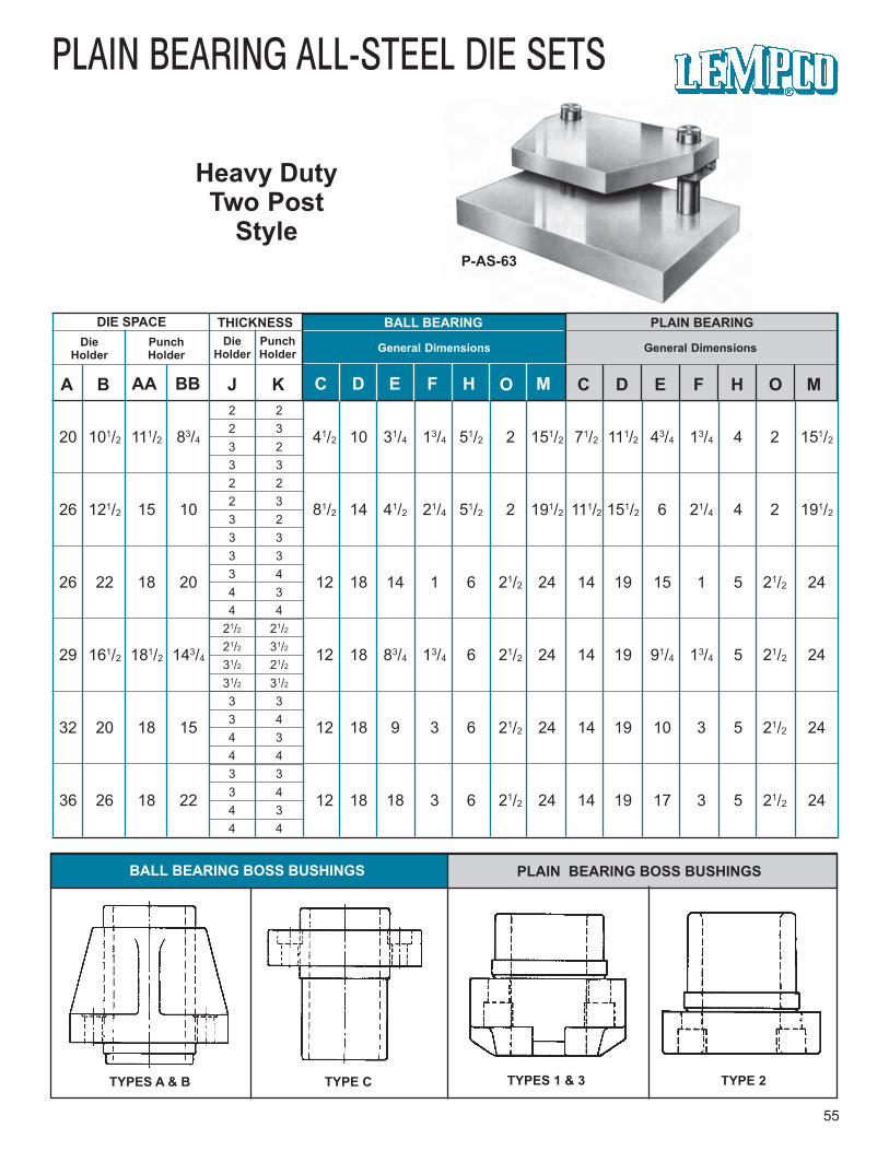
PLAIN BEARING ALL-STEEL DIE SETS
Heavy DutyTwo Post
StyleP-AS-63
55
BALL BEARING BOSS BUSHINGS PLAIN BEARING BOSS BUSHINGS
TYPES A & B TYPE C TYPES 1 & 3 TYPE 2
PLAIN BEARING
General Dimensions
BALL BEARING
General Dimensions
THICKNESSDie
HolderPunchHolder
DieHolder
PunchHolder
DIE SPACE
A B AA BB J K C D E F H O M C D E F H O M
20 101/2 111/2 83/4 41/2 10 31/4 13/4 51/2 2 151/2 71/2 111/2 43/4 13/4 4 2 151/2
26 121/2 15 10 81/2 14 41/2 21/4 51/2 2 191/2 111/2 151/2 6 21/4 4 2 191/2
26 22 18 20 12 18 14 1 6 21/2 24 14 19 15 1 5 21/2 24
29 161/2 181/2 143/4 12 18 83/4 13/4 6 21/2 24 14 19 91/4 13/4 5 21/2 24
32 20 18 15 12 18 9 3 6 21/2 24 14 19 10 3 5 21/2 24
36 26 18 22 12 18 18 3 6 21/2 24 14 19 17 3 5 21/2 24
2 22 33 23 32 22 33 23 33 33 44 34 4
21/2 21/221/2 31/231/2 21/231/2 31/23 33 44 34 43 33 44 34 4
56
BALL BEARING ALL-STEEL DIE SETS
Heavy DutyFour Post
StyleBB-AS-67
AS-67 STYLE
BALL BEARING
PLAIN BEARING
Lempco’s Heavy Duty Four-Post All-Steel Die Sets, feature Demountable Boss Bushingsand a die holder which also serves as the press bolster plate. They are available in BallBearing and Plain Bearing designs, and Precision grade.
Standardized dimensions are presented here in chart form to aid customer in designing tohis needs. Any desired “A” and “B” or “AA” and “BB” as well as “J” and “K” thicknessesmay be ordered. Reverse sets with “B” greater than “A” also are offered. Special machining,torch-cutting, and welded components are available to specifications of customer’s print.These die sets may not be returned for credit.
HOW TO ORDER . . .
BALL BEARING SETS1. Specify Ball Bearing.2. Specify Series BB-AS-67.3. Specify Boss Bushing, Types A, B
or C. Specify required dimensions.
Follow steps 4 through 8, below.
PLAIN BEARING SETS1. Specify Plain Bearing.2. Specify Series P-AS-67.3. Specify Boss Bushing, Types 1, 2
or 3. Specify required dimensions.
Follow steps 4 through 8, below.
4. Specify Precision.
5. Specify dimensions “A” and “B” and “AA”and “BB”.
6. Specify thicknesses of die holder “ J” andpunch holder “K”.
7. Specify length “L”. For Ball Bearingsets this is Minimum Shut Heightdimension. For Plain Bearing setsthis is dimension from bottom of dieholder to top of Guide Post “O”.
8. Tell us how to ship; otherwise we willship “best way” in our judgment.
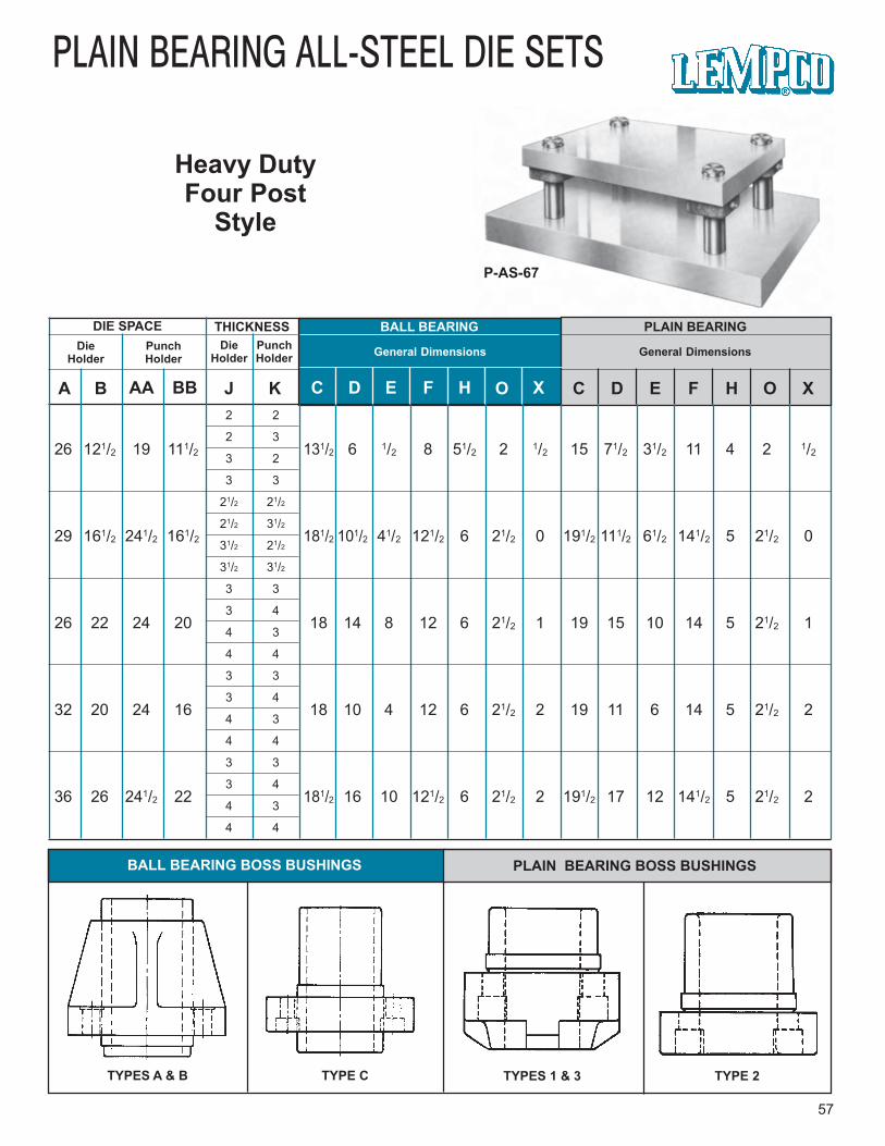
PLAIN BEARING ALL-STEEL DIE SETS
Heavy DutyFour Post
Style
P-AS-67
57
BALL BEARING BOSS BUSHINGS PLAIN BEARING BOSS BUSHINGS
TYPES A & B TYPE C TYPES 1 & 3 TYPE 2
PLAIN BEARING
General Dimensions
BALL BEARING
General Dimensions
THICKNESSDie
HolderPunchHolder
DieHolder
PunchHolder
DIE SPACE
A B AA BB J K C D E F H O X C D E F H O X2 2
2 3
3 2
3 3
21/2 21/2
21/2 31/2
31/2 21/2
31/2 31/2
3 3
3 4
4 3
4 4
3 3
3 4
4 3
4 4
3 3
3 4
4 3
4 4
26 121/2 19 111/2 131/2 6 1/2 8 51/2 2 1/2 15 71/2 31/2 11 4 2 1/2
29 161/2 241/2 161/2 181/2 101/2 41/2 121/2 6 21/2 0 191/2 111/2 61/2 141/2 5 21/2 0
26 22 24 20 18 14 8 12 6 21/2 1 19 15 10 14 5 21/2 1
32 20 24 16 18 10 4 12 6 21/2 2 19 11 6 14 5 21/2 2
36 26 241/2 22 181/2 16 10 121/2 6 21/2 2 191/2 17 12 141/2 5 21/2 2

58
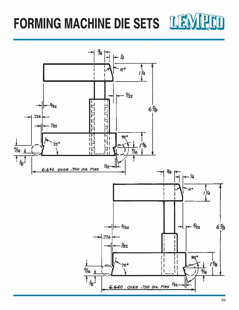
FORMING MACHINE DIE SETS
59
60
ALL STEEL DOVETAIL DIE SETS
For U.S. ToolMulti-SlideMachines
BB-95-M33-1
HOW TO ORDER . . .BALL BEARING SETS1. Select die set for proper machine model,
and in the required left to rightdimension.
2. Prefix to the catalog number the symbolBB. Example: BB-63-M28-2 is a BallBearing type, for Model 28, 61/2" x 39/16".Follow steps 3 through 7, below.
3. Specify quantity.4. Specify length “L” if other than listed
standard. For Ball Bearing sets this isMinimum Shut Height Dimension. For PlainBearing sets this dimension is length ofGuide Post “O”.
5 Specify type of bushing. Unless otherwisespecified, both Ball Bearing and PlainBearing sets will be furnished with Press
Fit Steel Sleeve Bushings.6. Specify any special machining required.
Unless otherwise specified, these sets willbe finished to the dimensions tabulated inthe chart and to the configurations shownin the schematic drawings.
7. Tell us how to ship; otherwise we will ship“best way” in our judgment.
MODELS28 & 35
MODEL33
PLAIN BEARING SETS1. Select die set for proper machine model,
and in the required left to rightdimension.
2. Prefix to the catalog number the symbolP. Example: P-63-M28-2 is a PlainBearing type, for Model 28, 61/2" x 39/16".Follow steps 3 through 7, below.
These die sets may not be returned for credit.
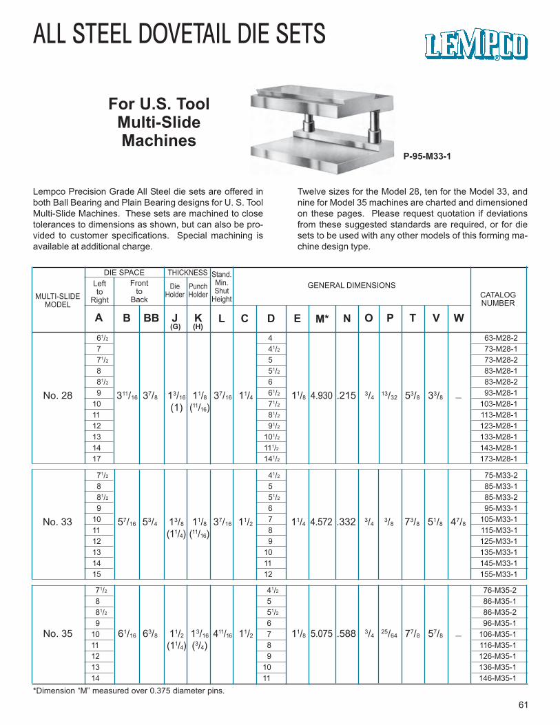
71/2 41/2 76-M35-2 8 5 86-M35-1 81/2 51/2 86-M35-2 9 6 96-M35-110 7 106-M35-111 8 116-M35-112 9 126-M35-113 10 136-M35-114 11 146-M35-1
71/2 41/2 75-M33-2 8 5 85-M33-1 81/2 51/2 85-M33-2 9 6 95-M33-110 7 105-M33-111 8 115-M33-112 9 125-M33-113 10 135-M33-114 11 145-M33-115 12 155-M33-1
61/2 4 63-M28-2 7 41/2 73-M28-1 71/2 5 73-M28-2 8 51/2 83-M28-1 81/2 6 83-M28-2 9 61/2 93-M28-110 71/2 103-M28-111 81/2 113-M28-112 91/2 123-M28-113 101/2 133-M28-114 111/2 143-M28-117 141/2 173-M28-1
Stand.Min.Shut
Height
ALL STEEL DOVETAIL DIE SETS
For U.S. ToolMulti-SlideMachines
P-95-M33-1
61*Dimension “M” measured over 0.375 diameter pins.
MULTI-SLIDEMODEL
DIE SPACELeftto
Right
Frontto
Back
DieHolder
PunchHolder
THICKNESSGENERAL DIMENSIONS
CATALOGNUMBER
A B BB J K L C D E M* N O P T V W(G) (H)
No. 28 311/16 37/8 13/16 11/8 37/16 11/4 11/8 4.930 .215 3/413/32 53/8 33/8 —
(1) (11/16)
No. 33 57/16 53/4 13/8 11/8 37/16 11/2 11/4 4.572 .332 3/43/8 73/8 51/8 47/8
(11/4) (11/16)
No. 35 61/16 63/8 11/2 13/16 411/16 11/2 11/8 5.075 .588 3/425/64 77/8 57/8 —
(11/4) (3/4)
Lempco Precision Grade All Steel die sets are offered inboth Ball Bearing and Plain Bearing designs for U. S. ToolMulti-Slide Machines. These sets are machined to closetolerances to dimensions as shown, but can also be pro-vided to customer specifications. Special machining isavailable at additional charge.
Twelve sizes for the Model 28, ten for the Model 33, andnine for Model 35 machines are charted and dimensionedon these pages. Please request quotation if deviationsfrom these suggested standards are required, or for diesets to be used with any other models of this forming ma-chine design type.

62
ALL STEEL DOVETAIL DIE SETS
For TorringtonVerti-SlideMachines
BB-92-V81
MODELV-81
MODELV-82
MODELV-80
Lempco manufactures All Steel Ball Bearing and Plain Bearing die sets for three models ofTorrington Verti-Slide Machines, the V-80, V-81, and V-82. These die sets are manufacturedPrecision Grade.
Three sizes of die sets for each of these machines are suggested, and in standardized formare dimensioned and charted on these pages. Completely special sets also are available.Request quotation. Special machining will be done at additional cost to details of customerprint.
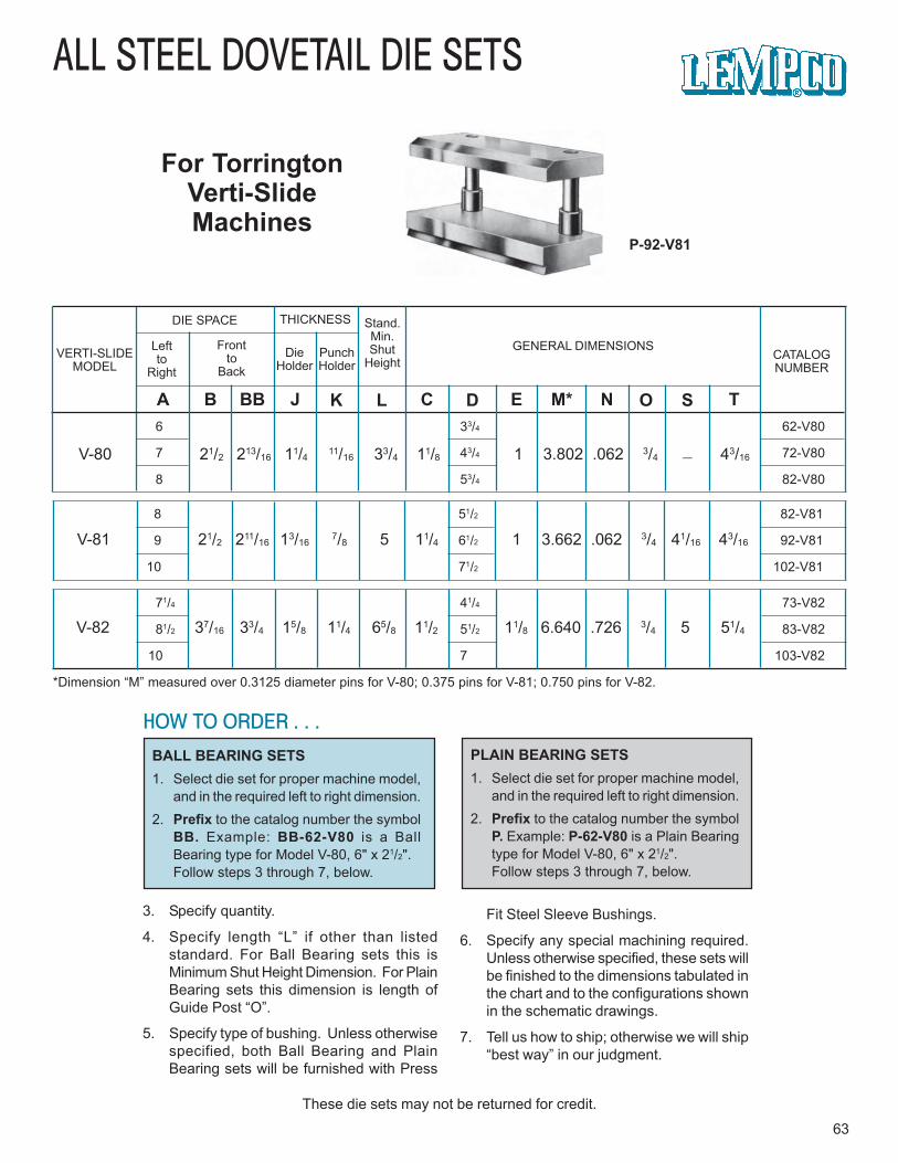
71/4 41/4 73-V82
81/2 51/2 83-V82
10 7 103-V82
8 51/2 82-V81
9 61/2 92-V81
10 71/2 102-V81
ALL STEEL DOVETAIL DIE SETS
For TorringtonVerti-SlideMachines
P-92-V81
63
HOW TO ORDER . . .
BALL BEARING SETS1. Select die set for proper machine model,
and in the required left to right dimension.2. Prefix to the catalog number the symbol
BB. Example: BB-62-V80 is a BallBearing type for Model V-80, 6" x 21/2".Follow steps 3 through 7, below.
3. Specify quantity.
4. Specify length “L” if other than listedstandard. For Ball Bearing sets this isMinimum Shut Height Dimension. For PlainBearing sets this dimension is length ofGuide Post “O”.
5. Specify type of bushing. Unless otherwisespecified, both Ball Bearing and PlainBearing sets will be furnished with Press
Fit Steel Sleeve Bushings.
6. Specify any special machining required.Unless otherwise specified, these sets willbe finished to the dimensions tabulated inthe chart and to the configurations shownin the schematic drawings.
7. Tell us how to ship; otherwise we will ship“best way” in our judgment.
PLAIN BEARING SETS1. Select die set for proper machine model,
and in the required left to right dimension.2. Prefix to the catalog number the symbol
P. Example: P-62-V80 is a Plain Bearingtype for Model V-80, 6" x 21/2".Follow steps 3 through 7, below.
These die sets may not be returned for credit.
VERTI-SLIDEMODEL
DIE SPACE THICKNESS Stand.Min.Shut
HeightLeftto
Right
Frontto
BackDie
HolderPunchHolder
GENERAL DIMENSIONSCATALOGNUMBER
A B BB J K L C D E M* N O S T
V-80 21/2 213/16 11/4 11/16 33/4 11/8 1 3.802 .062 3/4 — 43/16
V-81 21/2 211/16 13/167/8 5 11/4 1 3.662 .062 3/4 41/16 43/16
V-82 37/16 33/4 15/8 11/4 65/8 11/2 11/8 6.640 .726 3/4 5 51/4
*Dimension “M” measured over 0.3125 diameter pins for V-80; 0.375 pins for V-81; 0.750 pins for V-82.
6 33/4 62-V80
7 43/4 72-V80
8 53/4 82-V80

64
ALL STEEL DOVETAIL DIE SETS
For NilsonFourslideMachines
MODELS-3-F
MODELS-4-F
MODELS-2-F
MODELS-1-F
MODELS-0-F
BB-132-S2F
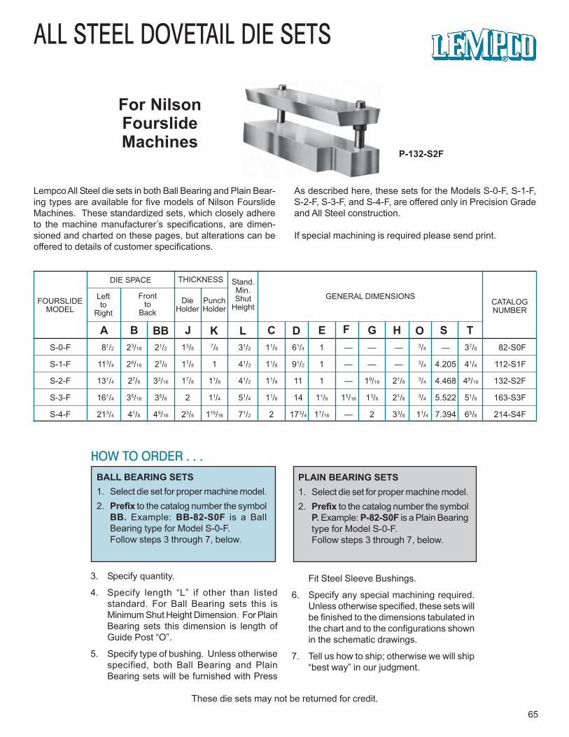
S-0-F 81/2 23/16 21/2 13/8 7/8 31/2 11/8 61/4 1 — — — 3/4 — 37/8 82-S0F
S-1-F 113/4 29/16 27/8 17/8 1 41/2 11/8 91/2 1 — — — 3/4 4.205 41/4 112-S1F
S-2-F 131/4 27/8 33/16 17/8 11/8 41/2 11/8 11 1 — 19/16 21/8 3/4 4.468 49/16 132-S2F
S-3-F 161/4 35/16 35/8 2 11/4 51/4 11/8 14 11/8 15/16 13/8 21/8 3/4 5.522 51/8 163-S3F
S-4-F 213/4 41/8 49/16 23/8 115/16 71/2 2 173/4 17/16 — 2 33/8 11/4 7.394 65/8 214-S4F
ALL STEEL DOVETAIL DIE SETS
For NilsonFourslideMachines
P-132-S2F
65
HOW TO ORDER . . .BALL BEARING SETS1. Select die set for proper machine model.2. Prefix to the catalog number the symbol
BB. Example: BB-82-S0F is a BallBearing type for Model S-0-F.Follow steps 3 through 7, below.
3. Specify quantity.
4. Specify length “L” if other than listedstandard. For Ball Bearing sets this isMinimum Shut Height Dimension. For PlainBearing sets this dimension is length ofGuide Post “O”.
5. Specify type of bushing. Unless otherwisespecified, both Ball Bearing and PlainBearing sets will be furnished with Press
Fit Steel Sleeve Bushings.
6. Specify any special machining required.Unless otherwise specified, these sets willbe finished to the dimensions tabulated inthe chart and to the configurations shownin the schematic drawings.
7. Tell us how to ship; otherwise we will ship“best way” in our judgment.
PLAIN BEARING SETS1. Select die set for proper machine model.2. Prefix to the catalog number the symbol
P. Example: P-82-S0F is a Plain Bearingtype for Model S-0-F.Follow steps 3 through 7, below.
These die sets may not be returned for credit.
FOURSLIDEMODEL
DIE SPACE THICKNESS Stand.Min.Shut
HeightLeftto
Right
Frontto
BackDie
HolderPunchHolder
GENERAL DIMENSIONSCATALOGNUMBER
A B BB J K L C D E F G O S TH
Lempco All Steel die sets in both Ball Bearing and Plain Bear-ing types are available for five models of Nilson FourslideMachines. These standardized sets, which closely adhereto the machine manufacturer’s specifications, are dimen-sioned and charted on these pages, but alterations can beoffered to details of customer specifications.
As described here, these sets for the Models S-0-F, S-1-F,S-2-F, S-3-F, and S-4-F, are offered only in Precision Gradeand All Steel construction.
If special machining is required please send print.
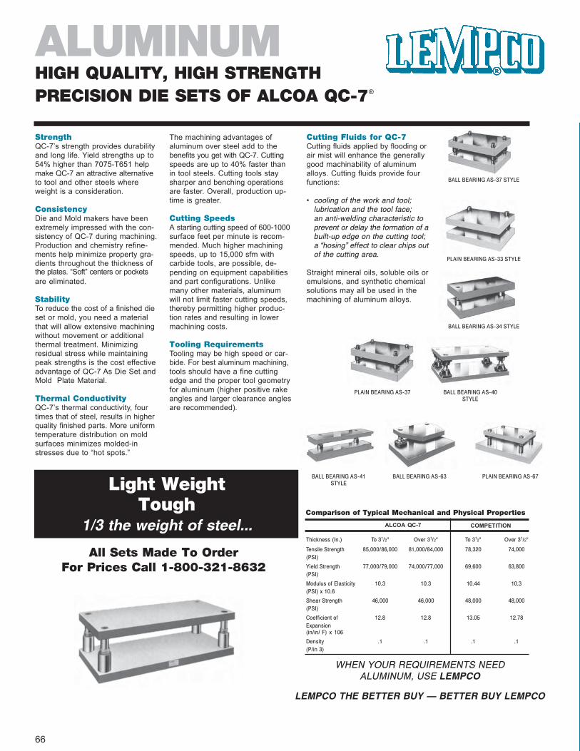
StrengthQC-7’s strength provides durabilityand long life. Yield strengths up to54% higher than 7075-T651 helpmake QC-7 an attractive alternativeto tool and other steels whereweight is a consideration.
ConsistencyDie and Mold makers have beenextremely impressed with the con-sistency of QC-7 during machining.Production and chemistry refine-ments help minimize property gra-dients throughout the thickness ofthe plates. “Soft” centers or pocketsare eliminated.
StabilityTo reduce the cost of a finished dieset or mold, you need a materialthat will allow extensive machiningwithout movement or additionalthermal treatment. Minimizingresidual stress while maintainingpeak strengths is the cost effectiveadvantage of QC-7 As Die Set andMold Plate Material.
Thermal ConductivityQC-7’s thermal conductivity, fourtimes that of steel, results in higherquality finished parts. More uniformtemperature distribution on moldsurfaces minimizes molded-instresses due to “hot spots.”
The machining advantages ofaluminum over steel add to thebenefits you get with QC-7. Cuttingspeeds are up to 40% faster thanin tool steels. Cutting tools staysharper and benching operationsare faster. Overall, production up-time is greater.
Cutting SpeedsA starting cutting speed of 600-1000surface feet per minute is recom-mended. Much higher machiningspeeds, up to 15,000 sfm withcarbide tools, are possible, de-pending on equipment capabilitiesand part configurations. Unlikemany other materials, aluminumwill not limit faster cutting speeds,thereby permitting higher produc-tion rates and resulting in lowermachining costs.
Tooling RequirementsTooling may be high speed or car-bide. For best aluminum machining,tools should have a fine cuttingedge and the proper tool geometryfor aluminum (higher positive rakeangles and larger clearance anglesare recommended).
Cutting Fluids for QC-7Cutting fluids applied by flooding orair mist will enhance the generallygood machinability of aluminumalloys. Cutting fluids provide fourfunctions:
• cooling of the work and tool;lubrication and the tool face;an anti-welding characteristic toprevent or delay the formation of abuilt-up edge on the cutting tool;a “hosing” effect to clear chips outof the cutting area.
Straight mineral oils, soluble oils oremulsions, and synthetic chemicalsolutions may all be used in themachining of aluminum alloys.
Light WeightTough
1/3 the weight of steel...
All Sets Made To OrderFor Prices Call 1-800-321-8632
WHEN YOUR REQUIREMENTS NEEDALUMINUM, USE LEMPCO
LEMPCO THE BETTER BUY — BETTER BUY LEMPCO
Comparison of Typical Mechanical and Physical Properties
Thickness (In.)
Tensile Strength(PSI)
Yield Strength(PSI)
Modulus of Elasticity(PSI) x 10.6
Shear Strength(PSI)
Coefficient ofExpansion(in/in/ F) x 106
Density(P/in 3)
To 31/2"
85,000/86,000(PSI)
77,000/79,000(PSI)
10.3(PSI) x 10.6
46,000(PSI)
12.8Expansion
(in/in/ F) x 106
.1(P/in 3)
Over 31/2"
81,000/84,000(PSI)
74,000/77,000(PSI)
10.3(PSI) x 10.6
46,000(PSI)
12.8Expansion
(in/in/ F) x 106
.1(P/in 3)
To 312"
78,320(PSI)
69,600(PSI)
10.44(PSI) x 10.6
48,000(PSI)
13.05Expansion
(in/in/ F) x 106
.1(P/in 3)
Over 31/2"
74,000(PSI)
63,800(PSI)
10.3(PSI) x 10.6
48,000(PSI)
12.78Expansion(in/in/ F) x
.1(P/in 3)
ALCOA QC-7 COMPETITION
BALL BEARING AS-40STYLE
PLAIN BEARING AS-37
PLAIN BEARING AS-33 STYLE
BALL BEARING AS-41STYLE
BALL BEARING AS-37 STYLE
BALL BEARING AS-34 STYLE
PLAIN BEARING AS-67BALL BEARING AS-63
ALUMINUMHIGH QUALITY, HIGH STRENGTHPRECISION DIE SETS OF ALCOA QC-7®
66
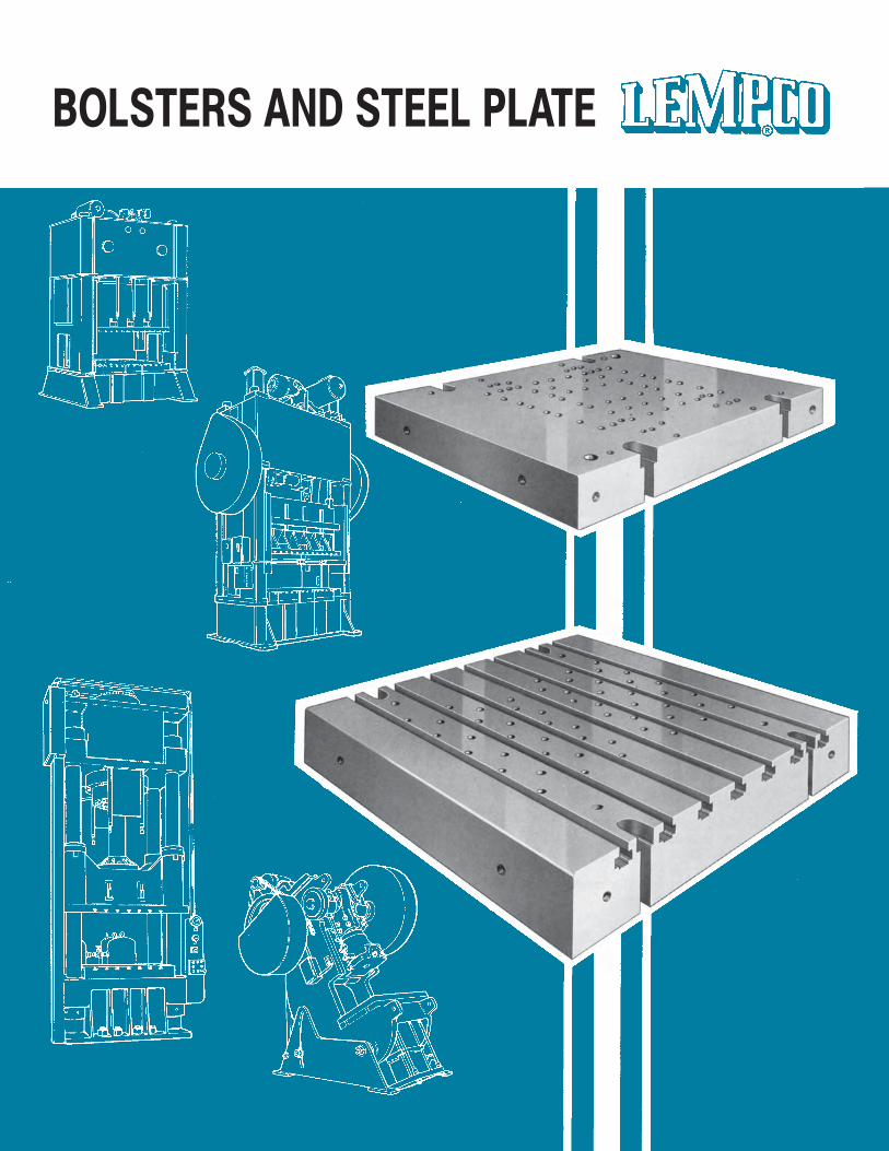
BOLSTERS AND STEEL PLATE
67
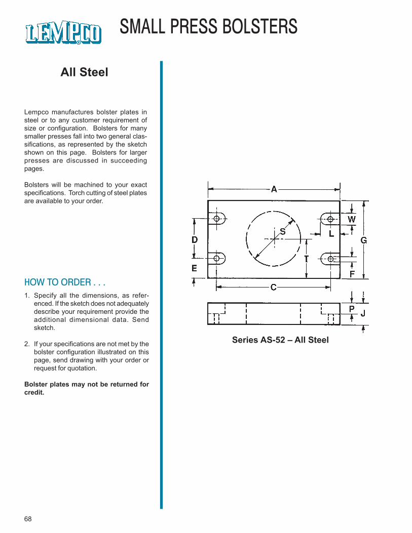
68
SMALL PRESS BOLSTERS
Lempco manufactures bolster plates insteel or to any customer requirement ofsize or configuration. Bolsters for manysmaller presses fall into two general clas-sifications, as represented by the sketchshown on this page. Bolsters for largerpresses are discussed in succeedingpages.
Bolsters will be machined to your exactspecifications. Torch cutting of steel platesare available to your order.
Series AS-52 – All Steel
All Steel
HOW TO ORDER . . .1. Specify all the dimensions, as refer-
enced. If the sketch does not adequatelydescribe your requirement provide theadditional dimensional data. Sendsketch.
2. If your specifications are not met by thebolster configuration illustrated on thispage, send drawing with your order orrequest for quotation.
Bolster plates may not be returned forcredit.
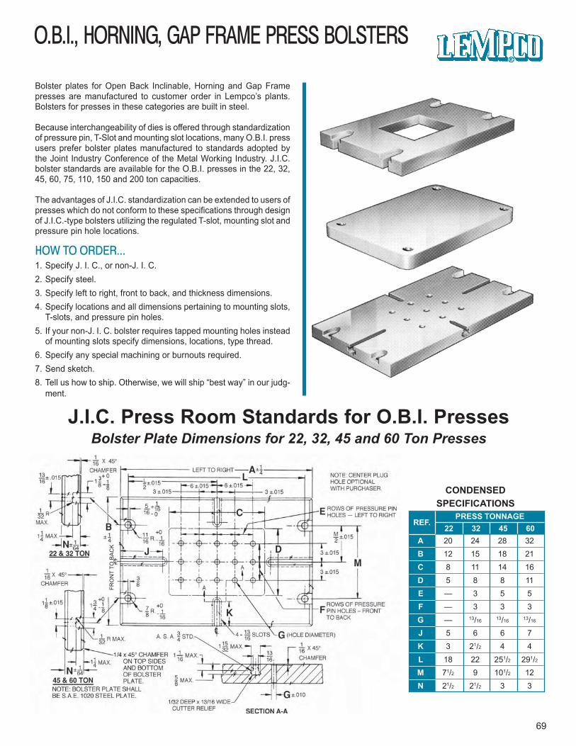
O.B.I., HORNING, GAP FRAME PRESS BOLSTERS
69
FRO
NT
TO B
AC
K
Bolster plates for Open Back Inclinable, Horning and Gap Framepresses are manufactured to customer order in Lempco’s plants.Bolsters for presses in these categories are built in steel.
Because interchangeability of dies is offered through standardizationof pressure pin, T-Slot and mounting slot locations, many O.B.I. pressusers prefer bolster plates manufactured to standards adopted bythe Joint Industry Conference of the Metal Working Industry. J.I.C.bolster standards are available for the O.B.I. presses in the 22, 32,45, 60, 75, 110, 150 and 200 ton capacities.
The advantages of J.I.C. standardization can be extended to users ofpresses which do not conform to these specifications through designof J.I.C.-type bolsters utilizing the regulated T-slot, mounting slot andpressure pin hole locations.
HOW TO ORDER...1. Specify J. I. C., or non-J. I. C.2. Specify steel.3. Specify left to right, front to back, and thickness dimensions.4. Specify locations and all dimensions pertaining to mounting slots,
T-slots, and pressure pin holes.5. If your non-J. I. C. bolster requires tapped mounting holes instead
of mounting slots specify dimensions, locations, type thread.6. Specify any special machining or burnouts required.7. Send sketch.8. Tell us how to ship. Otherwise, we will ship “best way” in our judg-
ment.
J.I.C. Press Room Standards for O.B.I. PressesBolster Plate Dimensions for 22, 32, 45 and 60 Ton Presses
PRESS TONNAGEREF.
22 32 45 60ABCDEFGJKLMN
20 24 28 3212 15 18 218 11 14 165 8 8 11— 3 5 5— 3 3 3— 13/16 13/16 13/16
5 6 6 73 21/2 4 4
18 22 251/2 291/2
71/2 9 101/2 1221/2 21/2 3 3
CONDENSEDSPECIFICATIONS
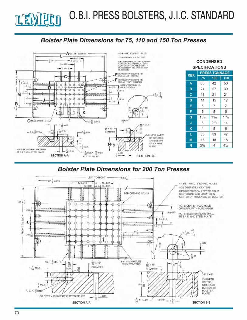
70
O.B.I. PRESS BOLSTERS, J.I.C. STANDARD
Bolster Plate Dimensions for 75, 110 and 150 Ton Presses
PRESS TONNAGEREF.
75 100 150ABCDEFGJKLMN
36 42 5024 27 3018 21 2114 15 175 7 75 5 5
11/16 11/16 11/16
8 91/2 144 5 6
33 39 4718 18 1831/2 4 41/2
CONDENSEDSPECIFICATIONS
Bolster Plate Dimensions for 200 Ton Presses
FRO
NT
TO B
AC
K
FRO
NT
TO B
AC
K
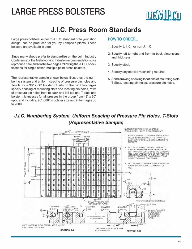
LARGE PRESS BOLSTERS
71
J.I.C. Numbering System, Uniform Spacing of Pressure Pin Holes, T-Slots(Representative Sample)
Large press bolsters, either to J. I. C. standard or to your shopdesign, can be produced for you by Lempco’s plants. Thesebolsters are available in steel.
Since many shops prefer to standardize on the Joint IndustryConference of the Metalworking Industry recommendations, wereproduce here and on the two pages following the J. I. C. speci-fications for single action-multiple point press bolsters.
The representative sample shown below illustrates the num-bering system and uniform spacing of pressure pin holes andT-slots for a 96" x 66" bolster. Charts on the next two pagesspecify spacing of mounting slots and locating pin holes, rowsof pressure pin holes front to back and left to right. T-slots andbolster thicknesses for all presses in the group from 48" x 30"up to and including 96" x 66" in bolster size and in tonnages upto 2000.
J.I.C. Press Room StandardsHOW TO ORDER...
1. Specify J. I. C., or non-J. I. C.
2. Specify left to right and front to back dimensions,and thickness.
3. Specify steel.
4. Specify any special machining required.
5. Send drawing showing locations of mounting slots,T-Slots, locating pin holes, pressure pin holes.
FRO
NT
TO B
AC
K
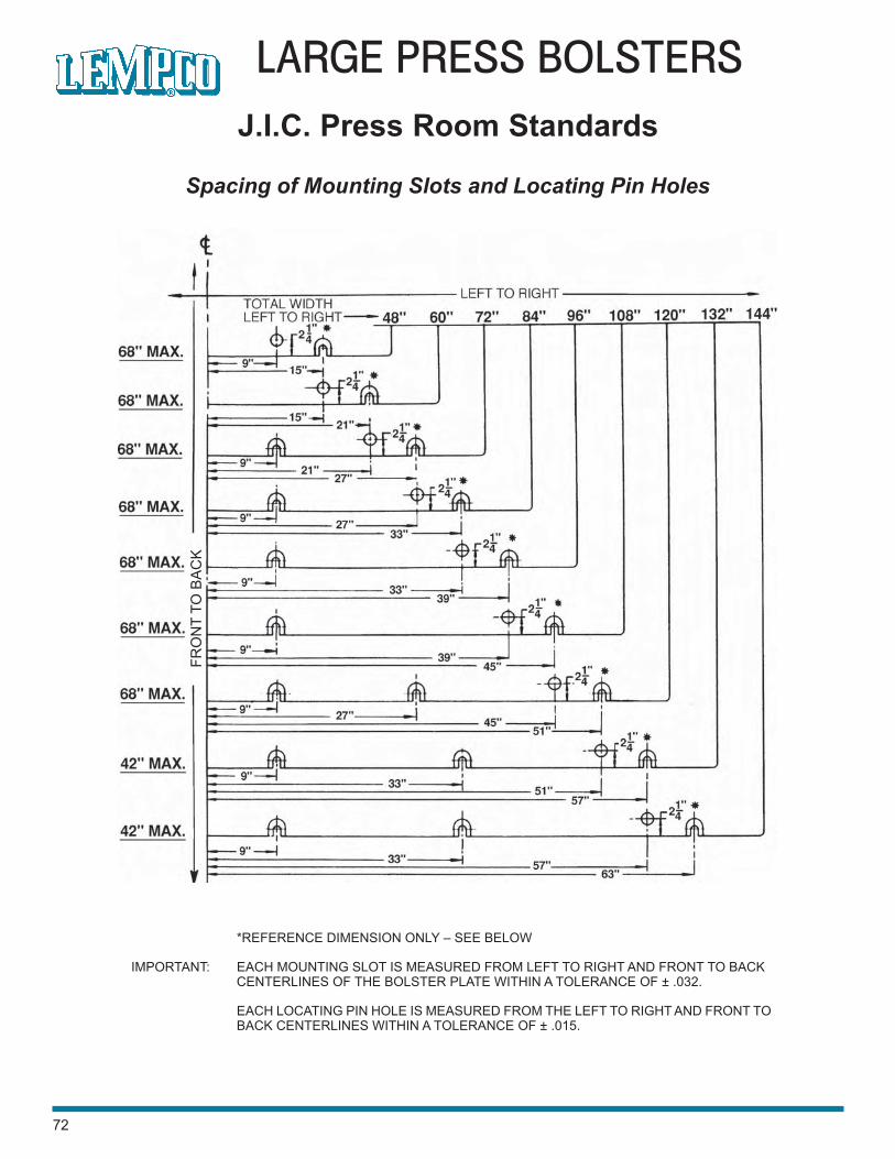
72
LARGE PRESS BOLSTERS
Spacing of Mounting Slots and Locating Pin Holes
J.I.C. Press Room Standards
*REFERENCE DIMENSION ONLY – SEE BELOW
IMPORTANT: EACH MOUNTING SLOT IS MEASURED FROM LEFT TO RIGHT AND FRONT TO BACKCENTERLINES OF THE BOLSTER PLATE WITHIN A TOLERANCE OF ± .032.
EACH LOCATING PIN HOLE IS MEASURED FROM THE LEFT TO RIGHT AND FRONT TOBACK CENTERLINES WITHIN A TOLERANCE OF ± .015.
FRO
NT
TO B
AC
K
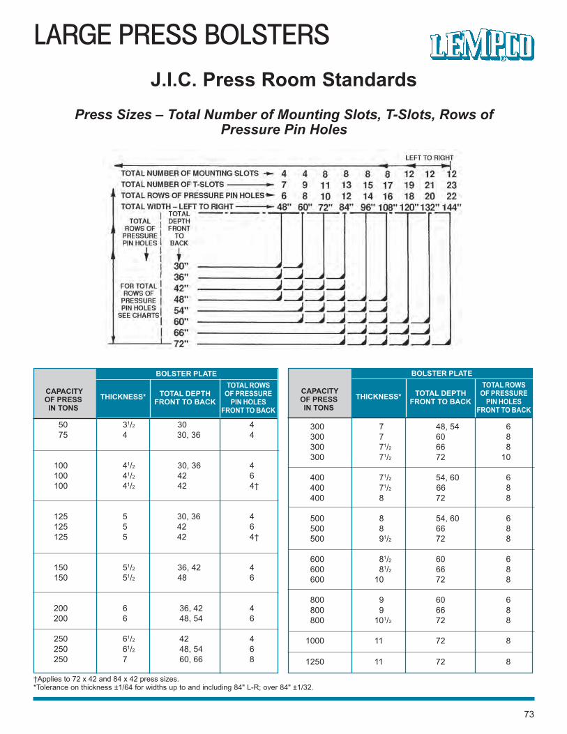
300 7 48, 54 6300 7 60 8300 71/2 66 8300 71/2 72 10
400 71/2 54, 60 6400 71/2 66 8400 8 72 8
500 8 54, 60 6500 8 66 8500 91/2 72 8
600 81/2 60 6600 81/2 66 8600 10 72 8
800 9 60 6800 9 66 8800 101/2 72 8
1000 11 72 8
1250 11 72 8
LARGE PRESS BOLSTERS
73
Press Sizes – Total Number of Mounting Slots, T-Slots, Rows ofPressure Pin Holes
J.I.C. Press Room Standards
†Applies to 72 x 42 and 84 x 42 press sizes.*Tolerance on thickness ±1/64 for widths up to and including 84" L-R; over 84" ±1/32.
CAPACITYOF PRESSIN TONS
BOLSTER PLATE
THICKNESS* TOTAL DEPTHFRONT TO BACK
TOTAL ROWSOF PRESSURE
PIN HOLESFRONT TO BACK
CAPACITYOF PRESSIN TONS
BOLSTER PLATE
THICKNESS* TOTAL DEPTHFRONT TO BACK
TOTAL ROWSOF PRESSURE
PIN HOLESFRONT TO BACK
50 31/2 30 475 4 30, 36 4
100 41/2 30, 36 4100 41/2 42 6100 41/2 42 4†
125 5 30, 36 4125 5 42 6125 5 42 4†
150 51/2 36, 42 4150 51/2 48 6
200 6 36, 42 4200 6 48, 54 6
250 61/2 42 4250 61/2 48, 54 6250 7 60, 66 8
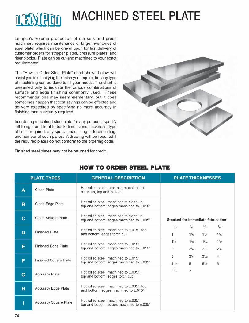
74
MACHINED STEEL PLATE
Lempco’s volume production of die sets and pressmachinery requires maintenance of large inventories ofsteel plate, which can be drawn upon for fast delivery ofcustomer orders for stripper plates, pressure plates, andriser blocks. Plate can be cut and machined to your exactrequirements.
The “How to Order Steel Plate” chart shown below wiIIassist you in specifying the finish you require, but any typeof machining can be done to fill your needs. The chart ispresented only to indicate the various combinations ofsurface and edge finishing commonly used. Theserecommendations may seem elementary, but it doessometimes happen that cost savings can be effected anddelivery expedited by specifying no more accuracy infinishing than is actually required.
In ordering machined steel plate for any purpose, specifyleft to right and front to back dimensions, thickness, typeof finish required, any special machining or torch cutting,and number of such plates. A drawing wiII be required ifthe required plates do not conform to the ordering code.
Finished steel plates may not be returned for credit.
HOW TO ORDER STEEL PLATE
PLATE TYPES GENERAL DESCRIPTION PLATE THICKNESSES
A
B
C
D
E
F
G
H
I
Clean Plate
Clean Edge Plate
Clean Square Plate
Finished Plate
Finished Edge Plate
Finished Square Plate
Accuracy Plate
Accuracy Edge Plate
Accuracy Square Plate
Hot rolled steel, torch cut, machined toclean up, top and bottom
Hot rolled steel, machined to clean up,top and bottom; edges machined to ±.015"
Hot rolled steel, machined to clean up,top and bottom; edges machined to ±.005"
Hot rolled steel, machined to ±.015", topand bottom; edges torch cut
Hot rolled steel, machined to ±.015",top and bottom; edges machined to ±.015"
Hot rolled steel, machined to ±.015",top and bottom; edges machined to ±.005"
Hot rolled steel, machined to ±.005",top and bottom; edges torch cut
Hot rolled steel, machined to ±.005", topand bottom; edges machined to ±.015"
Hot rolled steel, machined to ±.005",top and bottom; edges machined to ±.005"
Stocked for immediate fabrication:
1/2 5/8 3/4 7/8
1 11/8 11/4 13/8
11/2 15/8 13/4 17/8
2 21/4 21/2 23/4
3 31/4 31/2 4
41/2 5 51/2 6
61/2 7
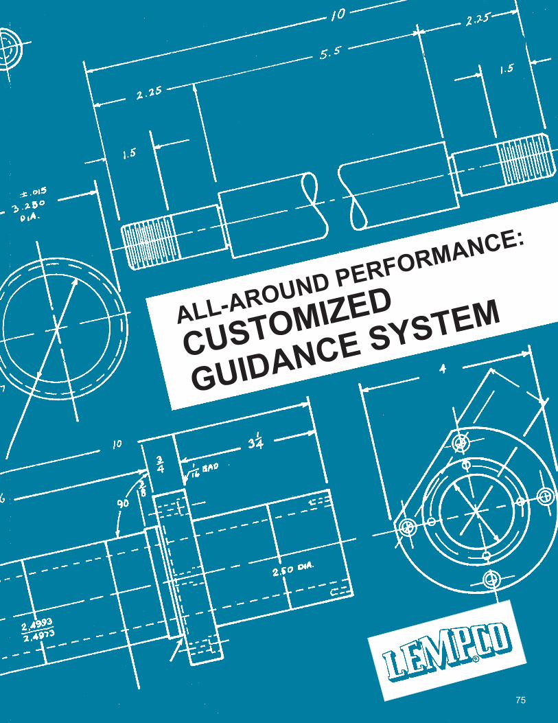
75
ALL-AROUND PERFORMANCE:
CUSTOMIZED
GUIDANCE SYSTEM
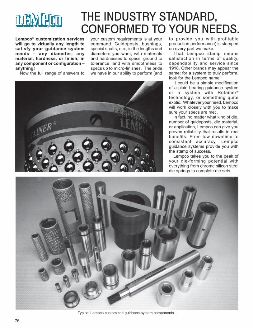
76
THE INDUSTRY STANDARD,CONFORMED TO YOUR NEEDS.
Typical Lempco customized guidance system components.
Lempco® customization serviceswill go to virtually any length tosatisfy your guidance systemneeds – any diameter; anymaterial, hardness, or finish; inany component or configuration –anything!
Now the full range of answers to
your custom requirements is at yourcommand. Guideposts, bushings,special shafts, etc., in the lengths anddiameters you want, with materialsand hardnesses to specs, ground totolerance, and with smoothness tospecs up to micro-finishes. The pridewe have in our ability to perform (and
to provide you with profitableproduction performance) is stampedon every part we make.
That Lempco stamp meanssatisfaction in terms of quality,dependability and service since1918. Other brands may appear thesame: for a system to truly perform,look for the Lempco name.
It could be a simple modificationof a plain bearing guidance systemor a system with Rotainer®
technology, or something quiteexotic. Whatever your need, Lempcowill work closely with you to makesure your specs are met .
In fact, no matter what kind of die,number of guideposts, die material,or application, Lempco can give youproven reliability that results in realbenefits. From low downtime toconsistent accuracy, Lempcoguidance systems provide you withthe stamp of success.
Lempco takes you to the peak ofyour die-forming potential witheverything from chrome silicon steeldie springs to complete die sets.
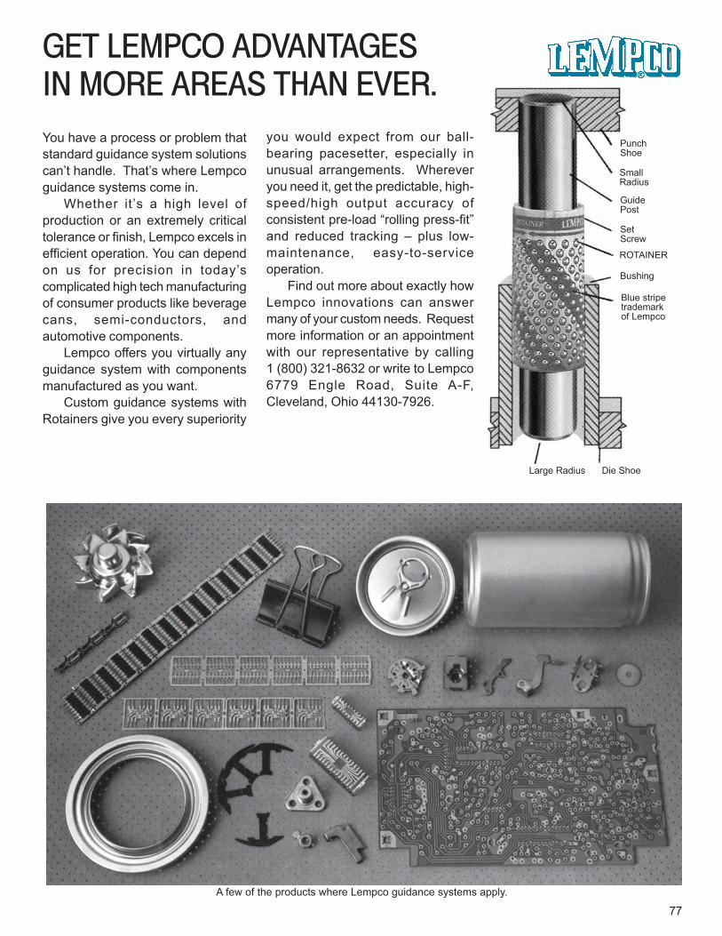
GET LEMPCO ADVANTAGESIN MORE AREAS THAN EVER.
77A few of the products where Lempco guidance systems apply.
You have a process or problem thatstandard guidance system solutionscan’t handle. That’s where Lempcoguidance systems come in.
Whether it’s a high level ofproduction or an extremely criticaltolerance or finish, Lempco excels inefficient operation. You can dependon us for precision in today’scomplicated high tech manufacturingof consumer products like beveragecans, semi-conductors, andautomotive components.
Lempco offers you virtually anyguidance system with componentsmanufactured as you want.
Custom guidance systems withRotainers give you every superiority
you would expect from our ball-bearing pacesetter, especially inunusual arrangements. Whereveryou need it, get the predictable, high-speed/high output accuracy ofconsistent pre-load “rolling press-fit”and reduced tracking – plus low-maintenance, easy-to-serviceoperation.
Find out more about exactly howLempco innovations can answermany of your custom needs. Requestmore information or an appointmentwith our representative by calling1 (800) 321-8632 or write to Lempco6779 Engle Road, Suite A-F,Cleveland, Ohio 44130-7926.
PunchShoe
SmallRadius
GuidePost
SetScrew
ROTAINER
Bushing
Blue stripetrademarkof Lempco
Large Radius Die Shoe
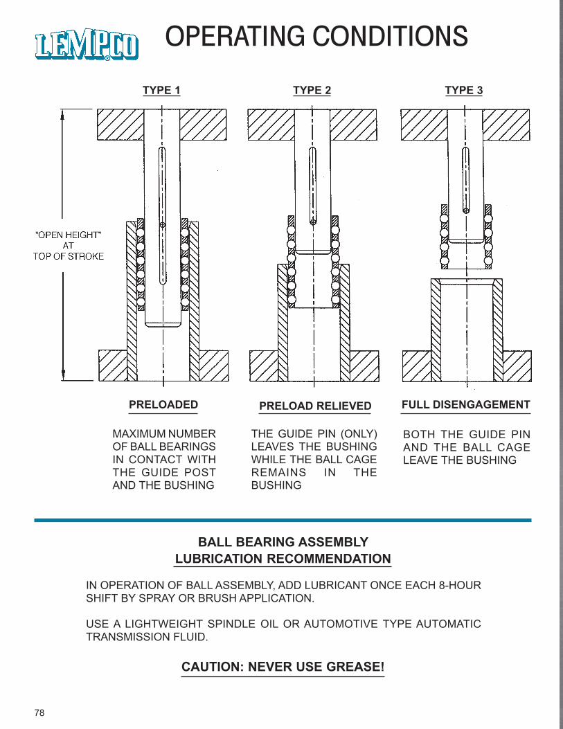
78
OPERATING CONDITIONS
TYPE 1 TYPE 2 TYPE 3
PRELOADED
MAXIMUM NUMBEROF BALL BEARINGSIN CONTACT WITHTHE GUIDE POSTAND THE BUSHING
PRELOAD RELIEVED
THE GUIDE PIN (ONLY)LEAVES THE BUSHINGWHILE THE BALL CAGEREMAINS IN THEBUSHING
FULL DISENGAGEMENT
BOTH THE GUIDE PINAND THE BALL CAGELEAVE THE BUSHING
BALL BEARING ASSEMBLYLUBRICATION RECOMMENDATION
IN OPERATION OF BALL ASSEMBLY, ADD LUBRICANT ONCE EACH 8-HOURSHIFT BY SPRAY OR BRUSH APPLICATION.
USE A LIGHTWEIGHT SPINDLE OIL OR AUTOMOTIVE TYPE AUTOMATICTRANSMISSION FLUID.
CAUTION: NEVER USE GREASE!
MetricCatalog
Available
79
Die Set Components &Customized Guidance SystemsDie Set Components &Customized Guidance Systems
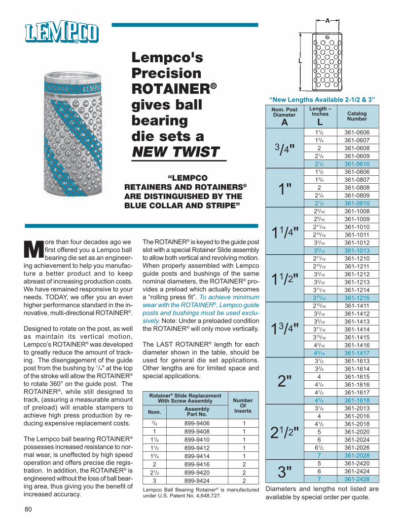
80
Lempco'sPrecisionROTAINER®
gives ballbearingdie sets aNEW TWIST
“LEMPCORETAINERS AND ROTAINERS®
ARE DISTINGUISHED BY THEBLUE COLLAR AND STRIPE”
ore than four decades ago wefirst offered you a Lempco ballbearing die set as an engineer-
ing achievement to help you manufac-ture a better product and to keepabreast of increasing production costs.We have remained responsive to yourneeds. TODAY, we offer you an evenhigher performance standard in the in-novative, multi-directional ROTAINER®.
Designed to rotate on the post, as wellas maintain its vertical motion,Lempco’s ROTAINER® was developedto greatly reduce the amount of track-ing. The disengagement of the guidepost from the bushing by 1/4" at the topof the stroke will allow the ROTAINER®
to rotate 360° on the guide post. TheROTAINER®, while still designed totrack, (assuring a measurable amountof preload) will enable stampers toachieve high press production by re-ducing expensive replacement costs.
The Lempco ball bearing ROTAINER®
possesses increased resistance to nor-mal wear, is uneffected by high speedoperation and offers precise die regis-tration. In addition, the ROTAINER® isengineered without the loss of ball bear-ing area, thus giving you the benefit ofincreased accuracy.
The ROTAINER® is keyed to the guide postslot with a special Rotainer Slide assemblyto allow both vertical and revolving motion.When properly assembled with Lempcoguide posts and bushings of the samenominal diameters, the ROTAINER® pro-vides a preload which actually becomesa “rolling press fit”. To achieve minimumwear with the ROTAINER®, Lempco guideposts and bushings must be used exclu-sively. Note: Under a preloaded conditionthe ROTAINER® will only move vertically.
The LAST ROTAINER® length for eachdiameter shown in the table, should beused for general die set applications.Other lengths are for limited space andspecial applications.
M
Lempco Ball Bearing Rotainer® is manufacturedunder U.S. Patent No. 4,648,727.
Rotainer® Slide ReplacementWith Screw Assembly
Nom. AssemblyPart No.
NumberOf
Inserts
3/4 899-9406 11 899-9408 1
11/4 899-9410 111/2 899-9412 113/4 899-9414 12 899-9416 2
21/2 899-9420 23 899-9424 2
“New Lengths Available 2-1/2 & 3”
Diameters and lengths not listed areavailable by special order per quote.
Nom. PostDiameter
Length –Inches Catalog
NumberA L
3/4"
1"
11/4"
11/2"
13/4"
2"
21/2"
3"
11/2 361-060613/4 361-06072 361-0608
21/4 361-060921/2 361-061011/2 361-080613/4 361-08072 361-0808
21/4 361-080921/2 361-081023/16 361-100825/16 361-1009211/16 361-1010215/16 361-101133/16 361-101235/16 361-1013211/16 361-1210215/16 361-121133/16 361-121235/16 361-1213311/16 361-1214315/16 361-1215215/16 361-141133/16 361-141235/16 361-1413311/16 361-1414315/16 361-141543/16 361-141645/16 361-141731/2 361-161333/4 361-16144 361-1615
41/4 361-161641/2 361-161743/4 361-161831/4 361-20134 361-2016
41/2 361-20185 361-20206 361-2024
61/2 361-20267 361-20285 361-24206 361-24247 361-2428
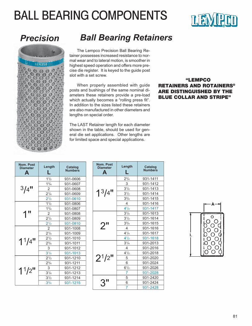
23/4 931-14113 931-1412
31/4 931-141331/2 931-141433/4 931-14154 931-1416
41/4 931-141731/4 931-161331/2 931-161433/4 931-16154 931-1616
41/4 931-161741/2 931-161831/4 931-20134 931-2016
41/2 931-20185 931-20206 931-2024
61/2 931-20267 931-20285 931-24206 931-24247 931-2428
BALL BEARING COMPONENTS
81
Ball Bearing RetainersPrecision
“LEMPCORETAINERS AND ROTAINERS®
ARE DISTINGUISHED BY THEBLUE COLLAR AND STRIPE”
The Lempco Precision Ball Bearing Re-tainer possesses increased resistance to nor-mal wear and to lateral motion, is smoother inhighest speed operation and offers more pre-cise die register. It is keyed to the guide postslot with a set screw.
When properly assembled with guideposts and bushings of the same nominal di-ameters these retainers provide a pre-loadwhich actually becomes a “rolling press fit”.In addition to the sizes listed these retainersare also manufactured in other diameters andlengths on special order.
The LAST Retainer length for each diametershown in the table, should be used for gen-eral die set applications. Other lengths arefor limited space and special applications.
Nom. PostDiameter Length Catalog
NumbersA L
3/4"
1"
11/4"
11/2"
11/2 931-060613/4 931-06072 931-0608
21/4 931-060921/2 931-061011/2 931-080613/4 931-08072 931-0808
21/4 931-080921/2 931-08102 931-1008
21/4 931-100921/2 931-101023/4 931-10113 931-1012
31/4 931-101321/2 931-121023/4 931-12113 931-1212
31/4 931-121331/2 931-121433/4 931-1215
Nom. PostDiameter Length Catalog
NumbersA L
13/4"
2"
21/2"
3"
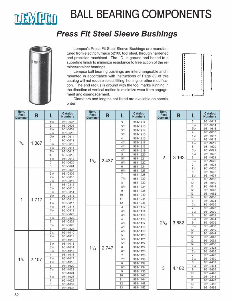
82
BALL BEARING COMPONENTS
Press Fit Steel Sleeve BushingsLempco's Press Fit Steel Sleeve Bushings are manufac-
tured from electric furnace 52100 tool steel, through hardenedand precision machined. The I.D. is ground and honed to asuperfine finish to minimize resistance to free action of the re-tainer/rotainer bearings.
Lempco ball bearing bushings are interchangeable and ifmounted in accordance with instructions of Page 89 of thiscatalog will not require select fitting, honing, or other modifica-tion. The end radius is ground with the tool marks running inthe direction of vertical motion to minimize wear from engage-ment and disengagement.
Diameters and lengths not listed are available on specialorder.
Nom.Post
DiameterCatalog
NumbersLBNom.Post
DiameterCatalog
NumbersLBNom.Post
DiameterCatalog
NumbersLB
3/4 1.387
1 1.717
11/4 2.107
11/2 2.437
13/4 2.747
2 3.162
21/2 3.682
3 4.182
13/4 961-06072 961-060821/4 961-060921/2 961-061023/4 961-06113 961-061231/4 961-061331/2 961-061433/4 961-06154 961-061641/2 961-06185 961-06206 961-06242 961-080821/4 961-080921/2 961-081023/4 961-08113 961-081231/4 961-081331/2 961-081433/4 961-08154 961-081641/4 961-081741/2 961-081843/4 961-08195 961-082051/2 961-08226 961-082461/2 961-08267 961-082821/2 961-101023/4 961-10113 961-101231/4 961-101331/2 961-101433/4 961-10154 961-101641/4 961-101741/2 961-10185 961-102051/2 961-10226 961-102461/2 961-10267 961-10288 961-10329 961-1036
3 961-1212 31/4 961-1213 31/2 961-1214 33/4 961-1215 4 961-1216 41/4 961-1217 41/2 961-1218 43/4 961-1219 5 961-1220 51/4 961-1221 51/2 961-1222 6 961-1224 61/2 961-1226 7 961-1228 71/2 961-1230 8 961-1232 81/2 961-1234 9 961-123610 961-124011 961-124412 961-1248 3 961-1412 31/2 961-1414 33/4 961-1415 4 961-1416 41/4 961-1417 41/2 961-1418 43/4 961-1419 5 961-1420 51/4 961-1421 51/2 961-1422 6 961-1424 61/2 961-1426 7 961-1428 71/2 961-1430 8 961-1432 81/2 961-1434 9 961-143610 961-144011 961-144412 961-144813 961-1452
3 961-1612 31/2 961-1614 33/4 961-1615 4 961-1616 41/4 961-1617 41/2 961-1618 43/4 961-1619 5 961-1620 51/4 961-1621 51/2 961-1622 6 961-1624 61/2 961-1626 7 961-1628 71/2 961-1630 8 961-1632 81/2 961-1634 9 961-163610 961-164011 961-164412 961-164813 961-165214 961-1656 6 961-2024 61/2 961-2026 7 961-2028 71/2 961-2030 8 961-2032 81/2 961-2034 9 961-2036 91/2 961-203810 961-204011 961-204412 961-204813 961-205214 961-2056 6 961-2424 61/2 961-2426 7 961-2428 71/2 961-2430 8 961-2432 81/2 961-2434 9 961-243610 961-244011 961-244412 961-244813 961-245214 961-2456
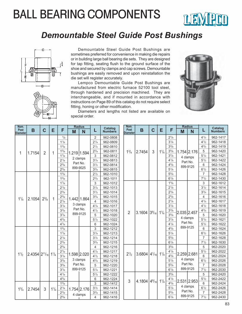
BALL BEARING COMPONENTS
83
Demountable Steel Guide Post BushingsDemountable Steel Guide Post Bushings are
sometimes preferred for convenience in making die repairsor in building large ball bearing die sets. They are designedfor tap fitting, seating flush to the ground surface of theshoe and secured by clamps and cap screws. Demountablebushings are easily removed and upon reinstallation thedie set will register accurately.
Lempco Demountable Guide Post Bushings aremanufactured from electric furnace 52100 tool steel,through hardened and precision machined. They areinterchangeable, and if mounted in accordance withinstructions on Page 89 of this catalog do not require selectfitting, honing or other modification.
Diameters and lengths not listed are available onspecial order.
Nom.Post
Diameter B C E FRadius
M NCatalog
NumbersLNom.Post
Diameter B C E FRadius
M NCatalog
NumbersL
1 1.7154 2 1 1.219 1.5942 clampsPart No.899-9025
11/4 2.1054 23/8 1 1.442 1.8643 clampsPart No.899-9125
11/2 2.4354 211/16 11/4 1.598 2.0203 clampsPart No.899-9125
13/4 2.7454 3 11/4 1.754 2.1764 clamps
13/4 2.7454 3 11/4 1.754 2.1764 clampsPart No.899-9125
2 3.1604 39/16 11/4 2.035 2.4574 clampsPart No.899-9125
21/2 3.6804 41/16 11/4 2.259 2.6814 clampsPart No.899-9125
3 4.1804 49/16 11/4 2.531 2.9534 clampsPart No.899-9125
7/8 2 962-080811/8 21/4 962-080913/8 21/2 962-081015/8 23/4 962-081117/8 3 962-081221/8 31/4 962-081323/8 31/2 962-081425/8 33/4 962-081513/8 21/2 962-101015/8 23/4 962-101117/8 3 962-101221/8 31/4 962-101323/8 31/2 962-101425/8 33/4 962-101527/8 4 962-101631/8 41/4 962-101733/8 41/2 962-101837/8 5 962-102043/8 51/2 962-102247/8 6 962-102415/8 3 962-121217/8 31/4 962-121321/8 31/2 962-121423/8 33/4 962-121525/8 4 962-121627/8 41/4 962-121731/8 41/2 962-121833/8 43/4 962-121935/8 5 962-122037/8 51/4 962-122141/8 51/2 962-122245/8 6 962-122415/8 3 962-141221/8 31/2 962-141423/8 33/4 962-141525/8 4 962-1416
27/8 41/4 962-141731/8 41/2 962-141833/8 43/4 962-141935/8 5 962-142037/8 51/4 962-142141/8 51/2 962-142245/8 6 962-142451/8 61/2 962-142655/8 7 962-142861/8 71/2 962-143015/8 3 962-161221/8 31/2 962-161423/8 33/4 962-161525/8 4 962-161627/8 41/4 962-161731/8 41/2 962-161833/8 43/4 962-161935/8 5 962-162037/8 51/4 962-162141/8 51/2 962-162245/8 6 962-162451/8 61/2 962-162655/8 7 962-162861/8 71/2 962-163035/8 5 962-202041/8 51/2 962-202245/8 6 962-202451/8 61/2 962-202655/8 7 962-202861/8 71/2 962-203035/8 5 962-242041/8 51/2 962-242245/8 6 962-242451/8 61/2 962-242655/8 7 962-242861/8 71/2 962-2430
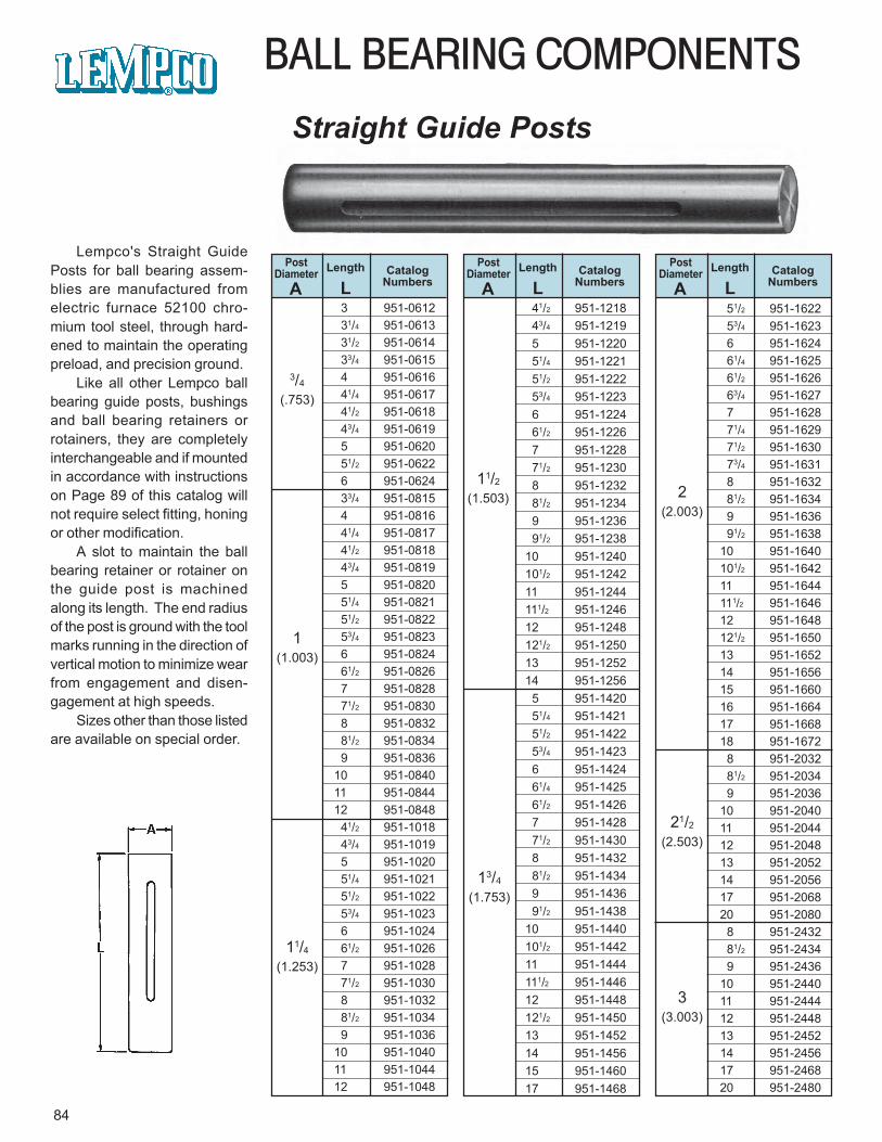
BALL BEARING COMPONENTS
Straight Guide Posts
Lempco's Straight GuidePosts for ball bearing assem-blies are manufactured fromelectric furnace 52100 chro-mium tool steel, through hard-ened to maintain the operatingpreload, and precision ground.
Like all other Lempco ballbearing guide posts, bushingsand ball bearing retainers orrotainers, they are completelyinterchangeable and if mountedin accordance with instructionson Page 89 of this catalog willnot require select fitting, honingor other modification.
A slot to maintain the ballbearing retainer or rotainer onthe guide post is machinedalong its length. The end radiusof the post is ground with the toolmarks running in the direction ofvertical motion to minimize wearfrom engagement and disen-gagement at high speeds.
Sizes other than those listedare available on special order.
PostDiameter Length Catalog
NumbersA LPost
Diameter Length CatalogNumbersA L
PostDiameter Length Catalog
NumbersA L
3/4
(.753)
1(1.003)
11/4(1.253)
11/2(1.503)
13/4
(1.753)
2(2.003)
21/2
(2.503)
3(3.003)
3 951-0612 31/4 951-0613 31/2 951-0614 33/4 951-0615 4 951-0616 41/4 951-0617 41/2 951-0618 43/4 951-0619 5 951-0620 51/2 951-0622 6 951-0624 33/4 951-0815 4 951-0816 41/4 951-0817 41/2 951-0818 43/4 951-0819 5 951-0820 51/4 951-0821 51/2 951-0822 53/4 951-0823 6 951-0824 61/2 951-0826 7 951-0828 71/2 951-0830 8 951-0832 81/2 951-0834 9 951-083610 951-084011 951-084412 951-0848 41/2 951-1018 43/4 951-1019 5 951-1020 51/4 951-1021 51/2 951-1022 53/4 951-1023 6 951-1024 61/2 951-1026 7 951-1028 71/2 951-1030 8 951-1032 81/2 951-1034 9 951-103610 951-104011 951-104412 951-1048
41/2 951-1218 43/4 951-1219 5 951-1220 51/4 951-1221 51/2 951-1222 53/4 951-1223 6 951-1224 61/2 951-1226 7 951-1228 71/2 951-1230 8 951-1232 81/2 951-1234 9 951-1236 91/2 951-123810 951-1240101/2 951-124211 951-1244111/2 951-124612 951-1248121/2 951-125013 951-125214 951-1256 5 951-1420 51/4 951-1421 51/2 951-1422 53/4 951-1423 6 951-1424 61/4 951-1425 61/2 951-1426 7 951-1428 71/2 951-1430 8 951-1432 81/2 951-1434 9 951-1436 91/2 951-143810 951-1440101/2 951-144211 951-1444111/2 951-144612 951-1448121/2 951-145013 951-145214 951-145615 951-146017 951-1468
51/2 951-1622 53/4 951-1623 6 951-1624 61/4 951-1625 61/2 951-1626 63/4 951-1627 7 951-1628 71/4 951-1629 71/2 951-1630 73/4 951-1631 8 951-1632 81/2 951-1634 9 951-1636 91/2 951-163810 951-1640101/2 951-164211 951-1644111/2 951-164612 951-1648121/2 951-165013 951-165214 951-165615 951-166016 951-166417 951-166818 951-1672 8 951-2032 81/2 951-2034 9 951-203610 951-204011 951-204412 951-204813 951-205214 951-205617 951-206820 951-2080 8 951-2432 81/2 951-2434 9 951-243610 951-244011 951-244412 951-244813 951-245214 951-245617 951-246820 951-2480
84
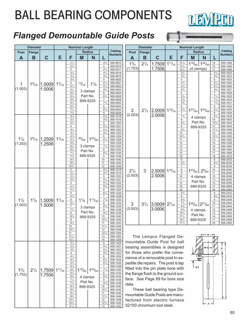
11/4 19/16 1.2509 13/1663/64 125/64
1.2506
BALL BEARING COMPONENTS
Flanged Demountable Guide Posts
85
Diameter Nominal LengthCatalog
NumbersRadiusPost Flange
A B C E F M N L
Diameter Nominal LengthCatalog
NumbersRadiusPost Flange
A B C E F M N L
The Lempco Flanged De-mountable Guide Post for ballbearing assemblies is designedfor those who prefer the conve-nience of a removable post to ex-pedite die repairs. The post is tapfitted into the pin plate bore withthe flange flush to the ground sur-face. See Page 89 for bore sizedata.
These ball bearing type De-mountable Guide Posts are manu-factured from electric furnace52100 chromium tool steel.
1 15/16 1.0009 13/1613/16 11/8
1.0006(1.003) 3 clampsPart No.
899-9225
(1.253) 3 clampsPart No.
899-9325
11/2 17/8 1.5009 17/16 11/8 117/32
1.5006(1.503) 3 clampsPart No.
899-9325
13/4 21/4 1.7509 111/16 119/64 145/64
1.7506 4 clampsPart No.
899-9325
(1.753)
13/4 21/4 1.7509 111/16 119/64 145/64
1.7506 (4 clamps)(1.753)
2 21/2 2.0009 115/16 127/64 153/64
2.0006 4 clampsPart No.
899-9325
(2.003)
21/2 3 2.5009 115/16 143/64 25/64
2.5006 4 clampsPart No.
899-9325
(2.503)
3 31/2 3.0009 27/16 159/64 221/64
3.0006 4 clampsPart No.
899-9325
(3.003)
21/2 33/4 956-0815 23/4 4 956-0816 3 41/4 956-0817 31/4 41/2 956-0818 31/2 43/4 956-0819 33/4 5 956-0820 4 51/4 956-0821 41/4 51/2 956-0822 41/2 53/4 956-0823 43/4 6 956-0824 51/4 61/2 956-0826 53/4 7 956-0828 61/4 71/2 956-0830 63/4 8 956-0832 71/4 81/2 956-0834 73/4 9 956-0836 31/4 41/2 956-1018 31/2 43/4 956-1019 33/4 5 956-1020 4 51/4 956-1021 41/4 51/2 956-1022 41/2 53/4 956-1023 43/4 6 956-1024 51/4 61/2 956-1026 53/4 7 956-1028 61/4 71/2 956-1030 63/4 8 956-1032 71/4 81/2 956-1034 73/4 9 956-1036 83/4 10 956-1040 93/4 11 956-1044103/4 12 956-1048 3 41/2 956-1218 31/4 43/4 956-1219 31/2 5 956-1220 33/4 51/4 956-1221 4 51/2 956-1222 41/4 53/4 956-1223 41/2 6 956-1224 5 61/2 956-1226 51/2 7 956-1228 6 71/2 956-1230 61/2 8 956-1232 7 81/2 956-1234 71/2 9 956-1236 8 91/2 956-1238 81/2 10 956-1240 9 101/2 956-1242 91/2 11 956-124410 111/2 956-1246101/2 12 956-124811 121/2 956-1250111/2 13 956-1252121/2 14 956-1256 31/4 5 956-1420 31/2 51/4 956-1421 33/4 51/2 956-1422 4 53/4 956-1423 41/4 6 956-1424 41/2 61/4 956-1425 43/4 61/2 956-1426 51/4 7 956-1428 53/4 71/2 956-1430 61/4 8 956-1432 63/4 81/2 956-1434 71/4 9 956-1436 73/4 91/2 956-1438 81/4 10 956-1440 83/4 101/2 956-1442 91/4 11 956-1444 93/4 111/2 956-1446101/4 12 956-1448103/4 121/2 956-1450111/4 13 956-1452
121/4 14 956-1456131/4 15 956-1460151/4 17 956-1468 31/2 51/2 956-1622 33/4 53/4 956-1623 4 6 956-1624 41/4 61/4 956-1625 41/2 61/2 956-1626 43/4 63/4 956-1627 5 7 956-1628 51/4 71/4 956-1629 51/2 71/2 956-1630 53/4 73/4 956-1631 6 8 956-1632 61/2 81/2 956-1634 7 9 956-1636 71/2 91/2 956-1638 8 10 956-1640 81/2 101/2 956-1642 9 11 956-1644 91/2 111/2 956-164610 12 956-1648101/2 121/2 956-165011 13 956-165212 14 956-165613 15 956-166014 16 956-166415 17 956-166816 18 956-1672 6 8 956-2032 61/2 81/2 956-2034 7 9 956-2036 8 10 956-2040 9 11 956-204410 12 956-204811 13 956-205212 14 956-205615 17 956-206818 20 956-2080 51/2 8 956-2432 6 81/2 956-2434 61/2 9 956-2436 71/2 10 956-2440 81/2 11 956-2444 91/2 12 956-2448101/2 13 956-2452111/2 14 956-2456141/2 17 956-2468171/2 20 956-2480
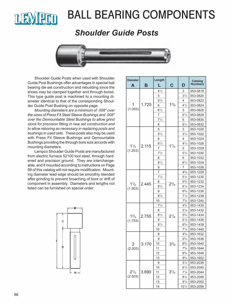
86
BALL BEARING COMPONENTSShoulder Guide Posts
Diameter Length CatalogNumbersA B L C D
1 1.725 13/8(1.003)
11/4 2.115 17/8(1.253)
11/2 2.445 23/8(1.503)
13/4 2.755 27/8(1.753)
2 3.170 33/8(2.003)
21/2 3.690 37/8(2.503)
41/2 3 953-0818 5 31/2 953-0820 51/2 4 953-0822 6 41/2 953-0824 61/2 5 953-0826 7 51/2 953-0828 71/2 6 953-0830 8 61/2 953-0832 5 3 953-1020 51/2 31/2 953-1022 6 4 953-1024 61/2 41/2 953-1026 7 5 953-1028 71/2 51/2 953-1030 8 6 953-1032 81/2 61/2 953-1034 9 7 953-1036 7 45/8 953-1228 71/2 51/8 953-1230 8 55/8 953-1232 81/2 61/8 953-1234 9 65/8 953-1236 91/2 71/8 953-123810 75/8 953-1240 71/2 45/8 953-1430 8 51/8 953-1432 81/2 55/8 953-1434 9 61/8 953-1436 91/2 65/8 953-143810 71/8 953-1440 8 45/8 953-1632 9 55/8 953-163610 65/8 953-164011 75/8 953-164412 85/8 953-164813 95/8 953-1652 9 51/8 953-203610 61/8 953-204011 71/8 953-204412 81/8 953-204813 91/8 953-205214 101/8 953-2056
Shoulder Guide Posts when used with ShoulderGuide Post Bushings offer advantages in special ballbearing die set construction and rebuilding since theshoes may be clamped together and through bored.This type guide post is machined to a mounting di-ameter identical to that of the corresponding Shoul-der Guide Post Bushing on opposite page.
Mounting diameters are a minimum of .008" overthe sizes of Press Fit Steel Sleeve Bushings and .008"over the Demountable Steel Bushings to allow grindstock for precision fitting in new set construction andto allow reboring as necessary in replacing posts andbushings in used sets. These posts also may be usedwith Press Fit Sleeve Bushings and DemountableBushings providing the through bore size accords withmounting diameters.
Lempco Shoulder Guide Posts are manufacturedfrom electric furnace 52100 tool steel, through hard-ened and precision ground. They are interchange-able, and if mounted according to instructions on Page89 of this catalog will not require modification. Mount-ing diameter lead edge should be smoothly blendedafter grinding to prevent broaching of bore or drift ofcomponent in assembly. Diameters and lengths notlisted can be furnished on special order.
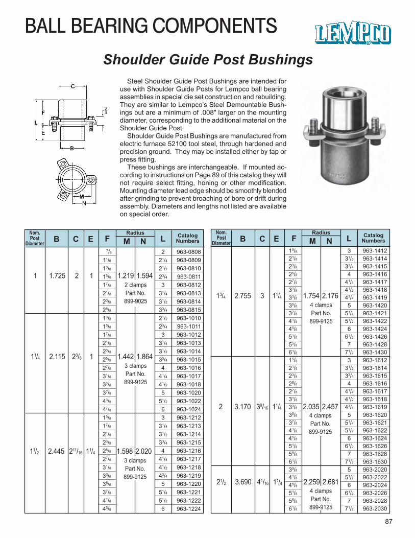
15/8 3 963-141221/8 31/2 963-141423/8 33/4 963-141525/8 4 963-141627/8 41/4 963-141731/8 41/2 963-141833/8 43/4 963-141935/8 5 963-142037/8 51/4 963-142141/8 51/2 963-142245/8 6 963-142451/8 61/2 963-142655/8 7 963-142861/8 71/2 963-143015/8 3 963-161221/8 31/2 963-161423/8 33/4 963-161525/8 4 963-161627/8 41/4 963-161731/8 41/2 963-161833/8 43/4 963-161935/8 5 963-162037/8 51/4 963-162141/8 51/2 963-162245/8 6 963-162451/8 61/2 963-162655/8 7 963-162861/8 71/2 963-163035/8 5 963-202041/8 51/2 963-202245/8 6 963-202451/8 61/2 963-202655/8 7 963-202861/8 71/2 963-2030
7/8 2 963-080811/8 21/4 963-080913/8 21/2 963-081015/8 23/4 963-081117/8 3 963-081221/8 31/4 963-081323/8 31/2 963-081425/8 33/4 963-081513/8 21/2 963-101015/8 23/4 963-101117/8 3 963-101221/8 31/4 963-101323/8 31/2 963-101425/8 33/4 963-101527/8 4 963-101631/8 41/4 963-101733/8 41/2 963-101837/8 5 963-102043/8 51/2 963-102247/8 6 963-102415/8 3 963-121217/8 31/4 963-121321/8 31/2 963-121423/8 33/4 963-121525/8 4 963-121627/8 41/4 963-121731/8 41/2 963-121833/8 43/4 963-121935/8 5 963-122037/8 51/4 963-122141/8 51/2 963-122245/8 6 963-1224
BALL BEARING COMPONENTS
87
Shoulder Guide Post Bushings
Nom.Post
Diameter B C E FRadius
M NCatalog
NumbersLNom.Post
Diameter B C E FRadius
M NCatalog
NumbersL
1 1.725 2 1 1.219 1.5942 clampsPart No.899-9025
11/4 2.115 23/8 1 1.442 1.8643 clampsPart No.899-9125
11/2 2.445 211/16 11/4 1.598 2.0203 clampsPart No.899-9125
13/4 2.755 3 11/4 1.754 2.1764 clampsPart No.899-9125
2 3.170 39/16 11/4 2.035 2.4574 clampsPart No.899-9125
21/2 3.690 41/16 11/4 2.259 2.6814 clampsPart No.899-9125
Steel Shoulder Guide Post Bushings are intended foruse with Shoulder Guide Posts for Lempco ball bearingassemblies in special die set construction and rebuilding.They are similar to Lempco’s Steel Demountable Bush-ings but are a minimum of .008" larger on the mountingdiameter, corresponding to the additional material on theShoulder Guide Post.
Shoulder Guide Post Bushings are manufactured fromelectric furnace 52100 tool steel, through hardened andprecision ground. They may be installed either by tap orpress fitting.
These bushings are interchangeable. If mounted ac-cording to instructions on Page 89 of this catalog they willnot require select fitting, honing or other modification.Mounting diameter lead edge should be smoothly blendedafter grinding to prevent broaching of bore or drift duringassembly. Diameters and lengths not listed are availableon special order.
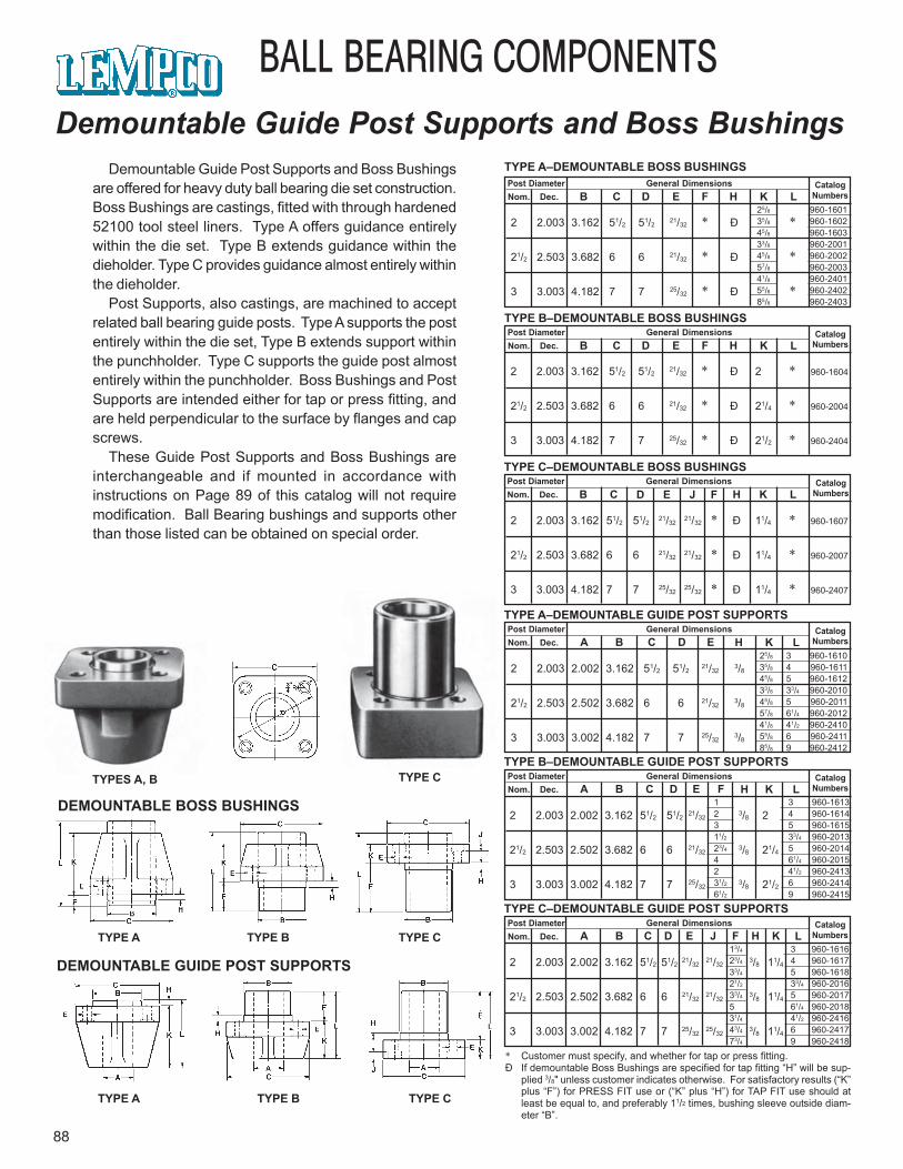
2 2.003 3.162 51/2 51/2 21/3221/32 * Ð 11/4 * 960-1607
21/2 2.503 3.682 6 6 21/3221/32 * Ð 11/4 * 960-2007
3 3.003 4.182 7 7 25/3225/32 * Ð 11/4 * 960-2407
2 2.003 2.002 3.162 51/2 51/2 21/3221/32
3/8 11/4
21/2 2.503 2.502 3.682 6 6 21/3221/32
3/8 11/4
3 3.003 3.002 4.182 7 7 25/3225/32
3/8 11/4
13/4 3 960-161623/4 4 960-161733/4 5 960-161821/2 33/4 960-201633/4 5 960-20175 61/4 960-201831/4 41/2 960-241643/4 6 960-241773/4 9 960-2418
1 3 960-16132 4 960-16143 5 960-161511/2 33/4 960-201323/4 5 960-20144 61/4 960-20152 41/2 960-241331/2 6 960-241461/2 9 960-2415
2 2.003 2.002 3.162 51/2 51/2 21/323/8 2
21/2 2.503 2.502 3.682 6 6 21/323/8 21/4
3 3.003 3.002 4.182 7 7 25/323/8 21/2
25/8 3 960-161035/8 4 960-161145/8 5 960-161233/8 33/4 960-201045/8 5 960-201157/8 61/4 960-201241/8 41/2 960-241055/8 6 960-241185/8 9 960-2412
2 2.003 2.002 3.162 51/2 51/2 21/323/8
21/2 2.503 2.502 3.682 6 6 21/323/8
3 3.003 3.002 4.182 7 7 25/323/8
2 2.003 3.162 51/2 51/2 21/32 * Ð *
21/2 2.503 3.682 6 6 21/32 * Ð *
3 3.003 4.182 7 7 25/32 * Ð *
25/8 960-160135/8 960-160245/8 960-160333/8 960-200145/8 960-200257/8 960-200341/8 960-240155/8 960-240285/8 960-2403
88
BALL BEARING COMPONENTSDemountable Guide Post Supports and Boss Bushings
Demountable Guide Post Supports and Boss Bushingsare offered for heavy duty ball bearing die set construction.Boss Bushings are castings, fitted with through hardened52100 tool steel liners. Type A offers guidance entirelywithin the die set. Type B extends guidance within thedieholder. Type C provides guidance almost entirely withinthe dieholder.
Post Supports, also castings, are machined to acceptrelated ball bearing guide posts. Type A supports the postentirely within the die set, Type B extends support withinthe punchholder. Type C supports the guide post almostentirely within the punchholder. Boss Bushings and PostSupports are intended either for tap or press fitting, andare held perpendicular to the surface by flanges and capscrews.
These Guide Post Supports and Boss Bushings areinterchangeable and if mounted in accordance withinstructions on Page 89 of this catalog will not requiremodification. Ball Bearing bushings and supports otherthan those listed can be obtained on special order.
TYPES A, B TYPE C
TYPE C
DEMOUNTABLE BOSS BUSHINGS
TYPE A TYPE B
TYPE CTYPE A TYPE B
DEMOUNTABLE GUIDE POST SUPPORTS
CatalogNumbers
Post Diameter General DimensionsNom. Dec. B C D E F H K L
TYPE A–DEMOUNTABLE BOSS BUSHINGS
CatalogNumbers
Post Diameter General DimensionsNom. Dec. B C D E F H K L
2 2.003 3.162 51/2 51/2 21/32 * Ð 2 * 960-1604
21/2 2.503 3.682 6 6 21/32 * Ð 21/4 * 960-2004
3 3.003 4.182 7 7 25/32 * Ð 21/2 * 960-2404
TYPE B–DEMOUNTABLE BOSS BUSHINGS
CatalogNumbers
Post Diameter General DimensionsNom. Dec. B C D E F H K L
TYPE C–DEMOUNTABLE BOSS BUSHINGS
CatalogNumbers
Post Diameter General DimensionsNom. Dec. B C D E H K L
TYPE A–DEMOUNTABLE GUIDE POST SUPPORTS
A
CatalogNumbers
Post Diameter General DimensionsNom. Dec. B C D E H K L
TYPE B–DEMOUNTABLE GUIDE POST SUPPORTS
A F
CatalogNumbers
Post Diameter General DimensionsNom. Dec. B C D E H K L
TYPE C–DEMOUNTABLE GUIDE POST SUPPORTS
A FJ
* Customer must specify, and whether for tap or press fitting.Ð If demountable Boss Bushings are specified for tap fitting “H” will be sup-
plied 3/8" unless customer indicates otherwise. For satisfactory results (“K”plus “F”) for PRESS FIT use or (“K” plus “H”) for TAP FIT use should atleast be equal to, and preferably 11/2 times, bushing sleeve outside diam-eter “B”.
J
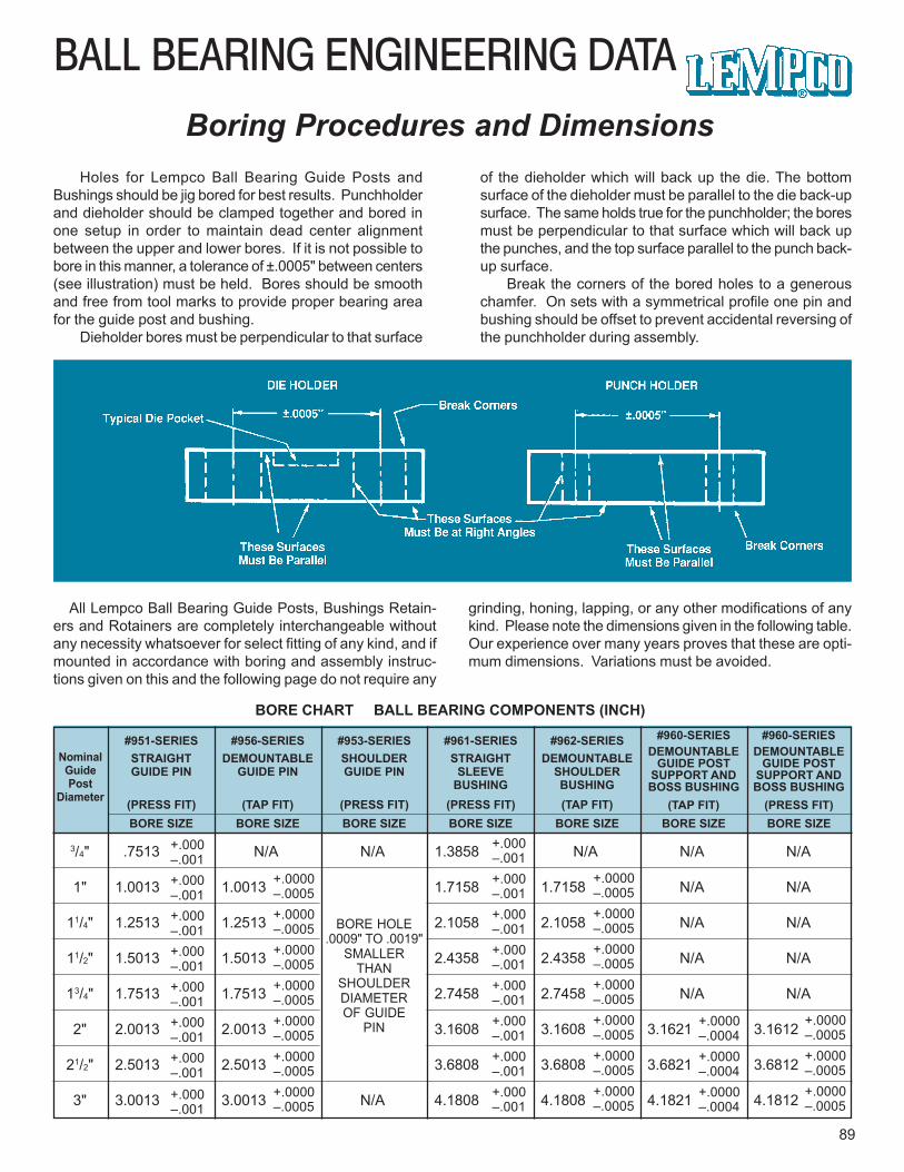
BALL BEARING ENGINEERING DATA
89
Boring Procedures and DimensionsHoles for Lempco Ball Bearing Guide Posts and
Bushings should be jig bored for best results. Punchholderand dieholder should be clamped together and bored inone setup in order to maintain dead center alignmentbetween the upper and lower bores. If it is not possible tobore in this manner, a tolerance of ±.0005" between centers(see illustration) must be held. Bores should be smoothand free from tool marks to provide proper bearing areafor the guide post and bushing.
Dieholder bores must be perpendicular to that surface
of the dieholder which will back up the die. The bottomsurface of the dieholder must be parallel to the die back-upsurface. The same holds true for the punchholder; the boresmust be perpendicular to that surface which will back upthe punches, and the top surface parallel to the punch back-up surface.
Break the corners of the bored holes to a generouschamfer. On sets with a symmetrical profile one pin andbushing should be offset to prevent accidental reversing ofthe punchholder during assembly.
All Lempco Ball Bearing Guide Posts, Bushings Retain-ers and Rotainers are completely interchangeable withoutany necessity whatsoever for select fitting of any kind, and ifmounted in accordance with boring and assembly instruc-tions given on this and the following page do not require any
grinding, honing, lapping, or any other modifications of anykind. Please note the dimensions given in the following table.Our experience over many years proves that these are opti-mum dimensions. Variations must be avoided.
BORE CHART BALL BEARING COMPONENTS (INCH)
NominalGuidePost
Diameter
#951-SERIESSTRAIGHTGUIDE PIN
(PRESS FIT)
#956-SERIESDEMOUNTABLE
GUIDE PIN
(TAP FIT)
#953-SERIESSHOULDERGUIDE PIN
(PRESS FIT)
#961-SERIESSTRAIGHT
SLEEVEBUSHING
(PRESS FIT)
#962-SERIESDEMOUNTABLE
SHOULDERBUSHING(TAP FIT)
#960-SERIESDEMOUNTABLE
GUIDE POSTSUPPORT ANDBOSS BUSHING
(TAP FIT)
#960-SERIESDEMOUNTABLE
GUIDE POSTSUPPORT ANDBOSS BUSHING
(PRESS FIT)BORE SIZE BORE SIZE BORE SIZE BORE SIZE BORE SIZE BORE SIZE BORE SIZE
3/4" .7513 N/A N/A 1.3858 N/A N/A N/A
1" 1.0013 1.0013 1.7158 1.7158 N/A N/A
11/4" 1.2513 1.2513 2.1058 2.1058 N/A N/A
11/2" 1.5013 1.5013 2.4358 2.4358 N/A N/A
13/4" 1.7513 1.7513 2.7458 2.7458 N/A N/A
2" 2.0013 2.0013 3.1608 3.1608 3.1621 3.1612
21/2" 2.5013 2.5013 3.6808 3.6808 3.6821 3.6812
3" 3.0013 3.0013 N/A 4.1808 4.1808 4.1821 4.1812
+.000–.001
+.0000–.0005
BORE HOLE.0009" TO .0019"
SMALLERTHAN
SHOULDERDIAMETEROF GUIDE
PIN
+.000–.001
+.0000–.0005
+.0000–.0004
+.0000–.0005
+.000–.001+.000–.001+.000–.001+.000–.001+.000–.001+.000–.001+.000–.001
+.0000–.0005+.0000–.0005+.0000–.0005+.0000–.0005+.0000–.0005+.0000–.0005
+.000–.001+.000–.001+.000–.001+.000–.001+.000–.001+.000–.001+.000–.001
+.0000–.0005+.0000–.0005+.0000–.0005+.0000–.0005+.0000–.0005+.0000–.0005
+.0000–.0004+.0000–.0004
+.0000–.0005+.0000–.0005

90
BALL BEARING ENGINEERING DATA
PunchShoe
SmallRadius
GuidePost
ROTAINER
Bushing
FIGURE 1 Large Radius Die Shoe
Installation and Assembly Instructions
FIGURE 2
Right Way Wrong Way Wrong Way
n order to maintain die and punchalignment it is essential that theguide posts and bushings be at
absolute right angles with the punchand die back-up surfaces.
FIGURE 1 represents a typical guidepost and ROTAINER®. Please note thatthe end of the guide post with the smallradius is press fit into the punch shoe,and that the ROTAINER® is assembledwith the ROTAINER® Slide assemblytoward the same end of the guide post.On the bushing, however, the end withthe large outside diameter radius ispress fit into the die shoe.Note: Lempco Demountable Bushingsand Flanged Demountable GuidePosts are tap fitted. Bores should beto specifications, and both bushingsand guide posts should be seated flushto ground surface of support shoe andheld securely by clamps and capscrews. These bushings and guideposts are removable; on installation thedie will register accurately.
Check the squareness of the guidepost or bushing with a precision square.Tap the sides slightly with a softhammer until the guide post or bushingis perpendicular.
Press fit about 1/4" and check with theprecision square again, tapping thesides with a soft hammer as necessary,to ensure squareness. A bronze, babbit
or fiber hammer is recommended .Note: With Demountable BossBushings be sure to press against thehardened liner and not against thecasting.
Press fit by small increments (notover 1/2" each) checking with theprecision square after each press. Donot allow guide post or bushing toprotrude through the lower side of theplate. It is advisable to place 1/64" shimunder the guide post or bushing as astop.
For Demountable Boss Bushings andDemountable Bushings – after thebushing is tap fit to the shoulder, theshoe may be drilled with the bushingin place. Tighten screws gradually,moving from one to another until allare tight.
After complete assembly of thebushings check the ID top and bottomfor taper. Should taper be found,hone the ID until original size isobtained.Note: This should not be necessaryif boring instructions were strictlyadhered to.
Assemble ROTAINER® to guide post(FIGURE 1) by screwing the setscrew in until flush with specialROTAINER® slide. Vertical androtational movement should now be
I
tested to insure freedom of movement.After testing is completed, stake setscrew. Lubricate only with light spindle oil.Note: The only tool necessary toassemble the ROTAINER® is a screwdriver.
Assemble punch and die holder. Be sureto allow ROTAINERS® to hang free (seeFIGURE 2) supported by the specialROTAINER® slide when assembling dieset. Work punch holder up and down afew times to assure there is no binding.
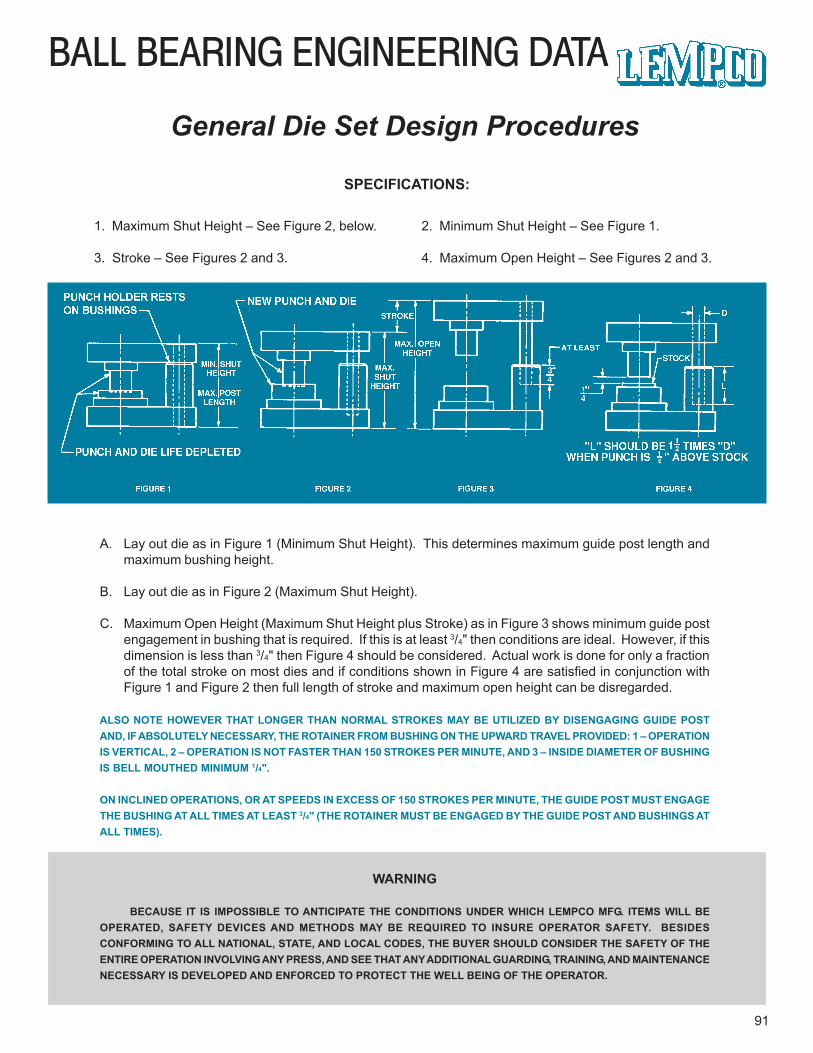
BALL BEARING ENGINEERING DATA
91
General Die Set Design Procedures
SPECIFICATIONS:
1. Maximum Shut Height – See Figure 2, below.
3. Stroke – See Figures 2 and 3.
2. Minimum Shut Height – See Figure 1.
4. Maximum Open Height – See Figures 2 and 3.
A. Lay out die as in Figure 1 (Minimum Shut Height). This determines maximum guide post length andmaximum bushing height.
B. Lay out die as in Figure 2 (Maximum Shut Height).
C. Maximum Open Height (Maximum Shut Height plus Stroke) as in Figure 3 shows minimum guide postengagement in bushing that is required. If this is at least 3/4" then conditions are ideal. However, if thisdimension is less than 3/4" then Figure 4 should be considered. Actual work is done for only a fractionof the total stroke on most dies and if conditions shown in Figure 4 are satisfied in conjunction withFigure 1 and Figure 2 then full length of stroke and maximum open height can be disregarded.
ALSO NOTE HOWEVER THAT LONGER THAN NORMAL STROKES MAY BE UTILIZED BY DISENGAGING GUIDE POSTAND, IF ABSOLUTELY NECESSARY, THE ROTAINER FROM BUSHING ON THE UPWARD TRAVEL PROVIDED: 1 – OPERATIONIS VERTICAL, 2 – OPERATION IS NOT FASTER THAN 150 STROKES PER MINUTE, AND 3 – INSIDE DIAMETER OF BUSHINGIS BELL MOUTHED MINIMUM 1/4".
ON INCLINED OPERATIONS, OR AT SPEEDS IN EXCESS OF 150 STROKES PER MINUTE, THE GUIDE POST MUST ENGAGETHE BUSHING AT ALL TIMES AT LEAST 3/4" (THE ROTAINER MUST BE ENGAGED BY THE GUIDE POST AND BUSHINGS ATALL TIMES).
WARNING
BECAUSE IT IS IMPOSSIBLE TO ANTICIPATE THE CONDITIONS UNDER WHICH LEMPCO MFG. ITEMS WILL BEOPERATED, SAFETY DEVICES AND METHODS MAY BE REQUIRED TO INSURE OPERATOR SAFETY. BESIDESCONFORMING TO ALL NATIONAL, STATE, AND LOCAL CODES, THE BUYER SHOULD CONSIDER THE SAFETY OF THEENTIRE OPERATION INVOLVING ANY PRESS, AND SEE THAT ANY ADDITIONAL GUARDING, TRAINING, AND MAINTENANCENECESSARY IS DEVELOPED AND ENFORCED TO PROTECT THE WELL BEING OF THE OPERATOR.
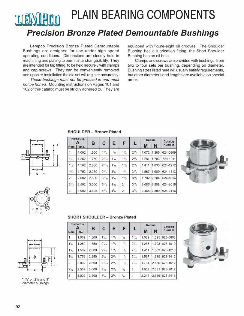
92
PLAIN BEARING COMPONENTSPrecision Bronze Plated Demountable Bushings
Lempco Precision Bronze Plated DemountableBushings are designed for use under high speedoperating conditions. Dimensions are closely held inmachining and plating to permit interchangeability. Theyare intended for tap fitting, to be held securely with clampsand cap screws. They can be conveniently removedand upon re-installation the die set will register accurately.
These bushings must not be pressed in and mustnot be honed. Mounting instructions on Pages 101 and102 of this catalog must be strictly adhered to. They are
*11/4" on 21/2 and 3"diameter bushings
equipped with figure-eight oil grooves. The ShoulderBushing has a lubrication fitting, the Short ShoulderBushing has an oil hole.
Clamps and screws are provided with bushings, fromtwo to four sets per bushing, depending on diameter.Bushing sizes listed here will usually satisfy requirements,but other diameters and lengths are available on specialorder.
Inside Dia.A
Nom. Dec.
Radius CatalogNumberB C E F L M N
1 1.002 1.500 13/47/8 11/4 21/8 1.072 1.385 624-0809
11/4 1.252 1.750 21/16 11/8 11/2 25/8 1.281 1.703 624-1011
11/2 1.502 2.000 25/16 13/8 11/2 27/8 1.411 1.833 624-1212
13/4 1.752 2.250 25/8 15/8 11/2 31/8 1.567 1.989 624-1413
2 2.002 2.500 31/32 17/8 11/2 33/8 1.782 2.204 624-1614
21/2 2.502 3.000 35/8 17/8 2 37/8 2.086 2.508 624-2016
3 3.002 3.625 43/8 17/8 2 37/8 2.468 2.889 624-2416
SHOULDER – Bronze Plated
Inside Dia.A
Nom. Dec.
Radius CatalogNumberB C E F L M N
SHORT SHOULDER – Bronze Plated
1 1.002 1.500 13/4 13/8 1/2 17/8 1.082 1.395 623-0808
11/4 1.252 1.750 21/16 17/8 1/2 23/8 1.286 1.708 623-1010
11/2 1.502 2.000 25/16 17/8 1/2 23/8 1.411 1.833 623-1210
13/4 1.752 2.250 25/8 23/8 1/2 27/8 1.567 1.989 623-1412
2 2.002 2.500 215/16 23/8 1/2 27/8 1.734 2.156 623-1612
21/2 2.502 3.000 33/8 25/8 3/8 3 1.959 2.381 623-2012
3 3.002 3.500 37/8 35/8 3/8 4 2.214 2.636 623-2416
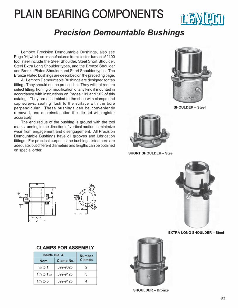
PLAIN BEARING COMPONENTS
93
Precision Demountable Bushings
Lempco Precision Demountable Bushings, also seePage 94, which are manufactured from electric furnace 52100tool steel include the Steel Shoulder, Steel Short Shoulder,Steel Extra Long Shoulder types, and the Bronze Shoulderand Bronze Plated Shoulder and Short Shoulder types. TheBronze Plated bushings are described on the preceding page.
All Lempco Demountable Bushings are designed for tapfitting. They should not be pressed in. They will not requireselect fitting, honing or modification of any kind if mounted inaccordance with instructions on Pages 101 and 102 of thiscatalog. They are assembled to the shoe with clamps andcap screws, seating flush to the surface with the boreperpendicular. These bushings can be convenientlyremoved, and on reinstallation the die set will registeraccurately.
The end radius of the bushing is ground with the toolmarks running in the direction of vertical motion to minimizewear from engagement and disengagement. All PrecisionDemountable Bushings have oil grooves and lubricationfittings. For practical purposes the bushings listed here areadequate, but different diameters and lengths can be obtainedon special order.
SHOULDER – Steel
SHORT SHOULDER – Steel
SHOULDER – Bronze
Inside Dia. ANom. Clamp No.
NumberClamps
1/2 to 1 899-9025 2
11/4 to 11/2` 899-9125 3
13/4 to 3 899-9125 4
CLAMPS FOR ASSEMBLY
EXTRA LONG SHOULDER – Steel
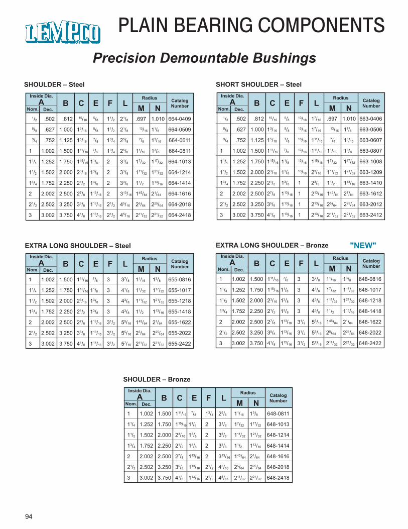
1/2 .502 .812 15/16 5/8 11/2 21/8 .697 1.010 664-0409
5/8 .627 1.000 13/16 5/8 11/2 21/8 13/16 11/8 664-0509
3/4 .752 1.125 15/16 7/8 13/4 25/8 7/8 13/16 664-0611
1 1.002 1.500 111/16 7/8 13/4 25/8 11/16 13/8 664-0811
11/4 1.252 1.750 115/16 11/8 2 31/8 17/32 117/32 664-1013
11/2 1.502 2.000 23/16 13/8 2 33/8 111/32 121/32 664-1214
13/4 1.752 2.250 21/2 13/8 2 33/8 11/2 113/16 664-1414
2 2.002 2.500 27/8 113/16 2 313/16 145/64 21/64 664-1616
21/2 2.502 3.250 35/8 113/16 21/2 45/16 25/64 225/64 664-2018
3 3.002 3.750 41/8 113/16 21/2 45/16 211/32 221/32 664-2418
94
PLAIN BEARING COMPONENTSPrecision Demountable Bushings
Inside Dia.A
Nom. Dec.
Radius CatalogNumberB C E F L M N
SHOULDER – Steel
1/2 .502 .812 15/16 5/8 13/16 17/16 .697 1.010 663-0406
5/8 .627 1.000 13/16 5/8 13/16 17/16 13/16 11/8 663-0506
3/4 .752 1.125 15/16 7/8 13/16 111/16 7/8 13/16 663-0607
1 1.002 1.500 111/16 7/8 13/16 111/16 11/16 13/8 663-0807
11/4 1.252 1.750 115/16 11/8 13/16 115/16 17/32 117/32 663-1008
11/2 1.502 2.000 23/16 13/813/16 23/16 111/32 121/32 663-1209
13/4 1.752 2.250 21/2 13/8 1 23/8 11/2 113/16 663-1410
2 2.002 2.500 27/8 113/16 1 213/16 145/64 21/64 663-1612
21/2 2.502 3.250 35/8 113/16 1 213/16 25/64 225/64 663-2012
3 3.002 3.750 41/8 113/16 1 213/16 211/32 221/32 663-2412
Inside Dia.A
Nom. Dec.
Radius CatalogNumberB C E F L M N
SHORT SHOULDER – Steel
1 1.002 1.500 111/16 7/8 3 37/8 11/16 13/8 655-0816
11/4 1.252 1.750 115/16 11/8 3 41/8 17/32 117/32 655-1017
11/2 1.502 2.000 23/16 13/8 3 43/8 111/32 121/32 655-1218
13/4 1.752 2.250 21/2 13/8 3 43/8 11/2 113/16 655-1418
2 2.002 2.500 27/8 113/16 31/2 55/16 145/64 21/64 655-1622
21/2 2.502 3.250 35/8 113/16 31/2 55/16 25/64 225/64 655-2022
3 3.002 3.750 41/8 115/16 31/2 57/16 211/32 221/32 655-2422
Inside Dia.A
Nom. Dec.
Radius CatalogNumberB C E F L M N
EXTRA LONG SHOULDER – Steel
1 1.002 1.500 111/16 7/8 3 37/8 11/16 13/8 648-0816
11/4 1.252 1.750 115/16 11/8 3 41/8 17/32 117/32 648-1017
11/2 1.502 2.000 23/16 13/8 3 43/8 111/32 121/32 648-1218
13/4 1.752 2.250 21/2 13/8 3 43/8 11/2 113/16 648-1418
2 2.002 2.500 27/8 113/16 31/2 55/16 145/64 21/64 648-1622
21/2 2.502 3.250 35/8 113/16 31/2 55/16 25/64 225/64 648-2022
3 3.002 3.750 41/8 115/16 31/2 57/16 211/32 221/32 648-2422
Inside Dia.A
Nom. Dec.
Radius CatalogNumberB C E F L M N
EXTRA LONG SHOULDER – Bronze
1 1.002 1.500 111/16 7/8 13/4 25/8 11/16 13/8 648-0811
11/4 1.252 1.750 115/16 11/8 2 31/8 17/32 117/32 648-1013
11/2 1.502 2.000 23/16 13/8 2 33/8 111/32 121/32 648-1214
13/4 1.752 2.250 21/2 13/8 2 33/8 11/2 113/16 648-1414
2 2.002 2.500 27/8 113/16 2 313/16 145/64 21/64 648-1616
21/2 2.502 3.250 35/8 113/16 21/2 45/16 25/64 225/64 648-2018
3 3.002 3.750 41/8 113/16 21/2 45/16 211/32 221/32 648-2418
Inside Dia.A
Nom. Dec.
Radius CatalogNumberB C E F L M N
SHOULDER – Bronze
"NEW"
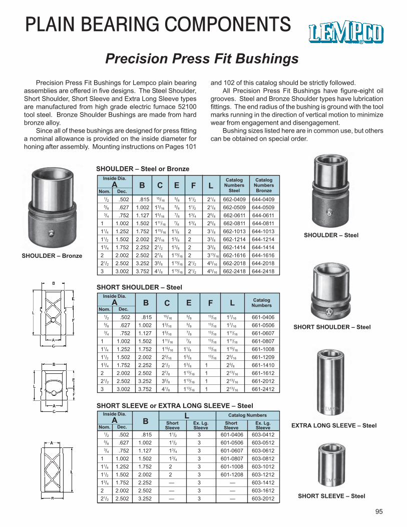
PLAIN BEARING COMPONENTS
95
Precision Press Fit BushingsPrecision Press Fit Bushings for Lempco plain bearing
assemblies are offered in five designs. The Steel Shoulder,Short Shoulder, Short Sleeve and Extra Long Sleeve typesare manufactured from high grade electric furnace 52100tool steel. Bronze Shoulder Bushings are made from hardbronze alloy.
Since all of these bushings are designed for press fittinga nominal allowance is provided on the inside diameter forhoning after assembly. Mounting instructions on Pages 101
SHOULDER – Steel
SHORT SHOULDER – Steel
SHORT SLEEVE – Steel
EXTRA LONG SLEEVE – Steel
and 102 of this catalog should be strictly followed.All Precision Press Fit Bushings have figure-eight oil
grooves. Steel and Bronze Shoulder types have lubricationfittings. The end radius of the bushing is ground with the toolmarks running in the direction of vertical motion to minimizewear from engagement and disengagement.
Bushing sizes listed here are in common use, but otherscan be obtained on special order.
1/2 .502 .815 15/16 5/8 11/2 21/8 662-0409 644-0409 5/8 .627 1.002 13/16 5/8 11/2 21/8 662-0509 644-0509 3/4 .752 1.127 15/16 7/8 13/4 25/8 662-0611 644-06111 1.002 1.502 111/16
7/8 13/4 25/8 662-0811 644-081111/4 1.252 1.752 115/16 11/8 2 31/8 662-1013 644-101311/2 1.502 2.002 23/16 13/8 2 33/8 662-1214 644-121413/4 1.752 2.252 21/2 13/8 2 33/8 662-1414 644-14142 2.002 2.502 27/8 113/16 2 313/16 662-1616 644-161621/2 2.502 3.252 35/8 113/16 21/2 45/16 662-2018 644-20183 3.002 3.752 41/8 113/16 21/2 45/16 662-2418 644-2418
Inside Dia.A
Nom. Dec.
CatalogNumbersBronze
B C E F L
SHOULDER – Steel or BronzeCatalog
NumbersSteel
1/2 .502 .815 15/16 5/8 13/16 17/16 661-0406 5/8 .627 1.002 13/16 5/8 13/16 17/16 661-0506 3/4 .752 1.127 15/16 7/8 13/16 111/16 661-06071 1.002 1.502 111/16
7/8 13/16 111/16 661-080711/4 1.252 1.752 115/16 11/8 13/16 115/16 661-100811/2 1.502 2.002 23/16 13/8 13/16 23/16 661-120913/4 1.752 2.252 21/2 13/8 1 23/8 661-14102 2.002 2.502 27/8 113/16 1 213/16 661-161221/2 2.502 3.252 35/8 113/16 1 213/16 661-20123 3.002 3.752 41/8 113/16 1 213/16 661-2412
Inside Dia.A
Nom. Dec.B C E F L
SHORT SHOULDER – Steel
CatalogNumbers
1/2 .502 .815 11/2 3 601-0406 603-0412 5/8 .627 1.002 11/2 3 601-0506 603-0512 3/4 .752 1.127 13/4 3 601-0607 603-06121 1.002 1.502 13/4 3 601-0807 603-081211/4 1.252 1.752 2 3 601-1008 603-101211/2 1.502 2.002 2 3 601-1208 603-121213/4 1.752 2.252 — 3 — 603-14122 2.002 2.502 — 3 — 603-161221/2 2.502 3.252 — 3 — 603-2012
Inside Dia.A
Nom. Dec.ShortSleeve
BL
SHORT SLEEVE or EXTRA LONG SLEEVE – SteelCatalog Numbers
Ex. Lg.Sleeve
ShortSleeve
Ex. Lg.Sleeve
SHOULDER – Bronze
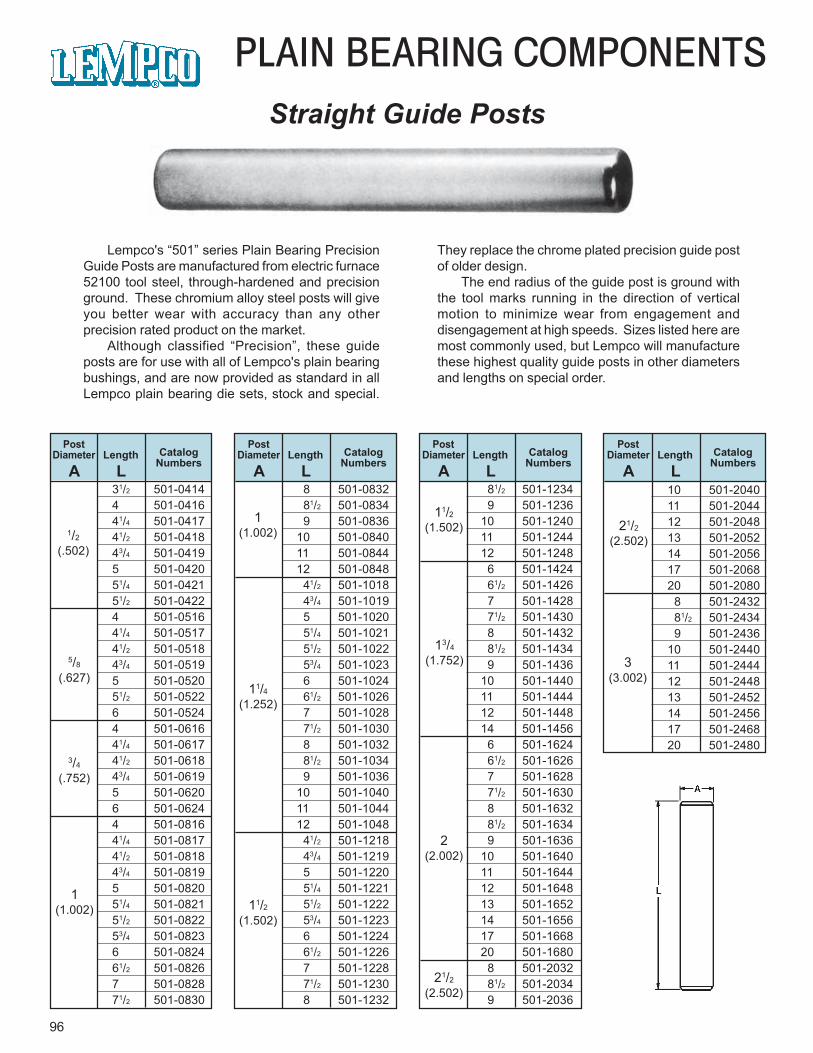
96
PLAIN BEARING COMPONENTSStraight Guide Posts
Lempco's “501” series Plain Bearing PrecisionGuide Posts are manufactured from electric furnace52100 tool steel, through-hardened and precisionground. These chromium alloy steel posts will giveyou better wear with accuracy than any otherprecision rated product on the market.
Although classified “Precision”, these guideposts are for use with all of Lempco's plain bearingbushings, and are now provided as standard in allLempco plain bearing die sets, stock and special.
They replace the chrome plated precision guide postof older design.
The end radius of the guide post is ground withthe tool marks running in the direction of verticalmotion to minimize wear from engagement anddisengagement at high speeds. Sizes listed here aremost commonly used, but Lempco will manufacturethese highest quality guide posts in other diametersand lengths on special order.
PostDiameter Length Catalog
NumbersA L
PostDiameter Length Catalog
NumbersA L
PostDiameter Length Catalog
NumbersA L
PostDiameter Length Catalog
NumbersA L
1/2
(.502)
5/8
(.627)
3/4
(.752)
1(1.002)
1(1.002)
11/4(1.252)
11/2(1.502)
11/2(1.502)
13/4
(1.752)
2(2.002)
21/2
(2.502)
21/2
(2.502)
3(3.002)
31/2 501-04144 501-041641/4 501-041741/2 501-041843/4 501-04195 501-042051/4 501-042151/2 501-04224 501-051641/4 501-051741/2 501-051843/4 501-05195 501-052051/2 501-05226 501-05244 501-061641/4 501-061741/2 501-061843/4 501-06195 501-06206 501-06244 501-081641/4 501-081741/2 501-081843/4 501-08195 501-082051/4 501-082151/2 501-082253/4 501-08236 501-082461/2 501-08267 501-082871/2 501-0830
8 501-0832 81/2 501-0834 9 501-083610 501-084011 501-084412 501-0848 41/2 501-1018 43/4 501-1019 5 501-1020 51/4 501-1021 51/2 501-1022 53/4 501-1023 6 501-1024 61/2 501-1026 7 501-1028 71/2 501-1030 8 501-1032 81/2 501-1034 9 501-103610 501-104011 501-104412 501-1048 41/2 501-1218 43/4 501-1219 5 501-1220 51/4 501-1221 51/2 501-1222 53/4 501-1223 6 501-1224 61/2 501-1226 7 501-1228 71/2 501-1230 8 501-1232
81/2 501-1234 9 501-123610 501-124011 501-124412 501-1248 6 501-1424 61/2 501-1426 7 501-1428 71/2 501-1430 8 501-1432 81/2 501-1434 9 501-143610 501-144011 501-144412 501-144814 501-1456 6 501-1624 61/2 501-1626 7 501-1628 71/2 501-1630 8 501-1632 81/2 501-1634 9 501-163610 501-164011 501-164412 501-164813 501-165214 501-165617 501-166820 501-1680 8 501-2032 81/2 501-2034 9 501-2036
10 501-204011 501-204412 501-204813 501-205214 501-205617 501-206820 501-2080 8 501-2432 81/2 501-2434 9 501-243610 501-244011 501-244412 501-244813 501-245214 501-245617 501-246820 501-2480
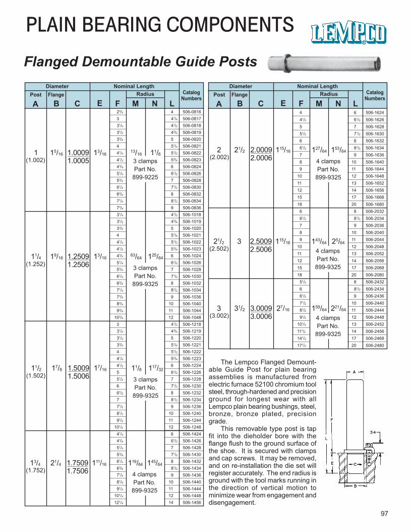
4 6 506-1624 41/2 61/2 506-1626 5 7 506-1628 51/2 71/2 506-1630 6 8 506-1632 61/2 81/2 506-1634 7 9 506-1636 8 10 506-1640 9 11 506-164410 12 506-164811 13 506-165212 14 506-165615 17 506-166818 20 506-1680 6 8 506-2032 61/2 81/2 506-2034 7 9 506-2036 8 10 506-2040 9 11 506-204410 12 506-204811 13 506-205212 14 506-205615 17 506-206818 20 506-2080 51/2 8 506-2432 6 81/2 506-2434 61/2 9 506-2436 71/2 10 506-2440 81/2 11 506-2444 91/2 12 506-2448101/2 13 506-2452111/2 14 506-2456141/2 17 506-2468171/2 20 506-2480
23/4 4 506-0816 3 41/4 506-0817 31/4 41/2 506-0818 31/2 43/4 506-0819 33/4 5 506-0820 4 51/4 506-0821 41/4 51/2 506-0822 41/2 53/4 506-0823 43/4 6 506-0824 51/4 61/2 506-0826 53/4 7 506-0828 61/4 71/2 506-0830 63/4 8 506-0832 71/4 81/2 506-0834 73/4 9 506-0836 31/4 41/2 506-1018 31/2 43/4 506-1019 33/4 5 506-1020 4 51/4 506-1021 41/4 51/2 506-1022 41/2 53/4 506-1023 43/4 6 506-1024 51/4 61/2 506-1026 53/4 7 506-1028 61/4 71/2 506-1030 63/4 8 506-1032 71/4 81/2 506-1034 73/4 9 506-1036 83/4 10 506-1040 93/4 11 506-1044103/4 12 506-1048 3 41/2 506-1218 31/4 43/4 506-1219 31/2 5 506-1220 33/4 51/4 506-1221 4 51/2 506-1222 41/4 53/4 506-1223 41/2 6 506-1224 5 61/2 506-1226 51/2 7 506-1228 6 71/2 506-1230 61/2 8 506-1232 7 81/2 506-1234 71/2 9 506-1236 81/2 10 506-1240 91/2 11 506-1244101/2 12 506-1248 41/4 6 506-1424 43/4 61/2 506-1426 51/4 7 506-1428 53/4 71/2 506-1430 61/4 8 506-1432 63/4 81/2 506-1434 71/4 9 506-1436 81/4 10 506-1440 91/4 11 506-1444101/4 12 506-1448121/4 14 506-1456
PLAIN BEARING COMPONENTS
97
Flanged Demountable Guide Posts
11/4 19/16 1.2509 13/1663/64 125/64
1.2506
Diameter Nominal LengthCatalog
NumbersRadiusPost Flange
A B C E F M N L
Diameter Nominal LengthCatalog
NumbersRadiusPost Flange
A B C E F M N L
The Lempco Flanged Demount-able Guide Post for plain bearingassemblies is manufactured fromelectric furnace 52100 chromium toolsteel, through-hardened and precisionground for longest wear with allLempco plain bearing bushings, steel,bronze, bronze plated, precisiongrade.
This removable type post is tapfit into the dieholder bore with theflange flush to the ground surface ofthe shoe. It is secured with clampsand cap screws. It may be removed,and on re-installation the die set willregister accurately. The end radius isground with the tool marks running inthe direction of vertical motion tominimize wear from engagement anddisengagement.
1 15/16 1.0009 13/1613/16 11/8
1.0005(1.002) 3 clampsPart No.
899-9225
(1.252) 3 clampsPart No.
899-9325
11/2 17/8 1.5009 17/16 11/8 117/32
1.5006(1.502) 3 clampsPart No.
899-9325
13/4 21/4 1.7509 111/16 119/64 145/64
1.7506 4 clampsPart No.
899-9325
(1.752)
2 21/2 2.0009 115/16 127/64 153/64
2.0006 4 clampsPart No.
899-9325
(2.002)
21/2 3 2.5009 115/16 143/64 25/64
2.5006 4 clampsPart No.
899-9325
(2.502)
3 31/2 3.0009 27/16 159/64 221/64
3.0006 4 clampsPart No.
899-9325
(3.002)
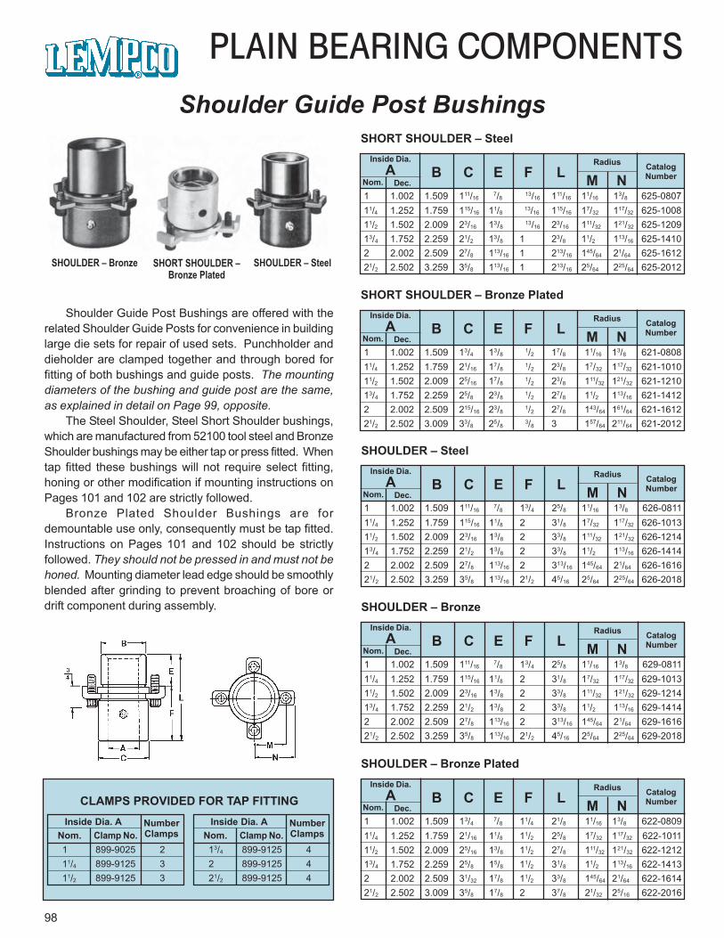
1 1.002 1.509 111/16 7/8 13/16 111/16 11/16 13/8 625-0807
11/4 1.252 1.759 115/16 11/8 13/16 115/16 17/32 117/32 625-100811/2 1.502 2.009 23/16 13/8 13/16 23/16 111/32 121/32 625-120913/4 1.752 2.259 21/2 13/8 1 23/8 11/2 113/16 625-14102 2.002 2.509 27/8 113/16 1 213/16 145/64 21/64 625-161221/2 2.502 3.259 35/8 113/16 1 213/16 25/64 225/64 625-2012
98
PLAIN BEARING COMPONENTSShoulder Guide Post Bushings
Inside Dia.A
Nom. Dec.
Radius CatalogNumberB C E F L M N
SHORT SHOULDER – Steel
1 1.002 1.509 13/4 13/8 1/2 17/8 11/16 13/8 621-080811/4 1.252 1.759 21/16 17/8 1/2 23/8 17/32 117/32 621-101011/2 1.502 2.009 25/16 17/8 1/2 23/8 111/32 121/32 621-121013/4 1.752 2.259 25/8 23/8 1/2 27/8 11/2 113/16 621-14122 2.002 2.509 215/16 23/8 1/2 27/8 143/64 161/64 621-161221/2 2.502 3.009 33/8 25/8 3/8 3 157/64 211/64 621-2012
Inside Dia.A
Nom. Dec.
Radius CatalogNumberB C E F L M N
SHORT SHOULDER – Bronze Plated
1 1.002 1.509 111/16 7/8 13/4 25/8 11/16 13/8 626-0811
11/4 1.252 1.759 115/16 11/8 2 31/8 17/32 117/32 626-101311/2 1.502 2.009 23/16 13/8 2 33/8 111/32 121/32 626-121413/4 1.752 2.259 21/2 13/8 2 33/8 11/2 113/16 626-14142 2.002 2.509 27/8 113/16 2 313/16 145/64 21/64 626-161621/2 2.502 3.259 35/8 113/16 21/2 45/16 25/64 225/64 626-2018
Inside Dia.A
Nom. Dec.
Radius CatalogNumberB C E F L M N
SHOULDER – Steel
1 1.002 1.509 13/4 7/8 11/4 21/8 11/16 13/8 622-0809
11/4 1.252 1.759 21/16 11/8 11/2 25/8 17/32 117/32 622-101111/2 1.502 2.009 25/16 13/8 11/2 27/8 111/32 121/32 622-121213/4 1.752 2.259 25/8 15/8 11/2 31/8 11/2 113/16 622-14132 2.002 2.509 31/32 17/8 11/2 33/8 145/64 21/64 622-161421/2 2.502 3.009 35/8 17/8 2 37/8 21/32 25/16 622-2016
Inside Dia.A
Nom. Dec.
Radius CatalogNumberB C E F L M N
SHOULDER – Bronze Plated
1 1.002 1.509 111/16 7/8 13/4 25/8 11/16 13/8 629-0811
11/4 1.252 1.759 115/16 11/8 2 31/8 17/32 117/32 629-101311/2 1.502 2.009 23/16 13/8 2 33/8 111/32 121/32 629-121413/4 1.752 2.259 21/2 13/8 2 33/8 11/2 113/16 629-14142 2.002 2.509 27/8 113/16 2 313/16 145/64 21/64 629-161621/2 2.502 3.259 35/8 113/16 21/2 45/16 25/64 225/64 629-2018
Inside Dia.A
Nom. Dec.
Radius CatalogNumberB C E F L M N
SHOULDER – Bronze
Inside Dia. ANom. Clamp No.
NumberClamps
Inside Dia. ANom. Clamp No.
NumberClamps
1 899-9025 211/4 899-9125 311/2 899-9125 3
13/4 899-9125 42 899-9125 421/2 899-9125 4
CLAMPS PROVIDED FOR TAP FITTING
SHOULDER – Bronze SHORT SHOULDER –Bronze Plated
SHOULDER – Steel
Shoulder Guide Post Bushings are offered with therelated Shoulder Guide Posts for convenience in buildinglarge die sets for repair of used sets. Punchholder anddieholder are clamped together and through bored forfitting of both bushings and guide posts. The mountingdiameters of the bushing and guide post are the same,as explained in detail on Page 99, opposite.
The Steel Shoulder, Steel Short Shoulder bushings,which are manufactured from 52100 tool steel and BronzeShoulder bushings may be either tap or press fitted. Whentap fitted these bushings will not require select fitting,honing or other modification if mounting instructions onPages 101 and 102 are strictly followed.
Bronze Plated Shoulder Bushings are fordemountable use only, consequently must be tap fitted.Instructions on Pages 101 and 102 should be strictlyfollowed. They should not be pressed in and must not behoned. Mounting diameter lead edge should be smoothlyblended after grinding to prevent broaching of bore ordrift component during assembly.
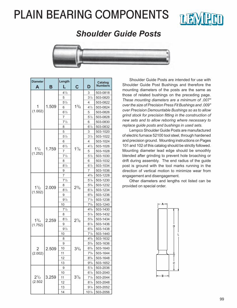
PLAIN BEARING COMPONENTS
99
Diameter Length CatalogNumbersA B L C D
1 1.509 13/8(1.002)
11/4 1.759 17/8(1.252)
11/2 2.009 23/8(1.502)
13/4 2.259 27/8(1.752)
2 2.509 33/8(2.002)
21/2 3.259 37/8(2.502
41/2 3 503-0818 5 31/2 503-0820 51/2 4 503-0822 6 41/2 503-0824 61/2 5 503-0826 7 51/2 503-0828 71/2 6 503-0830 8 61/2 503-0832 5 3 503-1020 51/2 31/2 503-1022 6 4 503-1024 61/2 41/2 503-1026 7 5 503-1028 71/2 51/2 503-1030 8 6 503-1032 81/2 61/2 503-1034 9 7 503-1036 7 45/8 503-1228 71/2 51/8 503-1230 8 55/8 503-1232 81/2 61/8 503-1234 9 65/8 503-1236 91/2 71/8 503-123810 75/8 503-1240 71/2 45/8 503-1430 8 51/8 503-1432 81/2 55/8 503-1434 9 61/8 503-1436 91/2 65/8 503-143810 71/8 503-1440 8 45/8 503-1632 9 55/8 503-163610 65/8 503-164011 75/8 503-164412 85/8 503-164813 95/8 503-1652 9 51/8 503-203610 61/8 503-204011 71/8 503-204412 81/8 503-204813 91/8 503-205214 101/8 503-2056
Shoulder Guide Posts are intended for use withShoulder Guide Post Bushings and therefore themounting diameters of the posts are the same asthose of related bushings on the preceding page.These mounting diameters are a minimum of .007"over the size of Precision Press Fit Bushings and .009"over Precision Demountable Bushings so as to allowgrind stock for precision fitting in the construction ofnew sets and to allow reboring where necessary toreplace guide posts and bushings in used sets.
Lempco Shoulder Guide Posts are manufacturedof electric furnace 52100 tool steel, through hardenedand precision ground. Mounting instructions on Pages101 and 102 of this catalog should be strictly followed.Mounting diameter lead edge should be smoothlyblended after grinding to prevent hole broaching ordrift during assembly. The end radius of the guidepost is ground with the tool marks running in thedirection of vertical motion to minimize wear fromengagement and disengagement.
Other diameters and lengths not listed can beprovided on special order.
Shoulder Guide Posts
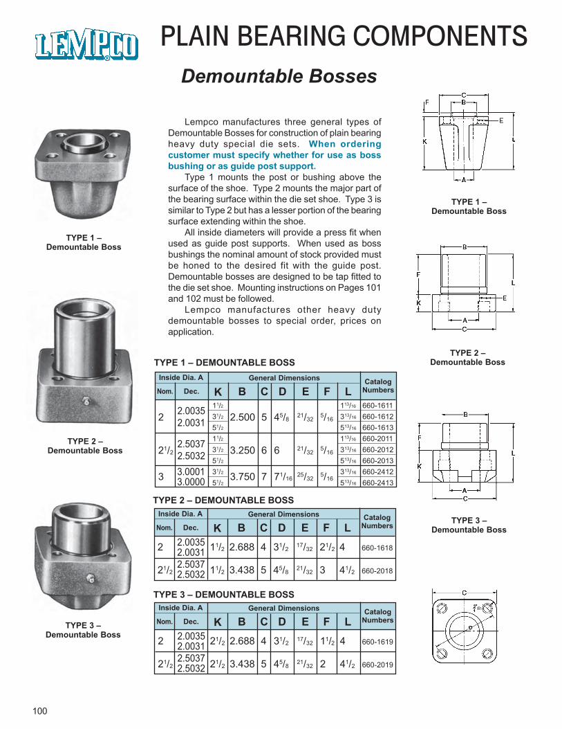
100
PLAIN BEARING COMPONENTSDemountable Bosses
TYPE 1 –Demountable Boss
TYPE 2 –Demountable Boss
TYPE 3 –Demountable Boss
TYPE 1 –Demountable Boss
TYPE 2 –Demountable Boss
TYPE 3 –Demountable Boss
Inside Dia. A General Dimensions CatalogNumbersNom. Dec. K B C D E F L
2 2.500 5 45/821/32
5/162.00352.0031
21/2 3.250 6 6 21/325/16
2.50372.5032
3 3.750 7 71/1625/32
5/163.00013.0000
11/2 113/16 660-161131/2 313/16 660-161251/2 513/16 660-161311/2 113/16 660-201131/2 313/16 660-201251/2 513/16 660-201331/2 313/16 660-241251/2 513/16 660-2413
TYPE 1 – DEMOUNTABLE BOSS
Inside Dia. A General Dimensions
Nom. Dec. K B C D E F L2 11/2 2.688 4 31/2
17/32 21/2 4 660-1618
21/2 11/2 3.438 5 45/821/32 3 41/2 660-2018
TYPE 2 – DEMOUNTABLE BOSS
2.00352.00312.50372.5032
Inside Dia. A General Dimensions CatalogNumbersNom. Dec. K B C D E F L
2 21/2 2.688 4 31/217/32 11/2 4 660-1619
21/2 21/2 3.438 5 45/821/32 2 41/2 660-2019
TYPE 3 – DEMOUNTABLE BOSS
2.00352.00312.50372.5032
Lempco manufactures three general types ofDemountable Bosses for construction of plain bearingheavy duty special die sets. When orderingcustomer must specify whether for use as bossbushing or as guide post support.
Type 1 mounts the post or bushing above thesurface of the shoe. Type 2 mounts the major part ofthe bearing surface within the die set shoe. Type 3 issimilar to Type 2 but has a lesser portion of the bearingsurface extending within the shoe.
All inside diameters will provide a press fit whenused as guide post supports. When used as bossbushings the nominal amount of stock provided mustbe honed to the desired fit with the guide post.Demountable bosses are designed to be tap fitted tothe die set shoe. Mounting instructions on Pages 101and 102 must be followed.
Lempco manufactures other heavy dutydemountable bosses to special order, prices onapplication.
CatalogNumbers
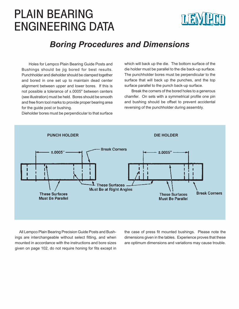
PLAIN BEARINGENGINEERING DATA
Boring Procedures and Dimensions
Holes for Lempco Plain Bearing Guide Posts andBushings should be jig bored for best results.Punchholder and dieholder should be clamped togetherand bored in one set up to maintain dead centeralignment between upper and lower bores. If this isnot possible a tolerance of ±.0005" between centers(see illustration) must be held. Bores should be smoothand free from tool marks to provide proper bearing areafor the guide post or bushing.Dieholder bores must be perpendicular to that surface
All Lempco Plain Bearing Precision Guide Posts and Bush-ings are interchangeable without select fitting, and whenmounted in accordance with the instructions and bore sizesgiven on page 102, do not require honing for fits except in
the case of press fit mounted bushings. Please note thedimensions given in the tables. Experience proves that theseare optimum dimensions and variations may cause trouble.
which will back up the die. The bottom surface of thedie holder must be parallel to the die back-up surface.The punchholder bores must be perpendicular to thesurface that will back up the punches, and the topsurface parallel to the punch back-up surface.
Break the corners of the bored holes to a generouschamfer. On sets with a symmetrical profile one pinand bushing should be offset to prevent accidentalreversing of the punchholder during assembly.
PUNCH HOLDER DIE HOLDER
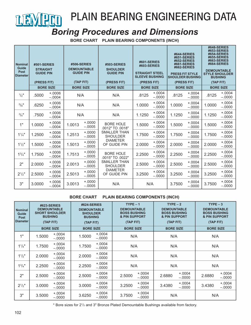
1/2" .5000 N/A N/A .8125 .8125 .8125
5/8" .6250 N/A N/A 1.0000 1.0000 1.0000
3/4" .7500 N/A N/A 1.1250 1.1250 1.1250
1" 1.0000 1.0013 1.5000 1.5000 1.5000
11/4" 1.2500 1.2513 1.7500 1.7500 1.7500
11/2" 1.5000 1.5013 2.0000 2.0000 2.0000
13/4" 1.7500 1.7513 2.2500 2.2500 2.2500
2" 2.0000 2.0013 2.5000 2.5000 2.5000
21/2" 2.5000 2.5013 3.2500 3.2500 3.2500
3" 3.0000 3.0013 N/A N/A 3.7500 3.7500
102
PLAIN BEARING ENGINEERING DATABoring Procedures and Dimensions
BORE CHART PLAIN BEARING COMPONENTS (INCH)
NominalGuidePost
Diameter
#501-SERIESSTRAIGHTGUIDE PIN
(PRESS FIT)
#506-SERIESDEMOUNTABLE
GUIDE PIN
(TAP FIT)
#503-SERIESSHOULDERGUIDE PIN
(PRESS FIT)
#601-SERIES#603-SERIES
STRAIGHT STEELSLEEVE BUSHING
(PRESS FIT)
#644-SERIES#651-SERIES#652-SERIES#661-SERIES#662-SERIES
PRESS FIT STYLESHOULDER BUSHING
(PRESS FIT)
#648-SERIES#653-SERIES#654-SERIES#655-SERIES#663-SERIES#664-SERIES
DEMOUNTABLESTYLE SHOULDER
BUSHING(TAP FIT)
BORE SIZE BORE SIZE BORE SIZE BORE SIZE BORE SIZE BORE SIZE
BORE HOLE.0012" TO .0018"SMALLER THAN
SHOULDERDIAMETER
OF GUIDE PIN
+.0006–.0004
BORE HOLE.0015" TO .0022"SMALLER THAN
SHOULDERDIAMETER
OF GUIDE PIN
+.0006–.0004+.0006–.0004+.0006–.0004+.0006–.0004+.0006–.0004+.0006–.0004+.0006–.0004+.0006–.0004+.0006–.0004
+.0000–.0005+.0000–.0005+.0000–.0005+.0000–.0005+.0000–.0005+.0000–.0005+.0000–.0005
+.0004–.0000+.0004–.0000+.0004–.0000+.0004–.0000+.0004–.0000+.0004–.0000+.0004–.0000+.0004–.0000+.0004–.0000
+.0004–.0000
+.0004–.0000
+.0004–.0000
+.0004–.0000
+.0004–.0000
+.0004–.0000
+.0004–.0000
+.0004–.0000
+.0004–.0000
+.0004–.0000
+.0004–.0000
+.0004–.0000
+.0004–.0000
+.0004–.0000
+.0004–.0000
+.0004–.0000
+.0004–.0000
+.0004–.0000
+.0004–.0000
+.0004–.0000
BORE CHART PLAIN BEARING COMPONENTS (INCH)
NominalGuidePost
Diameter
#623-SERIESDEMOUNTABLE
SHORT SHOULDERBUSHING(TAP FIT)
#624-SERIESDEMOUNTABLE
SHOULDERBUSHING(TAP FIT)
TYPE – 1DEMOUNTABLEBOSS BUSHING& PIN SUPPORT
(TAP FIT)
BORE SIZE
1" 1.5000 1.5000 N/A N/A N/A
11/4" 1.7500 1.7500 N/A N/A N/A
11/2" 2.0000 2.0000 N/A N/A N/A
13/4" 2.2500 2.2500 N/A N/A N/A
2" 2.5000 2.5000 2.5000 2.6880 2.6880
21/2" 3.0000 3.0000 3.2500 3.4380 3.4380
3" 3.5000 3.6250 3.7500 N/A N/A
BORE SIZE BORE SIZE BORE SIZE BORE SIZE
TYPE – 2DEMOUNTABLEBOSS BUSHING& PIN SUPPORT
(TAP FIT)
TYPE – 3DEMOUNTABLEBOSS BUSHING& PIN SUPPORT
(TAP FIT)
+.0004–.0000
+.0004–.0000
+.0004–.0000
+.0004–.0000
+.0004–.0000
+.0004–.0000
+.0004–.0000
+.0004–.0000
+.0004–.0000
+.0004–.0000
+.0004–.0000
+.0004–.0000
+.0004–.0000
+.0004–.0000
+.0004–.0000+.0004–.0000+.0004–.0000
+.0004–.0000+.0004–.0000
+.0004–.0000+.0004–.0000
* Bore sizes for 21/2 and 3" Bronze Plated Demountable Bushings available from factory.
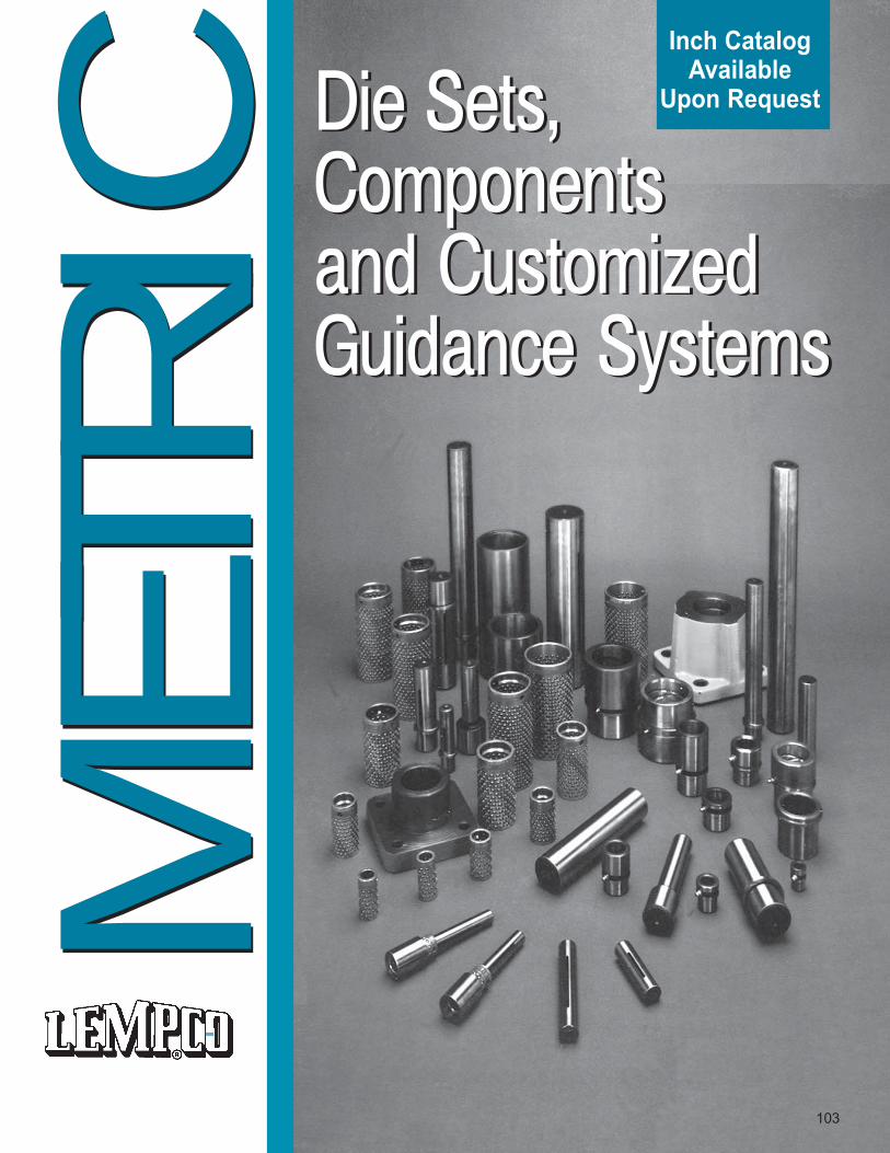
Die Sets,Componentsand CustomizedGuidance Systems
Die Sets,Componentsand CustomizedGuidance Systems
MET
RIC
103
Inch CatalogAvailable
Upon Request
MET
RIC
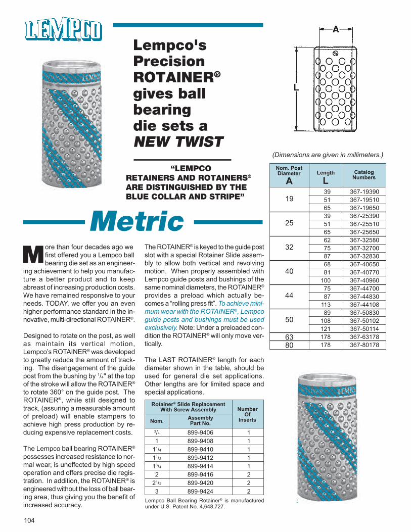
104
Lempco'sPrecisionROTAINER®
gives ballbearingdie sets aNEW TWIST
“LEMPCORETAINERS AND ROTAINERS®
ARE DISTINGUISHED BY THEBLUE COLLAR AND STRIPE”
ore than four decades ago wefirst offered you a Lempco ballbearing die set as an engineer-
ing achievement to help you manufac-ture a better product and to keepabreast of increasing production costs.We have remained responsive to yourneeds. TODAY, we offer you an evenhigher performance standard in the in-novative, multi-directional ROTAINER®.
Designed to rotate on the post, as wellas maintain its vertical motion,Lempco’s ROTAINER® was developedto greatly reduce the amount of track-ing. The disengagement of the guidepost from the bushing by 1/4" at the topof the stroke will allow the ROTAINER®
to rotate 360° on the guide post. TheROTAINER®, while still designed totrack, (assuring a measurable amountof preload) will enable stampers toachieve high press production by re-ducing expensive replacement costs.
The Lempco ball bearing ROTAINER®
possesses increased resistance to nor-mal wear, is uneffected by high speedoperation and offers precise die regis-tration. In addition, the ROTAINER® isengineered without the loss of ball bear-ing area, thus giving you the benefit ofincreased accuracy.
The ROTAINER® is keyed to the guide postslot with a special Rotainer Slide assem-bly to allow both vertical and revolvingmotion. When properly assembled withLempco guide posts and bushings of thesame nominal diameters, the ROTAINER®
provides a preload which actually be-comes a “rolling press fit”. To achieve mini-mum wear with the ROTAINER®, Lempcoguide posts and bushings must be usedexclusively. Note: Under a preloaded con-dition the ROTAINER® will only move ver-tically.
The LAST ROTAINER® length for eachdiameter shown in the table, should beused for general die set applications.Other lengths are for limited space andspecial applications.
M
Lempco Ball Bearing Rotainer® is manufacturedunder U.S. Patent No. 4,648,727.
Rotainer® Slide ReplacementWith Screw Assembly
Nom. AssemblyPart No.
NumberOf
Inserts
3/4 899-9406 11 899-9408 1
11/4 899-9410 111/2 899-9412 113/4 899-9414 12 899-9416 2
21/2 899-9420 23 899-9424 2
(Dimensions are given in millimeters.)
Nom. PostDiameter Length Catalog
NumbersA L
19
25
32
40
44
50
6380
39 367-1939051 367-1951065 367-1965039 367-2539051 367-2551065 367-2565062 367-3258075 367-3270087 367-3283068 367-4065081 367-40770
100 367-4096075 367-4470087 367-44830
113 367-4410889 367-50830
108 367-50102121 367-50114178 367-63178178 367-80178
Metric
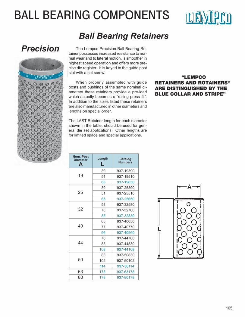
19
25
32
40
44
50
6380
BALL BEARING COMPONENTS
105
Ball Bearing RetainersPrecision
“LEMPCORETAINERS AND ROTAINERS®
ARE DISTINGUISHED BY THEBLUE COLLAR AND STRIPE”
The Lempco Precision Ball Bearing Re-tainer possesses increased resistance to nor-mal wear and to lateral motion, is smoother inhighest speed operation and offers more pre-cise die register. It is keyed to the guide postslot with a set screw.
When properly assembled with guideposts and bushings of the same nominal di-ameters these retainers provide a pre-loadwhich actually becomes a “rolling press fit”.In addition to the sizes listed these retainersare also manufactured in other diameters andlengths on special order.
The LAST Retainer length for each diametershown in the table, should be used for gen-eral die set applications. Other lengths arefor limited space and special applications.
Nom. PostDiameter Length Catalog
NumbersA L39 937-1939051 937-1951065 937-1965039 937-2539051 937-2551065 937-2565058 937-3258070 937-3270083 937-3283065 937-4065077 937-4077096 937-4096070 937-4470083 937-44830
108 937-4410883 937-50830
102 937-50102114 937-50114178 937-63178178 937-80178
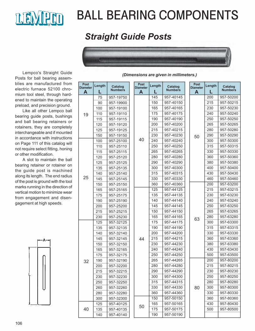
106
BALL BEARING COMPONENTS
Straight Guide Posts
Lempco's Straight GuidePosts for ball bearing assem-blies are manufactured fromelectric furnace 52100 chro-mium tool steel, through hard-ened to maintain the operatingpreload, and precision ground.
Like all other Lempco ballbearing guide posts, bushingsand ball bearing retainers orrotainers, they are completelyinterchangeable and if mountedin accordance with instructionson Page 111 of this catalog willnot require select fitting, honingor other modification.
A slot to maintain the ballbearing retainer or rotainer onthe guide post is machinedalong its length. The end radiusof the post is ground with the toolmarks running in the direction ofvertical motion to minimize wearfrom engagement and disen-gagement at high speeds.
PostDiameter Length Catalog
NumbersA LPost
Diameter Length CatalogNumbersA L
PostDiameter Length Catalog
NumbersA L
(Dimensions are given in millimeters.)
19
25
32
40
40
44
50
80
63
50
75 957-1975090 957-19900
100 957-19100110 957-19110115 957-19115120 957-19120125 957-19125150 957-19150100 957-25100110 957-25110115 957-25115120 957-25120125 957-25125135 957-25135140 957-25140145 957-25145150 957-25150165 957-25165175 957-25175190 957-25190200 957-25200215 957-25215230 957-25230125 957-32125135 957-32135140 957-32140145 957-32145150 957-32150165 957-32165175 957-32175190 957-32190200 957-32200215 957-32215230 957-32230250 957-32250260 957-32260280 957-32280300 957-32300125 957-40125135 957-40135140 957-40140
145 957-40145150 957-40150165 957-40165175 957-40175190 957-40190200 957-40200215 957-40215230 957-40230240 957-40240250 957-40250265 957-40265280 957-40280290 957-40290300 957-40300315 957-40315330 957-40330360 957-40360125 957-44125135 957-44135140 957-44140145 957-44145150 957-44150165 957-44165175 957-44175190 957-44190200 957-44200215 957-44215230 957-44230240 957-44240250 957-44250265 957-44265280 957-44280290 957-44290300 957-44300315 957-44315330 957-44330360 957-44360150 957-50150165 957-50165175 957-50175190 957-50190
200 957-50200215 957-50215230 957-50230240 957-50240250 957-50250265 957-50265280 957-50280290 957-50290300 957-50300315 957-50315330 957-50330360 957-50360380 957-50380400 957-50400430 957-50430460 957-50460200 957-63200215 957-63215230 957-63230240 957-63240250 957-63250265 957-63265280 957-63280300 957-63300315 957-63315330 957-63330360 957-63360380 957-63380430 957-63430500 957-63500200 957-80200215 957-80215230 957-80230250 957-80250280 957-80280300 957-80300330 957-80330360 957-80360430 957-80430500 957-80500
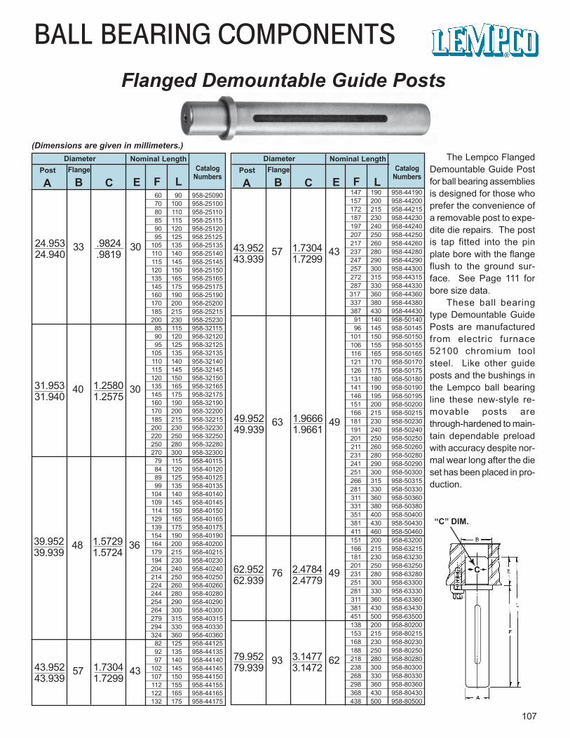
60 90 958-2509070 100 958-2510080 110 958-2511085 115 958-2511590 120 958-2512095 125 958.25125
105 135 958-25135110 140 958-25140115 145 958-25145120 150 958-25150135 165 958-25165145 175 958-25175160 190 958-25190170 200 958-25200185 215 958-25215200 230 958-2523085 115 958-3211590 120 958-3212095 125 958-32125
105 135 958-32135110 140 958-32140115 145 958-32145120 150 958-32150135 165 958-32165145 175 958-32175160 190 958-32190170 200 958-32200185 215 958-32215200 230 958-32230220 250 958-32250250 280 958-32280270 300 958-3230079 115 958-4011584 120 958-4012089 125 958-4012599 135 958-40135
104 140 958-40140109 145 958-40145114 150 958-40150129 165 958-40165139 175 958-40175154 190 958-40190164 200 958-40200179 215 958-40215194 230 958-40230204 240 958-40240214 250 958-40250 224 260 958-40260 244 280 958-40280 254 290 958-40290 264 300 958-40300 279 315 958-40315 294 330 958-40330 324 360 958-40360
82 125 958-44125 92 135 958-44135 97 140 958-44140
102 145 958-44145 107 150 958-44150 112 155 958-44155 122 165 958-44165 132 175 958-44175
BALL BEARING COMPONENTSFlanged Demountable Guide Posts
107
Diameter Nominal LengthCatalog
NumbersPost Flange
A B C E F L
24.953 33 .9824 3024.940 .9819
The Lempco FlangedDemountable Guide Postfor ball bearing assembliesis designed for those whoprefer the convenience ofa removable post to expe-dite die repairs. The postis tap fitted into the pinplate bore with the flangeflush to the ground sur-face. See Page 111 forbore size data.
These ball bearingtype Demountable GuidePosts are manufacturedfrom electric furnace52100 chromium toolsteel. Like other guideposts and the bushings inthe Lempco ball bearingline these new-style re-movable posts arethrough-hardened to main-tain dependable preloadwith accuracy despite nor-mal wear long after the dieset has been placed in pro-duction.
Diameter Nominal LengthCatalog
NumbersPost Flange
A B C E F L
“C” DIM.
31.953 40 1.2580 3031.940 1.2575
39.952 48 1.5729 3639.939 1.5724
43.952 57 1.7304 4343.939 1.7299
43.952 57 1.7304 4343.939 1.7299
49.952 63 1.9666 4949.939 1.9661
62.952 76 2.4784 4962.939 2.4779
79.952 93 3.1477 6279.939 3.1472
147 190 958-44190 157 200 958-44200 172 215 958-44215187 230 958-44230197 240 958-44240207 250 958-44250217 260 958-44260 237 280 958-44280 247 290 958-44290257 300 958-44300272 315 958-44315287 330 958-44330
317 360 958-44360 337 380 958-44380387 430 958-4443091 140 958-50140
. 96 145 958-50145 101 150 958-50150106 155 958-50155116 165 958-50165121 170 958-50170126 175 958-50175131 180 958-50180 141 190 958-50190 146 195 958-50195 151 200 958-50200 166 215 958-50215 181 230 958-50230191 240 958-50240201 250 958-50250211 260 958-50260
231 280 958-50280241 290 958-50290251 300 958-50300266 315 958-50315 281 330 958-50330311 360 958-50360331 380 958-50380351 400 958-50400381 430 958-50430411 460 958-50460151 200 958-63200166 215 958-63215181 230 958-63230201 250 958-63250231 280 958-63280251 300 958-63300281 330 958-63330311 360 958-63360381 430 958-63430451 500 958-63500138 200 958-80200153 215 958-80215 168 230 958-80230188 250 958-80250218 280 958-80280238 300 958-80300268 330 958-80330 298 360 958-80360368 430 958-80430 438 500 958-80500
(Dimensions are given in millimeters.)
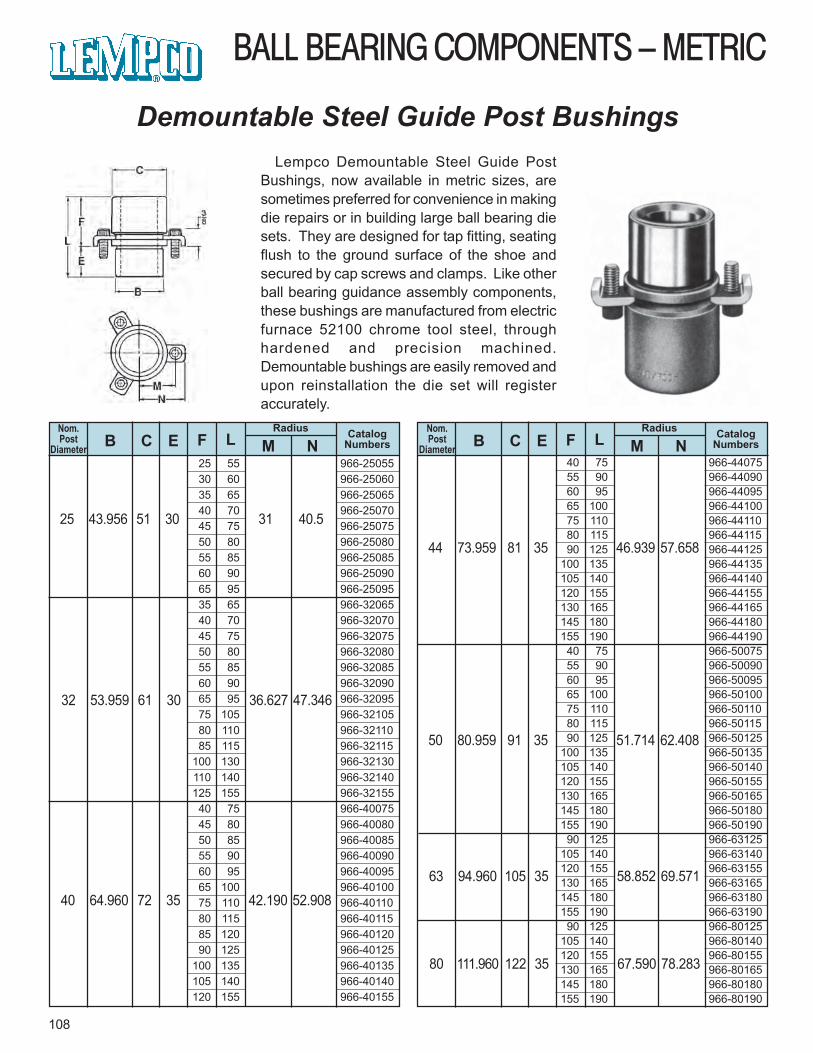
BALL BEARING COMPONENTS – METRIC
108
Demountable Steel Guide Post Bushings
Nom.Post
Diameter B C E FRadius
M NCatalog
NumbersL
25 43.956 51 30 31 40.5
Lempco Demountable Steel Guide PostBushings, now available in metric sizes, aresometimes preferred for convenience in makingdie repairs or in building large ball bearing diesets. They are designed for tap fitting, seatingflush to the ground surface of the shoe andsecured by cap screws and clamps. Like otherball bearing guidance assembly components,these bushings are manufactured from electricfurnace 52100 chrome tool steel, throughhardened and precision machined.Demountable bushings are easily removed andupon reinstallation the die set will registeraccurately.
Nom.Post
Diameter B C E FRadius
M NCatalog
NumbersL
32 53.959 61 30 36.627 47.346
40 64.960 72 35 42.190 52.908
44 73.959 81 35 46.939 57.658
50 80.959 91 35 51.714 62.408
63 94.960 105 35 58.852 69.571
80 111.960 122 35 67.590 78.283
25 55 966-2505530 60 966-2506035 65 966-2506540 70 966-2507045 75 966-2507550 80 966-2508055 85 966-2508560 90 966-2509065 95 966-2509535 65 966-3206540 70 966-3207045 75 966-3207550 80 966-3208055 85 966-3208560 90 966-3209065 95 966-3209575 105 966-3210580 110 966-3211085 115 966-32115
100 130 966-32130110 140 966-32140125 155 966-3215540 75 966-4007545 80 966-4008050 85 966-4008555 90 966-4009060 95 966-4009565 100 966-4010075 110 966-4011080 115 966-4011585 120 966-4012090 125 966-40125
100 135 966-40135105 140 966-40140120 155 966-40155
40 75 966-4407555 90 966-4409060 95 966-4409565 100 966-4410075 110 966-4411080 115 966-4411590 125 966-44125
100 135 966-44135105 140 966-44140120 155 966-44155130 165 966-44165145 180 966-44180155 190 966-4419040 75 966-5007555 90 966-5009060 95 966-5009565 100 966-5010075 110 966-5011080 115 966-5011590 125 966-50125
100 135 966-50135105 140 966-50140120 155 966-50155130 165 966-50165145 180 966-50180155 190 966-5019090 125 966-63125
105 140 966-63140120 155 966-63155130 165 966-63165145 180 966-63180155 190 966-6319090 125 966-80125
105 140 966-80140120 155 966-80155130 165 966-80165145 180 966-80180155 190 966-80190
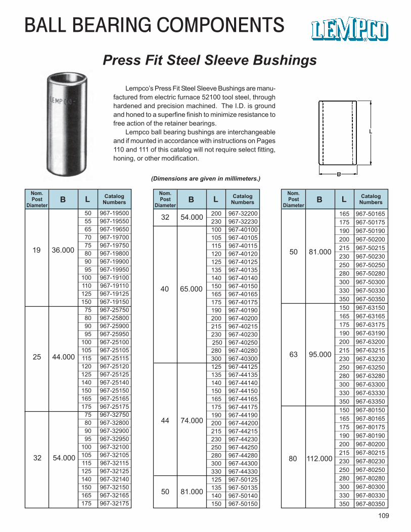
BALL BEARING COMPONENTS
Press Fit Steel Sleeve Bushings
109
Lempco’s Press Fit Steel Sleeve Bushings are manu-factured from electric furnace 52100 tool steel, throughhardened and precision machined. The I.D. is groundand honed to a superfine finish to minimize resistance tofree action of the retainer bearings.
Lempco ball bearing bushings are interchangeableand if mounted in accordance with instructions on Pages110 and 111 of this catalog will not require select fitting,honing, or other modification.
(Dimensions are given in millimeters.)
Nom.Post
DiameterCatalog
NumbersB LNom.Post
DiameterCatalog
NumbersB LNom.Post
DiameterCatalog
NumbersB L
19 36.000
25 44.000
32 54.000
32 54.000
40 65.000
44 74.000
50 81.000
50 81.000
63 95.000
80 112.000
50 967-1950055 967-1955065 967-1965070 967-1970075 967-1975080 967-1980090 967-1990095 967-19950
100 967-19100 110 967-19110 125 967-19125150 967-19150 75 967-2575080 967-2580090 967-2590095 967-25950
100 967-25100 105 967-25105 115 967-25115 120 967-25120125 967-25125
140 967-25140 150 967-25150 165 967-25165 175 967-25175
75 967-3275080 967-3280090 967-3290095 967-32950
100 967-32100 105 967-32105 115 967-32115 125 967-32125 140 967-32140 150 967-32150 165 967-32165 175 967-32175
200 967-32200230 967-32230100 967-40100105 967-40105115 967-40115120 967-40120125 967-40125135 967-40135140 967-40140150 967-40150165 967-40165175 967-40175190 967-40190200 967-40200215 967-40215230 967-40230 250 967-40250280 967-40280300 967-40300125 967-44125135 967-44135140 967-44140150 967-44150165 967-44165175 967-44175190 967-44190200 967-44200215 967-44215230 967-44230250 967-44250280 967-44280300 967-44300330 967-44330125 967-50125135 967-50135140 967-50140150 967-50150
165 967-50165175 967-50175190 967-50190200 967-50200215 967-50215230 967-50230250 967-50250280 967-50280300 967-50300330 967-50330350 967-50350150 967-63150165 967-63165175 967-63175190 967-63190200 967-63200215 967-63215230 967-63230250 967-63250280 967-63280300 967-63300330 967-63330350 967-63350150 967-80150165 967-80165175 967-80175190 967-80190200 967-80200215 967-80215230 967-80230250 967-80250280 967-80280300 967-80300330 967-80330350 967-80350
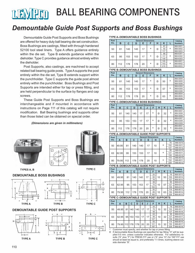
67 968-500192 968-5002
117 968-500386 968-6301
117 968-6302149 968-6303105 968-8001143 968-8002219 968-8003
50 81 140 140 17 * Ð 50 *
63 95 153 153 17 * Ð 57 *
80 112 178 178 20 * Ð 63 *
968-5004968-5005968-5006968-6304968-6305968-6306968-8004968-8005968-8006
76 968-5010102 968-5011127 968-5012
95 968-6310127 968-6311159 968-6312114 968-8010152 968-8011229 968-8012
50 81 140 140 17 * Ð *
63 95 153 153 17 * Ð *
80 112 178 178 20 * Ð *
110
BALL BEARING COMPONENTS
Demountable Guide Post Supports and Boss BushingsDemountable Guide Post Supports and Boss Bushings
are offered for heavy duty ball bearing die set construction.Boss Bushings are castings, fitted with through hardened52100 tool steel liners. Type A offers guidance entirelywithin the die set. Type B extends guidance within thedieholder. Type C provides guidance almost entirely withinthe dieholder.
Post Supports, also castings, are machined to acceptrelated ball bearing guide posts. Type A supports the postentirely within the die set, Type B extends support withinthe punchholder. Type C supports the guide post almostentirely within the punchholder. Boss Bushings and PostSupports are intended either for tap or press fitting, andare held perpendicular to the surface by flanges and capscrews.
These Guide Post Supports and Boss Bushings areinterchangeable and if mounted in accordance withinstructions on Page 111 of this catalog will not requiremodification. Ball Bearing bushings and supports otherthan those listed can be obtained on special order.
TYPES A, B TYPE C
TYPE C
DEMOUNTABLE BOSS BUSHINGS
TYPE A TYPE B
TYPE CTYPE A TYPE B
DEMOUNTABLE GUIDE POST SUPPORTS
CatalogNumbers
PostDia.
General DimensionsB C D E F H K L
TYPE A–DEMOUNTABLE BOSS BUSHINGS
TYPE B–DEMOUNTABLE BOSS BUSHINGS
TYPE C–DEMOUNTABLE BOSS BUSHINGS
CatalogNumbers
PostDia.
General DimensionsB C D E H K L
TYPE A–DEMOUNTABLE GUIDE POST SUPPORTS
A
TYPE B–DEMOUNTABLE GUIDE POST SUPPORTS
TYPE C–DEMOUNTABLE GUIDE POST SUPPORTS
* Customer must specify, and whether for tap or press fitting.Ð If demountable Boss Bushings are specified for tap fitting “H” will be sup-
plied 9.5 mm. unless customer indicates otherwise. For satisfactory re-sults (“K” plus “F”) for PRESS FIT use or (“K” plus “H”) for TAP FIT useshould at least be equal to, and preferably 11/2 times, bushing sleeve out-side diameter “B”.
(Dimensions are given in millimeters)
CatalogNumbers
PostDia.
General DimensionsB C D E F H K L
50 81 140 140 17 17 * Ð 32 *
63 95 153 153 17 17 * Ð 32 *
80 112 178 178 20 20 * Ð 32 *
968-5007968-5008968-5009968-6307968-6308968-6309968-8007968-8008968-8009
CatalogNumbers
PostDia.
General DimensionsB C D E J H K LF
50 49.95 81 140 140 17 10 *
63 62.95 95 153 153 17 10 *
80 79.95 112 178 178 20 10 *
50 49.95 81 140 140 17 10 50
63 62.95 95 153 153 17 10 57
80 79.95 112 178 178 20 10 63
25 76 968-501350 102 968-501476 127 968-501538 95 968-631370 127 968-6314
102 159 968-631550 114 968-801389 152 968-8014
165 229 968-8015
CatalogNumbers
PostDia.
General DimensionsA B C D E H K LF
CatalogNumbers
PostDia.
General DimensionsA B C D E H K LFJ
50 49.95 81 140 140 17 17 10 32
63 62.95 95 153 153 17 17 10 32
80 79.95 112 178 178 20 20 10 32
44 76 968-501670 102 968-501795 127 968-501863 95 968-631695 127 968-6317
127 159 968-631883 114 968-8016
121 152 968-8017197 229 968-8018
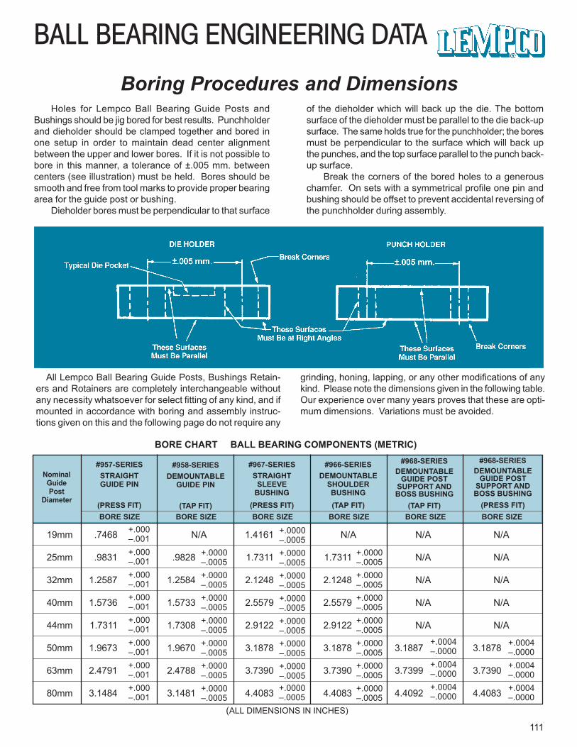
BALL BEARING ENGINEERING DATA
111
Boring Procedures and DimensionsHoles for Lempco Ball Bearing Guide Posts and
Bushings should be jig bored for best results. Punchholderand dieholder should be clamped together and bored inone setup in order to maintain dead center alignmentbetween the upper and lower bores. If it is not possible tobore in this manner, a tolerance of ±.005 mm. betweencenters (see illustration) must be held. Bores should besmooth and free from tool marks to provide proper bearingarea for the guide post or bushing.
Dieholder bores must be perpendicular to that surface
of the dieholder which will back up the die. The bottomsurface of the dieholder must be parallel to the die back-upsurface. The same holds true for the punchholder; the boresmust be perpendicular to the surface which will back upthe punches, and the top surface parallel to the punch back-up surface.
Break the corners of the bored holes to a generouschamfer. On sets with a symmetrical profile one pin andbushing should be offset to prevent accidental reversing ofthe punchholder during assembly.
All Lempco Ball Bearing Guide Posts, Bushings Retain-ers and Rotainers are completely interchangeable withoutany necessity whatsoever for select fitting of any kind, and ifmounted in accordance with boring and assembly instruc-tions given on this and the following page do not require any
grinding, honing, lapping, or any other modifications of anykind. Please note the dimensions given in the following table.Our experience over many years proves that these are opti-mum dimensions. Variations must be avoided.
BORE CHART BALL BEARING COMPONENTS (METRIC)
NominalGuidePost
Diameter
#957-SERIESSTRAIGHTGUIDE PIN
(PRESS FIT)
#958-SERIESDEMOUNTABLE
GUIDE PIN
(TAP FIT)
#967-SERIESSTRAIGHT
SLEEVEBUSHING
(PRESS FIT)
#966-SERIESDEMOUNTABLE
SHOULDERBUSHING(TAP FIT)
#968-SERIESDEMOUNTABLE
GUIDE POSTSUPPORT ANDBOSS BUSHING
(TAP FIT)
#968-SERIESDEMOUNTABLE
GUIDE POSTSUPPORT ANDBOSS BUSHING
(PRESS FIT)BORE SIZE
19mm .7468 N/A 1.4161 N/A N/A N/A
25mm .9831 .9828 1.7311 1.7311 N/A N/A
32mm 1.2587 1.2584 2.1248 2.1248 N/A N/A
40mm 1.5736 1.5733 2.5579 2.5579 N/A N/A
44mm 1.7311 1.7308 2.9122 2.9122 N/A N/A
50mm 1.9673 1.9670 3.1878 3.1878 3.1887 3.1878
63mm 2.4791 2.4788 3.7390 3.7390 3.7399 3.7390
80mm 3.1484 3.1481 4.4083 4.4083 4.4092 4.4083
BORE SIZE BORE SIZE BORE SIZE BORE SIZE BORE SIZE+.000–.001
+.0000–.0005
+.0000–.0005
+.000–.001+.000–.001+.000–.001+.000–.001+.000–.001+.000–.001+.000–.001
+.0000–.0005+.0000–.0005+.0000–.0005+.0000–.0005+.0000–.0005+.0000–.0005
+.0000–.0005+.0000–.0005+.0000–.0005+.0000–.0005+.0000–.0005+.0000–.0005+.0000–.0005
+.0004–.0000
+.0004–.0000
+.0004–.0000+.0004–.0000
+.0004–.0000+.0004–.0000
+.0000–.0005+.0000–.0005+.0000–.0005+.0000–.0005+.0000–.0005+.0000–.0005+.0000–.0005
(ALL DIMENSIONS IN INCHES)
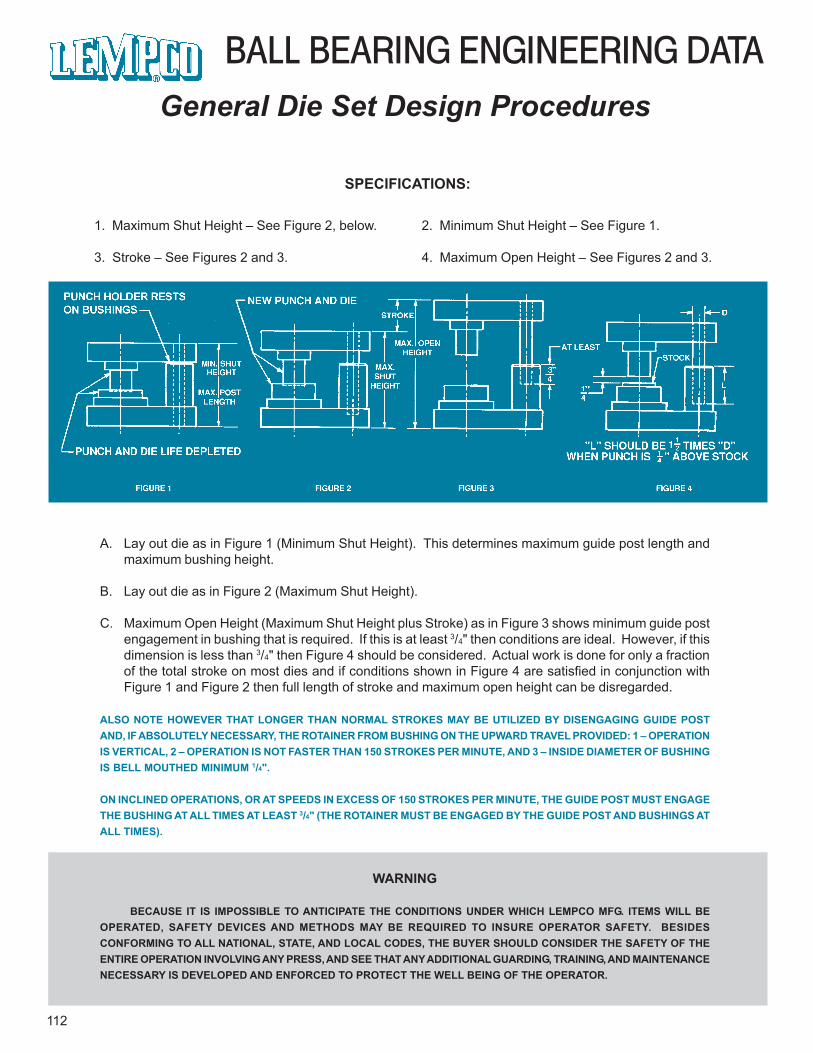
BALL BEARING ENGINEERING DATA
112
General Die Set Design Procedures
SPECIFICATIONS:
1. Maximum Shut Height – See Figure 2, below.
3. Stroke – See Figures 2 and 3.
2. Minimum Shut Height – See Figure 1.
4. Maximum Open Height – See Figures 2 and 3.
A. Lay out die as in Figure 1 (Minimum Shut Height). This determines maximum guide post length andmaximum bushing height.
B. Lay out die as in Figure 2 (Maximum Shut Height).
C. Maximum Open Height (Maximum Shut Height plus Stroke) as in Figure 3 shows minimum guide postengagement in bushing that is required. If this is at least 3/4" then conditions are ideal. However, if thisdimension is less than 3/4" then Figure 4 should be considered. Actual work is done for only a fractionof the total stroke on most dies and if conditions shown in Figure 4 are satisfied in conjunction withFigure 1 and Figure 2 then full length of stroke and maximum open height can be disregarded.
ALSO NOTE HOWEVER THAT LONGER THAN NORMAL STROKES MAY BE UTILIZED BY DISENGAGING GUIDE POSTAND, IF ABSOLUTELY NECESSARY, THE ROTAINER FROM BUSHING ON THE UPWARD TRAVEL PROVIDED: 1 – OPERATIONIS VERTICAL, 2 – OPERATION IS NOT FASTER THAN 150 STROKES PER MINUTE, AND 3 – INSIDE DIAMETER OF BUSHINGIS BELL MOUTHED MINIMUM 1/4".
ON INCLINED OPERATIONS, OR AT SPEEDS IN EXCESS OF 150 STROKES PER MINUTE, THE GUIDE POST MUST ENGAGETHE BUSHING AT ALL TIMES AT LEAST 3/4" (THE ROTAINER MUST BE ENGAGED BY THE GUIDE POST AND BUSHINGS ATALL TIMES).
WARNING
BECAUSE IT IS IMPOSSIBLE TO ANTICIPATE THE CONDITIONS UNDER WHICH LEMPCO MFG. ITEMS WILL BEOPERATED, SAFETY DEVICES AND METHODS MAY BE REQUIRED TO INSURE OPERATOR SAFETY. BESIDESCONFORMING TO ALL NATIONAL, STATE, AND LOCAL CODES, THE BUYER SHOULD CONSIDER THE SAFETY OF THEENTIRE OPERATION INVOLVING ANY PRESS, AND SEE THAT ANY ADDITIONAL GUARDING, TRAINING, AND MAINTENANCENECESSARY IS DEVELOPED AND ENFORCED TO PROTECT THE WELL BEING OF THE OPERATOR.
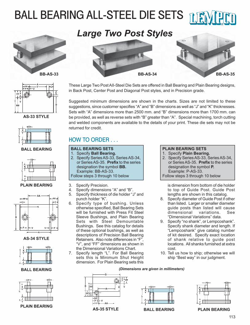
113
BALL BEARING ALL-STEEL DIE SETSLarge Two Post Styles
BB-AS-33 BB-AS-34 BB-AS-35
AS-33 STYLE
BALL BEARING
PLAIN BEARING
AS-34 STYLE
BALL BEARING
PLAIN BEARINGAS-35 STYLE BALL BEARING PLAIN BEARING
These Large Two Post AII-Steel Die Sets are offered in Ball Bearing and Plain Bearing designs,in Back Post, Center Post and Diagonal Post styles, and in Precision grade.
Suggested minimum dimensions are shown in the charts. Sizes are not limited to thesesuggestions, since customer specifies “A” and “B” dimensions as well as “J” and “K” thicknesses.Sets with “A” dimensions more than 2500 mm. and “B” dimensions more than 1700 mm. canbe provided, as well as reverse sets with “B” greater than “A”. Special machining, torch cuttingand welded components are available to the details of your print. These die sets may not bereturned for credit.
HOW TO ORDER . . .BALL BEARING SETS1. Specify Ball Bearing.2. Specify Series AS-33, Series AS-34,
or Series AS-35. Prefix to the seriesdesignation the symbol BB.Example: BB-AS-33.
Follow steps 3 through 10 below
PLAIN BEARING SETS1. Specify Plain Bearing.2. Specify Series AS-33, Series AS-34,
or Series AS-35. Prefix to the seriesdesignation the symbol P.Example: P-AS-33.
Follow steps 3 through 10 below
3. Specify Precision.4. Specify dimensions “A” and “B”.5. Specify thickness of die holder “J” and
punch holder “K”.6. Specify type of bushing. Unless
otherwise specified, Ball Bearing Setswill be furnished with Press Fit SteelSleeve Bushings, and Plain BearingSets with Steel DemountableBushings. See this catalog for detailsof these optional bushings, as well asdescriptions of Precision Ball BearingRetainers. Also note differences in “F”,“V”, and “FF” dimensions as shown inthe Dimensional Variations Chart.
7. Specify length “L”. For Ball Bearingsets this is Minimum Shut Heightdimension. For Plain Bearing sets this
is dimension from bottom of die holderto top of Guide Post. Guide Postlengths are shown in this catalog.
8. Specify diameter of Guide Post if otherthan listed. Larger or smaller diameterguide posts than listed will causedimensional variations. See“Dimensional Variations” data.
9. Specify “no shank”, or Lempcoshank”.Specify shank diameter and length. If“Lempcoshank” give catalog numberof kit desired. Specify exact locationof shank relative to guide postlocations. All shanks furnished at extracost.
10. Tell us how to ship; otherwise we willship “Best way” in our judgment.
(Dimensions are given in millimeters)
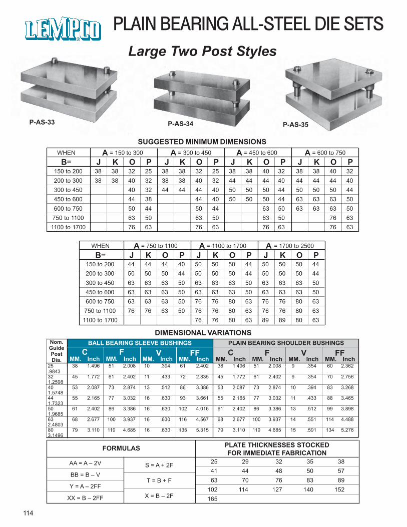
25 38 1.496 51 2.008 10 .394 61 2.402 38 1.496 51 2.008 9 .354 60 2.362.984332 45 1.772 61 2.402 11 .433 72 2.835 45 1.772 61 2.402 9 .354 70 2.7561.259840 53 2.087 73 2.874 13 .512 86 3.386 53 2.087 73 2.874 10 .394 83 3.2681.574844 55 2.165 77 3.032 16 .630 93 3.661 55 2.165 77 3.032 11 .433 88 3.4651.732350 61 2.402 86 3.386 16 .630 102 4.016 61 2.402 86 3.386 13 .512 99 3.8981.968563 68 2.677 100 3.937 16 .630 116 4.567 68 2.677 100 3.937 14 .551 114 4.4882.480380 79 3.110 119 4.685 16 .630 135 5.315 79 3.110 119 4.685 15 .591 134 5.2763.1496
150 to 200 44 44 44 40 50 50 50 44 50 50 50 44200 to 300 50 50 50 44 50 50 50 44 50 50 50 44300 to 450 63 63 63 50 63 63 63 50 63 63 63 50450 to 600 63 63 63 50 63 63 63 50 63 63 63 50600 to 750 63 63 63 50 76 76 80 63 76 76 80 63750 to 1100 76 76 63 50 76 76 80 63 76 76 80 63
1100 to 1700 76 76 80 63 89 89 80 63
WHEN A = 750 to 1100 A = 1100 to 1700 A = 1700 to 2500
B= J K O P J K O P J K O P
150 to 200 38 38 32 25 38 38 32 25 38 38 40 32 38 38 40 32200 to 300 38 38 40 32 38 38 40 32 44 44 44 40 44 44 44 40300 to 450 40 32 44 44 44 40 50 50 50 44 50 50 50 44450 to 600 44 38 44 40 50 50 50 44 63 63 63 50600 to 750 50 44 50 44 63 50 63 63 63 50750 to 1100 63 50 63 50 63 50 76 631100 to 1700 76 63 76 63 76 63 76 63
WHEN A = 150 to 300 A = 300 to 450 A = 450 to 600 A = 600 to 750
B= J K O P J K O P J K O P J K O P
PLAIN BEARING ALL-STEEL DIE SETSLarge Two Post Styles
P-AS-33 P-AS-34 P-AS-35
DIMENSIONAL VARIATIONS
SUGGESTED MINIMUM DIMENSIONS
114
FORMULAS PLATE THICKNESSES STOCKEDFOR IMMEDIATE FABRICATION
AA = A – 2V
BB = B – V
Y = A – 2FF
XX = B – 2FF
S = A + 2F
T = B + F
X = B – 2F
25 29 32 35 38 41 44 48 50 57 63 70 76 83 89102 114 127 140 152165
Nom.GuidePostDia.
BALL BEARING SLEEVE BUSHINGSC F V FF
PLAIN BEARING SHOULDER BUSHINGSC F V FF
MM. Inch MM. Inch MM. Inch MM. Inch MM. Inch MM. Inch MM. Inch MM. Inch
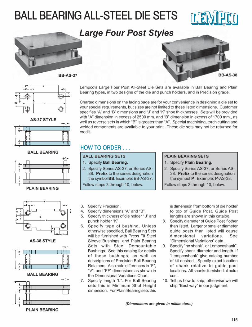
115
BALL BEARING ALL-STEEL DIE SETSLarge Four Post Styles
BB-AS-37 BB-AS-38
AS-37 STYLE
BALL BEARING
PLAIN BEARING
AS-38 STYLE
BALL BEARING
PLAIN BEARING
Lempco's Large Four Post All-Steel Die Sets are available in Ball Bearing and PlainBearing types, in two designs of the die and punch holders, and in Precision grade.
Charted dimensions on the facing page are for your convenience in designing a die set toyour special requirements, but sizes are not limited to these listed dimensions. Customerspecifies “A” and “B” dimensions and “J” and “K” shoe thicknesses. Sets will be providedwith “A” dimension in excess of 2500 mm. and “B” dimension in excess of 1700 mm., aswell as reverse sets in which “B” is greater than “A”. Special machining, torch cutting andwelded components are available to your print. These die sets may not be returned forcredit.
HOW TO ORDER . . .BALL BEARING SETS1. Specify Ball Bearing.2. Specify Series AS-37, or Series AS-
38. Prefix to the series designationthe symbol BB. Example: BB-AS-37.
Follow steps 3 through 10, below.
PLAIN BEARING SETS1. Specify Plain Bearing.2. Specify Series AS-37, or Series AS-
38. Prefix to the series designationthe symbol P. Example: P-AS-38.
Follow steps 3 through 10, below.
3. Specify Precision.4. Specify dimensions “A” and “B”.5. Specify thickness of die holder “ J” and
punch holder “K”.6. Specify type of bushing. Unless
otherwise specified, Ball Bearing Setswill be furnished with Press Fit SteelSleeve Bushings, and Plain BearingSets with Steel DemountableBushings. See this catalog for detailsof these bushings, as well asdescriptions of Precision Ball BearingRetainers. Also note differences in “F”,“V”, and “FF” dimensions as shown inthe Dimensional Variations Chart.
7. Specify length “L”. For Ball Bearingsets this is Minimum Shut Heightdimension. For Plain Bearing sets this
is dimension from bottom of die holderto top of Guide Post. Guide Postlengths are shown in this catalog.
8. Specify diameter of Guide Post if otherthan listed. Larger or smaller diameterguide posts than listed will causedimensional variations. See“Dimensional Variations” data.
9. Specify “no shank”, or Lempcoshank”.Specify shank diameter and length. If“Lempcoshank” give catalog numberof kit desired. Specify exact locationof shank relative to guide postlocations. All shanks furnished at extracost.
10. Tell us how to ship; otherwise we willship “Best way” in our judgment.
(Dimensions are given in millimeters.)
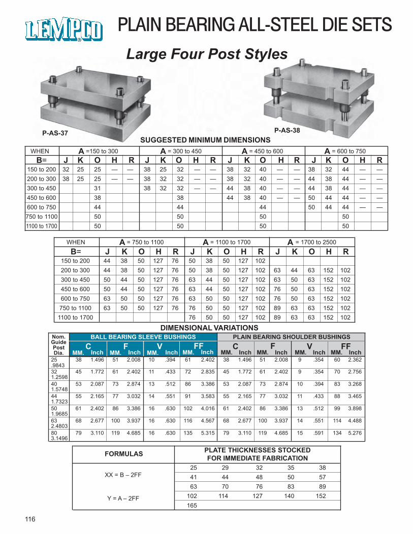
25 38 1.496 51 2.008 10 .394 61 2.402 38 1.496 51 2.008 9 .354 60 2.362.984332 45 1.772 61 2.402 11 .433 72 2.835 45 1.772 61 2.402 9 .354 70 2.7561.259840 53 2.087 73 2.874 13 .512 86 3.386 53 2.087 73 2.874 10 .394 83 3.2681.574844 55 2.165 77 3.032 14 .551 91 3.583 55 2.165 77 3.032 11 .433 88 3.4651.732350 61 2.402 86 3.386 16 .630 102 4.016 61 2.402 86 3.386 13 .512 99 3.8981.968563 68 2.677 100 3.937 16 .630 116 4.567 68 2.677 100 3.937 14 .551 114 4.4882.480380 79 3.110 119 4.685 16 .630 135 5.315 79 3.110 119 4.685 15 .591 134 5.2763.1496
150 to 200 32 25 25 — — 38 25 32 — — 38 32 40 — — 38 32 44 — —200 to 300 38 25 25 — — 38 32 32 — — 38 32 40 — — 44 38 44 — —300 to 450 31 38 32 32 — — 44 38 40 — — 44 38 44 — —450 to 600 38 38 44 38 40 — — 50 44 44 — —600 to 750 44 44 44 50 44 44 — —750 to 1100 50 50 50 501100 to 1700 50 50 50 50
150 to 200 44 38 50 127 76 50 38 50 127 102200 to 300 44 38 50 127 76 50 38 50 127 102 63 44 63 152 102300 to 450 50 44 50 127 76 63 44 50 127 102 63 50 63 152 102450 to 600 50 44 50 127 76 63 44 50 127 102 76 50 63 152 102600 to 750 63 50 50 127 76 63 50 50 127 102 76 50 63 152 102750 to 1100 63 50 50 127 76 76 50 50 127 102 89 63 63 152 102
1100 to 1700 76 50 50 127 102 89 63 63 152 102
WHEN A = 750 to 1100 A = 1100 to 1700 A = 1700 to 2500
B= J K O H R J K O H R J K O H R
B= J K O H R J K O H R J K O H R J K O H RWHEN A =150 to 300 A = 300 to 450 A = 450 to 600 A = 600 to 750
PLAIN BEARING ALL-STEEL DIE SETSLarge Four Post Styles
P-AS-37 P-AS-38
DIMENSIONAL VARIATIONS
SUGGESTED MINIMUM DIMENSIONS
116
FORMULAS PLATE THICKNESSES STOCKEDFOR IMMEDIATE FABRICATION
XX = B – 2FF
Y = A – 2FF
25 29 32 35 38 41 44 48 50 57 63 70 76 83 89102 114 127 140 152165
Nom.GuidePostDia.
BALL BEARING SLEEVE BUSHINGSC F V FF
PLAIN BEARING SHOULDER BUSHINGSC F V FF
MM. Inch MM. Inch MM. Inch MM. Inch MM. Inch MM. Inch MM. Inch MM. Inch
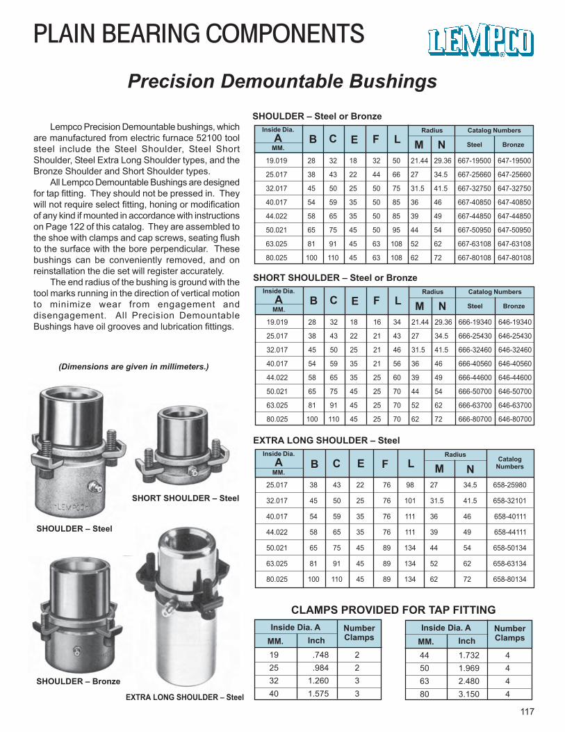
19 .748 225 .984 232 1.260 340 1.575 3
Inside Dia.A
25.017 38 43 22 76 98 27 34.5 658-25980
32.017 45 50 25 76 101 31.5 41.5 658-32101
40.017 54 59 35 76 111 36 46 658-40111
44.022 58 65 35 76 111 39 49 658-44111
50.021 65 75 45 89 134 44 54 658-50134
63.025 81 91 45 89 134 52 62 658-63134
80.025 100 110 45 89 134 62 72 658-80134
PLAIN BEARING COMPONENTS
117
Precision Demountable Bushings
Lempco Precision Demountable bushings, whichare manufactured from electric furnace 52100 toolsteel include the Steel Shoulder, Steel ShortShoulder, Steel Extra Long Shoulder types, and theBronze Shoulder and Short Shoulder types.
All Lempco Demountable Bushings are designedfor tap fitting. They should not be pressed in. Theywill not require select fitting, honing or modificationof any kind if mounted in accordance with instructionson Page 122 of this catalog. They are assembled tothe shoe with clamps and cap screws, seating flushto the surface with the bore perpendicular. Thesebushings can be conveniently removed, and onreinstallation the die set will register accurately.
The end radius of the bushing is ground with thetool marks running in the direction of vertical motionto minimize wear from engagement anddisengagement. All Precision DemountableBushings have oil grooves and lubrication fittings.
SHOULDER – Steel
SHOULDER – Bronze
EXTRA LONG SHOULDER – Steel
19.019 28 32 18 32 50 21.44 29.36 667-19500 647-19500
25.017 38 43 22 44 66 27 34.5 667-25660 647-25660
32.017 45 50 25 50 75 31.5 41.5 667-32750 647-32750
40.017 54 59 35 50 85 36 46 667-40850 647-40850
44.022 58 65 35 50 85 39 49 667-44850 647-44850
50.021 65 75 45 50 95 44 54 667-50950 647-50950
63.025 81 91 45 63 108 52 62 667-63108 647-63108
80.025 100 110 45 63 108 62 72 667-80108 647-80108
Inside Dia.A
MM.
Catalog NumbersB C E F L
SHOULDER – Steel or Bronze
Steel
SHORT SHOULDER – Steel
(Dimensions are given in millimeters.)
Bronze
Radius
M N
Inside Dia. AMM. Inch
NumberClamps
CLAMPS PROVIDED FOR TAP FITTING
19.019 28 32 18 16 34 21.44 29.36 666-19340 646-19340
25.017 38 43 22 21 43 27 34.5 666-25430 646-25430
32.017 45 50 25 21 46 31.5 41.5 666-32460 646-32460
40.017 54 59 35 21 56 36 46 666-40560 646-40560
44.022 58 65 35 25 60 39 49 666-44600 646-44600
50.021 65 75 45 25 70 44 54 666-50700 646-50700
63.025 81 91 45 25 70 52 62 666-63700 646-63700
80.025 100 110 45 25 70 62 72 666-80700 646-80700
Inside Dia.A
MM.
Catalog NumbersB C E F L
SHORT SHOULDER – Steel or Bronze
Steel Bronze
Radius
M N
MM.
CatalogNumbersB C E F L
EXTRA LONG SHOULDER – SteelRadius
M N
44 1.732 450 1.969 463 2.480 480 3.150 4
Inside Dia. AMM. Inch
NumberClamps
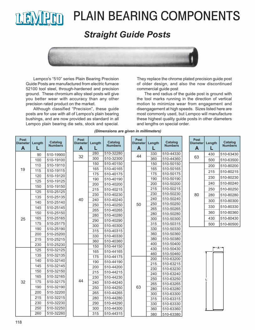
330 510-44330360 510-44360150 510-50150165 510-50165175 510-50175190 510-50190200 510-50200215 510-50215230 510-50230240 510-50240250 510-50250265 510-50265280 510-50280300 510-50300315 510-50315330 510-50330360 510-50360380 510-50380400 510-50400430 510-50430460 510-50460200 510-63200215 510-63215230 510-63230240 510-63240250 510-63250265 510-63265280 510-63280300 510-63300315 510-63315330 510-63330360 510-63360380 510-63380
90 510-19900100 510-19100110 510-19110115 510-19115120 510-19120125 510-19125150 510-19150125 510-25125135 510-25135140 510-25140145 510-25145150 510-25150165 510-25165175 510-25175190 510-25190200 510-25200215 510-25215230 510-25230125 510-32125135 510-32135140 510-32140145 510-32145150 510-32150165 510-32165175 510-32175190 510-32190200 510-32200215 510-32215230 510-32230250 510-32250260 510-32260
118
PLAIN BEARING COMPONENTSStraight Guide Posts
Lempco's “510” series Plain Bearing PrecisionGuide Posts are manufactured from electric furnace52100 tool steel, through-hardened and precisionground. These chromium alloy steel posts will giveyou better wear with accuracy than any otherprecision rated product on the market.
Although classified “Precision”, these guideposts are for use with all of Lempco's plain bearingbushings, and are now provided as standard in allLempco plain bearing die sets, stock and special.
They replace the chrome plated precision guide postof older design, and also the now discontinuedcommercial guide post
The end radius of the guide post is ground withthe tool marks running in the direction of verticalmotion to minimize wear from engagement anddisengagement at high speeds. Sizes listed here aremost commonly used, but Lempco will manufacturethese highest quality guide posts in other diametersand lengths on special order.
PostDiameter Length Catalog
NumbersA L
PostDiameter Length Catalog
NumbersA L
PostDiameter Length Catalog
NumbersA L
PostDiameter Length Catalog
NumbersA L
19
63
80
280 510-32280300 510-32300150 510-40150165 510-40165175 510-40175190 510-40190200 510-40200215 510-40215230 510-40230240 510-40240250 510-40250265 510-40265280 510-40280290 510-40290300 510-40300315 510-40315330 510-40330360 510-40360150 510-44150165 510-44165175 510-44175190 510-44190200 510-44200215 510-44215230 510-44230240 510-44240250 510-44250265 510-44265280 510-44280290 510-44290300 510-44300315 510-44315
(Dimensions are given in millimeters)
25
32
32
40
44
44
50
63
430 510-63430500 510-63500200 510-80200215 510-80215230 510-80230240 510-80240250 510-80250280 510-80280300 510-80300330 510-80330360 510-80360430 510-80430500 510-80500
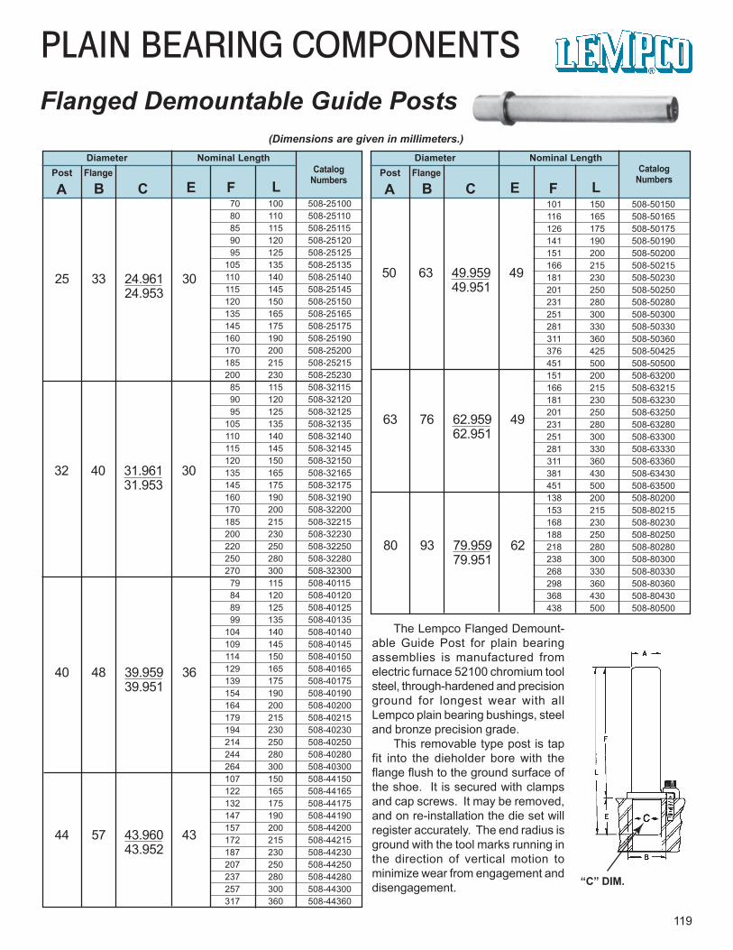
101 150 508-50150116 165 508-50165126 175 508-50175141 190 508-50190151 200 508-50200166 215 508-50215181 230 508-50230201 250 508-50250231 280 508-50280251 300 508-50300281 330 508-50330311 360 508-50360376 425 508-50425451 500 508-50500151 200 508-63200166 215 508-63215181 230 508-63230201 250 508-63250231 280 508-63280251 300 508-63300281 330 508-63330311 360 508-63360381 430 508-63430451 500 508-63500138 200 508-80200153 215 508-80215168 230 508-80230188 250 508-80250218 280 508-80280238 300 508-80300268 330 508-80330298 360 508-80360368 430 508-80430438 500 508-80500
70 100 508-25100 80 110 508-25110 85 115 508-25115 90 120 508-25120 95 125 508-25125105 135 508-25135110 140 508-25140115 145 508-25145120 150 508-25150135 165 508-25165145 175 508-25175160 190 508-25190170 200 508-25200185 215 508-25215200 230 508-25230 85 115 508-32115 90 120 508-32120 95 125 508-32125105 135 508-32135110 140 508-32140115 145 508-32145120 150 508-32150135 165 508-32165145 175 508-32175160 190 508-32190170 200 508-32200185 215 508-32215200 230 508-32230220 250 508-32250250 280 508-32280270 300 508-32300 79 115 508-40115 84 120 508-40120 89 125 508-40125 99 135 508-40135104 140 508-40140109 145 508-40145114 150 508-40150129 165 508-40165139 175 508-40175154 190 508-40190164 200 508-40200179 215 508-40215194 230 508-40230214 250 508-40250244 280 508-40280264 300 508-40300107 150 508-44150122 165 508-44165132 175 508-44175147 190 508-44190157 200 508-44200172 215 508-44215187 230 508-44230207 250 508-44250237 280 508-44280257 300 508-44300317 360 508-44360
PLAIN BEARING COMPONENTS
119
Flanged Demountable Guide Posts
Diameter Nominal LengthCatalog
NumbersPost Flange
A B C E F L
Diameter Nominal LengthCatalog
NumbersPost Flange
A B C E F L
The Lempco Flanged Demount-able Guide Post for plain bearingassemblies is manufactured fromelectric furnace 52100 chromium toolsteel, through-hardened and precisionground for longest wear with allLempco plain bearing bushings, steeland bronze precision grade.
This removable type post is tapfit into the dieholder bore with theflange flush to the ground surface ofthe shoe. It is secured with clampsand cap screws. It may be removed,and on re-installation the die set willregister accurately. The end radius isground with the tool marks running inthe direction of vertical motion tominimize wear from engagement anddisengagement.
25 33 24.961 3024.953
“C” DIM.
(Dimensions are given in millimeters.)
32 40 31.961 3031.953
40 48 39.959 3639.951
44 57 43.960 4343.952
63 76 62.959 4962.951
50 63 49.959 4949.951
80 93 79.959 6279.951
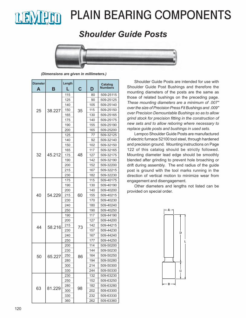
50 65.227 86
115 80 509-25115125 90 509-25125140 105 509-25140150 115 509-25150165 130 509-25165175 140 509-25175190 155 509-25190200 165 509-25200125 77 509-32125140 92 509-32140150 102 509-32150165 117 509-32165175 127 509-32175190 142 509-32190200 152 509-32200215 167 509-32215230 182 509-32230175 115 509-40175190 130 509-40190200 140 509-40200215 155 509-40215230 170 509-40230240 180 509-40240250 190 509-40250190 117 509-44190200 127 509-44200215 142 509-44215230 157 509-44230240 167 509-44240250 177 509-44250200 114 509-50200230 144 509-50230250 164 509-50250280 194 509-50280300 214 509-50300330 244 509-50330230 132 509-63230250 152 509-63250280 182 509-63280300 202 509-63300330 232 509-63330360 262 509-63360
PLAIN BEARING COMPONENTS
120
Diameter Length CatalogNumbersA B L C D
Shoulder Guide Posts are intended for use withShoulder Guide Post Bushings and therefore themounting diameters of the posts are the same asthose of related bushings on the preceding page.These mounting diameters are a minimum of .007"over the size of Precision Press Fit Bushings and .009"over Precision Demountable Bushings so as to allowgrind stock for precision fitting in the construction ofnew sets and to allow reboring where necessary toreplace guide posts and bushings in used sets.
Lempco Shoulder Guide Posts are manufacturedof electric furnace 52100 tool steel, through hardenedand precision ground. Mounting instructions on Page122 of this catalog should be strictly followed.Mounting diameter lead edge should be smoothlyblended after grinding to prevent hole broaching ordrift during assembly. The end radius of the guidepost is ground with the tool marks running in thedirection of vertical motion to minimize wear fromengagement and disengagement.
Other diameters and lengths not listed can beprovided on special order.
Shoulder Guide Posts
(Dimensions are given in millimeters.)
25 38.227 35
32 45.212 48
40 54.229 60
44 58.216 73
63 81.229 98
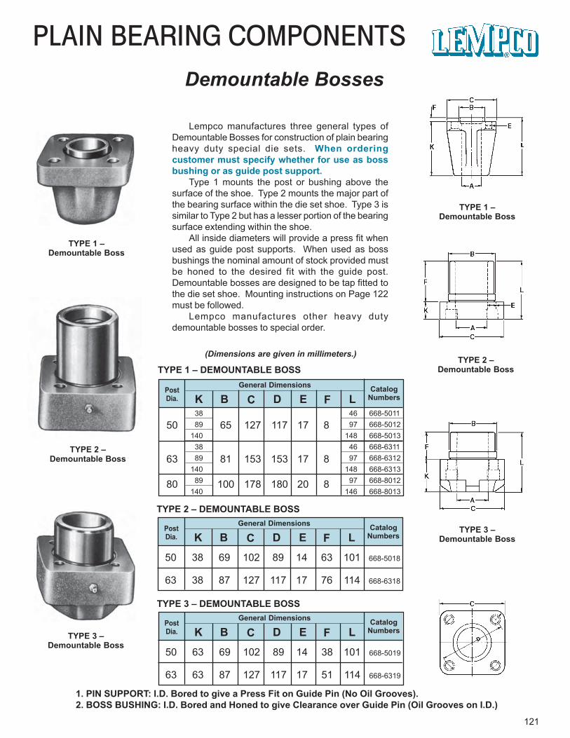
121
PLAIN BEARING COMPONENTSDemountable Bosses
TYPE 1 –Demountable Boss
TYPE 2 –Demountable Boss
TYPE 3 –Demountable Boss
TYPE 1 –Demountable Boss
TYPE 2 –Demountable Boss
TYPE 3 –Demountable Boss
1. PIN SUPPORT: I.D. Bored to give a Press Fit on Guide Pin (No Oil Grooves).2. BOSS BUSHING: I.D. Bored and Honed to give Clearance over Guide Pin (Oil Grooves on I.D.)
General Dimensions CatalogNumbers
PostDia. K B C D E F L
50 65 127 117 17 8
63 81 153 153 17 8
38 46 668-501189 97 668-5012
140 148 668-501338 46 668-631189 97 668-6312
140 148 668-631389 97 668-8012
140 146 668-8013
TYPE 1 – DEMOUNTABLE BOSS
TYPE 2 – DEMOUNTABLE BOSS
Lempco manufactures three general types ofDemountable Bosses for construction of plain bearingheavy duty special die sets. When orderingcustomer must specify whether for use as bossbushing or as guide post support.
Type 1 mounts the post or bushing above thesurface of the shoe. Type 2 mounts the major part ofthe bearing surface within the die set shoe. Type 3 issimilar to Type 2 but has a lesser portion of the bearingsurface extending within the shoe.
All inside diameters will provide a press fit whenused as guide post supports. When used as bossbushings the nominal amount of stock provided mustbe honed to the desired fit with the guide post.Demountable bosses are designed to be tap fitted tothe die set shoe. Mounting instructions on Page 122must be followed.
Lempco manufactures other heavy dutydemountable bosses to special order.
(Dimensions are given in millimeters.)
80 100 178 180 20 8
General Dimensions CatalogNumbers
PostDia. K B C D E F L
50 38 69 102 89 14 63 101 668-5018
63 38 87 127 117 17 76 114 668-6318
TYPE 3 – DEMOUNTABLE BOSSGeneral Dimensions Catalog
NumbersPostDia. K B C D E F L
50 63 69 102 89 14 38 101 668-5019
63 63 87 127 117 17 51 114 668-6319
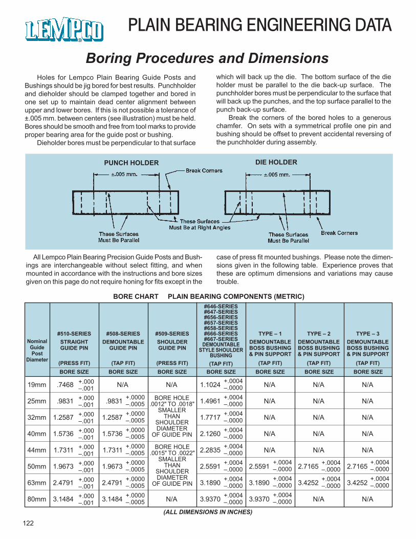
19mm .7468 N/A N/A 1.1024 N/A N/A N/A
25mm .9831 .9831 1.4961 N/A N/A N/A
32mm 1.2587 1.2587 1.7717 N/A N/A N/A
40mm 1.5736 1.5736 2.1260 N/A N/A N/A
44mm 1.7311 1.7311 2.2835 N/A N/A N/A
50mm 1.9673 1.9673 2.5591 2.5591 2.7165 2.7165
63mm 2.4791 2.4791 3.1890 3.1890 3.4252 3.4252
80mm 3.1484 3.1484 N/A 3.9370 3.9370 N/A N/A
PLAIN BEARING ENGINEERING DATA
122
Boring Procedures and DimensionsHoles for Lempco Plain Bearing Guide Posts and
Bushings should be jig bored for best results. Punchholderand dieholder should be clamped together and bored inone set up to maintain dead center alignment betweenupper and lower bores. If this is not possible a tolerance of±.005 mm. between centers (see illustration) must be held.Bores should be smooth and free from tool marks to provideproper bearing area for the guide post or bushing.
Dieholder bores must be perpendicular to that surface
All Lempco Plain Bearing Precision Guide Posts and Bush-ings are interchangeable without select fitting, and whenmounted in accordance with the instructions and bore sizesgiven on this page do not require honing for fits except in the
case of press fit mounted bushings. Please note the dimen-sions given in the following table. Experience proves thatthese are optimum dimensions and variations may causetrouble.
which will back up the die. The bottom surface of the dieholder must be parallel to the die back-up surface. Thepunchholder bores must be perpendicular to the surface thatwill back up the punches, and the top surface parallel to thepunch back-up surface.
Break the corners of the bored holes to a generouschamfer. On sets with a symmetrical profile one pin andbushing should be offset to prevent accidental reversing ofthe punchholder during assembly.
PUNCH HOLDER DIE HOLDER
BORE CHART PLAIN BEARING COMPONENTS (METRIC)
NominalGuidePost
Diameter
#510-SERIESSTRAIGHTGUIDE PIN
(PRESS FIT)
#508-SERIESDEMOUNTABLE
GUIDE PIN
(TAP FIT)
#509-SERIESSHOULDERGUIDE PIN
(PRESS FIT)
#646-SERIES#647-SERIES#656-SERIES#657-SERIES#658-SERIES#666-SERIES#667-SERIES
DEMOUNTABLESTYLE SHOULDER
BUSHING(TAP FIT)
TYPE – 1DEMOUNTABLEBOSS BUSHING& PIN SUPPORT
(TAP FIT)
TYPE – 2DEMOUNTABLEBOSS BUSHING& PIN SUPPORT
(TAP FIT)BORE SIZE BORE SIZE BORE SIZE BORE SIZE BORE SIZE BORE SIZE BORE SIZE
+.000–.001
+.0000–.0005
BORE HOLE.0012" TO .0018"
SMALLERTHAN
SHOULDERDIAMETER
OF GUIDE PIN
+.0004–.0000
+.0004–.0000
+.0004–.0000
+.000–.001+.000–.001+.000–.001+.000–.001+.000–.001+.000–.001+.000–.001
+.0000–.0005+.0000–.0005+.0000–.0005+.0000–.0005+.0000–.0005+.0000–.0005
+.0004–.0000
TYPE – 3DEMOUNTABLEBOSS BUSHING& PIN SUPPORT
(TAP FIT)
+.0004–.0000+.0004–.0000+.0004–.0000+.0004–.0000+.0004–.0000+.0004–.0000+.0004–.0000
BORE HOLE.0015" TO .0022"
SMALLERTHAN
SHOULDERDIAMETER
OF GUIDE PIN+.0004–.0000
+.0004–.0000
+.0004–.0000+.0004–.0000
(ALL DIMENSIONS IN INCHES)
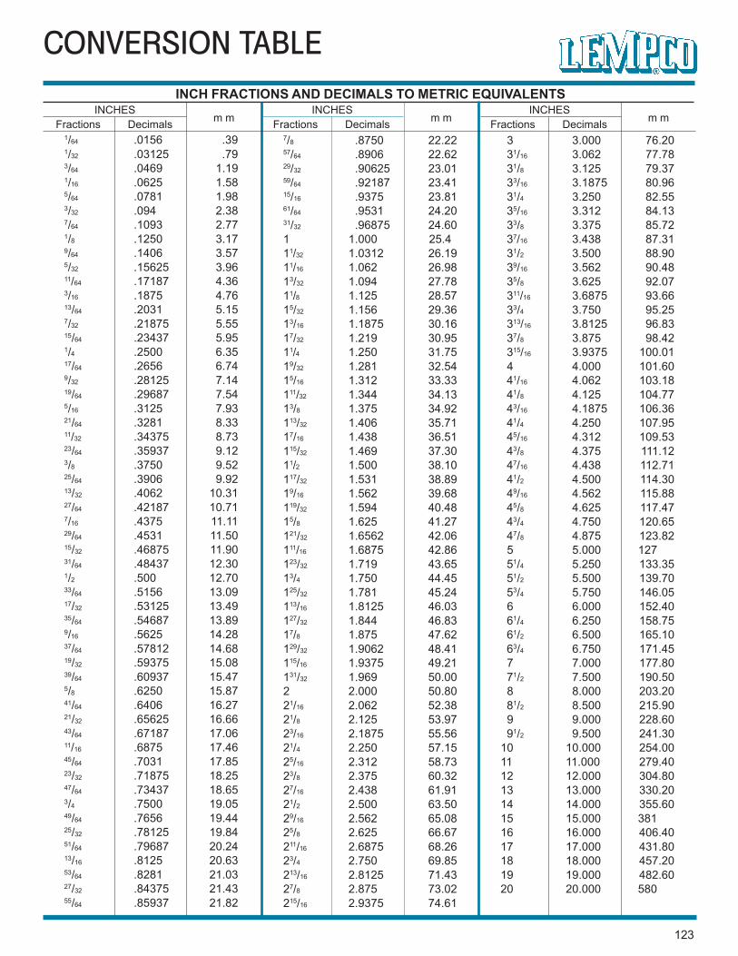
CONVERSION TABLEINCH FRACTIONS AND DECIMALS TO METRIC EQUIVALENTS
INCHESm mFractions Decimals
INCHESm mFractions Decimals
INCHESm mFractions Decimals
1/64 .0156 .391/32 .03125 .793/64 .0469 1.191/16 .0625 1.585/64 .0781 1.983/32 .094 2.387/64 .1093 2.771/8 .1250 3.179/64 .1406 3.575/32 .15625 3.9611/64 .17187 4.363/16 .1875 4.7613/64 .2031 5.157/32 .21875 5.5515/64 .23437 5.951/4 .2500 6.3517/64 .2656 6.749/32 .28125 7.1419/64 .29687 7.545/16 .3125 7.9321/64 .3281 8.3311/32 .34375 8.7323/64 .35937 9.123/8 .3750 9.5225/64 .3906 9.9213/32 .4062 10.3127/64 .42187 10.717/16 .4375 11.1129/64 .4531 11.5015/32 .46875 11.9031/64 .48437 12.301/2 .500 12.7033/64 .5156 13.0917/32 .53125 13.4935/64 .54687 13.899/16 .5625 14.2837/64 .57812 14.6819/32 .59375 15.0839/64 .60937 15.475/8 .6250 15.8741/64 .6406 16.2721/32 .65625 16.6643/64 .67187 17.0611/16 .6875 17.4645/64 .7031 17.8523/32 .71875 18.2547/64 .73437 18.653/4 .7500 19.0549/64 .7656 19.4425/32 .78125 19.8451/64 .79687 20.2413/16 .8125 20.6353/64 .8281 21.0327/32 .84375 21.4355/64 .85937 21.82
7/8 .8750 22.2257/64 .8906 22.6229/32 .90625 23.0159/64 .92187 23.4115/16 .9375 23.8161/64 .9531 24.2031/32 .96875 24.601 1.000 25.411/32 1.0312 26.1911/16 1.062 26.9813/32 1.094 27.7811/8 1.125 28.5715/32 1.156 29.3613/16 1.1875 30.1617/32 1.219 30.9511/4 1.250 31.7519/32 1.281 32.5415/16 1.312 33.33111/32 1.344 34.1313/8 1.375 34.92113/32 1.406 35.7117/16 1.438 36.51115/32 1.469 37.3011/2 1.500 38.10117/32 1.531 38.8919/16 1.562 39.68119/32 1.594 40.4815/8 1.625 41.27121/32 1.6562 42.06111/16 1.6875 42.86123/32 1.719 43.6513/4 1.750 44.45125/32 1.781 45.24113/16 1.8125 46.03127/32 1.844 46.8317/8 1.875 47.62129/32 1.9062 48.41115/16 1.9375 49.21131/32 1.969 50.002 2.000 50.8021/16 2.062 52.3821/8 2.125 53.9723/16 2.1875 55.5621/4 2.250 57.1525/16 2.312 58.7323/8 2.375 60.3227/16 2.438 61.9121/2 2.500 63.5029/16 2.562 65.0825/8 2.625 66.67211/16 2.6875 68.2623/4 2.750 69.85213/16 2.8125 71.4327/8 2.875 73.02215/16 2.9375 74.61
3 3.000 76.20 31/16 3.062 77.78 31/8 3.125 79.37 33/16 3.1875 80.96 31/4 3.250 82.55 35/16 3.312 84.13 33/8 3.375 85.72 37/16 3.438 87.31 31/2 3.500 88.90 39/16 3.562 90.48 35/8 3.625 92.07 311/16 3.6875 93.66 33/4 3.750 95.25 313/16 3.8125 96.83 37/8 3.875 98.42 315/16 3.9375 100.01 4 4.000 101.60 41/16 4.062 103.18 41/8 4.125 104.77 43/16 4.1875 106.36 41/4 4.250 107.95 45/16 4.312 109.53 43/8 4.375 111.12 47/16 4.438 112.71 41/2 4.500 114.30 49/16 4.562 115.88 45/8 4.625 117.47 43/4 4.750 120.65 47/8 4.875 123.82 5 5.000 127 51/4 5.250 133.35 51/2 5.500 139.70 53/4 5.750 146.05 6 6.000 152.40 61/4 6.250 158.75 61/2 6.500 165.10 63/4 6.750 171.45 7 7.000 177.80 71/2 7.500 190.50 8 8.000 203.20 81/2 8.500 215.90 9 9.000 228.60 91/2 9.500 241.3010 10.000 254.0011 11.000 279.4012 12.000 304.8013 13.000 330.2014 14.000 355.6015 15.000 38116 16.000 406.4017 17.000 431.8018 18.000 457.2019 19.000 482.6020 20.000 580
123

124
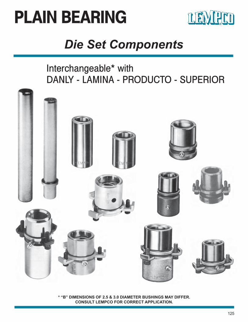
PLAIN BEARING
125
Die Set Components
Interchangeable* withDANLY - LAMINA - PRODUCTO - SUPERIOR
* “B” DIMENSIONS OF 2.5 & 3.0 DIAMETER BUSHINGS MAY DIFFER.CONSULT LEMPCO FOR CORRECT APPLICATION.
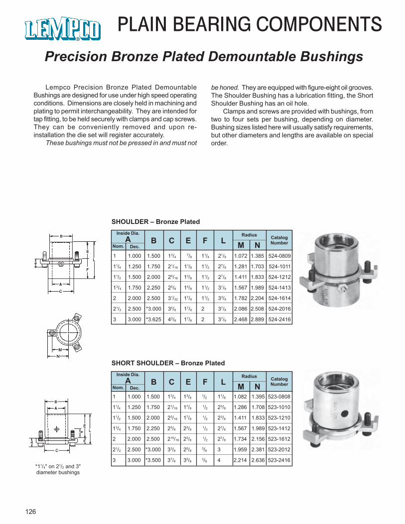
126
PLAIN BEARING COMPONENTSPrecision Bronze Plated Demountable Bushings
Lempco Precision Bronze Plated DemountableBushings are designed for use under high speed operatingconditions. Dimensions are closely held in machining andplating to permit interchangeability. They are intended fortap fitting, to be held securely with clamps and cap screws.They can be conveniently removed and upon re-installation the die set will register accurately.
These bushings must not be pressed in and must not
*11/4" on 21/2 and 3"diameter bushings
be honed. They are equipped with figure-eight oil grooves.The Shoulder Bushing has a lubrication fitting, the ShortShoulder Bushing has an oil hole.
Clamps and screws are provided with bushings, fromtwo to four sets per bushing, depending on diameter.Bushing sizes listed here will usually satisfy requirements,but other diameters and lengths are available on specialorder.
Inside Dia.A
Nom. Dec.
Radius CatalogNumberB C E F L M N
1 1.000 1.500 13/47/8 11/4 21/8 1.072 1.385 524-0809
11/4 1.250 1.750 21/16 11/8 11/2 27/8 1.281 1.703 524-1011
11/2 1.500 2.000 25/16 13/8 11/2 27/8 1.411 1.833 524-1212
13/4 1.750 2.250 25/8 15/8 11/2 31/8 1.567 1.989 524-1413
2 2.000 2.500 31/32 17/8 11/2 33/8 1.782 2.204 524-1614
21/2 2.500 *3.000 35/8 17/8 2 37/8 2.086 2.508 524-2016
3 3.000 *3.625 43/8 17/8 2 37/8 2.468 2.889 524-2416
SHOULDER – Bronze Plated
Inside Dia.A
Nom. Dec.
Radius CatalogNumberB C E F L M N
SHORT SHOULDER – Bronze Plated
1 1.000 1.500 13/4 13/8 1/2 17/8 1.082 1.395 523-0808
11/4 1.250 1.750 21/16 17/8 1/2 23/8 1.286 1.708 523-1010
11/2 1.500 2.000 25/16 17/8 1/2 23/8 1.411 1.833 523-1210
13/4 1.750 2.250 25/8 23/8 1/2 27/8 1.567 1.989 523-1412
2 2.000 2.500 215/16 23/8 1/2 27/8 1.734 2.156 523-1612
21/2 2.500 *3.000 33/8 25/8 3/8 3 1.959 2.381 523-2012
3 3.000 *3.500 37/8 35/8 3/8 4 2.214 2.636 523-2416
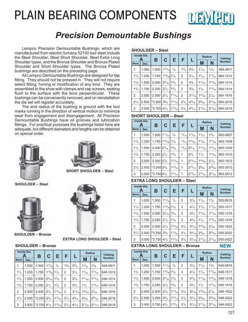
PLAIN BEARING COMPONENTS
127
Precision Demountable BushingsLempco Precision Demountable Bushings, which are
manufactured from electric furnace 52100 tool steel includethe Steel Shoulder, Steel Short Shoulder, Steel Extra LongShoulder types, and the Bronze Shoulder and Bronze PlatedShoulder and Short Shoulder types. The Bronze Platedbushings are described on the preceding page.
All Lempco Demountable Bushings are designed for tapfitting. They should not be pressed in. They will not requireselect fitting, honing or modification of any kind. They areassembled to the shoe with clamps and cap screws, seatingflush to the surface with the bore perpendicular. Thesebushings can be conveniently removed, and on reinstallationthe die set will register accurately.
The end radius of the bushing is ground with the toolmarks running in the direction of vertical motion to minimizewear from engagement and disengagement. All PrecisionDemountable Bushings have oil grooves and lubricationfittings. For practical purposes the bushings listed here areadequate, but different diameters and lengths can be obtainedon special order.
SHOULDER – Steel
SHORT SHOULDER – Steel
SHOULDER – Bronze
EXTRA LONG SHOULDER – Steel
1 1.000 1.500 111/16 7/8 13/4 25/8 11/16 13/8 548-0811
11/4 1.250 1.750 115/16 11/8 2 31/8 17/32 117/32 548-1013
11/2 1.500 2.000 23/16 13/8 2 33/8 111/32 121/32 548-1214
13/4 1.750 2.250 21/2 13/8 2 33/8 11/2 113/16 548-1414
2 2.000 2.500 27/8 113/16 2 313/16 145/64 21/64 548-1616
21/2 2.500 *3.250 35/8 113/16 21/2 45/16 25/64 225/64 548-2018
3 3.000 *3.750 41/8 113/16 21/2 45/16 211/32 221/32 548-2418
Inside Dia.A
Nom. Dec.
Radius CatalogNumberB C E F L M N
SHOULDER – Bronze
1 1.000 1.500 111/16 7/8 3 37/8 11/16 13/8 548-0816
11/4 1.250 1.750 115/16 11/8 3 41/8 17/32 117/32 548-1017
11/2 1.500 2.000 23/16 13/8 3 43/8 111/32 121/32 548-1218
13/4 1.750 2.250 21/2 13/8 3 43/8 11/2 113/16 548-1418
2 2.000 2.500 27/8 113/16 31/2 55/16 145/64 21/64 548-1622
21/2 2.500 3.250 35/8 113/16 31/2 55/16 25/64 225/64 548-2022
3 3.000 3.750 41/8 115/16 31/2 57/16 211/32 221/32 548-2422
Inside Dia.A
Nom. Dec.
Radius CatalogNumberB C E F L M N
EXTRA LONG SHOULDER – Bronze
SHOULDER – Bronze
1 1.000 1.500 111/16 7/8 3 37/8 11/16 13/8 555-0816
11/4 1.250 1.750 115/16 11/8 3 41/8 17/32 117/32 555-1017
11/2 1.500 2.000 23/16 13/8 3 43/8 111/32 121/32 555-1218
13/4 1.750 2.250 21/2 13/8 3 43/8 11/2 113/16 555-1418
2 2.000 2.500 27/8 113/16 31/2 55/16 145/64 21/64 555-1622
21/2 2.500 *3.250 35/8 113/16 31/2 55/16 25/64 225/64 555-2022
3 3.000 *3.750 41/8 115/16 31/2 57/16 211/32 221/32 555-2422
Inside Dia.A
Nom. Dec.
Radius CatalogNumberB C E F L M N
EXTRA LONG SHOULDER – Steel
1 1.000 1.500 111/16 7/8 13/16 111/16 11/16 13/8 563-0807
11/4 1.250 1.750 115/16 11/8 13/16 115/16 17/32 117/32 563-1008
11/2 1.500 2.000 23/16 13/813/16 23/16 111/32 121/32 563-1209
13/4 1.750 2.250 21/2 13/8 1 23/8 11/2 113/16 563-1410
2 2.000 2.500 27/8 113/16 1 213/16 145/64 21/64 563-1612
21/2 2.500 *3.250 35/8 113/16 1 213/16 25/64 225/64 563-2012
3 3.000 *3.750 41/8 113/16 1 213/16 211/32 221/32 563-2412
Inside Dia.A
Nom. Dec.
Radius CatalogNumberB C E F L M N
SHORT SHOULDER – Steel
1 1.000 1.500 111/16 7/8 13/4 25/8 11/16 13/8 564-0811
11/4 1.250 1.750 115/16 11/8 2 31/8 17/32 117/32 564-1013
11/2 1.500 2.000 23/16 13/8 2 33/8 111/32 121/32 564-1214
13/4 1.750 2.250 21/2 13/8 2 33/8 11/2 113/16 564-1414
2 2.000 2.500 27/8 113/16 2 313/16 145/64 21/64 564-1616
21/2 2.500 *3.250 35/8 113/16 21/2 45/16 25/64 225/64 564-2018
3 3.000 *3.750 41/8 113/16 21/2 45/16 211/32 221/32 564-2418
Inside Dia.A
Nom. Dec.
Radius CatalogNumberB C E F L M N
SHOULDER – Steel
NEW
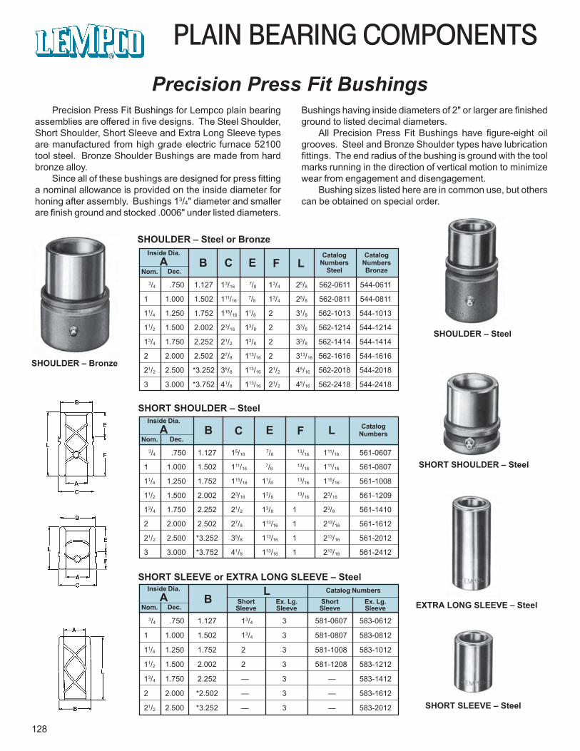
PLAIN BEARING COMPONENTS
128
Precision Press Fit BushingsPrecision Press Fit Bushings for Lempco plain bearing
assemblies are offered in five designs. The Steel Shoulder,Short Shoulder, Short Sleeve and Extra Long Sleeve typesare manufactured from high grade electric furnace 52100tool steel. Bronze Shoulder Bushings are made from hardbronze alloy.
Since all of these bushings are designed for press fittinga nominal allowance is provided on the inside diameter forhoning after assembly. Bushings 13/4" diameter and smallerare finish ground and stocked .0006" under listed diameters.
SHOULDER – Steel
SHORT SHOULDER – Steel
SHORT SLEEVE – Steel
EXTRA LONG SLEEVE – Steel
Bushings having inside diameters of 2" or larger are finishedground to listed decimal diameters.
All Precision Press Fit Bushings have figure-eight oilgrooves. Steel and Bronze Shoulder types have lubricationfittings. The end radius of the bushing is ground with the toolmarks running in the direction of vertical motion to minimizewear from engagement and disengagement.
Bushing sizes listed here are in common use, but otherscan be obtained on special order.
3/4 .750 1.127 13/16 7/8 13/4 25/8 562-0611 544-0611
1 1.000 1.502 111/16 7/8 13/4 25/8 562-0811 544-0811
11/4 1.250 1.752 115/16 11/8 2 31/8 562-1013 544-1013
11/2 1.500 2.002 23/16 13/8 2 33/8 562-1214 544-1214
13/4 1.750 2.252 21/2 13/8 2 33/8 562-1414 544-1414
2 2.000 2.502 27/8 113/16 2 313/16 562-1616 544-1616
21/2 2.500 *3.252 35/8 113/16 21/2 45/16 562-2018 544-2018
3 3.000 *3.752 41/8 113/16 21/2 45/16 562-2418 544-2418
Inside Dia.A
Nom. Dec.
CatalogNumbersBronze
B C E F L
SHOULDER – Steel or BronzeCatalog
NumbersSteel
3/4 .750 1.127 15/16 7/8 13/16 111/16 561-0607
1 1.000 1.502 111/16 7/8 13/16 111/16 561-0807
11/4 1.250 1.752 115/16 11/8 13/16 115/16 561-1008
11/2 1.500 2.002 23/16 13/8 13/16 23/16 561-1209
13/4 1.750 2.252 21/2 13/8 1 23/8 561-1410
2 2.000 2.502 27/8 113/16 1 213/16 561-1612
21/2 2.500 *3.252 35/8 113/16 1 213/16 561-2012
3 3.000 *3.752 41/8 113/16 1 213/16 561-2412
Inside Dia.A
Nom. Dec.B C E F L
SHORT SHOULDER – Steel
CatalogNumbers
3/4 .750 1.127 13/4 3 581-0607 583-0612
1 1.000 1.502 13/4 3 581-0807 583-0812
11/4 1.250 1.752 2 3 581-1008 583-1012
11/2 1.500 2.002 2 3 581-1208 583-1212
13/4 1.750 2.252 — 3 — 583-1412
2 2.000 *2.502 — 3 — 583-1612
21/2 2.500 *3.252 — 3 — 583-2012
Inside Dia.A
Nom. Dec.ShortSleeve
BL
SHORT SLEEVE or EXTRA LONG SLEEVE – SteelCatalog Numbers
Ex. Lg.Sleeve
ShortSleeve
Ex. Lg.Sleeve
SHOULDER – Bronze
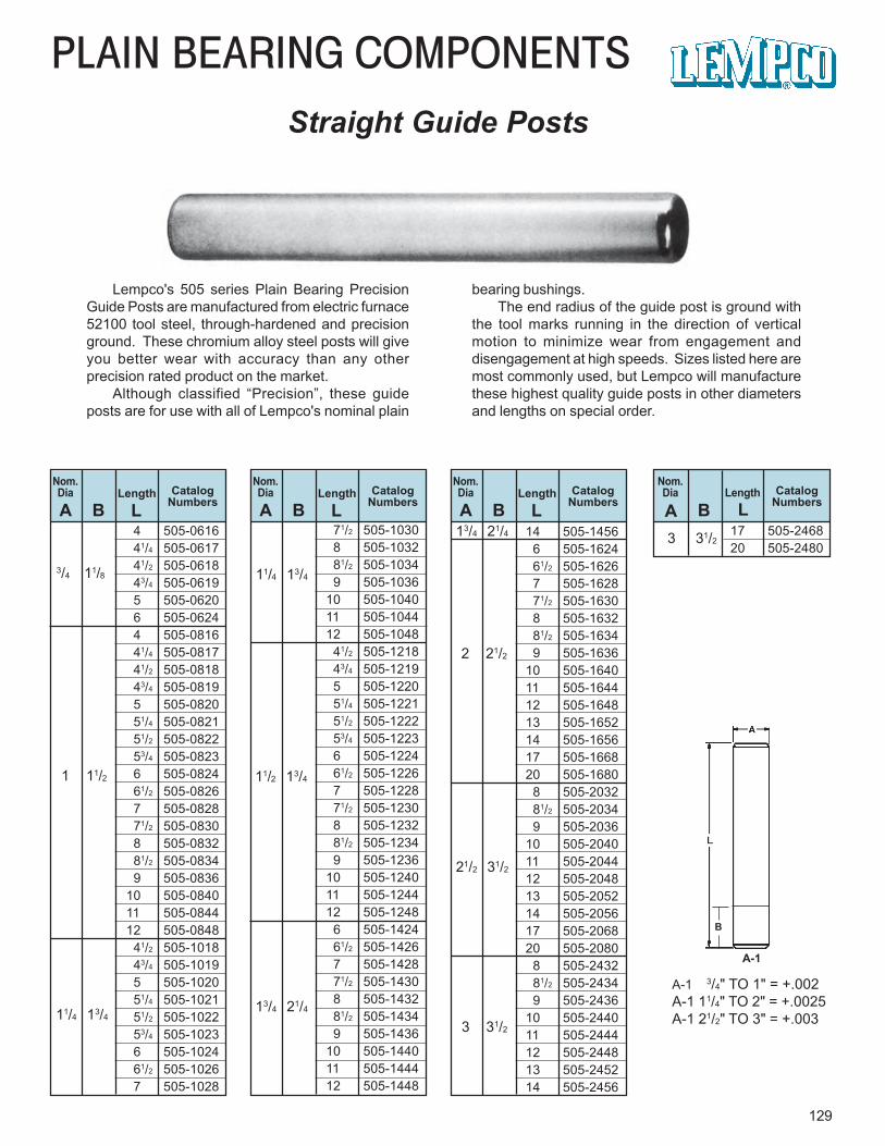
4 505-0616 41/4 505-0617 41/2 505-0618 43/4 505-0619 5 505-0620 6 505-0624 4 505-0816 41/4 505-0817 41/2 505-0818 43/4 505-0819 5 505-0820 51/4 505-0821 51/2 505-0822 53/4 505-0823 6 505-0824 61/2 505-0826 7 505-0828 71/2 505-0830 8 505-0832 81/2 505-0834 9 505-083610 505-084011 505-084412 505-0848 41/2 505-1018 43/4 505-1019 5 505-1020 51/4 505-1021 51/2 505-1022 53/4 505-1023 6 505-1024 61/2 505-1026 7 505-1028
129
PLAIN BEARING COMPONENTSStraight Guide Posts
Lempco's 505 series Plain Bearing PrecisionGuide Posts are manufactured from electric furnace52100 tool steel, through-hardened and precisionground. These chromium alloy steel posts will giveyou better wear with accuracy than any otherprecision rated product on the market.
Although classified “Precision”, these guideposts are for use with all of Lempco's nominal plain
bearing bushings.The end radius of the guide post is ground with
the tool marks running in the direction of verticalmotion to minimize wear from engagement anddisengagement at high speeds. Sizes listed here aremost commonly used, but Lempco will manufacturethese highest quality guide posts in other diametersand lengths on special order.
Nom.Dia Length Catalog
NumbersBLength Catalog
NumbersA LLA
3/4 11/8
1 11/2
11/4 13/4
Nom.Dia Length Catalog
NumbersB LA
Nom.Dia Length Catalog
NumbersB LA
2 21/2
3 31/2
11/4 13/4
11/2 13/4
13/4 21/4
B
A-1
13/4 21/4
21/2 31/2
71/2 505-1030 8 505-1032 81/2 505-1034 9 505-103610 505-104011 505-104412 505-1048 41/2 505-1218 43/4 505-1219 5 505-1220 51/4 505-1221 51/2 505-1222 53/4 505-1223 6 505-1224 61/2 505-1226 7 505-1228 71/2 505-1230 8 505-1232 81/2 505-1234 9 505-123610 505-124011 505-124412 505-1248 6 505-1424 61/2 505-1426 7 505-1428 71/2 505-1430 8 505-1432 81/2 505-1434 9 505-143610 505-144011 505-144412 505-1448
14 505-1456 6 505-1624 61/2 505-1626 7 505-1628 71/2 505-1630 8 505-1632 81/2 505-1634 9 505-163610 505-164011 505-164412 505-164813 505-165214 505-165617 505-166820 505-1680 8 505-2032 81/2 505-2034 9 505-203610 505-204011 505-204412 505-204813 505-205214 505-205617 505-206820 505-2080 8 505-2432 81/2 505-2434 9 505-243610 505-244011 505-244412 505-244813 505-245214 505-2456
17 505-246820 505-2480
Nom.Dia
B3 31/2
A-1 3/4" TO 1" = +.002A-1 11/4" TO 2" = +.0025A-1 21/2" TO 3" = +.003
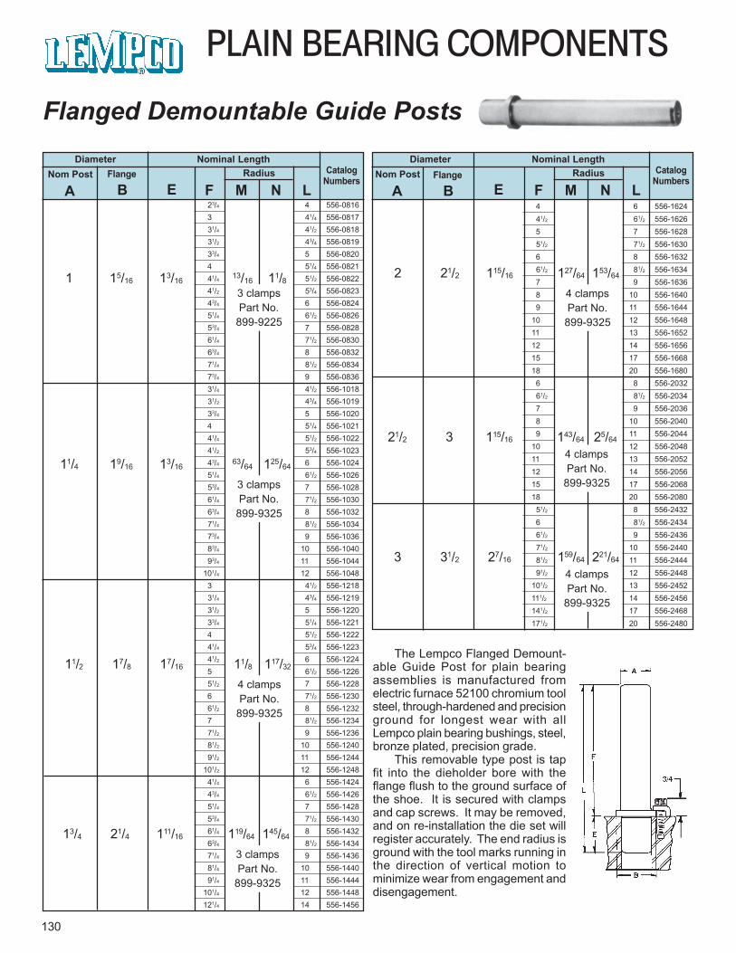
4 6 556-1624 41/2 61/2 556-1626 5 7 556-1628 51/2 71/2 556-1630 6 8 556-1632 61/2 81/2 556-1634 7 9 556-1636 8 10 556-1640 9 11 556-164410 12 556-164811 13 556-165212 14 556-165615 17 556-166818 20 556-1680 6 8 556-2032 61/2 81/2 556-2034 7 9 556-2036 8 10 556-2040 9 11 556-204410 12 556-204811 13 556-205212 14 556-205615 17 556-206818 20 556-2080 51/2 8 556-2432 6 81/2 556-2434 61/2 9 556-2436 71/2 10 556-2440 81/2 11 556-2444 91/2 12 556-2448101/2 13 556-2452111/2 14 556-2456141/2 17 556-2468171/2 20 556-2480
23/4 4 556-0816 3 41/4 556-0817 31/4 41/2 556-0818 31/2 43/4 556-0819 33/4 5 556-0820 4 51/4 556-0821 41/4 51/2 556-0822 41/2 53/4 556-0823 43/4 6 556-0824 51/4 61/2 556-0826 53/4 7 556-0828 61/4 71/2 556-0830 63/4 8 556-0832 71/4 81/2 556-0834 73/4 9 556-0836 31/4 41/2 556-1018 31/2 43/4 556-1019 33/4 5 556-1020 4 51/4 556-1021 41/4 51/2 556-1022 41/2 53/4 556-1023 43/4 6 556-1024 51/4 61/2 556-1026 53/4 7 556-1028 61/4 71/2 556-1030 63/4 8 556-1032 71/4 81/2 556-1034 73/4 9 556-1036 83/4 10 556-1040 93/4 11 556-1044101/4 12 556-1048 3 41/2 556-1218 31/4 43/4 556-1219 31/2 5 556-1220 33/4 51/4 556-1221 4 51/2 556-1222 41/4 53/4 556-1223 41/2 6 556-1224 5 61/2 556-1226 51/2 7 556-1228 6 71/2 556-1230 61/2 8 556-1232 7 81/2 556-1234 71/2 9 556-1236 81/2 10 556-1240 91/2 11 556-1244101/2 12 556-1248 41/4 6 556-1424 43/4 61/2 556-1426 51/4 7 556-1428 53/4 71/2 556-1430 61/4 8 556-1432 63/4 81/2 556-1434 71/4 9 556-1436 81/4 10 556-1440 91/4 11 556-1444101/4 12 556-1448121/4 14 556-1456
PLAIN BEARING COMPONENTS
130
Flanged Demountable Guide Posts
11/4 19/16 13/1663/64 125/64
Diameter Nominal LengthCatalog
NumbersRadiusNom Post Flange
A B E F M N L
Diameter Nominal LengthCatalog
NumbersRadiusNom Post Flange
A B E F M N L
The Lempco Flanged Demount-able Guide Post for plain bearingassemblies is manufactured fromelectric furnace 52100 chromium toolsteel, through-hardened and precisionground for longest wear with allLempco plain bearing bushings, steel,bronze plated, precision grade.
This removable type post is tapfit into the dieholder bore with theflange flush to the ground surface ofthe shoe. It is secured with clampsand cap screws. It may be removed,and on re-installation the die set willregister accurately. The end radius isground with the tool marks running inthe direction of vertical motion tominimize wear from engagement anddisengagement.
1 15/16 13/1613/16 11/83 clampsPart No.
899-9225
3 clampsPart No.
899-9325
11/2 17/8 17/16 11/8 117/32
4 clampsPart No.
899-9325
13/4 21/4 111/16 119/64 145/64
3 clampsPart No.
899-9325
2 21/2 115/16 127/64 153/64
4 clampsPart No.
899-9325
21/2 3 115/16 143/64 25/64
4 clampsPart No.
899-9325
3 31/2 27/16 159/64 221/64
4 clampsPart No.
899-9325

NITROGEN GAS SPRINGS
131
High ForceLong LifeHigh Cycle RateLempco offers 20 unique models with strokesranging from 6mm/.24" to 300mm/11.8" and initialcontact forces from 15.0 lbs. to 41,000 lbs.
If you are designing a new product, or makingimprovements to an existing one, a Raymond orKaller nitrogen gas spring may be the answer. CallLempco for technical assistance to discuss newapplication ideas. Current applications includevalve actuators, shock absorbing bumpers,mountain bike suspension, etc.
If your application calls for a custom spring suchas a special stroke length, shorter overall length,smaller diameter, high cycle rates or otherdifferentiating specifications, call our technicalassistance department and let us customize aspring or spring system for you.
Technical Features:• High initial force• Low force increase through stroke• Pressure medium: Nitrogen gas• Range of operating temperature: -25° F
to 180° F• Maximum piston rod speed:
35 meters/min 115 ft/min• Component type mounting fixtures• Manufacturer is ISO 9001 certified• Strict testing and quality control
Call us at 1 (800) 321-8632 or fax at 1 (800) 221-6310 for our complete catalog of specifications.Ask for Heavy Duty Gas Spring Catalog, FormR100.
Visit our Web Site at www.lempco.com
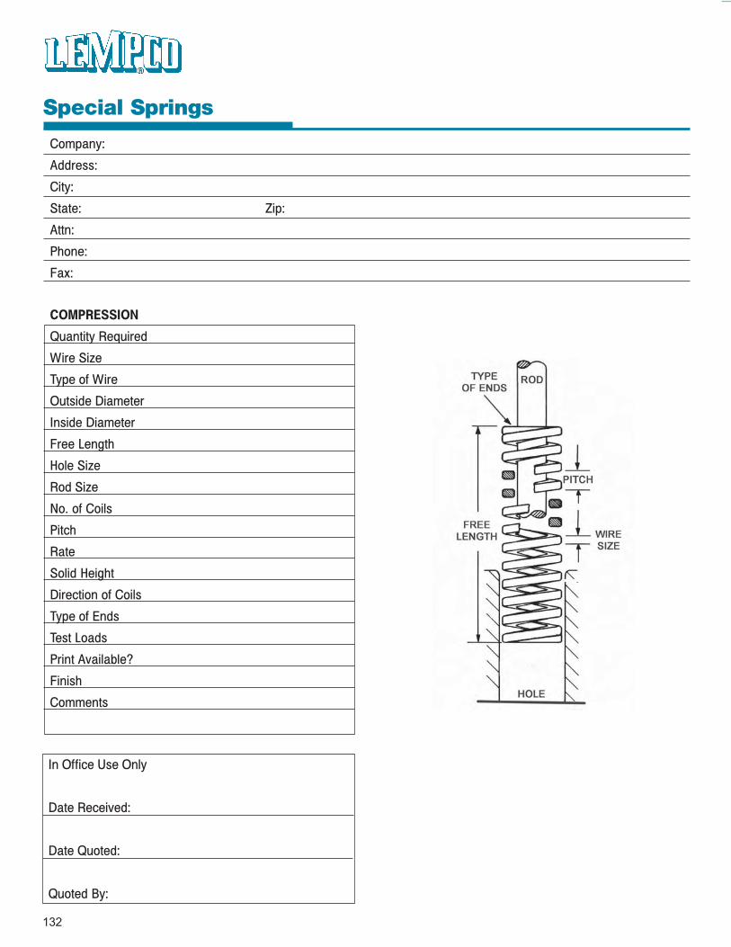
132
Special Springs
Company:
Address:
City:
State: Zip:
Attn:
Phone:
Fax:
In Office Use Only
Date Received:
Date Quoted:
Quoted By:
COMPRESSION
Quantity Required
Wire Size
Type of Wire
Outside Diameter
Inside Diameter
Free Length
Hole Size
Rod Size
No. of Coils
Pitch
Rate
Solid Height
Direction of Coils
Type of Ends
Test Loads
Print Available?
Finish
Comments
133
Alphabetical Index
Product Page Numbers
Bolsters And Steel Plate 67 - 74Bolsters - Small Press 68 - 69Bolsters - Large Press 70 - 73J.I.C. Pressroom Standards 69, 70 - 73Machined Steel Plate 74
C.A.D. E-Mail Instructions 41
Components - Die Set - Inch 79 - 102Ball Bearing - Rotainer/Retainers/Bushings/Guide Posts 80 - 88Ball Bearing - Engineering Data 89 - 91Plain Bearing - Bushings/Guide Posts/Demountable Bosses 92 - 100Plain Bearing - Engineering Data 101 - 102
Components - Die Set - Interchangeable/Plain Bearing(Danly/Lamina/Producto/Superior) 125 - 130
Bushings - Precision Demountable/Press Fit 126 - 128Guide Posts - Straight/Flanged Demountable 129 - 130
Components - Die Set - Metric 103 - 112, 117 - 122Ball Bearing - Rotainer/Retainers/Guide Posts/Bushings 104 - 110Ball Bearing - Engineering Data 111 - 112Conversion Table 123Plain Bearing - Bushings/Guide Posts/Demountable Bosses 117 - 121Plain Bearing - Engineering Data 122
Customized Guidance System 75 - 77
134
Alphabetical Index
Product Page Numbers
Die SetsAluminum 66Flanged Two Post - Ball Bearing/Plain Bearing/ Precision 1 - 7Forming Machine - Dovetail Sets for Multi-Slide/Verti-Slide/Fourslide Machines 59 - 65Metric - Ball & Plain Bearing All-Steel 113 - 116Rectangular Four Post - Ball Bearing/Plain Bearing/Precision 21 - 35Rectangular Two Post - Ball Bearing/Plain Bearing/Precision 9 - 19Special - Large All-Steel Ball & Plain Bearing 43 - 49
Demountable Boss All-Steel Ball & Plain Bearing 50 - 51 Round All-Steel Ball & Plain Bearing 52 Long Narrow All-Steel Ball & Plain Bearing 53 Heavy-Duty All-Steel Ball & Plain Bearing 54 - 57
Factors In Die Set Design I - III
Lempcoshank 37 - 40
Lubrication Instructions For Ball Assembly 78
Pressure Control DevicesNitrogen Gas Springs 131Special Springs Worksheet 132

LempcoIndustriesThe GlobalStandardWith DistributorsLocated Worldwide