Embed Size (px)
Citation preview

ORIGINAL ARTICLE
Dielectric Elastomer Spring-Roll Bending Actuators:Applications in Soft Robotics and Design
Jinrong Li,1 Liwu Liu,2 Yanju Liu,2 and Jinsong Leng1
Abstract
Soft robotics is an emerging area that attracts more and more attention. The intrinsic flexibility and complianceof soft materials and structures would endow novel functions with soft robots. Dielectric elastomers coulddeform sustainably subjected to external electrical stimuli and become promising materials for soft robots dueto the large actuation strain, low elastic modulus, fast response, and high energy density. This article focuses onthe fabrication, applications, and design of the dielectric elastomer spring-roll bending actuators. The actuatorwith large electrically induced bending angle has been made and demonstrated the applications in flexiblegripper and inchworm-inspired soft crawling robot. The basic performance of the gripper and the crawling robothas been characterized. Furthermore, a thermodynamic model has been established to investigate the defor-mation and failure of such actuators. Comparison between theoretical and test results shows that the model issuitable for the prediction of the performance of the actuator. Then the influence of some design parameters onthe performance of the actuator has been analyzed and discussed based on the model. The results could provideguidance to the design and optimization of such actuators for different applications.
Keywords: dielectric elastomer, soft robots, thermodynamic model, actuator design
Introduction
Soft robotics is an emerging area inspired by softanimals in nature, and the development of soft robots
highly relies on the advances of soft materials or flexiblestructures.1–3 Variable soft robots have been designed andfabricated based on pneumatic actuation,4–9 shape memorymaterials10–14 electroactive polymers,15–22 liquid metals,23
and so on. Compared with traditional robots built with hardmaterial, soft robots have the advantages of lighter weight,larger continuum deformation, and better adaptivity tocomplex environments. The intrinsic flexibility and compli-ance of soft materials not only simplify or minimize the robotstructures but also make the soft robots possess some specialfeatures that are hard to be realized in traditional robots, suchas self-healing,24 growth,9,25 and movements through gaps orconstrained environment.5,9
Dielectric elastomers are typical electroactive polymersthat can response to external electrical stimuli. Normally, it isa sandwiched structure composed of one elastomer film layerand compliant electrodes on two opposite surfaces.26 Sub-
jected to external electric field, a dielectric elastomer wouldreduce its thickness and enlarge its area due to Maxwellstress. The large actuation strain, fast response, and high-energy density make dielectric elastomer a promising mate-rial for soft robots.27 Various types of actuators have beenfabricated based on dielectric elastomers and have demon-strated applications in walking robots,15–17 wrestling ro-bots,28 facial expression,29 tunable lens,30 grippers,18,19,31
airship,32 active hinges,33 and so on.In this article, we focus on the fabrication, applications,
and design of dielectric elastomer spring-roll bending actu-ator. Slightly different from the spring-roll actuators withmultiple degrees-of-freedom,15 only the film parts in onsideof our bending actuator are active to achieve a larger bendingangle with the sacrifice of the multiple degrees-of-freedommovement, since the circumferential angle of the coatedcompliant electrodes could be larger than p. It may also re-duce the complexity in fabrication and control for someapplications where one directional bending is required. Theflexible gripper and inchworm-inspired crawling robothave been fabricated based on such actuators as possible
1Center for Composite Materials and Structures, Harbin Institute of Technology, Harbin, China.2Department of Astronautical Science and Mechanics, Harbin Institute of Technology, Harbin, China.
SOFT ROBOTICSVolume 6, Number 1, 2019ª Mary Ann Liebert, Inc.DOI: 10.1089/soro.2018.0037
69
Dow
nloa
ded
by H
arbi
n In
dust
rial
Uni
vers
ity f
rom
ww
w.li
eber
tpub
.com
at 0
2/29
/20.
For
per
sona
l use
onl
y.

applications in soft robotics and their basic performance hasbeen characterized. Furthermore, a thermodynamic modelhas also been established to theoretically investigate the de-formation and failure of the spring-roll bending actuator. Onthe basis of this model, the influences of some design pa-rameters on the actuator performance have been analyzed anddiscussed. That will provide the guidance for the design andoptimization of the dielectric elastomer spring-roll actuatorfor different practical applications.
Dielectric Elastomer Spring-Roll Bending Actuatorand Its Applications in Soft Robotics
Fabrication and performance of the spring-rollbending actuators
The dielectric elastomer spring-roll actuator is composedof a compressed spring as the core, a stretched dielectricelastomer film (VHB 4910 produced by 3M Company)wrapping around the spring, carbon grease (produced by MGChemicals) as compliant electrodes coated only on the filmparts at one side of the actuator, and two caps to prevent thespring from slipping or protruding due to the restoring forceand viscosity of VHB tape.
The fabrication process of the spring-roll bending actuatoris illustrated in Figure 1 and described as follows. (1) Thespring is precompressed using the caps and supportingstructure, which will be taken out after the fabrication. Theprecompression of spring could maintain a higher longitu-dinal prestretch ratio of the VHB film. (2) The VHB film isbiaxial prestretched and only the central part of film that hasmore uniform prestretch will be used. (3) The carbon greasewas coated on the prestretched film using a mask to formrectangular electrodes with calculated distances to ensurethat the electrodes could stack at one side of the actuator.Each electrode is connected to a copper wire for applyinghigh voltage. The wires connected to adjacent electrodeshave opposite directions and are connected to the high volt-age and ground, respectively. The number of electrodes couldbe altered based on different requirements or design. (4) Theprecompressed spring (with the supporting structure) is rolledover the coated VHB film to let the film wrap around thespring and finally the supporting structure is taken out.
The resulted spring-roll bending actuator and its perfor-mance are shown in Figure 2 and Supplementary Video S1. In
Supplementary Video S1, the actuator acted in the form of acantilever beam with one end fixed by the clamp and the ap-plied voltage rose from 2 to 6 kV. The actuator failed when theapplied voltage is 6 kV.
Flexible gripper
Based on the electrically induced bending deformation ofthis kind of actuator, some applications in soft robotics havebeen explored. With the help of 3D printing technology, wehave designed and fabricated a three-finger flexible gripperthat is composed of 3D-printed structures and three spring-roll bending actuators. Each actuator has an effective lengthof about 5 mm and weight of around 11 g. The actuators areelectrically connected in parallel and the control wires aretethered to the gripper and hide inside the 3D-printed struc-tures to prevent danger of high voltage to human body. Therest and grasping states of the gripper are demonstrated inFigure 3. Supplementary Video S2 shows the gripper graspedan object and released it into a box incorporated with a re-motely controlled toy crane truck.
To evaluate the performance of the flexible gripper, themaximum pull-out force under different input voltages wastested. The gripper first grasped a container and then thewater was added drop by drop until the container fell fromthe gripper (Supplementary Video S3). The pull-out forcewas calculated from the maximum gross weight of thecontainer and water. It should be noted that the pull-outforce is determined by the shape and size of the graspedobject and also the adhesion or friction between the objectand gripper.
In this study, the container we used is cut from a bottle andits maximum radius is close to that of the inner circle of thegripper. Also, each end of the actuator was wrapped by heatshrink tubing with smooth surface to avoid adhesion betweenthe VHB tape and container since that adhesion may generateuncertainty of results. The measured pull-out force was171.5, 193.7, and 228.3 mN when the applied voltage is 4,4.5, and 5 kV, respectively. The pull-out force would rise ifsticky or rough surface was put on the end of each actuator toprovide higher friction. The gripper should have higher pull-out force under higher applied voltage. In fact, it could graspthe container at a higher voltage such as 5.5 kV. However,one of the actuators would fail before we obtain a reliableresult when that voltage is applied for quite a long time.
FIG. 1. Schematic of the fabrication process of the dielectric elastomer spring-roll actuator.
70 LI ET AL.
Dow
nloa
ded
by H
arbi
n In
dust
rial
Uni
vers
ity f
rom
ww
w.li
eber
tpub
.com
at 0
2/29
/20.
For
per
sona
l use
onl
y.

Inchworm-inspired crawling robots
The bending and unbending of the spring-roll actuator aresimilar to the deformation of some mollusks. So here we alsodemonstrate an inchworm-inspired crawling robot based onthis kind of actuator. The structure of this crawling robot isquite simple and consists of a spring-roll actuator and two endcaps (Fig. 4). There are two bundles of oriented plastic fibersat the bottom of each end cap to provide anisotropic frictionso that the robot could move forward on surfaces that is nottoo smooth, such as paper, when a sinusoidal high voltage isapplied. The spring used in this crawling robot is longer thanthat used in the flexible gripper since the buckling of thespring could make the actuator curved so that it is easier torealize the anisotropic friction.
The applied voltage is generated from a functional wave-form generator and amplified (1000 times) by a high-voltageamplifier (Trek Model 10/40A). The actuator should havelarger deformation at lower input voltage frequency in principle.
However, the gravity force and friction force between theoriented fibers and bottom surface would reduce the defor-mation of the actuator. Thus, the speed of the crawling robotat low frequency of input voltage is lower than that at higherfrequency. On the contrary, when the input voltage frequencyis too high, the crawling robot will oscillate severely withrandom moving direction rather than crawling forward. Thesuitable frequency interval would be 10–20 Hz from our test(Supplementary Videos S4 and S5). The tested crawlingspeed of the robot is 15, 22.5, and 26.3 mm/s, respectively,when the applied voltage has amplitude of 0–6 kV and fre-quency of 10, 15, and 20 Hz.
Model of the Actuator
Model establishment
For better understanding and optimization of the spring-roll actuator, the following part of this article focuses on the
FIG. 2. The shape of the spring-rollbending actuator when (a) no voltageis applied and (b) the applied voltageis 6 kV.
FIG. 3. Photos of the three-finger flexible gripper (a) in rest state, (b) grasping object, and (c) in grasping state without object.
DIELECTRIC ELASTOMER SPRING-ROLL BENDING ACTUATORS 71
Dow
nloa
ded
by H
arbi
n In
dust
rial
Uni
vers
ity f
rom
ww
w.li
eber
tpub
.com
at 0
2/29
/20.
For
per
sona
l use
onl
y.

modeling and design of this kind of actuator. The actuator isregarded as a thermodynamic system that consists of com-pressed spring and multilayer stretched film. The compliantelectrodes are assumed to have no stiffness and only deter-mine which layer is active. Actually, all layers at the activeside of the actuator besides the innermost and outermostlayers are active since both surfaces of such layers are coatedwith carbon grease. First, we illustrate the definitions of someparameters in the actuator. The circumferential angles of boththe active area and inactive area are assumed to be equal to p,representing an ideal state. Although from the same film, theactive and inactive areas are regarded as two separate partssince the dielectric energy of only the active area will beconsidered. Figure 5a shows the dimension changes of thespring and innermost layer during the fabrication process.
The cross section of the spring used is circle and the freelength, outside radius, and wire diameter of the spring aredenoted by L0, r, and d, respectively. The precompressionratio ks represents the ratio of the length of spring after pre-compression over its initial length. The VHB films in theactive and inactive area have stretch ratios in two directionsof k1, k2, and k¢
1, k¢2, respectively, and the innermost layer of
the actuator has a dimension of L1 · L2 · L3 at reference state.In the prestretch state, we have k1¼ k¢
1¼ k1p andk2¼ k¢
2¼ k2p. From the geometrical relationships, we canobtain that
k1p L1¼ ksL0, (1)
k2p L2¼ pr: (2)
As described before, there are totally N + 2 layers in anactuator with N active layers. We number each layer from 0 toN + 1 as shown in Figure 5b. The thickness of the prestretchedfilm is L3
�k1pk2p, in which L3 is also the thickness of VHB
tape and is denoted by d0. Then for the n-th layers, the cir-cumferential geometrical relationship becomes
k2pL2(n)¼ p rþ nd0
k1pk2p
� �, (3)
or
L2(n)¼ L2(1þ nd0
rk1pk2p
); (4)
where the terms in the bracket could not be neglected espe-cially when n is large since d0 and r are in the same order.
Then we analyze the deformation of the actuator underexternal load. The parameters defined so far are corre-sponding to the state that the supporting structure is not takenout when fabrication. After the supporting structure is takenout, the system will reach a new equilibrium. The deforma-tion in this process is called initial deformation in this article.The initial deformation will determine the final length of theactuator. In most cases, the actuator will further elongate orcontract in this process and the longitudinal stretch ratios ofthe film on both sides are uniform. In the final state afterinitial deformation, we would have k1¼ k¢
1¼ k1i.The circumferential stretch of the film is restrained by the
spring and the adhesion between inactive layers. The cir-cumferential deformation of the outmost active layer is nottoo large as can be seen from Supplementary Video S1. So thedielectric elastomer film is assumed to be in pure shear state34
for simplification. Then the equation k2¼ k¢2¼ k2p holds in
both initial deformation and bending deformation. When theexternal voltage is applied, the active layers will expand inlongitudinal direction so that the actuator will bend. Thelongitudinal stretches will be determined by the angular po-sition and also the bending angle of the actuator. That willresult in implicit equations. To avoid complexity in solvingimplicit equations, here we take the assumption that thelongitudinal stretch is uniform in each layer, which is similarto the stroke assumption mentioned in Pei et al.15 Althoughinducing inaccuracies in results, such simplification is stillvalid in investigating the influences of design parameters onthe performance of the actuator.
FIG. 4. Photo of theinchworm-inspired crawlingrobot.
72 LI ET AL.
Dow
nloa
ded
by H
arbi
n In
dust
rial
Uni
vers
ity f
rom
ww
w.li
eber
tpub
.com
at 0
2/29
/20.
For
per
sona
l use
onl
y.

During the bending deformation, for the spring, theequivalent mechanical load is an axial tensile force P and abending moment M in this condition, as shown in Figure 5c.Thus, the final deformation of the actuator is the superposi-tion of elongation and pure bending. Based on the abovediscussion, the bending process of the actuator is described asfollows concerning the stretch ratio changes of the innermostlayers, and illustrated in Figure 5d. The longitudinal stretchratios of the active and inactive parts change from k1i to k1m
first and then become k1b and k¢1b, respectively, when the
bending angle is h. In Supplementary Video S1, the pitch ofthe compressed spring in the inactive part, which is trans-parent, has no obvious change when it bends. Then we havek¢
1b¼ k1i and the geometrical relationship of k1m, k1b, k¢1b, and
h becomes
k1m¼k1bþ k¢
1b
2, (5)
h¼ k1b� k1ið ÞL1
2r: (6)
For the n-th layer, the longitudinal stretch ratio is written asfollows:
k1(n)¼ k1(1þ nd0
Rþ rð Þk1pk2p
), (7)
where R is the curvature radius of the actuator. The calcu-lation results show that R is more than 50 times of d0 even
when the bending angle is more than 90�. So we can just takek1(n)¼ k1 for approximation when n is less than 20 (thisvalue could be larger if VHB4905 is used).
The ideal dielectric elastomer model, which has beenused almost exclusively to analyze the dielectric elasto-mers and their actuators,35–38 is utilized as the materialmodel and the incompressible neo-Hookean model is usedto describe the nonlinear mechanical behavior of the VHB.The spring is assumed to be linearly elastic since the force/displacement curve of the spring remains linear even whenthe spring is compressed by 50%.
Then we can formulate the Helmholtz free energy of thewhole system. It is the function of two generalized coordi-nates, the longitudinal stretch of the innermost layer in theactive part k1 and the charge Q in one electrode of the firstactive layer. k¢
1will also appear in the expression of the
Helmholtz free energy, but it is not independent based on theaforementioned discussion and thus could not be regarded asthe generalized coordinate. All the active layers could beregarded as compliant capacitors that connected in paralleland have the same dielectric energy density. If the positivecharge on the first active layer is Q, the positive charge on then-th layer would be QL2(n)=L2. Then the dielectric energy ofthe n-th layer is
Ee(n)¼1
2eQ
k1L1k2pL2
� �2
L1L2(n)L3: (8)
Thus, the Helmholtz free energy of the whole system iswritten as follows:
FIG. 5. (a) Dimensionchanges of the dielectric elas-tomer film after prestretch andthe spring after precompres-sion; (b) schematic of thenumber of each layer inwhich the thick lines repre-sent the active layers thatwere coated with electrodeson both sides and the finelines represent the inactivelayers; (c) equivalent loadingstate of the actuator when theexternal voltage is applied;(d) illustration of the super-position of the bending ac-tuation of the actuator andgeometric parameter changein this process.
DIELECTRIC ELASTOMER SPRING-ROLL BENDING ACTUATORS 73
Dow
nloa
ded
by H
arbi
n In
dust
rial
Uni
vers
ity f
rom
ww
w.li
eber
tpub
.com
at 0
2/29
/20.
For
per
sona
l use
onl
y.
where Es is the elastic energy stored in the spring. Considerthat the system is in equilibrium under axial tensile force P,external bending moment M, and applied voltage F. Thechange of free energy is attributed to the work done by me-chanical load and electrical load. For any small change indeformation or charge, we have
dH¼PL1dk1þMdhþ +N
n¼ 1
1þ nd0
rk1pk2p
� �FdQ: (10)
From Equation (6), h is the function of k1 and thus Equa-tion (10) is rewritten as follows:
dH¼ Pþ M
2r
� �L1dk1þ +
N
n¼ 1
1þ nd0
rk1pk2p
� �FdQ: (11)
Taking k1 and Q as the generalized coordinates, the gen-eralized mechanical load and the generalized electrical loadare the partial derivatives of free energy. That is,
Pþ M
2r¼ qH(k1, Q)
L1qk1
, (12)
and
F¼ qH(k1, Q)
+N
n¼ 1
1þ nd0
rk1pk2p
, (13)
where PþM=2rð Þ and F are the generalized mechanical andelectrical loads, respectively. Equations (12) and (13) are thestate equations of the system and thus we can analyze thedeformation of the actuator.
Initial deformation
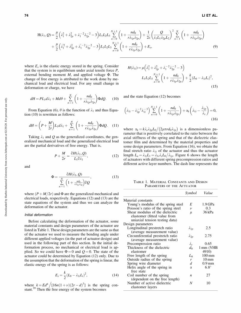
Before calculating the deformation of the actuator, somematerial constants and design parameters of the actuator arelisted in Table 1. These design parameters are the same as thatof the actuator we used to measure the bending angle underdifferent applied voltages (in the part of actuator design) andused in the following part of this section. In the initial de-formation process, no mechanical or electrical load is ap-plied. So we could have F¼ 0 and Q¼ 0. The state of theactuator could be determined by Equation (12) only. Due tothe assumption that the deformation of the spring is linear, theelastic energy of the spring is as follows:
Es¼k
2L0� k1iLið Þ2, (14)
where k¼Ed4.
[16n 1þ �ð Þ 2r� dð Þ3] is the spring con-stant.39 Then the free energy of the system becomes
H(k1i)¼l k21þ k2
2pþ k� 21 k� 2
2p � 3� �
L1L2L3 +Nþ 1
n¼ 0
1þ nd0
rk1pk2p
� �þ k
2L0� k1iLið Þ2,
(15)
and the state Equation (12) becomes
k1i� k� 22p k� 3
1i
� �+
Nþ 1
n¼ 0
1þ nd0
rk1pk2p
� �þ ak k1i�
k1p
ks
� �¼ 0,
(16)
where ak ¼ kksk2pL0
�2lprd0k1p
� �is a dimensionless pa-
rameter that is positively correlated to the ratio between theaxial stiffness of the spring and that of the dielectric elas-tomer film and determined by the material properties andsome design parameters. From Equation (16), we obtain thefinal stretch ratio k1i of the actuator and thus the actuatorlength La¼ k1iL1¼ k1iksL0
�k1p. Figure 6 shows the length
of actuators with different spring precompression ratios anddifferent active layer numbers. The dash line represents the
Table 1. Material Constants and Design
Parameters of the Actuator
Symbol Value
Material constantsYoung’s modulus of the spring steel E 1.9 GPaPoisson’s ratio of the spring steel � 0.3Shear modulus of the dielectric
elastomer (fitted value fromuniaxial tension testing data)
l 36 kPa
Design parametersLongitudinal prestretch ratio
(average measurement value)k1p 2.5
Circumferential prestretch ratio(average measurement value)
k2p 2.75
Precompression ratio ks 0.65Thickness of the dielectric
elastomerd0 1 mm (VHB
4910)Free length of the spring L0 100 mmOutside radius of the spring r 10 mmSpring wire diameter d 0.9 mmHelix angle of the spring in
free statea 6:8�
Coil number of the spring(dependent on the free length)
n 27
Number of active dielectricelastomer layers
N 10
H(k1, Q)¼ l2
k21þ k2
2pþ k� 21 k� 2
2p � 3� �
L1L2L3 +Nþ 1
n¼ 0
1þ nd0
rk1pk2p
� �þ 1
2eQ
k1L1k2pL2
� �2
+N
n¼ 1
1þ nd0
rk1pk2p
� �
þ l2
k¢21 þ k2
2pþ k¢� 21 k� 2
2p � 3� �
L1L2L3 +Nþ 1
n¼ 0
1þ nd0
rk1pk2p
� �þEs, (9)
74 LI ET AL.
Dow
nloa
ded
by H
arbi
n In
dust
rial
Uni
vers
ity f
rom
ww
w.li
eber
tpub
.com
at 0
2/29
/20.
For
per
sona
l use
onl
y.

length of the spring after precompression. The area abovethe dash line means that the spring will elongate to furtherstretch the film and, accordingly, the area below the dashline means that the spring will be further compressed due tothe contraction of the film.
Bending deformation
Based on the previous analysis, the elastic energy stored inthe spring when the actuator is subjected to external voltage isdue to the contributions of two deformation processes, axialtension and pure bending. So we have
Es¼PDL
2þ MDh
2: (17)
Here we introduce the equivalent cantilever beam bendingstiffness of the spring
B¼ Ed4L cos a
32n 2r� dð Þ 1þ sin2aþ 1þ tð Þcos2a (18)
that represents the bending moment required to be applied onthe spring with unit length to induce a bending angle of1 rad.39 Then the bending angle of the spring under a bendingmoment M is h¼ML=B. It should be note that L in Equation(18) is the length of the spring after axial tension, or L¼Lm.Also, the helix angle a will be changed when the spring is
compressed. From Table 1, when the spring is in its freelength, a is small enough so that sin2a � 0 and cos a � 1.Then the equivalent cantilever beam bending stiffness of thespring in free length is simplified as follows:
B0¼Ed4L0
32n(2þ �)(2r� d): (19)
So we have Bm¼B0Lm=L0¼B0k1mks
�k1p. Then in bend-
ing deformation, we have
Es¼k DLð Þ2
2þ Bm Dhð Þ2
2Lm
¼kL2
0 k1p� kmks
� �2k2
1p
þ B0L0k2s k1b� k1ið Þ2
8r2k21p
:
(20)
For the case that no external mechanical load is applied,substituting Equations (20) and (9) into Equations (12) and(13) gives
and
FL3
ffiffiffiel
r¼ k� 2
2p k� 21b
Qffiffiffiffiffielp
L1L2
� �(22)
where aB¼B0ksk2p
�4plr3d0k1p is a dimensionless parame-
ter related to the bending stiffness of the spring, andQ� ffiffiffiffiffi
elp
L1L2 and Fffiffiffiffiffiffiffie=l
p �L3 are the dimensionless charge
and dimensionless electrical load, respectively. Equations(21) and (22) are the state equations of the actuator in bendingactuation and it can be verified that Equation (21) will reduceto Equation (16) when taking Q = 0, which means no elec-trical load is applied. The state curves of the actuator withdifferent active layer numbers and different applied voltagesare plotted in Figure 7. The solid line and the dash line rep-resent the possible state under certain mechanical load(which is equal to 0 in Figure 7) and electrical load, respec-tively. The intersection of the solid line and the dash linegives the real state of the actuator under the given mechanicalload and electrical load. Then the bending angle of the ac-tuator could be calculated from Equation (6).
Failure analysis
The failure of the spring-roll bending actuator is mainlydue to the failure of the dielectric elastomers. In this article,we analyze the failure of the actuator considering somecommon failure modes of dielectric elastomers.
Electromechanical instability (EMI) is a common failuremode of dielectric elastomers. The thickness of the film will
FIG. 6. The length of the actuators with different activelayer numbers and different spring precompression ratios.Color images are available online.
k� 22p k� 3
1b
Qffiffiffiffiffielp
L1L2
� �2
+N
n¼ 1
1þ nd0
rk1pk2p
� �¼ k1b�k� 2
2p k� 31b
� �+
Nþ 1
n¼ 0
1þ nd0
rk1pk2p
� �
þ ak
2k1bþ k1i� 2k1p
�ks
� �þ aB k1b� k1ið Þ
, (21)
DIELECTRIC ELASTOMER SPRING-ROLL BENDING ACTUATORS 75
Dow
nloa
ded
by H
arbi
n In
dust
rial
Uni
vers
ity f
rom
ww
w.li
eber
tpub
.com
at 0
2/29
/20.
For
per
sona
l use
onl
y.

decrease when the dielectric elastomer film is subjected to anexternal electric field. The decrease of the thickness will in-crease the electric field so that the thickness of the film will befurther reduced. This positive feedback will drastically in-duce an electric field that is above the critical electric field sothat failure occurs. To avoid such instability, the thermody-namic system should keep stable under some small pertur-bations. Thus, the Hessian matrix of the system should bepositive definite.38 Then we can get
q2H(k1, Q)
qk21
> 0 (23)
q2H(k1, Q)
qQ2> 0 (24)
q2H(k1, Q)
qk21
� q2H(k1, Q)
qQ2>
q2H(k1, Q)
qk1qQ
� �2
(25)
It is easy to verify that Equations (23) and (24) hold for anycase. From Equation (25), we obtain the criterion for EMI asfollows:
k� 22p k� 4
1b
Qffiffiffiffiffielp
L1L2
� �2
+N
n¼ 1
1þ nd0
rk1pk2p
� �¼
1þ 3k� 22p k� 4
1b
� �+
Nþ 1
n¼ 0
1þ nd0
rk1pk2p
� �þ aBþ
ak
2:
(26)
The actuator will fail due to EMI if the ‘‘ = ’’ is replacedby ‘‘>.’’
Electrical breakdown (EB) will occur when the electricfield in the film is higher than the critical electric field Ec.Generally,Ec is not a constant and is dependent on the stretchratio of the film. From the experimental data of Trols et al.,40
we take Ec¼ 50V=lm as the critical electric field since the
area stretch of the film in the actuator is close to that corre-sponding to this value. Since the material is assumed to beincompressible, we could have the electric field asE¼F=k3L3¼Fk1k2p
�L3. Then the criterion of the EB will be
Eck1bk2p
ffiffiffiel
r¼ Qffiffiffiffiffi
elp
L1L2
: (27)
When the applied voltage reached a critical value, the planarstress of the dielectric elastomer film may become zero. Furtherrise of the voltage will cause the film to wrinkle so that theactuator cannot work normally due to loss of tension. The crit-ical conditions of loss of tension are s1¼ 0 and s2¼ 0. From theresults of Moscardo et al.36 and Zhao and Suo,38 we could have
s1¼ 0 :Qffiffiffiffiffi
elp
L1L2
� �2
¼ k41bk
22p� 1, (28)
and
s2¼ 0 :Qffiffiffiffiffi
elp
L1L2
� �2
¼ k21bk
42p� 1: (29)
For dielectric elastomer film, when the stretch ratio is be-yond the maximum value km, with a representative valuekm¼ 5, tensile rapture occurs. For the spring-roll actuator, thesituation is a bit more complicated since the spring should beconsidered. When the arc length of the spring is equal to its freelength, the spring cannot provide restoring force. It is also hardto make the spring elongate further by the actuation force of thedielectric elastomer. In this case, we could have k1bL1¼ L0 ork1b¼ k1p
�ks. Then the actuator will fail when the longitudinal
stretch ratio reaches the critical value, namely
k1b¼ kc, (30)
where kc¼ min (km, k1p
�ks). In fact, there is another case
that the spring is in solid length, which means the spring
FIG. 7. State curves of the actuator under different elec-trical loads and without external mechanical load. Colorimages are available online.
FIG. 8. The allowable states of the actuator constrained bythe curves that represent different failure modes. Colorimages are available online.
76 LI ET AL.
Dow
nloa
ded
by H
arbi
n In
dust
rial
Uni
vers
ity f
rom
ww
w.li
eber
tpub
.com
at 0
2/29
/20.
For
per
sona
l use
onl
y.

coils contact each other. Because the dielectric elastomerfilm will stretch in a longitudinal direction subjected toexternal electric field, this case only occurs after fabricationand is not discussed as a failure mode here. Too muchcompression will lead to plasticity of the spring and thus theactuator may not work normally if the actuator length is lessthan half of the free length of the spring. The actuator lengthcould be calculated using the methods in initial deformationanalysis.
After getting all the criteria of some failure mode, wecould analyze the allowable states of the actuator. All thecurves that represent above failure modes are plotted inFigure 8. The gray area in Figure 8 represents the region ofallowable states, inside which the actuator could worksafely without failure. The dark line represents all the pos-sible states of the actuator with no external mechanical loadfrom Equation (21) and the intersection of the dark line andthe color line means that the actuator will fail in the corre-sponding failure mode. Among all the intersections, the onewith the least stretch ratio is defined as the failure state, andthe failure voltage Ff could be calculated combiningEquation (22).
FIG. 9. Comparison between the theoretically predictedand tested bending angle/voltage relationships with the insetpicture showing the setup used for bending angle measure-ment.
FIG. 10. The performances of the actuators with different (a) longitudinal prestretch ratios and (b) circumferentialprestretch ratios. The (c) failure voltages and (d) maximum bending angles of the actuators with different longitudinal andcircumferential prestretch ratios. The black lines in (c) and (d) show the critical conditions to avoid loss of tension. Colorimages are available online.
DIELECTRIC ELASTOMER SPRING-ROLL BENDING ACTUATORS 77
Dow
nloa
ded
by H
arbi
n In
dust
rial
Uni
vers
ity f
rom
ww
w.li
eber
tpub
.com
at 0
2/29
/20.
For
per
sona
l use
onl
y.

Actuator Design
Using the above model, we could conduct some parameterdesigns of the dielectric elastomer spring-roll bending actu-ator. Before that, the theoretical predictions and test results ofthe performance of the actuator are compared to verify thismodel. The setup for bending angle test is shown in the insetpicture of Figure 9. One end of the actuator is fixed and thelaser displacement sensor (LK-G3000 series from KEY-ENCE Corporation) is used to measure the deflection of theactuator. The applied voltage is generated from the DC powersupply and amplified by the high-voltage amplifier (TrekModel 10/40A). To improve the accuracy of the results, whenthe applied voltage is low, the laser point is set on the top endof the actuator and then near the middle when the voltage ishigh enough. The distance between the laser point and thefixed end is recorded so that the bending angle could becalculated from the geometrical relationships.
The parameters of the tested actuators are the same as thatlisted in Table 1. The theoretical calculations and the test dataare plotted in Figure 9. The point marked in ‘‘*’’ representsthe theoretical failure point. It should be noted that the tested
failure voltage of the actuator is discrete due to some possibledefects inside the VHB film or induced when fabrication, andthe minimum value of the tested actuators is 5.5 kV.
By comparison, our model cannot give a very accurate fitof the test curve due to some idealizations and simplifica-tions when modeling this complex system. One of the rea-sons for such an imprecise fit is that the neo-Hookean modelcould not well describe the mechanical behavior of the di-electric elastomers under large deformation. SupplementaryFigure S1 shows the comparison between the uniaxial tensiletest data (Zwick Z010 with 1 kN load cell) and the fitted datausing a neo-Hookean model. The area strain of the VHB filmafter prestretch in the bending actuator is higher than 6.However, the difference between the test data and fitted databecomes larger when the strain is larger than 8, which cor-responds to an area strain of about 2.8 for the incompressiblematerials. However, this model could still be effective andconvenient in predicting the trend of the bending angle as theapplied voltage rises and in analyzing the influence of eachparameter on the performance of the actuator.
In the following parts, we discuss the design and optimi-zation of the actuator concerned with the design parameters
FIG. 11. The performances of the actuators with different (a) layer numbers, (b) spring precompression ratios, (c) outsideradii of spring, and (d) spring wire diameters. Color images are available online.
78 LI ET AL.
Dow
nloa
ded
by H
arbi
n In
dust
rial
Uni
vers
ity f
rom
ww
w.li
eber
tpub
.com
at 0
2/29
/20.
For
per
sona
l use
onl
y.

listed in Table 1. Generally, the optimization goal is toachieve a large bending angle of the actuator at a relativelylow applied voltage. Besides, there could be some other casesbased on different conditions and requirements. The bendingangle/voltage curves, maximum bending angles, and failurevoltages of the actuators with different design parameterscould be plotted. It should be noted that in the following partthe values of parameters except for the concerned parameterare fixed and chosen from Table 1.
The performances of the actuators with different longitu-dinal prestretch ratio k1p and circumferential prestretch ratiok2p are plotted in Figure 10a and b. Figure 10c and d, re-spectively, gives the failure voltages and maximum bendingangles of the actuators with different k1p and k2p. As can beseen from the figures, when the prestretch ratio is small, thefailure mode is loss of tension and a relatively high voltagewill be required to achieve the same bending angle. The darkline in Figure 10c, d represents the critical conditions be-tween failure modes of loss of tension and EB. A minimumprestretch ratio of 1:3 · 1:9 will be required to avoid loss oftension and also reduce the actuation voltage.
The influence of the longitudinal prestretch ratio on theshape of the bending angle/voltage curve is slighter than thatof the circumferential prestretch ratio. That is because therestore force of the spring could reduce the differences in the
longitudinal prestretch ratio after the system is in equilibrium.However, such differences could not be fully eliminated, sothe failure voltage and maximum bending angle will decreasewith the increasing of k1p when the failure mode is EB. Thecircumferential prestretch ratio mainly determines the thick-ness of the VHB film. The larger the k2p is, the thinner the filmwill be. When k2p is large enough to avoid loss of tension,larger k2p could give a large bending angle and also lowerfailure voltage. Based on the above two factors, the maximumbending angle will decrease with the increasing of k2p, but at aspeed lower than that when k1p changes.
The active layer number N also has certain influences onthe performance of the actuator. As discussed above, when Nis small, the VHB film will be further stretched by the spring,leading to smaller film thickness and longer actuator length.That will reduce the deformability of the actuator and also thefailure voltage (Figs. 11a and 12a). Principally, large activelayer numbers would be good. However, the spring may be inplastic deformation at a large N. A layer number that couldmake the actuator length half of the free length of the springwould be suitable.
The influence of precompression ratio ks on the perfor-mances of the actuator is shown in Figures 11b and 12b. ks
could determine the initial longitudinal stretch ratio and theaxial restoring force. Similar to k1p, the shapes of the bending
FIG. 12. The failure voltages and maximum bending angle of the actuators with (a) layer numbers, (b)spring precompression ratios, (c) outside radii of spring, and (d) spring wire diameters. Color images are availableonline.
DIELECTRIC ELASTOMER SPRING-ROLL BENDING ACTUATORS 79
Dow
nloa
ded
by H
arbi
n In
dust
rial
Uni
vers
ity f
rom
ww
w.li
eber
tpub
.com
at 0
2/29
/20.
For
per
sona
l use
onl
y.

angle/voltage curves when ks changes are very close and thefailure voltage of the actuator increases since large ks willlead to thicker film. Moreover, the influence of ks on thefailure voltage and maximum bending angle is nearly linear(Fig. 12b), making it possible to finely tune the actuatorperformance.
Both the outside radius r and the wire diameter d can de-termine the stiffness of the spring. Since d has higher orderthan r in the expressions of k and B0, the wire diameter is avital parameter that can severely influence the actuator per-formance. Generally, larger d could make the spring stifferand thus decrease the deformability of the actuator dramati-cally and also the failure voltage (Figs. 11d and 12d). Forthe outside radius r, the case is complex since r is also ageometry-related parameter that shows influence on thebending angle of the actuator (Eq. (6)). When r increases, theactuator could have larger deformation and failure voltagesince the spring stiffness decreases, while the bending anglewould decrease mathematically. That makes the relationshipbetween the bending angle and outside radius of spring notmonotonic (Figs. 11c and 12c) so that an optimal value of theoutside radius could be obtained.
When the length of the spring increases, we can simplyregard it as several actuator elements that are connected inparallel if other parameters remain invariable, which coin-cides with the predicted results. Ideally, the failure voltagewill not change and the bending angle will increase linearlywith the increasing of the spring length, as shown in Sup-plementary Figure S2. In fact, as mentioned before, bucklingwill occur when the spring is too long. In this circumstance,some assumptions in our model will not be valid.
Discussions and Conclusions
In this article, we fabricated the dielectric elastomerspring-roll actuators with large electrically induced bendingangle. A three-finger flexible gripper consisting of 3D-printedstructures and three actuators was fabricated and demon-strated the grasping and releasing operations incorporatedwith a remotely controlled toy crane truck. The pull-out forceof the gripper is measured to be 228.3 mN when the appliedvoltage is 5 kV. We have also made an inchworm-inspiredcrawling robot that could move forward under alternatingvoltages. The oriented fibers are used to provide anisotropicfriction to improve the performance of the crawling robot.Under the external sinusoidal voltage with amplitude of0–6 kV and frequency of 20 Hz, the speed of the crawlingrobot could reach at 26.3 mm/s.
We also established a thermodynamic model of the spring-roll actuator to investigate the initial deformation andbending deformation. The failure of the actuator has beenanalyzed considering some common failure modes, includingEMI, EB, loss of tension, and critical stretch ratio. To verifythe suitability of this model, we built a setup to use laser tomeasure the bending angle/voltage relationships of the ac-tuator as a reference to theoretical prediction. The influenceof some design parameters on the performance of the actuatoris discussed in detail. The EMI of the actuator could beavoided since the resilience force of the spring could keep theprestretch state of the dielectric elastomer film.38 If the di-electric elastomer film is not prestretched or the prestretchratio is too low, the failure mode will be loss of tension and a
higher actuation voltage will be required. With the parame-ters used in this article, a minimum biaxial prestretch ratio of1:3 · 1:9 is suggested to avoid loss of tension. The pre-compression ratio of the spring seems to be a parameter thatcould finely tune the properties of the actuator, and the out-side radius of the spring could be optimized due to its com-plicated influence on the performance of the actuator. Theseresults will be helpful in the design and optimization of thespring-roll bending actuators.
In future work, we hope to find more applications of thedielectric elastomer spring-roll actuator and optimize theparameters of the actuator based on different scenarios usingthe results in this article. We would also like to improve themodel of the actuator to predict the performance of the ac-tuator more accurately.
Acknowledgments
This work is supported by the National Natural ScienceFoundation of China (grant no. 11632005 and 11772109).
Author Disclosure Statement
No competing financial interests exit.
References
1. Lipson H. Challenges and opportunities for design, simu-lation, and fabrication of soft robots. Soft Robot 2014;1:21–27.
2. Kim S, Laschi C, Trimmer B. Soft robotics: a bioinspiredevolution in robotics. Trends Biotechnol 2013;31:287–294.
3. Laschi C, Mazzolai B, Cianchetti M. Soft robotics: tech-nologies and systems pushing the boundaries of robotabilities. Sci Robot 2016;1:eaah3690.
4. Ilievski F, Mazzeo AD, Shepherd RF, et al. Soft roboticsfor chemists. Angew Chem 2011;123:1930–1935.
5. Shepherd RF, Ilievski F, Choi W, et al. Multigait soft robot.Proc Natl Acad Sci 2011;108:20400–20403.
6. Tolley MT, Shepherd RF, Mosadegh B, et al. A resilient,untethered soft robot. Soft Robot 2014;1:213–223.
7. Shepherd RF, Stokes AA, Freake J, et al. Using explosionsto power a soft robot. Angew Chem 2013;125:2964–2968.
8. Martinez RV, Branch JL, Fish CR, et al. Robotic tentacleswith three-dimensional mobility based on flexible elasto-mers. Adv Mater 2013;25:205–212.
9. Hawkes EW, Blumenschein LH, Greer JD, et al. A softrobot that navigates its environment through growth. SciRobot 2017;2:eaan3028.
10. Seok S, Onal CD, Cho KJ, et al. Meshworm: a peristalticsoft robot with antagonistic nickel titanium coil actuators.IEEE/ASME Trans Mechatron 2013;18:1485–1497.
11. Lin HT, Leisk GG, Trimmer B. GoQBot: a caterpillar-inspired soft-bodied rolling robot. Bioinspiration Biomi-metics 2011;6:026007.
12. Laschi C, Cianchetti M, Mazzolai B, et al. Soft robot arminspired by the octopus. Adv Robot 2012;26:709–727.
13. Sugiyama Y, Hirai S. Crawling and jumping by a de-formable robot. Int J Robot Res 2006;25:603–620.
14. Peng Q, Wei H, Qin Y, et al. Shape-memory polymer nano-composites with a 3D conductive network for bidirectionalactuation and locomotion application. Nanoscale 2016;8:18042–18049.
80 LI ET AL.
Dow
nloa
ded
by H
arbi
n In
dust
rial
Uni
vers
ity f
rom
ww
w.li
eber
tpub
.com
at 0
2/29
/20.
For
per
sona
l use
onl
y.

15. Pei Q, Rosenthal M, Stanford S, et al. Multiple-degrees-of-freedom electroelastomer roll actuators. Smart Mater Struct2004;13:N86–N92.
16. Pelrine R, Kornbluh R, Pei Q, et al. Dielectric elastomerartificial muscle actuators: toward biomimetic motion. ProcSPIE 2002;4695:126–137.
17. Pei Q, Rosenthal MA, Pelrine R, et al. Multifunctionalelectroelastomer roll actuators and their application forbiomimetic walking robots. Proc SPIE 2003;5051:281–290.
18. Shian S, Bertoldi K, Clarke DR. Dielectric elastomer based‘‘grippers’’ for soft robotics. Adv Mater 2015;27:6814–6819.
19. Shintake J, Rosset S, Schubert B, et al. Versatile softgrippers with intrinsic electroadhesion based on multi-functional polymer actuators. Adv Mater 2016;28:231–238.
20. Shen Q, Wang T, Liang J, et al. Hydrodynamic perfor-mance of a biomimetic robotic swimmer actuated by ionicpolymer–metal composite. Smart Mater Struct 2013;22:075035.
21. Chen Z, Um TI, Bart-Smith H. A novel fabrication of ionicpolymer–metal composite membrane actuator capable of 3-dimensional kinematic motions. Sens Actuators A Phys2011;168:131–139.
22. Firouzeh A, Ozmaeian M, Alasty A. An IPMC-madedeformable-ring-like robot. Smart Mater Struct 2012;21:065011.
23. Zhang J, Yao Y, Sheng L, et al. Self-fueled biomimeticliquid metal mollusk. Adv Mater 2015;27:2648–2655.
24. Shepherd RF, Stokes AA, Nunes R, et al. Soft machinesthat are resistant to puncture and that self seal. Adv Mater2013;25:6709–6713.
25. Sadeghi A, Tonazzini A, Popova L, et al. Robotic mecha-nism for soil penetration inspired by plant root. In: 2013IEEE International Conference on Robotics and Automa-tion (ICRA). Karlsruhe, Germany; IEEE: 2013;3457–3462.
26. Pelrine R, Kornbluh R, Pei Q, et al. High-speed electricallyactuated elastomers with strain greater than 100%. Science2000;287:836–839.
27. Brochu P, Pei Q. Advances in dielectric elastomers foractuators and artificial muscles. Macromol Rapid Commun2010;31:10–36.
28. Kovacs G, Lochmatter P, Wissler M. An arm wrestlingrobot driven by dielectric elastomer actuators. Smart MaterStruct 2007;16:S306–S317.
29. Carpi F, De Rossi D. Bioinspired actuation of the eyeballsof an android robotic face: concept and preliminary in-vestigations. Bioinspiration Biomimetics 2007;2:S50–S63.
30. Carpi F, Frediani G, Turco S, et al. Bioinspired tunable lenswith muscle-like electroactive elastomers. Adv Funct Mater2011;21:4152–4158.
31. Kofod G, Wirges W, Paajanen M, et al. Energy minimi-zation for self-organized structure formation and actuation.Appl Phys Lett 2007;90:081916.
32. Jordi C, Michel S, Fink E. Fish-like propulsion of an airshipwith planar membrane dielectric elastomer actuators.Bioinspiration Biomimetics 2010;5:026007.
33. Lochmatter P, Kovacs G. Design and characterization of anactive hinge segment based on soft dielectric EAPs. SensActuators A Phys 2008;141:577–587.
34. Kollosche M, Zhu J, Suo Z, et al. Complex interplay ofnonlinear processes in dielectric elastomers. Phys Rev E2012;85:051801.
35. Suo Z. Theory of dielectric elastomers. Acta Mech SolidaSin 2010;23:549–578.
36. Moscardo M, Zhao X, Suo Z, et al. On designing dielectricelastomer actuators. J Appl Phys 2008;104:093503.
37. Zhu J, Stoyanov H, Kofod G, et al. Large deformation andelectromechanical instability of a dielectric elastomer tubeactuator. J Appl Phys 2010;108:074113.
38. Zhao X, Suo Z. Method to analyze electromechanical stabilityof dielectric elastomers. Appl Phys Lett 2007;91:061921.
39. Zhang YH, Liu HH, Wang DC (Eds). Spring Handbook(Second Edition, in Chinese). Beijing: China MachinePress, 2008.
40. Trols A, Kogler A, Baumgartner R, et al. Stretch depen-dence of the electrical breakdown strength and dielectricconstant of dielectric elastomers. Smart Mater Struct 2013;22:104012.
Address correspondence to:Jinsong Leng
Center for Composite Materials and StructuresHarbin Institute of Technology
2 YiKuang StreetHarbin 150080
China
E-mail: [email protected]
DIELECTRIC ELASTOMER SPRING-ROLL BENDING ACTUATORS 81
Dow
nloa
ded
by H
arbi
n In
dust
rial
Uni
vers
ity f
rom
ww
w.li
eber
tpub
.com
at 0
2/29
/20.
For
per
sona
l use
onl
y.