Embed Size (px)
Citation preview
1. IntroductionRecently, the high dielectric permittivity compositematerials have been considered to be potential can-didates for integration into electronic devices.Owing to the continuous development towards theminiaturization of electronics, newer dielectric mate-rials were sought which would enable to achievehigh energy density for capacitor applications.Ceramics possessing very high dielectric permittiv-ity are being used as voltage capacitors due to theirhigh breakdown voltages. However, they are brit-tle, suffer from poor mechanical strength and hencecannot be exposed to high fields. Polymer filmssuch as polyester, polycarbonate, polypropylene,polystyrene and polyethylenesulphide are beingused in the fabrication of low leakage capacitors.Though polymers possess relatively low dielectricpermittivity, they can withstand high fields, areflexible and easy to process. By combining theadvantages of both, one can fabricate new hybrid
materials with high dielectric permittivity, and highbreakdown voltages to achieve high volume effi-ciency and energy storage density for applicationsin capacitors as electric energy storage devices[1–7]. In order to enhance the dielectric permittiv-ity of polymers, ceramic powders such asPb(Mg1/3Nb2/3)O3-PbTiO3(PMNT),Pb(Zr,Ti)O3(PZT), BaTiO3 (BT) [8–13] were usedas fillers due to their high dielectric permittivity.Recently, CaCu3Ti4O12 (CCTO) ceramic which hascentrosymmetric bcc structure (space group Im3,lattice parameter a ≈ 0.7391 nm, and Z = 2), hasbeen used as a filler and studied to explore the pos-sibility of obtaining high dielectric permittivitycomposites for potential capacitor applications[14–21]. It was reported that, the dielectric permit-tivity as high as 740 at 1 kHz was achieved for acomposition of fixed concentration: 50 vol% CCTOand 50 vol% PVDF-TrFE [14]. The dielectric per-mittivity increases as the CCTO content increases
632
*Corresponding author, e-mail: [email protected]© BME-PT
Dielectric properties of poly(vinylidene fluoride)/CaCu3Ti4O12 nanocrystal composite thick films
P. Thomas1,2, S. Satapathy 3, K. Dwarakanath1, K. B. R. Varma2*
1Dielectric Materials Division, Central Power Research Institute, Bangalore 560080, India2Materials Research Centre, Indian Institute of Science, Bangalore 560012, India3Laser Materials Development & Devices Division, Raja Ramanna centre for Advanced Technology, Indore 452013, India
Received 24 March 2010; accepted in revised form 21 June 2010
Abstract. The poly(vinylidene fluoride)/CaCu3Ti4O12 (CCTO) nanocrystal composite films (thickness ≈ 85 μm) with rela-tively high dielectric permittivity (90 at 100 Hz) were prepared by the solution casting followed by spin coating technique.The structural, the microstructural and the dielectric properties of the composites were studied using X-ray diffraction,Scanning Electron Microscope, and Impedance analyzer respectively. The effective dielectric permittivity (εeff) of the com-posite increased with increase in the volume fraction of CCTO at all the frequencies (100 Hz to 1 MHz) under investiga-tion. The room temperature dielectric permittivity which is around 90 at 100 Hz, has increased to about 290 at 125°C(100 Hz). These results may be exploited in the development of high energy density capacitors.
Keywords: polymer composites, poly(vinylidene fluoride), CaCu3Ti4O12 oxide, nanocomposite, electrical properties
eXPRESS Polymer Letters Vol.4, No.10 (2010) 632–643Available online at www.expresspolymlett.comDOI: 10.3144/expresspolymlett.2010.78
in the polymer and decreases as the frequencyincreases [15–17]. The reason for increased lowfrequency dielectric dispersion was attributed tohigh interfacial polarization triggered by highdielectric loss associated with CCTO [15].The electrical properties of polymers can be altered/modified by the addition of inorganic nano fillers.Nanoscale particles are more attractive due to theirintriguing properties arising from their size associ-ated with large surface area. The insertion of nano-scale fillers may improve the electrical and dielec-tric properties of the host polymers and the proper-ties can be tailored to a particular performancerequirement [22]. But the final properties of a nano-composite depend on the method of preparation,particle size and the effective dispersion of ceramicparticles in the polymer matrix [23–26].PVDF based composites are being studied in greatdetail [27–30] because of their better thermal sta-bility, they are tough and can be easily processedby solution casting/injection moulding/melt tech-nique. It is also a non-toxic material, exhibitingresistance to heat and chemicals and low waterabsorption characteristics which make it more suit-able for making electronic components. PVDF, asemi-crystalline polymer exists in four differentcrystalline forms depending on the preparation con-ditions like solvent, melt temperature, method ofcasting, stretching of thin films and annealing con-ditions. The β-phase is the desirable phase owing toits ferroelectric nature. Phase I (β-phase) has a pla-nar TTTT (all trans) zigzag chain conformationwhich has space group Cm2m (orthorhombic,a = 0.858 nm, b = 0.491 nm, c = 0.256 nm) [31–33].In this work, we report the fabrication and charac-terization of PVDF/CCTO nano composite system,in which nanocrystallites of CCTO have been dis-persed in PVDF solution (dimethyl sulfoxide) fol-lowed by spin coating technique for the first time.The composite thus developed has improved dielec-tric properties which perhaps could be exploited forthe development of high energy density capacitors.
2. Experimental2.1. CharacterizationX-ray powder diffraction (XRD) studies were car-ried out using an XPERT-PRO Diffractometer(Philips, Netherlands) with CuKα1 radiation (λ =0.154056 nm) in a wide range of 2θ (5°≤ 2θ ≤ 85°).
The microstructure and morphology of the sampleswere characterized by using scanning electronmicroscope (FEI Thermal Field Emission SEMSirion). Transmission Electron Microscopy (TEM)were carried out using FEI-Technai TEM (G-F30,Hillsboro, USA). For the electrical characteriza-tion, the films were cut into small pieces of 5×5 mmand gold electrodes with 3 mm radii were sputteredat the centre on both sides of each sample. Thedielectric studies were carried out using an imped-ance gain-phase analyzer (HP4194A) as a functionof frequency (100 Hz–1 MHz). The contacts weretaken from both sides of the free standing films.The data generated from the instrument were col-lected through an interface between instrument andthe computer using a software (developed in ourlaboratory). The measurement accuracy of theinstrument is better than 5%. The dielectric permit-tivity was evaluated using the standard relationεr = C·d/ε0A, where C = capacitance, d is the thick-ness of the sample, ε0 = 8.854·10–12 F/m and A isthe effective area of the sample. Dielectric strengthmeasurements were carried out as per the proce-dure outlined in ASTM D 149.
2.2. Preparation of CaCu3Ti4O12 nanoparticles
TiCl4 (titanium tetrachloride, 99.98%) (Merck,Germany), calcium carbonate (BDH; A.R. grade,India), cupric chloride (Fluka, pro analysi grade,India), oxalic acid (s.d.fine-chem Ltd, A.R. grade,India), NH4Cl and NH4OH(aq) (BDH; A.R. grade,India) ethanol or acetone (Nice chemicals pvt ltd,India; 99.5% pure), dimethylacetamide (DMD)(Merck, Germany) and Poly vinylidene fluoride(PVDF), molecular weight of Mw 530 000, suppliedby Sigma-Aldrich Chemicals pvt ltd, India.CaCu3Ti4O12 (CCTO) nanoparticles were synthe-sized using complex oxalate precursor method [34].In a typical preparation, titania gel was preparedfrom the aqueous TiOCl2 (0.05 M) by addingNH4OH(aq) (at 25°C) till the pH reached ~8.0 andNH4Cl was washed off on a filter funnel. This gelwas added to 0.4 or 0.8 moles of oxalic acid (2 Msolution) (1:1 or 1:2 ratio of Ti:C2O4
2–) which waskept warm (~40°C). To the clear solution obtained,calcium carbonate was added in aliquots andstirred. An aqueous solution containing titanyloxalic acid together with calcium titanyl oxalateremained clear without any precipitate formation.
633
Thomas et al. – eXPRESS Polymer Letters Vol.4, No.10 (2010) 632–643
This solution was cooled to 10°C to which cupricchloride dissolved in acetone along with water(80/20) was added and stirred continuously. Thethick precipitate was separated out by further addi-tion of acetone. Subsequently, the precipitate wasfiltered, washed several times with acetone to makeit chloride-free and dried in air. The precursor wasisothermally heated around 700°C to get nanocrys-tals (20–75 nm) of phase-pure calcium coppertitanate, CaCu3Ti4O12 as confirmed by X-ray dif-fraction and TEM studies.
2.3. Preparation of PVDF-CaCu3Ti4O12
nanocrystal composite films
The composite was prepared by solution castingmethod. The PVDF polymer was dissolved indimethyl sulfoxide (DMSO) and an appropriateamount of CCTO nanocrystals was added to thesolution, which was thoroughly mixed with the sol-vent. The suspension was then poured onto a glassplate and then spun. The free standing compositefilms of thickness 85 μm were obtained and thesewere annealed at 90°C for 5 hours which wouldenable the crystallization of the β-phase of PVDF.The film thus obtained was then heated in a vacuumoven at 80°C for 12 h to remove any remainingtraces of the solvent. Composite films with differ-ent volume percentages (5 to 30 vol%) of CCTOwere prepared.
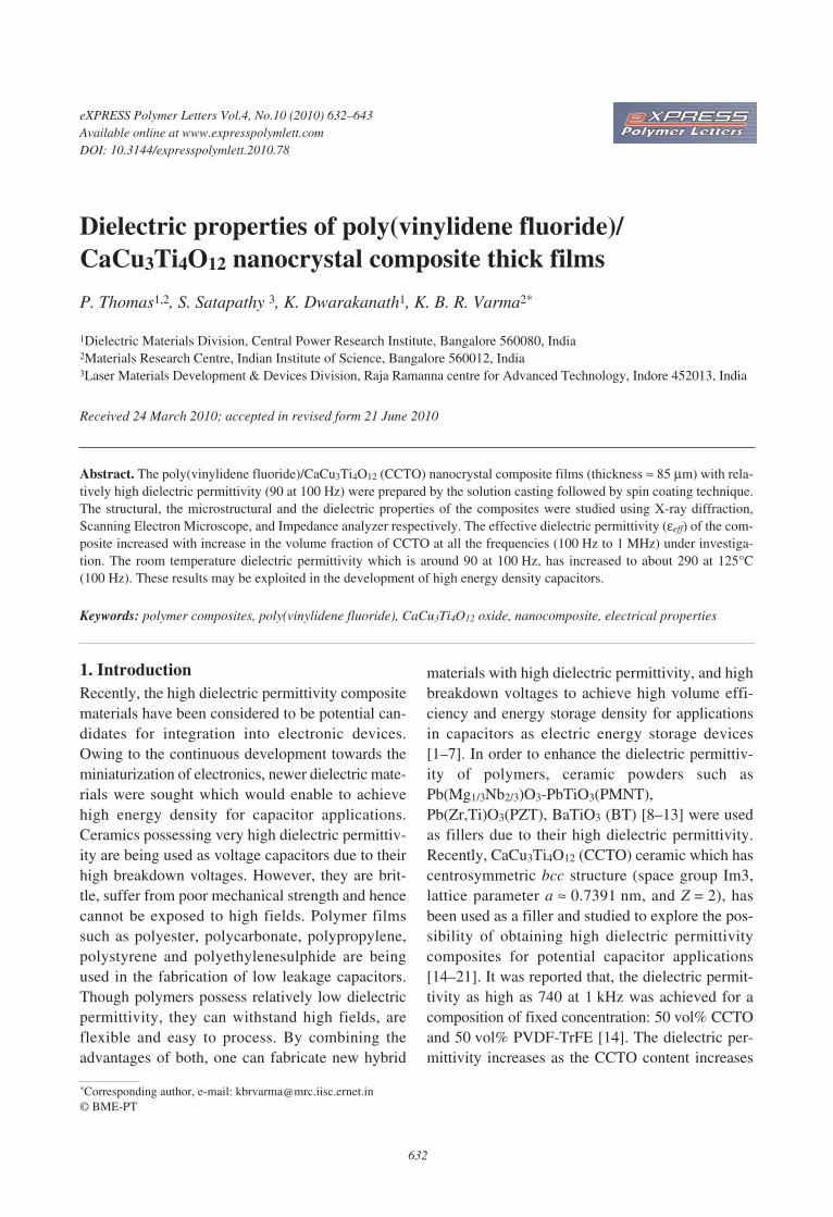
3. Results and discussion3.1. X-ray diffraction studiesThe X-ray diffraction patterns of PVDF, CCTO andseries of PVDF/CCTO composites with differentvolume percents are shown in Figure 1. The dif-fraction peaks at 20.7° (200) and 20.8° (110) indi-
cate that the PVDF exists in the β-phase [35]. Fig-ure 1b shows the X-ray diffraction pattern obtainedfor the pure CCTO nano crystalline powder com-pared well with the ICDD data (01-075-1149) andwith the pattern reported earlier [34]. The X-raydiffraction patterns obtained for the PDVF-CCTO(Figures 1c and 1d), reflect their composite nature.However, the peak intensity for β-phase of PVDFhas decreased as compared to that of CCTO in thecomposites as the volume percent of CCTOincreased in PVDF.
3.2. Morphology study by SEM/TEM
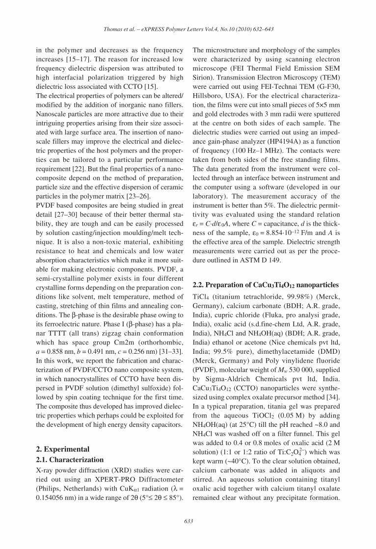
Figures 2a and 2b shows the bright field TEMimage of nano powders of CCTO and the corre-sponding SAED pattern. Figure 2a presents thebright field TEM image of the CCTO nano pow-ders obtained from the oxalate precursor and thesize of the crystallite is in the range of 20–75 nm.
634
Thomas et al. – eXPRESS Polymer Letters Vol.4, No.10 (2010) 632–643
Figure 1. The XRD diffraction patters for: (a) PVDF,(b) CCTO nanocrystalline powder and PVDF-CCTO nanocrysta composites of various con-centrations (c) 5 vol%, (d) 10 vol%, (e) 20 vol%and (f) 30 vol%
Figure 2. a) Bright field TEM images of CCTO nanocrystals with dimensions ranging from 20–75 nm, b) SAED patternwith the zone axis of [012], t2/t1 = 1.229
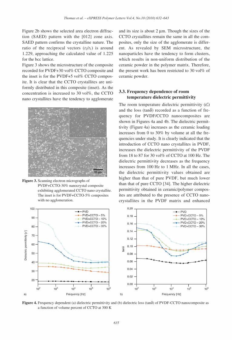
Figure 2b shows the selected area electron diffrac-tion (SAED) pattern with the [012] zone axis.SAED pattern confirms the crystalline nature. Theratio of the reciprocal vectors (t2/t1) is around1.229, approaching the calculated value of 1.225for the bcc lattice.Figure 3 shows the microstructure of the compositerecorded for PVDF+30 vol% CCTO composite andthe inset is for the PVDF+5 vol% CCTO compos-ite. It is clear that the CCTO crystallites are uni-formly distributed in this composite (inset). As theconcentration is increased to 30 vol%, the CCTOnano crystallites have the tendency to agglomerate
and its size is about 2 μm. Though the sizes of theCCTO crystallites remain the same in all the com-posites, only the size of the agglomerate is differ-ent. As revealed by SEM microstructure, thenanoparticles have the tendency to form clusters,which results in non-uniform distribution of theceramic powder in the polymer matrix. Therefore,the present work has been restricted to 30 vol% ofceramic powder.
3.3. Frequency dependence of roomtemperature dielectric permittivity
The room temperature dielectric permittivity (εr′)and the loss (tanδ) recorded as a function of fre-quency for PVDF/CCTO nanocomposites areshown in Figures 4a and 4b. The dielectric permit-tivity (Figure 4a) increases as the ceramic loadingincreases from 0 to 30% by volume at all the fre-quencies under study. It is clearly indicated that theintroduction of CCTO nano crystallites in PVDF,increases the dielectric permittivity of the PVDFfrom 18 to 87 for 30 vol% of CCTO at 100 Hz. Thedielectric permittivity decreases as the frequencyincreases from 100 Hz to 1 MHz. In all the cases,the dielectric permittivity values obtained arehigher than that of pure PVDF, but much lowerthan that of pure CCTO [34]. The higher dielectricpermittivity obtained in ceramic/polymer compos-ites are attributed to the presence of CCTO nano-crystallites in the PVDF matrix and enhanced
635
Thomas et al. – eXPRESS Polymer Letters Vol.4, No.10 (2010) 632–643
Figure 4. Frequency dependent (a) dielectric permittivity and (b) dielectric loss (tanδ) of PVDF-CCTO nanocomposite asa function of volume percent of CCTO at 300 K
Figure 3. Scanning electron micrographs ofPVDF+CCTO-30% nanocrystal compositeexhibiting agglomerated CCTO nano crystallite.The inset is for PVDF+CCTO-5% compositeswith no agglomeration.
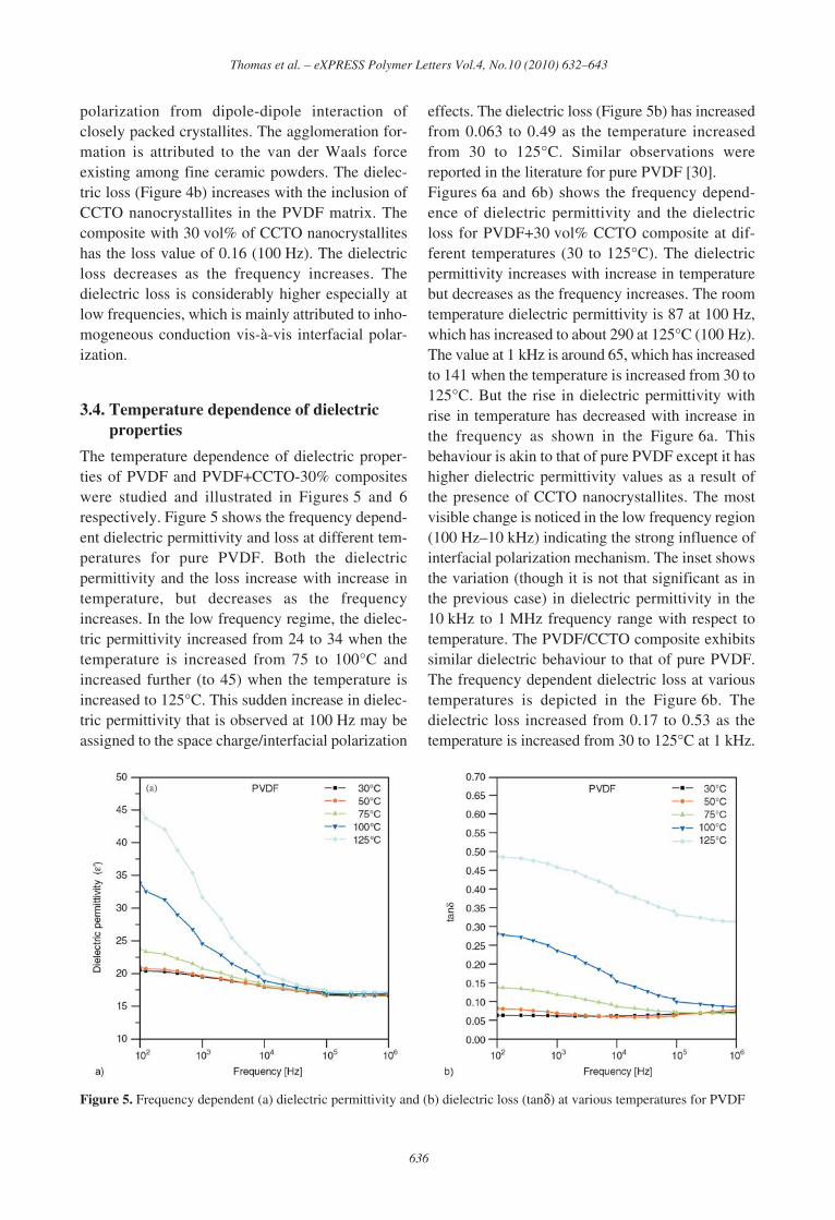
polarization from dipole-dipole interaction ofclosely packed crystallites. The agglomeration for-mation is attributed to the van der Waals forceexisting among fine ceramic powders. The dielec-tric loss (Figure 4b) increases with the inclusion ofCCTO nanocrystallites in the PVDF matrix. Thecomposite with 30 vol% of CCTO nanocrystalliteshas the loss value of 0.16 (100 Hz). The dielectricloss decreases as the frequency increases. Thedielectric loss is considerably higher especially atlow frequencies, which is mainly attributed to inho-mogeneous conduction vis-à-vis interfacial polar-ization.
3.4. Temperature dependence of dielectricproperties
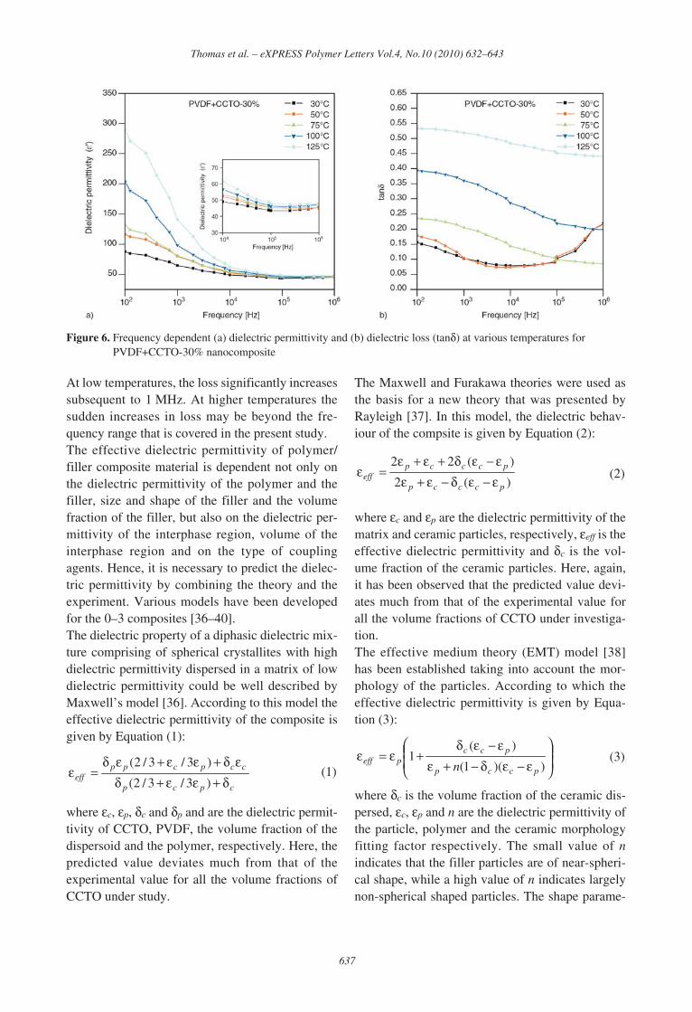
The temperature dependence of dielectric proper-ties of PVDF and PVDF+CCTO-30% compositeswere studied and illustrated in Figures 5 and 6respectively. Figure 5 shows the frequency depend-ent dielectric permittivity and loss at different tem-peratures for pure PVDF. Both the dielectricpermittivity and the loss increase with increase intemperature, but decreases as the frequencyincreases. In the low frequency regime, the dielec-tric permittivity increased from 24 to 34 when thetemperature is increased from 75 to 100°C andincreased further (to 45) when the temperature isincreased to 125°C. This sudden increase in dielec-tric permittivity that is observed at 100 Hz may beassigned to the space charge/interfacial polarization
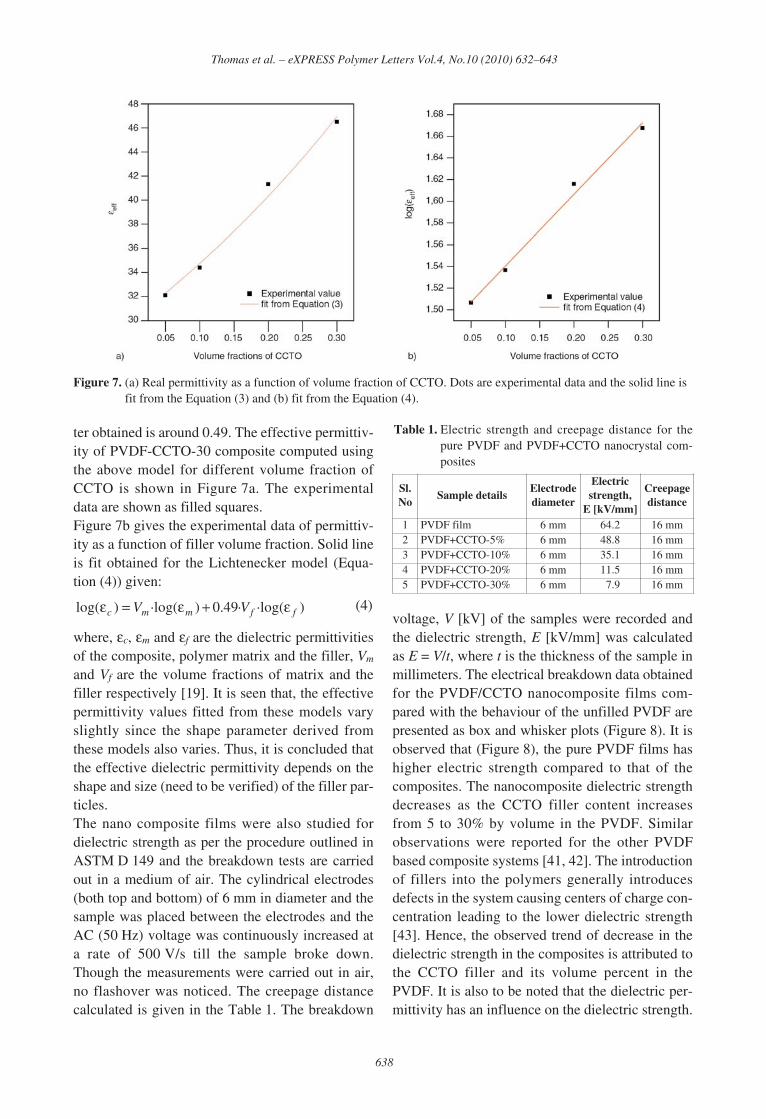
effects. The dielectric loss (Figure 5b) has increasedfrom 0.063 to 0.49 as the temperature increasedfrom 30 to 125°C. Similar observations werereported in the literature for pure PVDF [30].Figures 6a and 6b) shows the frequency depend-ence of dielectric permittivity and the dielectricloss for PVDF+30 vol% CCTO composite at dif-ferent temperatures (30 to 125°C). The dielectricpermittivity increases with increase in temperaturebut decreases as the frequency increases. The roomtemperature dielectric permittivity is 87 at 100 Hz,which has increased to about 290 at 125°C (100 Hz).The value at 1 kHz is around 65, which has increasedto 141 when the temperature is increased from 30 to125°C. But the rise in dielectric permittivity withrise in temperature has decreased with increase inthe frequency as shown in the Figure 6a. Thisbehaviour is akin to that of pure PVDF except it hashigher dielectric permittivity values as a result ofthe presence of CCTO nanocrystallites. The mostvisible change is noticed in the low frequency region(100 Hz–10 kHz) indicating the strong influence ofinterfacial polarization mechanism. The inset showsthe variation (though it is not that significant as inthe previous case) in dielectric permittivity in the10 kHz to 1 MHz frequency range with respect totemperature. The PVDF/CCTO composite exhibitssimilar dielectric behaviour to that of pure PVDF.The frequency dependent dielectric loss at varioustemperatures is depicted in the Figure 6b. Thedielectric loss increased from 0.17 to 0.53 as thetemperature is increased from 30 to 125°C at 1 kHz.
636
Thomas et al. – eXPRESS Polymer Letters Vol.4, No.10 (2010) 632–643
Figure 5. Frequency dependent (a) dielectric permittivity and (b) dielectric loss (tanδ) at various temperatures for PVDF
At low temperatures, the loss significantly increasessubsequent to 1 MHz. At higher temperatures thesudden increases in loss may be beyond the fre-quency range that is covered in the present study.The effective dielectric permittivity of polymer/filler composite material is dependent not only onthe dielectric permittivity of the polymer and thefiller, size and shape of the filler and the volumefraction of the filler, but also on the dielectric per-mittivity of the interphase region, volume of theinterphase region and on the type of couplingagents. Hence, it is necessary to predict the dielec-tric permittivity by combining the theory and theexperiment. Various models have been developedfor the 0–3 composites [36–40].The dielectric property of a diphasic dielectric mix-ture comprising of spherical crystallites with highdielectric permittivity dispersed in a matrix of lowdielectric permittivity could be well described byMaxwell’s model [36]. According to this model theeffective dielectric permittivity of the composite isgiven by Equation (1):
(1)
where εc, εp, δc and δp and are the dielectric permit-tivity of CCTO, PVDF, the volume fraction of thedispersoid and the polymer, respectively. Here, thepredicted value deviates much from that of theexperimental value for all the volume fractions ofCCTO under study.
The Maxwell and Furakawa theories were used asthe basis for a new theory that was presented byRayleigh [37]. In this model, the dielectric behav-iour of the compsite is given by Equation (2):
(2)
where εc and εp are the dielectric permittivity of thematrix and ceramic particles, respectively, εeff is theeffective dielectric permittivity and δc is the vol-ume fraction of the ceramic particles. Here, again,it has been observed that the predicted value devi-ates much from that of the experimental value forall the volume fractions of CCTO under investiga-tion.The effective medium theory (EMT) model [38]has been established taking into account the mor-phology of the particles. According to which theeffective dielectric permittivity is given by Equa-tion (3):
(3)
where δc is the volume fraction of the ceramic dis-persed, εc, εp and n are the dielectric permittivity ofthe particle, polymer and the ceramic morphologyfitting factor respectively. The small value of nindicates that the filler particles are of near-spheri-cal shape, while a high value of n indicates largelynon-spherical shaped particles. The shape parame-
⎟⎟⎠
⎞⎜⎜⎝
⎛
ε−εδ−+εε−εδ
+ε=ε))(1(
)(1
pccp
pccpeff n
)(2
)(22
pcccp
pcccpeff ε−εδ−ε+ε
ε−εδ+ε+ε=ε
cpcp
ccpcppeff δ+εε+δ
εδ+εε+εδ=ε
)3/3/2(
)3/3/2(
637
Thomas et al. – eXPRESS Polymer Letters Vol.4, No.10 (2010) 632–643
Figure 6. Frequency dependent (a) dielectric permittivity and (b) dielectric loss (tanδ) at various temperatures forPVDF+CCTO-30% nanocomposite
ter obtained is around 0.49. The effective permittiv-ity of PVDF-CCTO-30 composite computed usingthe above model for different volume fraction ofCCTO is shown in Figure 7a. The experimentaldata are shown as filled squares.Figure 7b gives the experimental data of permittiv-ity as a function of filler volume fraction. Solid lineis fit obtained for the Lichtenecker model (Equa-tion (4)) given:
(4)
where, εc, εm and εf are the dielectric permittivitiesof the composite, polymer matrix and the filler, Vm
and Vf are the volume fractions of matrix and thefiller respectively [19]. It is seen that, the effectivepermittivity values fitted from these models varyslightly since the shape parameter derived fromthese models also varies. Thus, it is concluded thatthe effective dielectric permittivity depends on theshape and size (need to be verified) of the filler par-ticles.The nano composite films were also studied fordielectric strength as per the procedure outlined inASTM D 149 and the breakdown tests are carriedout in a medium of air. The cylindrical electrodes(both top and bottom) of 6 mm in diameter and thesample was placed between the electrodes and theAC (50 Hz) voltage was continuously increased ata rate of 500 V/s till the sample broke down.Though the measurements were carried out in air,no flashover was noticed. The creepage distancecalculated is given in the Table 1. The breakdown
voltage, V [kV] of the samples were recorded andthe dielectric strength, E [kV/mm] was calculatedas E = V/t, where t is the thickness of the sample inmillimeters. The electrical breakdown data obtainedfor the PVDF/CCTO nanocomposite films com-pared with the behaviour of the unfilled PVDF arepresented as box and whisker plots (Figure 8). It isobserved that (Figure 8), the pure PVDF films hashigher electric strength compared to that of thecomposites. The nanocomposite dielectric strengthdecreases as the CCTO filler content increasesfrom 5 to 30% by volume in the PVDF. Similarobservations were reported for the other PVDFbased composite systems [41, 42]. The introductionof fillers into the polymers generally introducesdefects in the system causing centers of charge con-centration leading to the lower dielectric strength[43]. Hence, the observed trend of decrease in thedielectric strength in the composites is attributed tothe CCTO filler and its volume percent in thePVDF. It is also to be noted that the dielectric per-mittivity has an influence on the dielectric strength.
)·log(·49.0)·log()log( ffmmc VV ε+ε=ε
638
Thomas et al. – eXPRESS Polymer Letters Vol.4, No.10 (2010) 632–643
Figure 7. (a) Real permittivity as a function of volume fraction of CCTO. Dots are experimental data and the solid line isfit from the Equation (3) and (b) fit from the Equation (4).
Table 1. Electric strength and creepage distance for thepure PVDF and PVDF+CCTO nanocrystal com-posites
Sl.No
Sample detailsElectrodediameter
Electricstrength,
E [kV/mm]
Creepagedistance
1 PVDF film 6 mm 64.2 16 mm2 PVDF+CCTO-5% 6 mm 48.8 16 mm3 PVDF+CCTO-10% 6 mm 35.1 16 mm4 PVDF+CCTO-20% 6 mm 11.5 16 mm5 PVDF+CCTO-30% 6 mm 07.9 16 mm
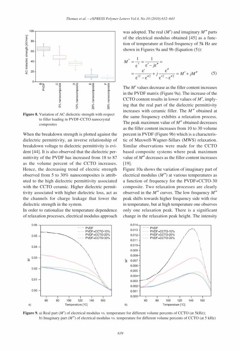
When the breakdown strength is plotted against thedielectric permittivity, an inverse relationship ofbreakdown voltage to dielectric permittivity is evi-dent [44]. It is also observed that the dielectric per-mittivity of the PVDF has increased from 18 to 87as the volume percent of the CCTO increases.Hence, the decreasing trend of electric strengthobserved from 5 to 30% nanocomposites is attrib-uted to the high dielectric permittivity associatedwith the CCTO ceramic. Higher dielectric permit-tivity associated with higher dielectric loss, act asthe channels for charge leakage that lower thedielectric strength in the system.In order to rationalize the temperature dependenceof relaxation processes, electrical modulus approach
was adopted. The real (M′) and imaginary M″ partsof the electrical modulus obtained [45] as a func-tion of temperature at fixed frequency of 5k Hz areshown in Figures 9a and 9b (Equation (5)):
(5)
The M′ values decrease as the filler content increasesin the PVDF matrix (Figure 9a). The increase of theCCTO content results in lower values of M′, imply-ing that the real part of the dielectric permittivityincreases with ceramic filler. The M ″ obtained atthe same frequency exhibits a relaxation process.The peak maximum value of M″ obtained decreasesas the filler content increases from 10 to 30 volumepercent in PVDF (Figure 9b) which is a characteris-tic of Maxwell-Wagner-Sillars (MWS) relaxation.Similar observations were made for the CCTObased composite systems where peak maximumvalue of M″ decreases as the filler content increases[19].Figure 10a shows the variation of imaginary part ofelectrical modulus (M″) at various temperatures asa function of frequency for the PVDF+CCTO-30composite. Two relaxation processes are clearlyobserved in the M″ curves. The low frequency M″peak shifts towards higher frequency side with risein temperature, but at high temperature one observesonly one relaxation peak. There is a significantchange in the relaxation peak height. The intensity
MjMj
jM
′′+′=ε ′′−ε′
ε ′′+
ε ′′−ε′ε=
=ε ′′−ε′
=ε
=
2222
**
'
11
639
Thomas et al. – eXPRESS Polymer Letters Vol.4, No.10 (2010) 632–643
Figure 9. a) Real part (M′) of electrical modulus vs. temperature for different volume percents of CCTO (at 5kHz);b) Imaginary part (M″) of electrical modulus vs. temperature for different volume percents of CCTO (at 5 kHz)
Figure 8. Variation of AC dielectric strength with respectto filler loading in PVDF-CCTO nanocrystalcomposites
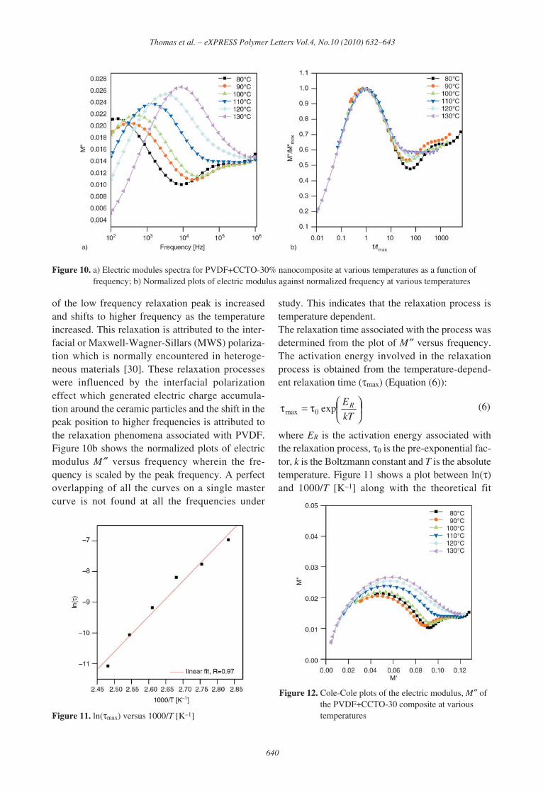
of the low frequency relaxation peak is increasedand shifts to higher frequency as the temperatureincreased. This relaxation is attributed to the inter-facial or Maxwell-Wagner-Sillars (MWS) polariza-tion which is normally encountered in heteroge-neous materials [30]. These relaxation processeswere influenced by the interfacial polarizationeffect which generated electric charge accumula-tion around the ceramic particles and the shift in thepeak position to higher frequencies is attributed tothe relaxation phenomena associated with PVDF.Figure 10b shows the normalized plots of electricmodulus M″ versus frequency wherein the fre-quency is scaled by the peak frequency. A perfectoverlapping of all the curves on a single mastercurve is not found at all the frequencies under
study. This indicates that the relaxation process istemperature dependent.The relaxation time associated with the process wasdetermined from the plot of M″ versus frequency.The activation energy involved in the relaxationprocess is obtained from the temperature-depend-ent relaxation time (τmax) (Equation (6)):
(6)
where ER is the activation energy associated withthe relaxation process, τ0 is the pre-exponential fac-tor, k is the Boltzmann constant and T is the absolutetemperature. Figure 11 shows a plot between ln(τ)and 1000/T [K–1] along with the theoretical fit
⎟⎠⎞⎜
⎝⎛τ=τ
kT
ERexp0max
640
Thomas et al. – eXPRESS Polymer Letters Vol.4, No.10 (2010) 632–643
Figure 10. a) Electric modules spectra for PVDF+CCTO-30% nanocomposite at various temperatures as a function offrequency; b) Normalized plots of electric modulus against normalized frequency at various temperatures
Figure 11. ln(τmax) versus 1000/T [K–1]
Figure 12. Cole-Cole plots of the electric modulus, M″ ofthe PVDF+CCTO-30 composite at varioustemperatures
(solid line) to the above equation (Equation (6)).The value that is obtained for ER is 0.97±0.03 eV isattributed to the relaxation arising from the interfa-cial polarization.In Figure 12, we show the Cole-Cole plot for thePVDF+CCTO-30 composite at various tempera-tures. In these plots, two distinct semicircles areclearly noticed. The high frequency end semicircleis attributed to the composite nature while the lowfrequency semicircle is attributed to the interfacialphenomenon occurring between the CCTO parti-cles and the polymer.
4. Conclusions
High dielectric permittivity poly(vinylidene fluo-ride (PVDF)/CaCu3Ti4O12 (CCTO) nanocrystalcomposite films were fabricated. The dielectric per-mittivity of PVDF increases with increase in CCTOcontent. The PVDF+CCTO-30% nanocompositeshowed higher dielectric permittivity than that ofpure PVDF and the other composites under study.The relaxation processes associated with thesecomposites were attributed to the interfacial polar-ization or MWS effect. Though there is an improve-ment in the dielectric permittivity, the decrease indielectric breakdown may limit its use for highvoltage applications.
AcknowledgementsThe management of Central Power Research Institute isacknowledged for the financial support. (Project No.5.4.49). Thanks are due to Mr. Asai Thambi, Engineeringofficer, CPRI for breakdown voltage test.
References[1] Newnham R. E.: Composite electroceramics. Annual
Review of Materials Science, 16, 47–68 (1986).DOI: 10.1146/annurev.ms.16.080186.000403
[2] Das-Gupta D. K.: Piezoelectricity and pyroelectricity.Key Engineering Materials, 92–93, 1–14 (1994).DOI: 10.4028/www.scientific.net/KEM.92-93.1
[3] Dias C. J., Das-Gupta D. K.: Inorganic ceramic/poly-mer ferroelectric composite electrets. IEEE Transac-tions on Dielectric and Electrical Insulation, 3, 706–734 (1996).DOI: 10.1109/94.544188
[4] Kuo D-H., Chang C-C., Su T-Y., Wang W-K., Lin B-Y.: Dielectric behaviours of multi-doped BaTiO3/epoxy composites. Journal of the European CeramicSociety, 21, 1171–1176 (2001).DOI: 10.1016/S0955-2219(00)00327-7
[5] Das-Gupta D. K., Doughty K.: Polymer-ceramic com-posite materials with high dielectric constants. ThinSolid Films, 158, 93–105 (1988).DOI: 10.1016/0040-6090(88)90306-9
[6] Malecki J., Hilczer B.: Dielectric behaviour of poly-mers and composites. Key Engineering Materials,92–93, 181–216 (1994).DOI: 10.4028/www.scientific.net/KEM.92-93.181
[7] Chahal P., Tummala R. R., Allen M. G., SwaminathanM.: A novel integrated decoupling capacitor forMCM-L technology. IEEE Transaction on Compo-nents: Packaging, and Manufacturing Technology, 21,184–193 (1998).DOI: 10.1109/96.673707
[8] Bai Y., Cheng Z-Y., Bharti V., Xu H., Zhang Q. M.:High-dielectric-constant ceramic-powder polymercomposites. Journal of Applied Physics Letters, 76,3804–3806 (2000).DOI: 10.1063/1.126787
[9] Adikary S. U., Chan H. L. W., Choy C. L., SundaravelB., Wilson I. H.: Characterisation of proton irradiatedBa0.65Sr0.35TiO3/P(VDF-TrFE) ceramic-polymer com-posites. Composites Science and Technology, 62,2161–2167 (2002).DOI: 10.1016/S0266-3538(02)00149-5
[10] Dang Z-M., Yu Y-F., Xu H-P., Bai J.: Study onmicrostructure and dielectric property of the BaTiO3/epoxy resin composites. Composites Science and Tech-nology, 68, 171–177 (2008).DOI: 10.1016/j.compscitech.2007.05.021
[11] Sekar R., Tripathi A. K., Pillai P. K. C.: X-ray diffrac-tion and dielectric studies of a BaTiO3: PVDF com-posite. Materials Science and Engineering: B, 5, 33–36 (1989).DOI: 10.1016/0921-5107(89)90302-4
[12] Muralidhar C., Pillai P. K. C.: Dielectric behaviour ofbarium titanate-polyvinylidene fluoride composites.Journal of Materials Science, 23, 1071–1076 (1988).DOI: 10.1007/BF01154015
[13] Zhang Z-M., Shen Y., Nan C-W.: Dielectric behaviorof three-phase percolative Ni-BaTiO3/polyvinylidenefluoride composites. Journal of Applied Physics Let-ters, 81, 4814–4816 (2002).DOI: 10.1063/1.1529085
[14] Arbatti M., Shan X., Cheng Z-Y.: Ceramic-polymercomposites with high dielectric permittivity. AdvancedMaterials, 19, 1369–1372 (2007).DOI: 10.1002/adma.200601996
641
Thomas et al. – eXPRESS Polymer Letters Vol.4, No.10 (2010) 632–643
[15] Shri Prakash B., Varma K. B. R.: Dielectric behaviorof CCTO/epoxy and Al-CCTO/epoxy composites.Composites Science and Technology, 67, 2363–2368(2007).DOI: 10.1016/j.compscitech.2007.01.010
[16] Tuncer E., Sauers I., James D. R., Ellis A. R., Paran-thaman M. P., Tolga A. T., Sathyamurthy S., KarrenL. M., Li J., Goyal A.: Electrical properties of epoxyresin based nanocomposites. Nanotechnology, 18,25703–25706 (2007).DOI: 10.1088/0957-4484/18/2/025703
[17] Amaral F., Rubinger C. P. L, Henry F., Costa L. C.,Valente M. A., Barros-Timmons A.: Dielectric prop-erties of polystyrene-CCTO composite. Journal ofNon Crystalline Solids, 354, 5321–5322 (2008).DOI: 10.1016/j.jnoncrysol.2008.05.056
[18] Thomas P., Dwarakanath K., Varma K. B. R.: Insitu synthesis and characterization of polyaniline-CaCu3Ti4O12 nanocrystal composites. Synthetic Met-als, 159, 2128–2134 (2009) DOI: 10.1016/j.synthmet.2009.08.001
[19] Ramajo L. A., Ramírez M. A., Bueno P. R., ReboredoM. M., Castro M. S.: Dielectric behaviour ofCaCu3Ti4O12-epoxy composites. Materials Research,11, 85–88 (2008).DOI: 10.1590/S1516-14392008000100016
[20] Patsidis A., Psarras G. C.: Dielectric behaviour andfunctionality of polymer matrix – ceramic BaTiO3
composites. Express Polymer Letters, 2, 718–726(2008).DOI: 10.3144/expresspolymlett.2008.85
[21] Thomas P., Varughese K. T. V., Dwarakanatha K.,Varma K. B. R.: Dielectric properties of poly(vinyli-dene fluoride)/CaCu3Ti4O12 composites. CompositesScience and Technology, 70, 539–545 (2010).DOI: 10.1016/j.compscitech.2009.12.014
[22] Nalwa H. S.: Handbook of low and high dielectric per-mittivity materials and their applications, phenomena,properties and applications. Academic Press, SanDiego (1999).
[23] Chiang C. K., Popielarz R.: Polymer composites withhigh dielectric permittivity. Ferroelectrics, 275, 1–9(2002).DOI: 10.1080/00150190214285
[24] Hsiang H-I., Yin K-Y., Yen F-S., Hwang C-Y.:Effects of particle size of BaTiO3 powder on thedielectric properties of BaTiO3/polyvinylidene fluo-ride composites. Journal of Materials Science, 36,3809–3815 (2001)DOI: 10.1023/A:1017946405447
[25] Ishida H., Campbell S., Blackwell J.: General approachto polymer nanocomposite preparation. Chemistry ofMaterials, 12, 1260–1267 (2000).DOI: 10.1021/cm990479y
[26] Kontos G. A., Soulintzis A. L., Karahaliou P. K., Psar-ras G. C., Georga S. N., Krontiras C. A., Pisanias M.N.: Electrical relaxation dynamics in TiO2-polymermatrix composites. Express Polymer Letters, 1, 781–789 (2007).DOI: 10.3144/expresspolymlett.2007.108
[27] Djidjelli H., Benachour D., Boukerrou A., Zefouni O.,Martinez-Véga J., Farenc J., Kaci M.: Thermal, dielec-tric and mechanical study of poly (vinyl chloride)/olive pomace composites. Express Polymer Letters, 1,846–852 (2007).DOI: 10.3144/expresspolymlett.2007.117
[28] Muralidhar C., Pillai P. K. C.: Dielectric behaviour ofbarium titanate (BaTiO3)/polyvinylidene fluoride(PVDF) composite. Journal of Materials Science Let-ters, 6, 346–348 (1987).DOI: 10.1007/BF01729348
[29] Dang Z-M., Wang H-Y., Zhang Y-H., Qi J-Q.: Mor-phology and dielectric property of homogenousBaTiO3/PVDF nanocomposites prepared via the natu-ral adsorption action of nanosized BaTiO3. Macromol-ecular Rapid Communications, 26, 1185–1189 (2005).DOI: 10.1002/marc.200500137
[30] Chanmal C. V., Jog J. P.: Dielectric relaxations inPVDF/BaTiO3 nanocomposites. Express Polymer Let-ters, 2, 294–301 (2008).DOI: 10.3144/expresspolymlett.2008.35
[31] Lando J. B., Olf H. G., Peterlin A.: Nuclear magneticresonance and X-ray determination of the structure ofpoly(vinylidene fluoride). Journal of Polymer SciencePart A-1: Polymer Chemistry, 4, 941–951 (1966).DOI: 10.1002/pol.1966.150040420
[32] Hasegawa R., Takahashi Y., Chatani Y., Tadokoro H.:Crystal structures of three crystalline forms ofpoly(vinylidene fluoride). Polymer Journal, 3, 600–610 (1972).DOI: 10.1295/polymj.3.600
[33] Weinhold S., Litt M. H., Lando J. B.: The crystalstructure of the γ phase of poly(vinylidene fluoride).Macromolecules, 13, 1178–1183 (1980).DOI: 10.1021/ma60077a029
[34] Thomas P., Dwarakanath K., Varma K. B. R., Kutty T.R. N.: Synthesis of nanoparticles of the giant dielectricmaterial, CaCu3Ti4O12 from a precursor route. Journalof Thermal Analysis and Calorimetry, 95, 267–272(2009).DOI: 10.1007/s10973-007-8981-z
[35] Esterly M. D., Love B. J.: Phase transformation to β-poly(vinylidene fluoride) by milling. Journal of Poly-mer Science Part B: Polymer Physics, 42, 91–97(2004).DOI: 10.1002/polb.10613
[36] Maxwell J. C.: A treatise on electricity and magnet-ism. Dover Publications, New York (1954).
642
Thomas et al. – eXPRESS Polymer Letters Vol.4, No.10 (2010) 632–643
[37] Bhimsankaran T., Suryanarayana S. V., Prasad G.:Piezoelectric polymer composite materials. CurrentScience, 74, 967–976 (1998).
[38] Rao Y., Qu J., Marinis T., Wong C. P.: A precisenumerical prediction of effective dielectric permittiv-ity for polymer-ceramic composite based on effective-medium theory. IEEE Transactions on Componentsand Packaging Technologies, 23, 680–683 (2000).DOI: 10.1109/6144.888853
[39] Yamada T., Ueda T., Kitayama T.: Piezoelectricity ofa high-content lead zirconate titanate/polymer com-posite. Journal of Applied Physics, 53, 4328–4332(1982).DOI: 10.1063/1.331211
[40] Lunkenheimer P., Fichtl P., Ebbinghaus S. G., LoidlA.: Nonintrinsic origin of the colossal dielectric con-stants in CaCu3Ti4O12. Physical Review B, 70,172102–172105 (2004).DOI: 10.1103/PhysRevB.70.172102
[41] Dou X., Liu X., Zhang Y., Feng H., Chen J-F., Du S.:Improved dielectric strength of barium titanate-polyvinylidene fluoride nanocomposite. AppliedPhysics Letters, 95, 132904–132906 (2009).DOI: 10.1063/1.3242004
[42] Aulagner E., Guillet J., Seytre S., Hantouche C., LeGonidec P., Terzulli G.: (PVDF/BaTiO3) and (PP/BaTiO3) films for energy storage apacitors. in ‘IEEE5th International Conference on Conduction and Break-down in Solid Dielectrics, Leicester, England’ 423–427 (1995).DOI: 10.1109/ICSD.1995.523021
[43] Singha S., Thomas M. J.: Dielectric properties ofepoxy nanocomposites. IEEE Transactions onDielectrics and Electrical Insulation, 15, 12–23(2008).DOI: 10.1109/T-DEI.2008.4446732
[44] McPherson J., Kim J-Y., Shanware A., Mogul H.:Thermochemical description of dielectric breakdownin high dielectric constant materials. Applied PhysicsLetters, 82, 2121–2123 (2003).DOI: 10.1063/1.1565180
[45] Ramajo L., Reboredo M., Castro M.: Dielectricresponse and relaxation phenomena in composites ofepoxy with BaTiO3 particles. Composites Part A:Applied Science and Manufacturing, 36, 1267–1274(2005).DOI: 10.1016/j.compositesa.2005.01.026
643
Thomas et al. – eXPRESS Polymer Letters Vol.4, No.10 (2010) 632–643
![[hal-00447403, v1] From Vinylidene Fluoride (VDF) to the ... · 6 HCF C -142b is the commercially prefe rred monomer precursor, obtained by hydrofluorination of acetylene 19, vinylidene](https://img.pdfslide.net/doc/110x75/5edc88e9ad6a402d66673c17/hal-00447403-v1-from-vinylidene-fluoride-vdf-to-the-6-hcf-c-142b-is-the.jpg)


![Multilayered Assembly of Poly(Vinylidene Fluoride) and ...€¦ · quadruple-shape memory effect.[12] Based on this principle, the intermediate shapes of a MSMP can be finely tuned](https://img.pdfslide.net/doc/110x75/600ebd09034e3b7c5e1d27ff/multilayered-assembly-of-polyvinylidene-fluoride-and-quadruple-shape-memory.jpg)