Embed Size (px)
Citation preview
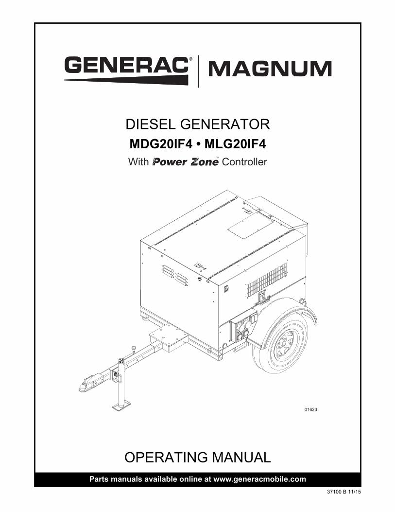
OPERATING MANUALParts manuals available online at www.generacmobile.com
01623
DIESEL GENERATOR
With ControllerTM
MDG20IF4 • MLG20IF4
37100 B 11/15
WARNINGCALIFORNIA PROPOSITION 65 WARNING: Diesel engine exhaust and some of its
constituents are known to the state of California to cause cancer, birth defects, and other reproductive harm.
WARNINGCALIFORNIA PROPOSITION 65 WARNING: This product contains or emits chemicals known to the state of California to cause cancer, birth defects, and other reproductive
harm.
WARNINGENVIRONMENTAL HAZARD: Always recycle batteries at an official recycling center in
accordance with all local laws and regulations. Failure to do so could result in environmental damage, death or serious injury.
ii

Introduction
This manual provides information and procedures to safely operate and maintain the Generac Mobile Products unit. For your own safety and protection from physical injury, carefully read, understand, and observe the safety instructions described in this manual. Keep a copy of this manual with the unit at all times. Additional copies are available from Generac Mobile Products, or can be found at www.generacmobile.com.The information contained in this manual was based on machines in production at the time of publication. Generac Mobile Products reserves the right to change any portion of this information without notice.
Read all of the manuals included with the unit. Each manual details specific information regarding items such as setup, use and service requirements. An engine operator’s manual provides detailed operation and maintenance procedures for the engine. Additional copies of the engine operator’s manual are available from the engine manufacturer.
DO NOT MODIFY or use this equipment for any application other than for which it was designed.
Only a trained and licensed electrician should perform wiring and connections to unit. Wiring must be in compliance with National Electrical Code (NEC), state and local regulations, as well as Occupational Safety and Health Administration (OSHA) guidelines.
GENERAC MOBILE PRODUCTS LLC215 Power Drive • Berlin, WI 54923
U.S.A.Phone: 920-361-4442FAX: 920-361-4416
Toll Free: 1-800-926-9768www.generacmobile.com
For technical or parts QUESTIONS, please contact the Generac Mobile Products Technical Service team at 1-800-926-9768. Please have your serial number available.
To ORDER SERVICE PARTS, please contact the dealer from which you purchased the unit, or call Generac Mobile Products to locate a dealer in your area.
Engine Make:__________________________________________Engine Serial Number:___________________________________Engine Model Number: __________________________________Generator Make: _______________________________________Generator Model Number:________________________________Generator Serial Number: ________________________________Unit Model Number:_____________________________________Unit Serial Number: _____________________________________
iii

This Page Intentionally Left Blank
iv
Table of Contents
Introduction............................................................................................................................ iiiSection 1 - Safety
Safety Notes ....................................................................................................................................... 1Operating Safety................................................................................................................................. 1Engine Safety ..................................................................................................................................... 2Service Safety .................................................................................................................................... 2Towing Safety..................................................................................................................................... 3Reporting Trailer Safety Defects ........................................................................................................ 3Safety Symbol Summary .................................................................................................................... 4
Section 2 - General InformationSpecifications ..................................................................................................................................... 5
Unit Dimensions .................................................................................................................... 6Unit Serial Number Locations............................................................................................................. 6Component Locations......................................................................................................................... 7Control Panel...................................................................................................................................... 8Power Zone™ Light Controller ........................................................................................................... 9
Controller Features and Functions ........................................................................................ 9Operator Screens ................................................................................................................ 10Maintenance Screens.......................................................................................................... 12Navigation Menu Icons ....................................................................................................... 12Possible DTC Faults........................................................................................................... 13
Section 3 - OperationPrestart Checklist ............................................................................................................................. 17Manually Starting the Unit ................................................................................................................ 17Auto (Remote) Starting of the Unit ................................................................................................... 18Voltage Regulator............................................................................................................................. 18Derating for Altitude.......................................................................................................................... 18Wet Stacking .................................................................................................................................... 18Customer Convenience Receptacles ............................................................................................... 19Transfer Switch................................................................................................................................. 19Auto Exercise Timer ......................................................................................................................... 20
Accessing the Scheduler ..................................................................................................... 21Set the Controller Clock....................................................................................................... 21Set the Schedule ................................................................................................................. 21Set the Unit to Auto Mode ................................................................................................... 22
Shutting Down the Unit..................................................................................................................... 22Emergency Stop ............................................................................................................................... 23Towing the Unit................................................................................................................................. 23Lifting the Unit................................................................................................................................... 24
Section 4 - MaintenanceDaily Walk Around Inspection........................................................................................................... 25General Maintenance ....................................................................................................................... 25Basic Maintenance Schedule ........................................................................................................... 26
Isuzu Engine Maintenance Schedule ................................................................................. 26Resetting the Maintenance Alarms................................................................................................... 26Jack Maintenance............................................................................................................................. 27
Side-Wind Models ............................................................................................................... 27Top-Wind Models ................................................................................................................ 28
Trailer Wheel Bearings ..................................................................................................................... 28
Section 5 - TroubleshootingGeneral Troubleshooting .................................................................................................................. 29
General Troubleshooting Guide ......................................................................................... 29
v
Section 6 - Wiring DiagramsAC Wiring ......................................................................................................................................... 31AC Wiring - Customer Convenience Receptacles............................................................................ 32AC Wiring - Customer Convenience Receptacle Options (1 of 2).................................................... 33AC Wiring - Customer Convenience Receptacle Options (2 of 2).................................................... 34DC Wiring ......................................................................................................................................... 35DC Wiring Options............................................................................................................................ 36Trailer Lights Wiring.......................................................................................................................... 37
Section 7 - Options & AccessoriesLower Radiator Hose Heater Option - Use and Maintenance .......................................................... 39
Service Log ............................................................................................................................ 41
vi
Section 1 - Safety
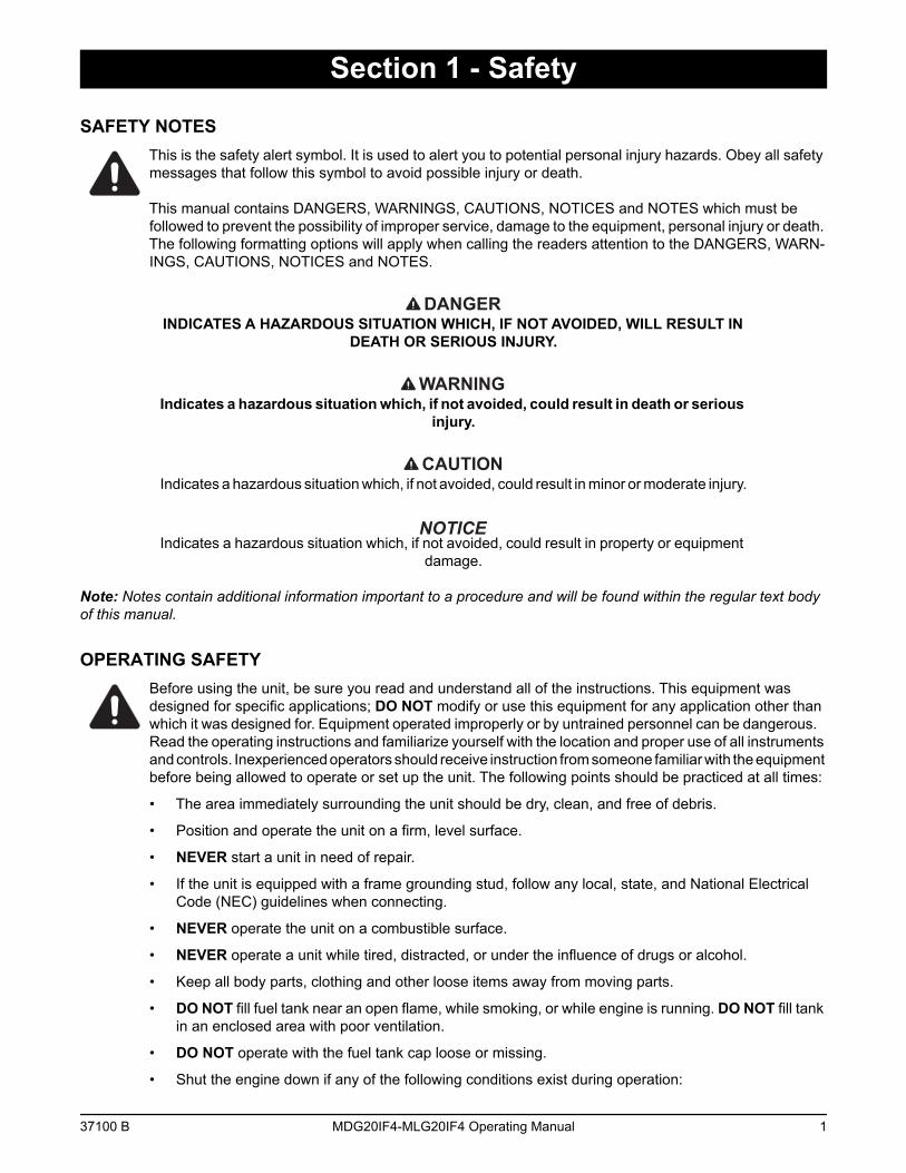
SAFETY NOTESThis is the safety alert symbol. It is used to alert you to potential personal injury hazards. Obey all safety messages that follow this symbol to avoid possible injury or death.
This manual contains DANGERS, WARNINGS, CAUTIONS, NOTICES and NOTES which must be followed to prevent the possibility of improper service, damage to the equipment, personal injury or death. The following formatting options will apply when calling the readers attention to the DANGERS, WARN-INGS, CAUTIONS, NOTICES and NOTES.
DANGERINDICATES A HAZARDOUS SITUATION WHICH, IF NOT AVOIDED, WILL RESULT IN
DEATH OR SERIOUS INJURY.
WARNINGIndicates a hazardous situation which, if not avoided, could result in death or serious
injury.
CAUTIONIndicates a hazardous situation which, if not avoided, could result in minor or moderate injury.
Indicates a hazardous situation which, if not avoided, could result in property or equipment damage.
Note: Notes contain additional information important to a procedure and will be found within the regular text body of this manual.
OPERATING SAFETYBefore using the unit, be sure you read and understand all of the instructions. This equipment was designed for specific applications; DO NOT modify or use this equipment for any application other than which it was designed for. Equipment operated improperly or by untrained personnel can be dangerous. Read the operating instructions and familiarize yourself with the location and proper use of all instruments and controls. Inexperienced operators should receive instruction from someone familiar with the equipment before being allowed to operate or set up the unit. The following points should be practiced at all times:
• The area immediately surrounding the unit should be dry, clean, and free of debris.
• Position and operate the unit on a firm, level surface.
• NEVER start a unit in need of repair.
• If the unit is equipped with a frame grounding stud, follow any local, state, and National Electrical Code (NEC) guidelines when connecting.
• NEVER operate the unit on a combustible surface.
• NEVER operate a unit while tired, distracted, or under the influence of drugs or alcohol.
• Keep all body parts, clothing and other loose items away from moving parts.
• DO NOT fill fuel tank near an open flame, while smoking, or while engine is running. DO NOT fill tank in an enclosed area with poor ventilation.
• DO NOT operate with the fuel tank cap loose or missing.
• Shut the engine down if any of the following conditions exist during operation:
37100 B MDG20IF4-MLG20IF4 Operating Manual 1
Safety
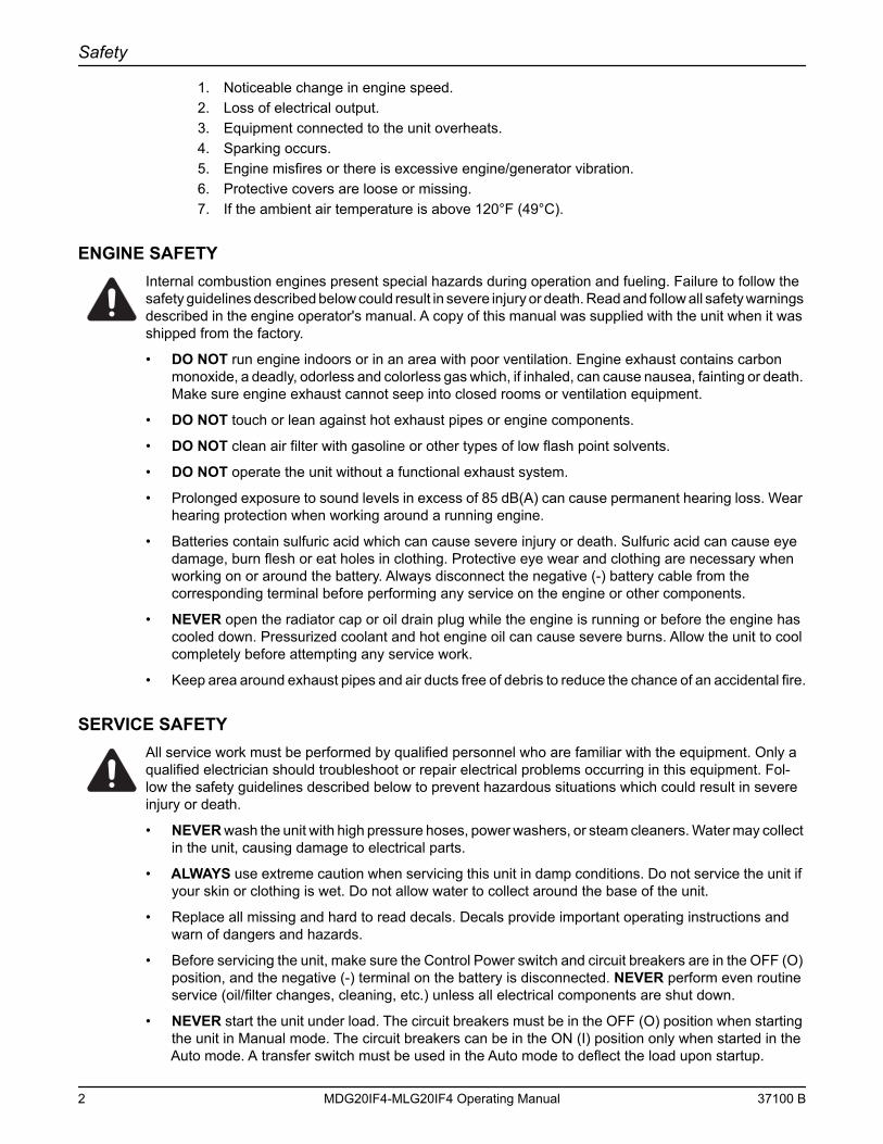
1. Noticeable change in engine speed.2. Loss of electrical output.3. Equipment connected to the unit overheats.4. Sparking occurs.5. Engine misfires or there is excessive engine/generator vibration.6. Protective covers are loose or missing.7. If the ambient air temperature is above 120°F (49°C).
ENGINE SAFETYInternal combustion engines present special hazards during operation and fueling. Failure to follow the safety guidelines described below could result in severe injury or death. Read and follow all safety warnings described in the engine operator's manual. A copy of this manual was supplied with the unit when it was shipped from the factory.
• DO NOT run engine indoors or in an area with poor ventilation. Engine exhaust contains carbon monoxide, a deadly, odorless and colorless gas which, if inhaled, can cause nausea, fainting or death. Make sure engine exhaust cannot seep into closed rooms or ventilation equipment.
• DO NOT touch or lean against hot exhaust pipes or engine components.
• DO NOT clean air filter with gasoline or other types of low flash point solvents.
• DO NOT operate the unit without a functional exhaust system.
• Prolonged exposure to sound levels in excess of 85 dB(A) can cause permanent hearing loss. Wear hearing protection when working around a running engine.
• Batteries contain sulfuric acid which can cause severe injury or death. Sulfuric acid can cause eye damage, burn flesh or eat holes in clothing. Protective eye wear and clothing are necessary when working on or around the battery. Always disconnect the negative (-) battery cable from the corresponding terminal before performing any service on the engine or other components.
• NEVER open the radiator cap or oil drain plug while the engine is running or before the engine has cooled down. Pressurized coolant and hot engine oil can cause severe burns. Allow the unit to cool completely before attempting any service work.
• Keep area around exhaust pipes and air ducts free of debris to reduce the chance of an accidental fire.
SERVICE SAFETYAll service work must be performed by qualified personnel who are familiar with the equipment. Only a qualified electrician should troubleshoot or repair electrical problems occurring in this equipment. Fol-low the safety guidelines described below to prevent hazardous situations which could result in severe injury or death.
• NEVER wash the unit with high pressure hoses, power washers, or steam cleaners. Water may collect in the unit, causing damage to electrical parts.
• ALWAYS use extreme caution when servicing this unit in damp conditions. Do not service the unit if your skin or clothing is wet. Do not allow water to collect around the base of the unit.
• Replace all missing and hard to read decals. Decals provide important operating instructions and warn of dangers and hazards.
• Before servicing the unit, make sure the Control Power switch and circuit breakers are in the OFF (O) position, and the negative (-) terminal on the battery is disconnected. NEVER perform even routine service (oil/filter changes, cleaning, etc.) unless all electrical components are shut down.
• NEVER start the unit under load. The circuit breakers must be in the OFF (O) position when starting the unit in Manual mode. The circuit breakers can be in the ON (I) position only when started in the Auto mode. A transfer switch must be used in the Auto mode to deflect the load upon startup.
2 MDG20IF4-MLG20IF4 Operating Manual 37100 B
Safety
TOWING SAFETYTowing a trailer requires care. Both the trailer and vehicle must be in good condition and securely fastened to each other to reduce the possibility of an accident. Some states require that large trailers be registered and licensed. Contact your local Department of Transportation office to check on license requirements for your particular unit.
• Check that the hitch and coupling on the towing vehicle are rated equal to, or greater than, the trailer's Gross Vehicle Weight Rating (GVWR).
• Check tires on trailer for tread wear, inflation, and condition.
• NEVER tow trailer using defective parts. Inspect the hitch and coupling for wear or damage.
• Make sure the trailer hitch and the coupling are compatible. Make sure the coupling is securely fastened to the vehicle.
• Make sure directional and brake lights on the trailer are connected and working properly.
• Check that the lug nuts holding the wheels are tight and that none are missing.
• Maximum recommended speed for highway towing is 45 mph (72 km/h). Recommended off-road towing speed is not to exceed 10 mph (16 km/h) or less, depending on terrain.
• When towing, maintain extra space between vehicles and avoid soft shoulders, curbs and sudden lane changes. If you have not pulled a trailer before, practice turning, stopping and backing up in an area away from heavy traffic.
• A film of grease on the coupler will extend coupler life and eliminate squeaking. Wipe the coupler clean and apply fresh grease each time the trailer is towed.
• Connect safety chains in a crossing pattern under the tongue.
• Before towing the trailer, check that the weight of the trailer is equal across all tires. On trailers with adjustable height hitches, adjust the angle of the trailer tongue to keep the trailer as level as possible.
REPORTING TRAILER SAFETY DEFECTSIf you believe your trailer has a defect which could cause a crash or could cause injury or death, you should immediately inform the National Highway Traffic Safety Administration (NHTSA) in addition to notifying Generac Mobile Products LLC.
If NHTSA receives similar complaints, it may open an investigation; and if it finds that a safety defect exists in a group of vehicles, it may order a recall and remedy campaign. However, NHTSA cannot become involved in an individual problem between you, your dealer, or Generac Mobile Products LLC.
To contact NHTSA, you may either call the Auto Safety Hotline toll-free at 1-888-327-4236 (TTY:1-800-424-9153), go to http://www.safercar.gov; or write to:
AdministratorNHTSA1200 New Jersey Avenue S.E.Washington, DC 20590
You can also obtain other information about motor vehicle safety from http://www.safercar.gov.
37100 B MDG20IF4-MLG20IF4 Operating Manual 3
Safety
SAFETY SYMBOL SUMMARYThis equipment has been supplied with numerous safety and operating decals. These decals provide important operating instructions and warn of dangers and hazards. Replace any missing or hard-to-read decals and use care when washing or cleaning the unit. Decal placement and part numbers can be found in the online parts manual at www.generacmobile.com. Below is a summary of the intended meanings for the symbols used on the decals.
00846
STOP
Hot surface(s) nearby.
Unit electrical ground.
Anchor/tie down point.
Stop engine.
Dangerous voltage may be present.
Asphyxiation hazard; operate in well venti-lated area.
Fan hazard; keep body parts clear of this area.
Belt/entanglementhazard; keep body partsclear of this area.
Safety alert symbol;used to alert youto potential hazards.
Read and understand the operator’s manual before operating.
Disconnect battery before servicing.
Check diesel fuel fill level.
Do not remove guard.
Burn/scald hazard; pressurized steam.
Fire/explosion hazard;keep open flamesaway from unit.
Automatic Start
4 MDG20IF4-MLG20IF4 Operating Manual 37100 B
Section 2 - General Information
SPECIFICATIONSGENERAC MODEL MDG20IF4 • MLG20IF4
EngineMake/Brand........................................................................................................................... IsuzuModel .................................................................................................................................... 4LE2TAGV-03EPA Tier ................................................................................................................................ F4Horsepower - Prime hp (kW) ............................................................................................... 36.2 (27.0)Horsepower - Standby hp (kW) ........................................................................................... 40.2 (30.0)Operating Speed rpm ........................................................................................................... 1800Displacement in3 (L) ............................................................................................................ 133 (2.18)Cylinders - qty ....................................................................................................................... 4Fuel Consumption - 100% Prime gph (Lph) ....................................................................... 2.1 (7.8)Battery Type - Group Number ............................................................................................... 24Battery Voltage (quantity per unit)......................................................................................... 12V (1)Battery Rating ....................................................................................................................... 720 CCA
GeneratorMake/Brand........................................................................................................................... Marathon ElectricModel .................................................................................................................................... 334CSA3028Type, Insulation ..................................................................................................................... Brushless, F
Generator Set (Engine/Generator)1Ø - Standby kW (kVA) ........................................................................................................ 20 (20)Amps - 1Ø Standby - 240V A ................................................................................................ 831Ø - Prime kW (kVA) ............................................................................................................ 19 (19)Amps - 1Ø Prime - 240V A.................................................................................................... 79Frequency Hz........................................................................................................................ 60Power Factor......................................................................................................................... 1 (1Ø)Sound dB(A) 23 ft @ prime ................................................................................................. 70
WeightsDry Weight lbs (kg)............................................................................................................... 1471 (667)Operating Weight lbs (kg) .................................................................................................... 1761 (799)
CapacitiesFuel Tank Volume gal (L)...................................................................................................... 50 (190)Usable Fuel Volume gal (L) .................................................................................................. 50 (190)Coolant (incl. engine) qt (L) .................................................................................................. 12 (11.3)Oil (incl. filter) qt (L) .............................................................................................................. 8.0 (7.6)Maximum Run Time hrs ....................................................................................................... 23.8
AC DistributionCircuit Breaker Size .............................................................................................................. 100Voltage Regulation................................................................................................................ +/- 1%Voltages Available 1Ø ........................................................................................................... 120, 240
TrailerNumber of Axles.................................................................................................................... 1Capacity - Axle Rating lbs (kg) ............................................................................................. 2200 (998)Tire Size in ............................................................................................................................ 15Hitch - Standard .................................................................................................................... 2'' ballMaximum Tire Pressure psi .................................................................................................. 50Specifications are subject to change without notice.
37100 B MDG20IF4-MLG20IF4 Operating Manual 5
General Information
Unit Dimensions
Figure 1 - Unit Dimensions
Specifications are subject to change without notice.
UNIT SERIAL NUMBER LOCATIONSRefer to the illustration to locate the unit ID tag and Vehicle Identification Number (VIN) tag on the unit. Important information, such as the unit serial number, model number, VIN and tire loading information are found on these tags. Record the information from these tags so it is available if the tags are lost or damaged. When ordering parts or requesting assistance, you may be asked to provide this information.
Figure 2 - Serial Number Locations
A B C
MDG20IF4 • MLG20IF4 105 in. (2.67 m) 56 in. (1.42 m) 68 in. (1.73 m)
B
A C
00847
01624
TIRE AND LOADING INFORMATIONRENSEIGNEMENTS SUR LES PNEUS ET LE CHARGEMENT
SEE OWNER’SMANUAL FOR ADDITIONAL
INFORMATIONVOIR LE
MANUEL DEL’USAGER
POURPLUS DE
RENSEIGNEMENTS
MANUFACTURED BY/FABRIQUE PAR: Generac Mobile Products, LLC DATE: 00/0000GVWR/PNBV: 000KG (0000LBS) COLD INF. PRESS./ PRESS. DE
V.I.N./N.I.V.:
00000000000000000
TYPE:
TRAILER
MODEL:
XXX000
GAWR / PNBE TIRE / PNEU RIM / JANTE GONF A FROID - KPA(PSI/LPC) SGL / DUAL
EACHAXLE
THIS VEHICLE CONFORMS TO ALL APPLICABLE STANDARDS PRESCRIBED UNDER THE U.S. FEDERAL MOTOR VEHICLE SAFETY STANDARDS(FMVSS) AND CANADIAN MOTOR VEHICLE SAFETY REGULATIONS IN EFFECT ON THE DATE OF MANUFACTURE.
CE VEHICULE EST CONFORME A TOUTES LES NORMES QUI LUI SONT APPLICABLES EN VERTU DU REGLEMENT SUR LA SECURITE DES VEHICULES AUTOMOBILES DU CANADA EN VIGUEUR A LA DATE SA FABRICATION.
The weight of cargo should never exceed 0000KG (0000LBS)Le poids du chargement ne doit jamais depasser 0000KG (0000LBS)
Vin TagUnit ID Tag
Located on insideof front panel
Serial Number
V
A
Model
KVA
Manufacturing Code
1 ph. 1.0PF 3 ph. .8PF 3 ph. 1.0PF
KW
Country of Origin
Weight (lbs/kg) RPM/Frequency
Rating
Ins. Class
FOR ELECTRICAL EQUIPMENTONLY. POUR MATERIAL
ELECTRIQUE SEULEMENT.209649
Form: SFC626B
Manufactured by GENERAC MOBILE PRODUCTS, LLC
(920) 361-4442 (800) 926-9768
6 MDG20IF4-MLG20IF4 Operating Manual 37100 B
General Information
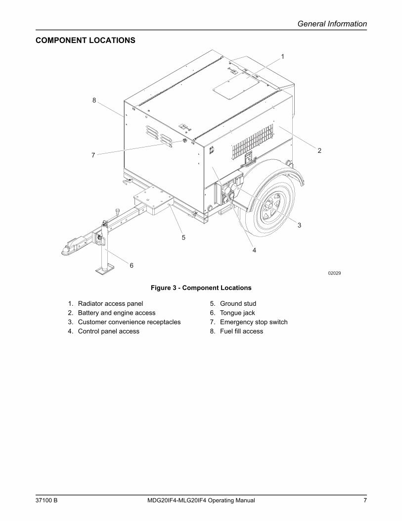
COMPONENT LOCATIONS
Figure 3 - Component Locations
1. Radiator access panel 5. Ground stud2. Battery and engine access 6. Tongue jack3. Customer convenience receptacles 7. Emergency stop switch4. Control panel access 8. Fuel fill access
02029
8
1
5
3
7
4
6
2
37100 B MDG20IF4-MLG20IF4 Operating Manual 7
General Information
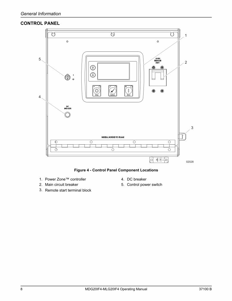
CONTROL PANEL
Figure 4 - Control Panel Component Locations
1. Power Zone™ controller 4. DC breaker2. Main circuit breaker 5. Control power switch3. Remote start terminal block
2
1
02028
5
4
3
Select
8 MDG20IF4-MLG20IF4 Operating Manual 37100 B
General Information
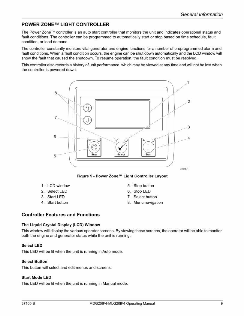
POWER ZONE™ LIGHT CONTROLLERThe Power Zone™ controller is an auto start controller that monitors the unit and indicates operational status and fault conditions. The controller can be programmed to automatically start or stop based on time schedule, fault condition, or load demand.
The controller constantly monitors vital generator and engine functions for a number of preprogrammed alarm and fault conditions. When a fault condition occurs, the engine can be shut down automatically and the LCD window will show the fault that caused the shutdown. To resume operation, the fault condition must be resolved.
This controller also records a history of unit performance, which may be viewed at any time and will not be lost when the controller is powered down.
Figure 5 - Power Zone™ Light Controller Layout
Controller Features and Functions
The Liquid Crystal Display (LCD) WindowThis window will display the various operator screens. By viewing these screens, the operator will be able to monitor both the engine and generator status while the unit is running.
Select LEDThis LED will be lit when the unit is running in Auto mode.
Select ButtonThis button will select and edit menus and screens.
Start Mode LEDThis LED will be lit when the unit is running in Manual mode.
1. LCD window 5. Stop button2. Select LED 6. Stop LED3. Start LED 7. Select button4. Start button 8. Menu navigation
Select
02017
1
2
3
4
5
6
7
8
37100 B MDG20IF4-MLG20IF4 Operating Manual 9
General Information
Start ModeThis button will start the engine, provided there are no shutdown errors, and the engine satisfies the start status.
Stop ModeThis button will shut down the unit and put the controller into Stop mode, whether in Manual mode or Auto mode.
CAUTIONIn case of an emergency, always press the emergency stop switch located on the front of the unit to stop the engine immediately. The Stop (O) button may delay the engine shutdown
if stop faults exist.
To prevent damage to the generator and connected equipment, remove all loads from the generator by opening all circuit breakers (turn to the OFF (O) position) before pressing the
Stop (O) button.
Stop Mode LEDThis LED will be lit when the unit is in Stop mode and will flash when an Electrical Trip and Shutdown Fault has occurred.
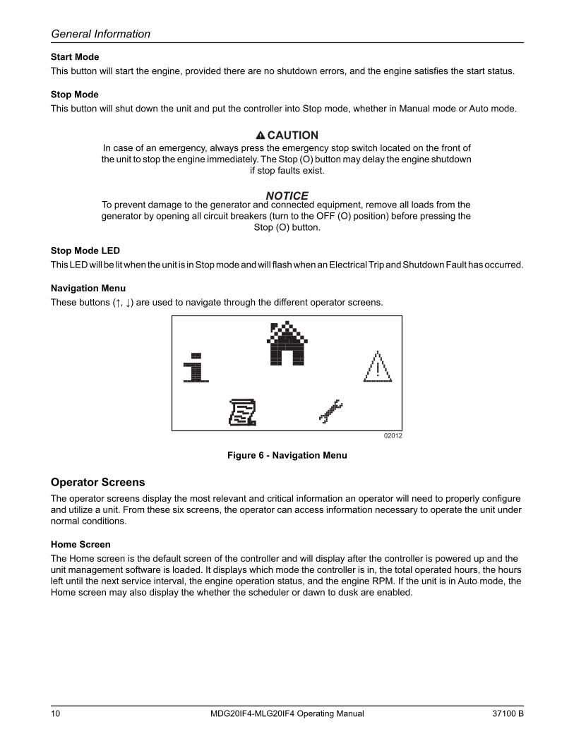
Navigation MenuThese buttons (↑, ↓) are used to navigate through the different operator screens.
Figure 6 - Navigation Menu
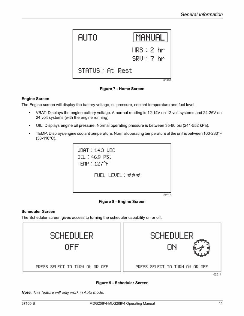
Operator ScreensThe operator screens display the most relevant and critical information an operator will need to properly configure and utilize a unit. From these six screens, the operator can access information necessary to operate the unit under normal conditions.
Home ScreenThe Home screen is the default screen of the controller and will display after the controller is powered up and the unit management software is loaded. It displays which mode the controller is in, the total operated hours, the hours left until the next service interval, the engine operation status, and the engine RPM. If the unit is in Auto mode, the Home screen may also display the whether the scheduler or dawn to dusk are enabled.
02012
10 MDG20IF4-MLG20IF4 Operating Manual 37100 B
General Information
Figure 7 - Home Screen
Engine ScreenThe Engine screen will display the battery voltage, oil pressure, coolant temperature and fuel level.
• VBAT: Displays the engine battery voltage. A normal reading is 12-14V on 12 volt systems and 24-26V on 24 volt systems (with the engine running).
• OIL: Displays engine oil pressure. Normal operating pressure is between 35-80 psi (241-552 kPa).
• TEMP: Displays engine coolant temperature. Normal operating temperature of the unit is between 100-230°F (38-110°C).
Figure 8 - Engine Screen
Scheduler ScreenThe Scheduler screen gives access to turning the scheduler capability on or off.
Figure 9 - Scheduler Screen
Note: This feature will only work in Auto mode.
AUTOAUTO MANUALMANUALHRS 2 hrSRV 7 hr
STATUS At Rest01968
VBAT 14.3 VDCOIL 46.9 PSITEMP 127°F
FUEL LEVEL
02016
SCHEDULER OFF
PRESS SELECT TO TURN ON OR OFF PRESS SELECT TO TURN ON OR OFF
02014
SCHEDULER ON
37100 B MDG20IF4-MLG20IF4 Operating Manual 11
General Information
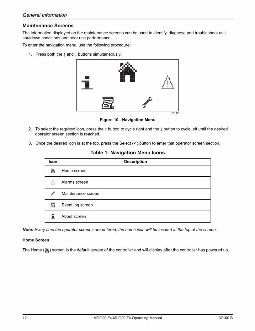
Maintenance ScreensThe information displayed on the maintenance screens can be used to identify, diagnose and troubleshoot unit shutdown conditions and poor unit performance.
To enter the navigation menu, use the following procedure:
1. Press both the ↑ and ↓ buttons simultaneously.
Figure 10 - Navigation Menu
2. To select the required icon, press the ↑ button to cycle right and the ↓ button to cycle left until the desired operator screen section is reached.
3. Once the desired icon is at the top, press the Select () button to enter that operator screen section.
Note: Every time the operator screens are entered, the home icon will be located at the top of the screen.
Home Screen
The Home ( ) screen is the default screen of the controller and will display after the controller has powered up.
Table 1: Navigation Menu IconsIcon Description
Home screen
Alarms screen
Maintenance screen
Event log screen
About screen
02012
12 MDG20IF4-MLG20IF4 Operating Manual 37100 B
General Information
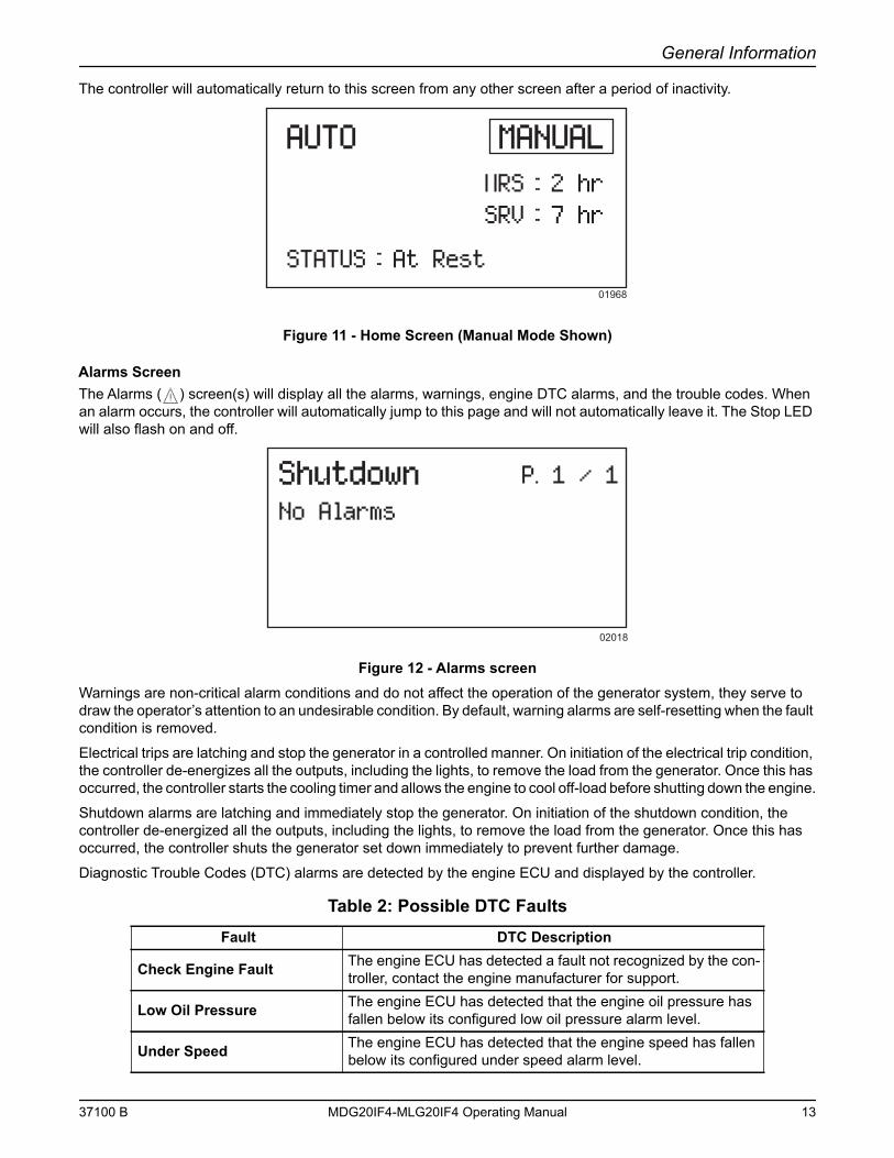
The controller will automatically return to this screen from any other screen after a period of inactivity.
Figure 11 - Home Screen (Manual Mode Shown)
Alarms ScreenThe Alarms ( ) screen(s) will display all the alarms, warnings, engine DTC alarms, and the trouble codes. When an alarm occurs, the controller will automatically jump to this page and will not automatically leave it. The Stop LED will also flash on and off.
Figure 12 - Alarms screenWarnings are non-critical alarm conditions and do not affect the operation of the generator system, they serve to draw the operator’s attention to an undesirable condition. By default, warning alarms are self-resetting when the fault condition is removed.
Electrical trips are latching and stop the generator in a controlled manner. On initiation of the electrical trip condition, the controller de-energizes all the outputs, including the lights, to remove the load from the generator. Once this has occurred, the controller starts the cooling timer and allows the engine to cool off-load before shutting down the engine.
Shutdown alarms are latching and immediately stop the generator. On initiation of the shutdown condition, the controller de-energized all the outputs, including the lights, to remove the load from the generator. Once this has occurred, the controller shuts the generator set down immediately to prevent further damage.
Diagnostic Trouble Codes (DTC) alarms are detected by the engine ECU and displayed by the controller.
Table 2: Possible DTC FaultsFault DTC Description
Check Engine Fault The engine ECU has detected a fault not recognized by the con-troller, contact the engine manufacturer for support.
Low Oil Pressure The engine ECU has detected that the engine oil pressure has fallen below its configured low oil pressure alarm level.
Under Speed The engine ECU has detected that the engine speed has fallen below its configured under speed alarm level.
AUTOAUTO MANUALMANUALHRS 2 hrSRV 7 hr
STATUS At Rest01968
ShutdownShutdownNo Alarms
P. 1 / 1
02018
37100 B MDG20IF4-MLG20IF4 Operating Manual 13
General Information
To view the active alarms, repeatedly press the ↑ and ↓ buttons until the LCD window displays the alarm.
Continue to press the ↑ and ↓ buttons will cycle through the alarms.
To exit the alarm screen, press the ↑ and ↓ buttons simultaneously to enter the navigation menu. Once entered, cycle to the desired operator screen.
Note: The alarm condition must be rectified before a reset will take place. If the alarm condition remains, it is not possible to reset the unit. The exception to this is the Low Oil Pressure alarm and similar ‘active from safety on’ alarms, as the oil pressure is low with the engine at rest.
To remove the fault of the latching alarms, refer to “Resetting the Maintenance Alarms”.
Note: The LCD backlight is on if the unit has sufficient voltage while the unit is turned on, unless the unit is cranking for which the backlight is turned off.
If the controller is left in Stop mode for a period of inactivity, the controller enters Power Save mode. To ‘wake’ the controller, press the Stop (O) button.
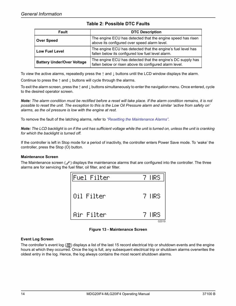
Maintenance ScreenThe Maintenance screen ( ) displays the maintenance alarms that are configured into the controller. The three alarms are for servicing the fuel filter, oil filter, and air filter.
Figure 13 - Maintenance Screen
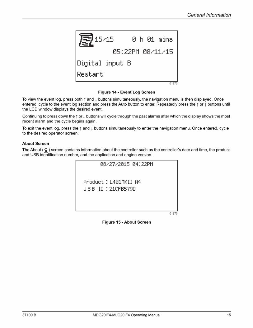
Event Log ScreenThe controller’s event log ( ) displays a list of the last 15 record electrical trip or shutdown events and the engine hours at which they occurred. Once the log is full, any subsequent electrical trip or shutdown alarms overwrites the oldest entry in the log. Hence, the log always contains the most recent shutdown alarms.
Over Speed The engine ECU has detected that the engine speed has risen above its configured over speed alarm level.
Low Fuel Level The engine ECU has detected that the engine’s fuel level has fallen below its configured low fuel level alarm.
Battery Under/Over Voltage The engine ECU has detected that the engine’s DC supply has fallen below or risen above its configured alarm level.
Table 2: Possible DTC FaultsFault DTC Description
Fuel Filter 7 HRS
Oil Filter 7 HRS
Air Filter 7 HRS02019
14 MDG20IF4-MLG20IF4 Operating Manual 37100 B
General Information
Figure 14 - Event Log ScreenTo view the event log, press both ↑ and ↓ buttons simultaneously, the navigation menu is then displayed. Once entered, cycle to the event log section and press the Auto button to enter. Repeatedly press the ↑ or ↓ buttons until the LCD window displays the desired event.
Continuing to press down the ↑ or ↓ buttons will cycle through the past alarms after which the display shows the most recent alarm and the cycle begins again.
To exit the event log, press the ↑ and ↓ buttons simultaneously to enter the navigation menu. Once entered, cycle to the desired operator screen.
About ScreenThe About ( ) screen contains information about the controller such as the controller’s date and time, the product and USB identification number, and the application and engine version.
Figure 15 - About Screen
15/15 0 h 01 mins
05 22PM 08/11/15
Digital input B
Restart01973
08/27/2015 04 22PM
Product L401MKII A4U ID 21CFB579D S B
01970
37100 B MDG20IF4-MLG20IF4 Operating Manual 15
General Information
This Page Intentionally Left Blank
16 MDG20IF4-MLG20IF4 Operating Manual 37100 B
Section 3 - Operation
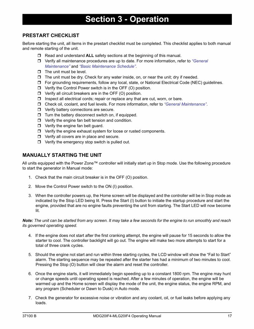
PRESTART CHECKLISTBefore starting the unit, all items in the prestart checklist must be completed. This checklist applies to both manual and remote starting of the unit.
Read and understand ALL safety sections at the beginning of this manual. Verify all maintenance procedures are up to date. For more information, refer to “General
Maintenance” and “Basic Maintenance Schedule”. The unit must be level. The unit must be dry. Check for any water inside, on, or near the unit; dry if needed. For grounding requirements, follow any local, state, or National Electrical Code (NEC) guidelines. Verify the Control Power switch is in the OFF (O) position. Verify all circuit breakers are in the OFF (O) position. Inspect all electrical cords; repair or replace any that are cut, worn, or bare. Check oil, coolant, and fuel levels. For more information, refer to “General Maintenance”. Verify battery connections are secure. Turn the battery disconnect switch on, if equipped. Verify the engine fan belt tension and condition. Verify the engine fan belt guard. Verify the engine exhaust system for loose or rusted components. Verify all covers are in place and secure. Verify the emergency stop switch is pulled out.
MANUALLY STARTING THE UNITAll units equipped with the Power Zone™ controller will initially start up in Stop mode. Use the following procedure to start the generator in Manual mode:
1. Check that the main circuit breaker is in the OFF (O) position.
2. Move the Control Power switch to the ON (I) position.
3. When the controller powers up, the Home screen will be displayed and the controller will be in Stop mode as indicated by the Stop LED being lit. Press the Start (I) button to initiate the startup procedure and start the engine, provided that are no engine faults preventing the unit from starting. The Start LED will now become lit.
Note: The unit can be started from any screen. It may take a few seconds for the engine to run smoothly and reach its governed operating speed.
4. If the engine does not start after the first cranking attempt, the engine will pause for 15 seconds to allow the starter to cool. The controller backlight will go out. The engine will make two more attempts to start for a total of three crank cycles.
5. Should the engine not start and run within three starting cycles, the LCD window will show the “Fail to Start” alarm. The starting sequence may be repeated after the starter has had a minimum of two minutes to cool. Pressing the Stop (O) button will clear the alarm and reset the controller.
6. Once the engine starts, it will immediately begin speeding up to a constant 1800 rpm. The engine may hunt or change speeds until operating speed is reached. After a few minutes of operation, the engine will be warmed up and the Home screen will display the mode of the unit, the engine status, the engine RPM, and any program (Scheduler or Dawn to Dusk) in Auto mode.
7. Check the generator for excessive noise or vibration and any coolant, oil, or fuel leaks before applying any loads.
37100 B MDG20IF4-MLG20IF4 Operating Manual 17
Operation
8. Check that the frequency (Hz) is correct on the Generator screen. With no loads connected to the generator, the frequency should read approximately 60 Hz, depending on the type of engine governing used.
9. If all wiring connections have been made correctly, switch the main circuit breaker to the ON (I) position and then add any loads attached to the receptacles by switching the respective circuit breaker to the ON (I) posi-tion. You will notice a slight change in engine sound when a load is applied to the unit.
10. Once the engine is running, allow it to reach normal operating temperature before switching on any loads.
AUTO (REMOTE) STARTING OF THE UNITAuto mode is used when the unit is started from a location other than the control panel by using a transfer switch. Auto (remote start) is the normal setting when the generator is being used as a standby power supply. Before putting the unit in the Auto mode, review the “Prestart Checklist” and “Manually Starting the Unit”. Also following any warnings and information on isolating the generator with a transfer switch if the unit is to be used as a standby power supply. Then continue with the steps described below:
1. Perform a manual start of the unit at least once to verify that the engine is operating correctly.
Note: The lights are automatically disconnected on startup. The main circuit breaker can be left on if no other loads are connected, except for the lights. Any connected external loads must be disconnected by a transfer switch when starting the unit.
2. If a check of the remove start circuit is desired:
a. Remove the wires from the remote start terminal block. Press the Select () button to select “AUTO.” The Select LED with be lit.
b. Attach a jumper wire (minimum 16 gauge) across the two terminals on the remote start terminal block. This applies a ground to the Power Zone™ Light controller to close the starting circuit contacts. The engine should crank, start and run.
c. Remove the jumper wire form the remote start terminal block and the engine will stop.
d. Reconnect any necessary wires form the remote start switch (transfer switch) to the remote start terminal block.
3. Confirm the unit is in Auto mode. The Select LED should be lit.
4. Secure the unit by closing and locking all access doors.
5. The unit is now ready for remote starting.
VOLTAGE REGULATORThe electronic voltage regulator controls the output of the generator by regulating the current into the exciter field. The regulator has three screwdriver adjustable potentiometers that may be adjusted for voltage, stability and voltage roll-off (U/F). The voltage regulator on your unit is adjusted before shipment from the factory. Contact Generac Mobile Products LLC for additional information before attempting to adjust the voltage regulator.
DERATING FOR ALTITUDEAll units are subject to derating for altitude and temperature; this will reduce the available power for operating tools and accessories connected to the receptacles. Typical reductions in performance are 2-4% for every 1000 ft (305 m) of elevation and 1% per 10ºF (5.6ºC) increase in ambient air temperature over 72ºF (22ºC).
WET STACKINGThe unit is powered by a diesel engine. Diesel engines are susceptible to wet stacking if lightly loaded. Wet stacking
18 MDG20IF4-MLG20IF4 Operating Manual 37100 B
Operation
occurs when an engine is run at less than 30% of its full load capacity, causing unburned fuel to accumulate in the exhaust system. Wet stacking can be detected by continuous black exhaust when the unit is under a constant load. It can also cause fouling of injectors and buildup on engine valves. Diesel engines operate properly when applied loads are between 30% and 100% capacity. Appropriate generator sizing is determined by the anticipated load. If the unit is in a wet stack condition, load the unit heavily for five hours or until the exhaust is clear.
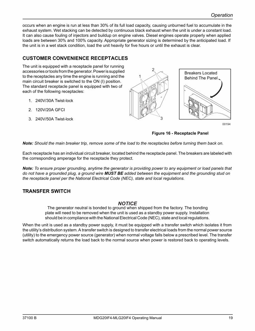
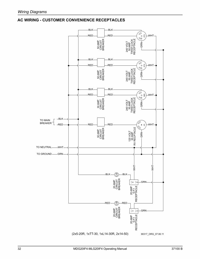
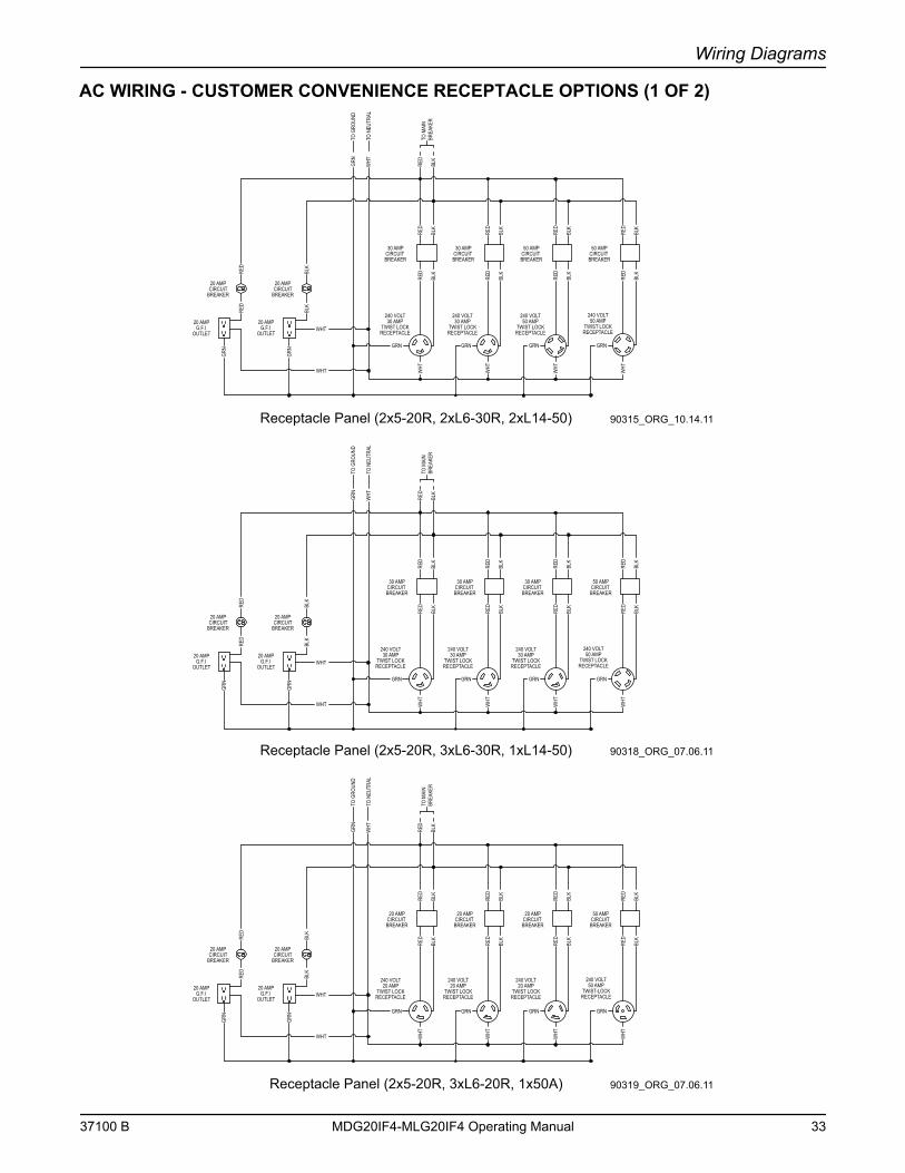
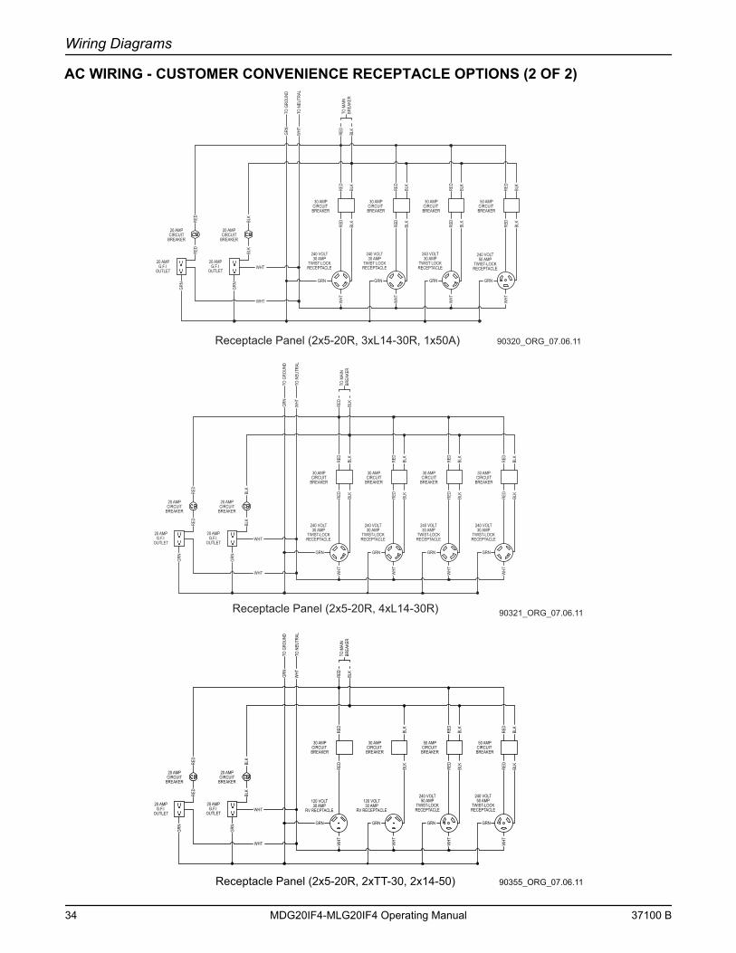
CUSTOMER CONVENIENCE RECEPTACLESThe unit is equipped with a receptacle panel for running accessories or tools from the generator. Power is supplied to the receptacles any time the engine is running and the main circuit breaker is switched to the ON (I) position. The standard receptacle panel is equipped with two of each of the following receptacles:
1. 240V/30A Twist-lock
2. 120V/20A GFCI
3. 240V/50A Twist-lock
Figure 16 - Receptacle Panel
Note: Should the main breaker trip, remove some of the load to the receptacles before turning them back on.
Each receptacle has an individual circuit breaker, located behind the receptacle panel. The breakers are labeled with the corresponding amperage for the receptacle they protect.
Note: To ensure proper grounding, anytime the generator is providing power to any equipment or load panels that do not have a grounded plug, a ground wire MUST BE added between the equipment and the grounding stud on the receptacle panel per the National Electrical Code (NEC), state and local regulations.
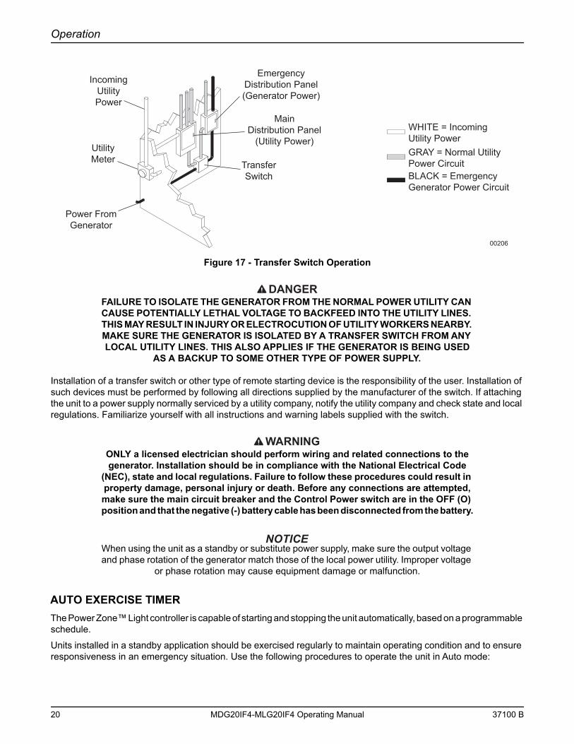
TRANSFER SWITCH
The generator neutral is bonded to ground when shipped from the factory. The bonding plate will need to be removed when the unit is used as a standby power supply. Installation should be in compliance with the National Electrical Code (NEC), state and local regulations.
When the unit is used as a standby power supply, it must be equipped with a transfer switch which isolates it from the utility’s distribution system. A transfer switch is designed to transfer electrical loads from the normal power source (utility) to the emergency power source (generator) when normal voltage falls below a prescribed level. The transfer switch automatically returns the load back to the normal source when power is restored back to operating levels.
Breakers LocatedBehind The Panel
21
300194
37100 B MDG20IF4-MLG20IF4 Operating Manual 19
Operation
Figure 17 - Transfer Switch Operation
DANGERFAILURE TO ISOLATE THE GENERATOR FROM THE NORMAL POWER UTILITY CAN CAUSE POTENTIALLY LETHAL VOLTAGE TO BACKFEED INTO THE UTILITY LINES. THIS MAY RESULT IN INJURY OR ELECTROCUTION OF UTILITY WORKERS NEARBY. MAKE SURE THE GENERATOR IS ISOLATED BY A TRANSFER SWITCH FROM ANY LOCAL UTILITY LINES. THIS ALSO APPLIES IF THE GENERATOR IS BEING USED
AS A BACKUP TO SOME OTHER TYPE OF POWER SUPPLY.
Installation of a transfer switch or other type of remote starting device is the responsibility of the user. Installation of such devices must be performed by following all directions supplied by the manufacturer of the switch. If attaching the unit to a power supply normally serviced by a utility company, notify the utility company and check state and local regulations. Familiarize yourself with all instructions and warning labels supplied with the switch.
WARNINGONLY a licensed electrician should perform wiring and related connections to the generator. Installation should be in compliance with the National Electrical Code
(NEC), state and local regulations. Failure to follow these procedures could result in property damage, personal injury or death. Before any connections are attempted, make sure the main circuit breaker and the Control Power switch are in the OFF (O) position and that the negative (-) battery cable has been disconnected from the battery.
When using the unit as a standby or substitute power supply, make sure the output voltage and phase rotation of the generator match those of the local power utility. Improper voltage
or phase rotation may cause equipment damage or malfunction.
AUTO EXERCISE TIMERThe Power Zone™ Light controller is capable of starting and stopping the unit automatically, based on a programmable schedule.
Units installed in a standby application should be exercised regularly to maintain operating condition and to ensure responsiveness in an emergency situation. Use the following procedures to operate the unit in Auto mode:
IncomingUtilityPower
UtilityMeter Transfer
Switch
MainDistribution Panel
(Utility Power)
EmergencyDistribution Panel(Generator Power)
Power FromGenerator
WHITE = IncomingUtility PowerGRAY = Normal UtilityPower CircuitBLACK = EmergencyGenerator Power Circuit
00206
20 MDG20IF4-MLG20IF4 Operating Manual 37100 B
Operation
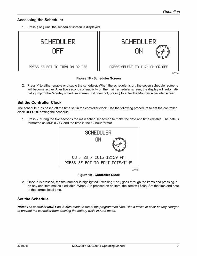
Accessing the Scheduler
1. Press ↑ or ↓ until the scheduler screen is displayed.
Figure 18 - Scheduler Screen
2. Press to either enable or disable the scheduler. When the scheduler is on, the seven scheduler screens will become active. After five seconds of inactivity on the main scheduler screen, the display will automati-cally jump to the Monday scheduler screen. If it does not, press ↓ to enter the Monday scheduler screen.
Set the Controller ClockThe schedule runs based off the time set in the controller clock. Use the following procedure to set the controller clock BEFORE setting the schedule:
1. Press during the five seconds the main scheduler screen to make the date and time editable. The date is formatted as MM/DD/YY and the time in the 12 hour format.
Figure 19 - Controller Clock
2. Once is pressed, the first number is highlighted. Pressing ↑ or ↓ goes through the items and pressing on any one item makes it editable. When is pressed on an item, the item will flash. Set the time and date to the correct local time.
Set the Schedule
Note: The controller MUST be in Auto mode to run at the programmed time. Use a trickle or solar battery charger to prevent the controller from draining the battery while in Auto mode.
SCHEDULER OFF
PRESS SELECT TO TURN ON OR OFF PRESS SELECT TO TURN ON OR OFF
02014
SCHEDULER ON
SCHEDULERSCHEDULERONON
08 / 28 / 2015 12 29 PMPRESS SELECT TO EDIT DATE/TIME
02013
37100 B MDG20IF4-MLG20IF4 Operating Manual 21
Operation
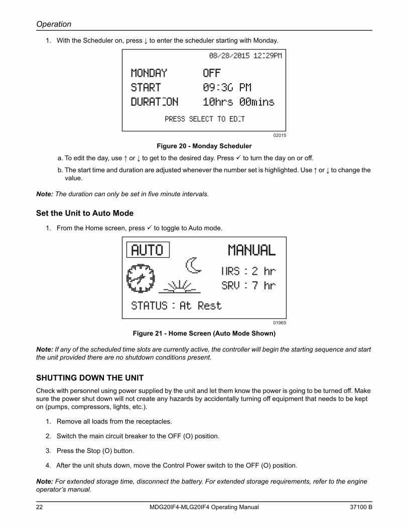
1. With the Scheduler on, press ↓ to enter the scheduler starting with Monday.
Figure 20 - Monday Scheduler
a. To edit the day, use ↑ or ↓ to get to the desired day. Press to turn the day on or off.
b. The start time and duration are adjusted whenever the number set is highlighted. Use ↑ or ↓ to change the value.
Note: The duration can only be set in five minute intervals.
Set the Unit to Auto Mode
1. From the Home screen, press to toggle to Auto mode.
Figure 21 - Home Screen (Auto Mode Shown)
Note: If any of the scheduled time slots are currently active, the controller will begin the starting sequence and start the unit provided there are no shutdown conditions present.
SHUTTING DOWN THE UNITCheck with personnel using power supplied by the unit and let them know the power is going to be turned off. Make sure the power shut down will not create any hazards by accidentally turning off equipment that needs to be kept on (pumps, compressors, lights, etc.).
1. Remove all loads from the receptacles.
2. Switch the main circuit breaker to the OFF (O) position.
3. Press the Stop (O) button.
4. After the unit shuts down, move the Control Power switch to the OFF (O) position.
Note: For extended storage time, disconnect the battery. For extended storage requirements, refer to the engine operator’s manual.
08/28/2015 12 29PM
MONDAYMONDAY OFFOFFSTARTSTART 09 36 PMDURATIONDURATION 10hrs 00mins
PRESS SELECT TO EDIT
02015
AUTOAUTO MANUALMANUALHRS 2 hrSRV 7 hr
STATUS At Rest01969
22 MDG20IF4-MLG20IF4 Operating Manual 37100 B
Operation
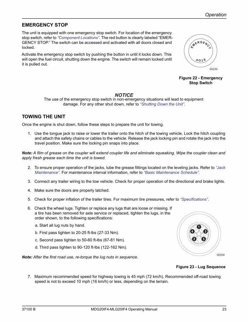
EMERGENCY STOPThe unit is equipped with one emergency stop switch. For location of the emergency stop switch, refer to “Component Locations”. The red button is clearly labeled “EMER-GENCY STOP.” The switch can be accessed and activated with all doors closed and locked.
Activate the emergency stop switch by pushing the button in until it locks down. This will open the fuel circuit, shutting down the engine. The switch will remain locked until it is pulled out.
Figure 22 - Emergency Stop Switch
The use of the emergency stop switch in non-emergency situations will lead to equipment damage. For any other shut down, refer to “Shutting Down the Unit”.
TOWING THE UNITOnce the engine is shut down, follow these steps to prepare the unit for towing.
1. Use the tongue jack to raise or lower the trailer onto the hitch of the towing vehicle. Lock the hitch coupling and attach the safety chains or cables to the vehicle. Release the jack locking pin and rotate the jack into the travel position. Make sure the locking pin snaps into place.
Note: A film of grease on the coupler will extend coupler life and eliminate squeaking. Wipe the coupler clean and apply fresh grease each time the unit is towed.
2. To ensure proper operation of the jacks, lube the grease fittings located on the leveling jacks. Refer to “Jack Maintenance”. For maintenance interval information, refer to “Basic Maintenance Schedule”.
3. Connect any trailer wiring to the tow vehicle. Check for proper operation of the directional and brake lights.
4. Make sure the doors are properly latched.
5. Check for proper inflation of the trailer tires. For maximum tire pressures, refer to “Specifications”.
6. Check the wheel lugs. Tighten or replace any lugs that are loose or missing. If a tire has been removed for axle service or replaced, tighten the lugs, in the order shown, to the following specifications:
a. Start all lug nuts by hand.
b. First pass tighten to 20-25 ft-lbs (27-33 Nm).
c. Second pass tighten to 50-60 ft-lbs (67-81 Nm).
d. Third pass tighten to 90-120 ft-lbs (122-162 Nm).
Note: After the first road use, re-torque the lug nuts in sequence.
Figure 23 - Lug Sequence
7. Maximum recommended speed for highway towing is 45 mph (72 km/h). Recommended off-road towing speed is not to exceed 10 mph (16 km/h) or less, depending on the terrain.
STOP
E
MERGENCY
00230
52
341
00204
37100 B MDG20IF4-MLG20IF4 Operating Manual 23
Operation
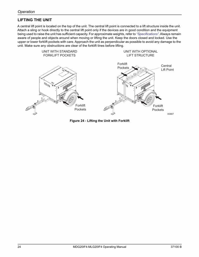
LIFTING THE UNITA central lift point is located on the top of the unit. The central lift point is connected to a lift structure inside the unit. Attach a sling or hook directly to the central lift point only if the devices are in good condition and the equipment being used to raise the unit has sufficient capacity. For approximate weights, refer to “Specifications”. Always remain aware of people and objects around when moving or lifting the unit. Keep the doors closed and locked. Use the upper or lower forklift pockets with care. Approach the unit as perpendicular as possible to avoid any damage to the unit. Make sure any obstructions are clear of the forklift tines before lifting.
Figure 24 - Lifting the Unit with Forklift
00887
UNIT WITH STANDARDFORKLIFT POCKETS
UNIT WITH OPTIONALLIFT STRUCTURE
CentralLift Point
ForkliftPockets
ForkliftPockets
ForkliftPockets
24 MDG20IF4-MLG20IF4 Operating Manual 37100 B
Section 4 - Maintenance
Normal maintenance service and replacement of parts are the responsibility of the owner/operator and, as such, are not considered defects in materials or workmanship within the terms of the warranty. It is strongly recommended that the equipment be periodically checked by a Generac Mobile Products Authorized Dealer.
DAILY WALK AROUND INSPECTIONLook for conditions that could hinder performance or safety, such as (but not limited to) oil/coolant/fuel leakage, blocked vents, loose/missing hardware, and electrical connections.
Visually inspect the fan belt for cracks, fraying, stretching, and verify the belt is properly seated in the pulley grooves. Replace the belt according to the manufacturer’s recommendations.
Note: At the 500 hour/12 month service interval, it is recommended that the belt be removed and checked for wear. While the belt is removed, inspect pulleys and bearings. Rotate and feel for hard turning or unusual sounds. If pulleys or bearings need replacement, contact the engine manufacturer.
Failure to perform a daily inspection may result in serious damage to the prime mover.
GENERAL MAINTENANCEPoorly maintained equipment can become a safety hazard. In order for the equipment to operate safely and properly over a long period of time, periodic maintenance and occasional repairs are necessary. NEVER perform routine service (oil/filter changes, cleaning, etc.) unless all electrical components are shut off. Before servicing the unit, always follow the instructions listed below.
• Verify the Control Power switch is turned to the OFF (O) position.
• Verify the circuit breakers are turned to the OFF (O) position.
• Activate (push in) the emergency stop switch.
• Disconnect the negative (-) terminal on the battery.
• Attach a “Do Not Start” sign to the control panel. This will notify everyone that the unit is being serviced and will reduce the chance of someone inadvertently trying to start the unit.
• Never wash the unit with a high pressure hose or with any kind of power washer.
• Never wash the engine block or fuel tank with a power washer or steam cleaner. Water may enter the cabinet and collect in the generator windings or other electrical parts, causing damage.
• If the unit is stored outside, check for water inside the cabinet and generator before each use. If wet, dry the unit thoroughly before starting.
• Inspect condition of electrical cords. DO NOT use the unit if insulation is cut or worn through.
• Check the wheel lugs. Refer to “Towing the Unit”.
• Check the coolant level daily. Refer to the engine operator’s manual for coolant recommendations and proper mixture.○ Coolant is checked visually by inspecting the level in coolant overflow jug located near the radiator.○ Normal operating level is between the full and add markings on the overflow jug known as normal range.○ WHEN ENGINE IS STOPPED AND COMPLETELY COOL, coolant may be added directly to the coolant overflow jug.
• Check the oil level daily. Refer to the engine operator’s manual for the proper viscosity grade of oil, including special operating conditions such as a change in season or climate.○ DO NOT start the unit if the engine oil level is below the add mark on the dipstick.
37100 B MDG20IF4-MLG20IF4 Operating Manual 25
Maintenance
○ Normal operating level is in the cross-hatch pattern between the full and add markings on the dipstick.○ Add oil only if the oil level is below the add mark on the bottom of the cross-hatch pattern on the dipstick. DO NOT OVERFILL the crankcase.
• Check the fuel level.
• If the unit is connected to a remote start or transfer switch, make sure the remote switch is also off and tagged.
Note: If the engine was run out of fuel or the fuel tank was drained, it may be necessary to bleed the fuel lines. Refer to the engine operator’s manual supplied with the unit.
BASIC MAINTENANCE SCHEDULE
Refer to the original equipment manufacturer’s operating manual for a complete list of maintenance requirements. Failure to comply with the procedures as described in the engine operator’s manual will nullify the warranty, decrease performance and cause equipment
damage or premature equipment failure. Maintenance records may be required to complete a warranty request.
Use the schedule in the following table as a guide for regular maintenance intervals.
* If the unit is operated in a harsh environment or fuel quality is questioned, replace every 250 hours instead of every 500 hours.
RESETTING THE MAINTENANCE ALARMSThe Power Zone™ Light controller will display a warning message when the unit is due for maintenance or service.
Table 3: Isuzu Engine Maintenance Schedule
Item Daily
50 Hours (Break-In
Period Only)
250 Hours
500Hours
Check Oil Level ♦Check Coolant Level ♦Check Fuel Level ♦Drain Fuel Filter ♦Check Tire Pressure ♦Check All Electrical Connections ♦Clean Battery ♦Check Fan Belt Tension (Replace If Necessary) ♦ ♦Inspect Radiator Fins For Debris, Clean As Required ♦Preheating Condition Check ♦Check Engine Starting Conditions and Noise Conditions ♦Check Exhaust Smoke Condition ♦Replace Engine Oil ♦ ♦Replace Fuel Filter Element ♦*Clean Water Sedimenter Element ♦*Electromagnetic Pump Filter Replacement Or Cleaning ♦*Oil Filter Element Replacement ♦ ♦Replace Air Filter Element ♦Lubricate Leveling Jacks ♦
26 MDG20IF4-MLG20IF4 Operating Manual 37100 B
Maintenance
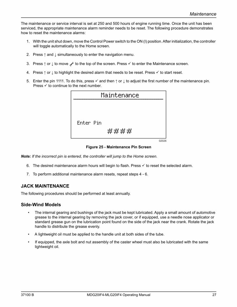
The maintenance or service interval is set at 250 and 500 hours of engine running time. Once the unit has been serviced, the appropriate maintenance alarm reminder needs to be reset. The following procedure demonstrates how to reset the maintenance alarms:
1. With the unit shut down, move the Control Power switch to the ON (I) position. After initialization, the controller will toggle automatically to the Home screen.
2. Press ↑ and ↓ simultaneously to enter the navigation menu.
3. Press ↑ or ↓ to move to the top of the screen. Press to enter the Maintenance screen.
4. Press ↑ or ↓ to highlight the desired alarm that needs to be reset. Press to start reset.
5. Enter the pin 1111. To do this, press and then ↑ or ↓ to adjust the first number of the maintenance pin. Press to continue to the next number.
Figure 25 - Maintenance Pin Screen
Note: If the incorrect pin is entered, the controller will jump to the Home screen.
6. The desired maintenance alarm hours will begin to flash. Press to reset the selected alarm.
7. To perform additional maintenance alarm resets, repeat steps 4 - 6.
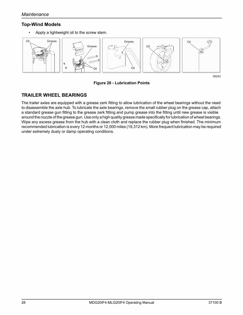
JACK MAINTENANCEThe following procedures should be performed at least annually.
Side-Wind Models• The internal gearing and bushings of the jack must be kept lubricated. Apply a small amount of automotive
grease to the internal gearing by removing the jack cover, or if equipped, use a needle nose applicator or standard grease gun on the lubrication point found on the side of the jack near the crank. Rotate the jack handle to distribute the grease evenly.
• A lightweight oil must be applied to the handle unit at both sides of the tube.
• If equipped, the axle bolt and nut assembly of the caster wheel must also be lubricated with the same lightweight oil.
Enter Pin
Maintenance
02026
37100 B MDG20IF4-MLG20IF4 Operating Manual 27
Maintenance
Top-Wind Models• Apply a lightweight oil to the screw stem.
Figure 26 - Lubrication Points
TRAILER WHEEL BEARINGSThe trailer axles are equipped with a grease zerk fitting to allow lubrication of the wheel bearings without the need to disassemble the axle hub. To lubricate the axle bearings, remove the small rubber plug on the grease cap, attach a standard grease gun fitting to the grease zerk fitting and pump grease into the fitting until new grease is visible around the nozzle of the grease gun. Use only a high quality grease made specifically for lubrication of wheel bearings. Wipe any excess grease from the hub with a clean cloth and replace the rubber plug when finished. The minimum recommended lubrication is every 12 months or 12,000 miles (19,312 km). More frequent lubrication may be required under extremely dusty or damp operating conditions.
Oil Grease
GreaseGrease
Oil Oil
OilOil
00243
28 MDG20IF4-MLG20IF4 Operating Manual 37100 B
Section 5 - Troubleshooting
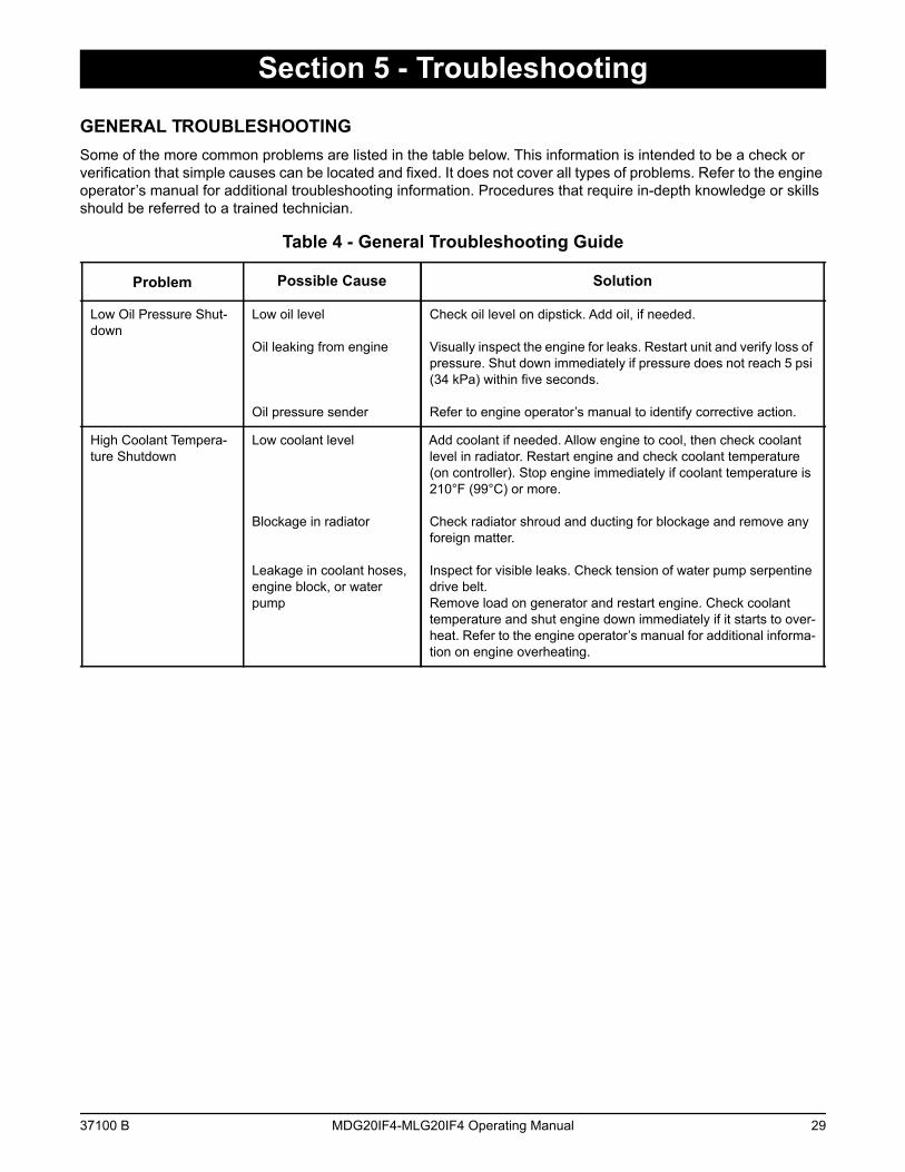
GENERAL TROUBLESHOOTINGSome of the more common problems are listed in the table below. This information is intended to be a check or verification that simple causes can be located and fixed. It does not cover all types of problems. Refer to the engine operator’s manual for additional troubleshooting information. Procedures that require in-depth knowledge or skills should be referred to a trained technician.
Table 4 - General Troubleshooting Guide
Problem Possible Cause Solution
Low Oil Pressure Shut-down
Low oil level
Oil leaking from engine
Oil pressure sender
Check oil level on dipstick. Add oil, if needed.
Visually inspect the engine for leaks. Restart unit and verify loss of pressure. Shut down immediately if pressure does not reach 5 psi (34 kPa) within five seconds.
Refer to engine operator’s manual to identify corrective action.
High Coolant Tempera-ture Shutdown
Low coolant level
Blockage in radiator
Leakage in coolant hoses, engine block, or water pump
Add coolant if needed. Allow engine to cool, then check coolant level in radiator. Restart engine and check coolant temperature (on controller). Stop engine immediately if coolant temperature is 210°F (99°C) or more.
Check radiator shroud and ducting for blockage and remove any foreign matter.
Inspect for visible leaks. Check tension of water pump serpentine drive belt.Remove load on generator and restart engine. Check coolant temperature and shut engine down immediately if it starts to over-heat. Refer to the engine operator’s manual for additional informa-tion on engine overheating.
37100 B MDG20IF4-MLG20IF4 Operating Manual 29

Troubleshooting
This Page Intentionally Left Blank
30 MDG20IF4-MLG20IF4 Operating Manual 37100 B
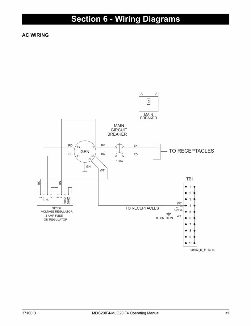
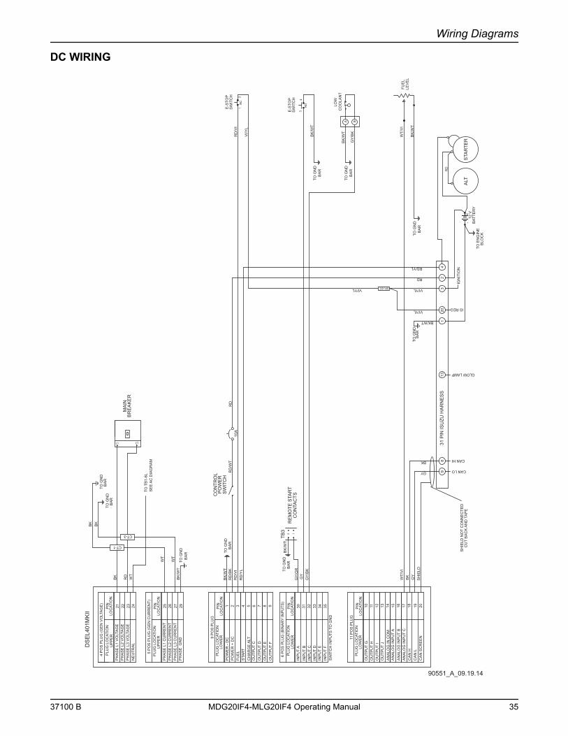
Section 6 - Wiring Diagrams
AC WIRING
GEN
MAIN CIRCUIT
BREAKER
100A
L1
L2
1
2
3
4
5
6
7
8
9
10
TO RECEPTACLES
TB1
BK
RD
WTGN
RDF-
F+
N
60H
Z50
HZ
ON REGULATOR4 AMP FUSE
F-F+3 467
SE350VOLTAGE REGULATOR
BNBK
RD
BL
BK
TO RECEPTACLES
TO CNTRL 24
WT
GN/YL
WT
L2 L1
MAINBREAKER
90552_B_11.13.14
37100 B MDG20IF4-MLG20IF4 Operating Manual 31
Wiring Diagrams
AC WIRING - CUSTOMER CONVENIENCE RECEPTACLES
(2x5-20R, 1xTT-30, 1xL14-30R, 2x14-50)
120
VO
LT30
AM
PR
V R
EC
PTA
CLE
20 A
MP
CIR
CU
ITB
RE
AK
ER
20 A
MP
CIR
CU
ITB
RE
AK
ER
20 A
MP
G.F
.I R
EC
EP
TAC
LE
20 A
MP
G.F
.I R
EC
EP
TAC
LE
TO GROUND
TO NEUTRAL
TO MAINBREAKER
RED
BLK BLK
RED
WH
T
WH
T
GRN
GRN
GRN
WHT
RED
BLK
RED RED
BLKBLK
REDRED
REDRED
BLK BLK
BLK BLK
GR
N
WHT
GR
NG
RN
GR
N
WHT
WHT
WHT
240
VO
LT50
AM
PTW
IST-
LOC
KR
EC
EP
TAC
LER
EC
EP
TAC
LE
240
VO
LT50
AM
PTW
IST-
LOC
K
30 A
MP
CIR
CU
IT
BR
EA
KE
R
30 A
MP
CIR
CU
IT
BR
EA
KE
RB
RE
AK
ER
CIR
CU
IT
50 A
MP
BR
EA
KE
RC
IRC
UIT
50
AM
PREDRED
240
VO
LT30
AM
PTW
IST-
LOC
KR
EC
EP
TAC
LE
90317_ORG_07.06.11
32 MDG20IF4-MLG20IF4 Operating Manual 37100 B
Wiring Diagrams
AC WIRING - CUSTOMER CONVENIENCE RECEPTACLE OPTIONS (1 OF 2)
Receptacle Panel (2x5-20R, 2xL6-30R, 2xL14-50) 90315_ORG_10.14.11
240 VOLT30 AMP
TWIST LOCKRECEPTACLE
20 AMPCIRCUIT
BREAKER
20 AMPCIRCUIT
BREAKER
20 AMPG.F.I
OUTLET
20 AMPG.F.I
OUTLET
30 AMPCIRCUIT BREAKER
30 AMPCIRCUIT BREAKER
50 AMPCIRCUIT BREAKER
50 AMPCIRCUIT BREAKER
TO G
ROUN
D
TO N
EUTR
AL
TO M
AIN
BREA
KER
RED
BLK
BLK
RED
WHT
WHT
GRN
GRN
GRN
WHT RED
BLK
RED
RED
RED
RED
RED
RED
RED
RED
BLK
BLK
BLK
BLK
GRN
WHT
GRN GRN GRN
WHT
WHT
WHT
BLK
BLK
BLK
BLK
240 VOLT50 AMP
TWIST LOCKRECEPTACLE
240 VOLT30 AMP
TWIST LOCKRECEPTACLE
240 VOLT50 AMP
TWIST LOCKRECEPTACLE
Receptacle Panel (2x5-20R, 3xL6-30R, 1xL14-50) 90318_ORG_07.06.11
240 VOLT30 AMP
TWIST LOCKRECEPTACLE
20 AMPCIRCUIT
BREAKER
20 AMPCIRCUIT
BREAKER
20 AMPG.F.I
OUTLET
20 AMPG.F.I
OUTLET
30 AMPCIRCUIT BREAKER
30 AMPCIRCUIT BREAKER
30 AMPCIRCUIT BREAKER
50 AMPCIRCUIT BREAKER
TO G
ROUN
D
TO N
EUTR
AL
TO M
AIN
BREA
KER
RED
BLK
BLK
RED
WHT
WHT
GRN
GRN
GRN
WHT RED
BLK
RED
RED
RED
RED
RED
RED
RED
RED
BLK
BLK
BLK
BLK
GRN
WHT
GRN GRN GRN
WHT
WHT
WHT
BLK
BLK
BLK
BLK
240 VOLT50 AMP
TWIST LOCKRECEPTACLE
240 VOLT30 AMP
TWIST LOCKRECEPTACLE
240 VOLT30 AMP
TWIST LOCKRECEPTACLE
Receptacle Panel (2x5-20R, 3xL6-20R, 1x50A) 90319_ORG_07.06.11
240 VOLT20 AMP
TWIST LOCKRECEPTACLE
20 AMPCIRCUIT
BREAKER
20 AMPCIRCUIT
BREAKER
20 AMPG.F.I
OUTLET
20 AMPG.F.I
OUTLET
20 AMPCIRCUIT BREAKER
20 AMPCIRCUIT BREAKER
20 AMPCIRCUIT BREAKER
50 AMPCIRCUIT BREAKER
TO G
ROUN
D
TO N
EUTR
AL
TO M
AIN
BREA
KER
RED
BLK
BLK
RED
WHT
WHT
GRN
GRN
GRN
WHT RED
BLK
RED
RED
RED
RED
RED
RED
RED
RED
BLK
BLK
BLK
BLK
GRN
WHT
GRN GRN GRN
WHT
WHT
WHT
BLK
BLK
BLK
BLK
RECEPTACLE
240 VOLT50 AMP
TWIST-LOCK
240 VOLT20 AMP
TWIST LOCKRECEPTACLE
240 VOLT20 AMP
TWIST LOCKRECEPTACLE
37100 B MDG20IF4-MLG20IF4 Operating Manual 33
Wiring Diagrams
AC WIRING - CUSTOMER CONVENIENCE RECEPTACLE OPTIONS (2 OF 2)
Receptacle Panel (2x5-20R, 3xL14-30R, 1x50A) 90320_ORG_07.06.11
240 VOLT30 AMP
TWIST LOCKRECEPTACLE
20 AMPCIRCUIT
BREAKER
20 AMPCIRCUIT
BREAKER
20 AMPG.F.I
OUTLET
20 AMPG.F.I
OUTLET
30 AMPCIRCUIT BREAKER
30 AMPCIRCUIT BREAKER
30 AMPCIRCUIT BREAKER
50 AMPCIRCUIT BREAKER
TO G
ROUN
D
TO N
EUTR
AL
TO M
AIN
BREA
KER
RED
BLK
BLK
RED
WHT
WHT
GRN
GRN
GRN
WHT RED
BLK
RED
RED
RED
RED
RED
RED
RED
RED
BLK
BLK
BLK
BLK
GRN
WHT
GRN GRN GRN
WHT
WHT
WHT
BLK
BLK
BLK
BLK
240 VOLT30 AMP
TWIST LOCKRECEPTACLE
240 VOLT30 AMP
TWIST LOCKRECEPTACLE RECEPTACLE
240 VOLT50 AMP
TWIST-LOCK
Receptacle Panel (2x5-20R, 4xL14-30R) 90321_ORG_07.06.11
20 AMPCIRCUIT
BREAKER
20 AMPCIRCUIT
BREAKER
20 AMPG.F.I
OUTLET
20 AMPG.F.I
OUTLET
TO G
ROUN
D
TO N
EUTR
AL
TO M
AIN
BREA
KER
RED
BLK
BLK
RED
WHT
WHT
GRN
GRN
GRN
WHT RED
BLK
RED
RED
BLK
BLK
RED
RED
RED
RED
BLK
BLK
BLK
BLK
GRN
WHT
GRN GRN GRN
WHT
WHT
WHT
240 VOLT30 AMP
TWIST-LOCKRECEPTACLE
BLK
BLK
RED
RED
240 VOLT30 AMP
TWIST-LOCKRECEPTACLE
240 VOLT30 AMP
TWIST-LOCKRECEPTACLE
240 VOLT30 AMP
TWIST-LOCKRECEPTACLE
30 AMPCIRCUIT
BREAKER
30 AMPCIRCUIT
BREAKER
30 AMPCIRCUIT
BREAKER
30 AMPCIRCUIT
BREAKER
Receptacle Panel (2x5-20R, 2xTT-30, 2x14-50) 90355_ORG_07.06.11
120 VOLT30 AMP
RV RECPTACLE
120 VOLT30 AMP
RV RECEPTACLE
20 AMPCIRCUIT
BREAKER
20 AMPCIRCUIT
BREAKER
20 AMPG.F.I
OUTLET
20 AMPG.F.I
OUTLET
TO G
ROUN
D
TO N
EUTR
AL
TO M
AIN
BREA
KER
RED
BLK
BLK
RED
WHT
WHT
GRN
GRN
GRN
WHT RED
BLK
RED
RED
BLK
BLK
RED
RED
RED
RED
BLK
BLK
BLK
BLK
GRN
WHT
GRN GRN GRN
WHT
WHT
WHT
240 VOLT50 AMP
TWIST-LOCKRECEPTACLE RECEPTACLE
240 VOLT50 AMP
TWIST-LOCK
30 AMPCIRCUIT BREAKER
30 AMPCIRCUIT BREAKER BREAKER
CIRCUIT 50 AMP
BREAKERCIRCUIT 50 AMP
34 MDG20IF4-MLG20IF4 Operating Manual 37100 B
Wiring Diagrams
DC WIRING
A B
PO
WE
R +
DC
PLU
G L
OC
ATIO
N
PO
WE
R -
DC
1
9 P
OS
PLU
G
2
LOW
ER
INP
UT
A30
6 P
OS
PLU
G (B
INA
RY
INP
UTS
)
STA
RT
4
CO
NTR
OL
PO
WE
RS
WIT
CH
RD
/BK
BK
/WT
4 P
OS
PLU
G (G
EN
VO
LTA
GE
)
PH
AS
E L
1 V
OLT
AG
EP
HA
SE
L2
VO
LTA
GE
PH
AS
E L
3 V
OLT
AG
E
21
PLU
G L
OC
ATIO
N
NE
UTR
AL
22 23 24
PH
AS
E L
3 C
UR
RE
NT
PH
AS
E L
2 C
UR
RE
NT
PH
AS
E L
1 C
UR
RE
NT
5 P
OS
PLU
G (G
EN
CU
RR
EN
T)P
LUG
LO
CAT
ION
272625
PH
AS
E G
ND
29
PLU
G L
OC
ATIO
N
DS
EL4
01M
KII
GY
/OR
RD/YL
BK
/WT
TB3
2 1R
EM
OTE
STA
RT
CO
NTA
CTS
INP
UT
B31 32 33 34 35
INP
UT
EIN
PU
T F
INP
UT
C
6O
UTP
UT
CC
HA
RG
E A
LT
OU
TPU
T D
8 9
INP
UT
D
OU
TPU
T F
75
SH
IELD
BK
GY
BK
UP
PE
R
UP
PE
R
LOW
ER
GY
BK/WT
RD
OU
TPU
T E
FUE
L3
SW
ITC
H IN
PU
TS T
O G
ND
PIN
LOC
ATIO
N
PIN
LOC
ATIO
N
PIN
LOC
ATIO
N
PIN
LOC
ATIO
N
TO G
ND
BA
R
BA
RTO
GN
D
TO G
ND
BA
R
FUE
LLE
VE
L
BA
RTO
GN
DB
K/W
T
VI/YL
RD
/WT
SPLICE
LOW
C
OO
LAN
T
BA
RTO
GN
D
GY
/BK
OU
TPU
T H
PLU
G L
OC
ATIO
N
OU
TPU
T G
10
11 P
OS
PLU
G
11
OU
TPU
T J
13 15A
NA
LOG
INP
UT
AA
NA
LOG
IN C
OM
AN
ALO
G IN
PU
T B
17 18 19 20
CA
N H
CA
N L
CA
N S
CR
EE
N
1614
LOW
ER
AN
ALO
G IN
PU
T C
OU
TPU
T I
12PIN
LOC
ATIO
N
10A
WT/
VI
WT/
VI
21
NC
E-S
TOP
SW
ITC
HR
D/V
IR
D/V
I
GY
NO
34
E-S
TOP
SW
ITC
H
BK
/WT
BA
RTO
GN
D
RD
/YL
RD
12 V
-+
BAT
TER
Y
STA
RTE
RS
HIE
LD N
OT
CO
NN
EC
TED
CU
T B
AC
K A
ND
TA
PE
ALT
RD
TO E
NG
INE
IGN
ITIO
N
GLOW LAMP
CAN HI
CAN LO
131
32
49
831
PIN
ISU
ZU H
AR
NE
SS
20
IS REG
BLO
CK
BK
/WT
GY
/BK
VI/Y
L
VI/YL
VI/YL
BK
/WT
WT
RD
BK
WT
CT-1
CT-3
WT
BK BK
L3L1
MA
INB
RE
AK
ER
BA
RTO
GN
D
BA
RTO
GN
D
BA
RTO
GN
D
TO T
B1-
6LS
EE
AC
DIA
GR
AM
90551_A_09.19.14
37100 B MDG20IF4-MLG20IF4 Operating Manual 35
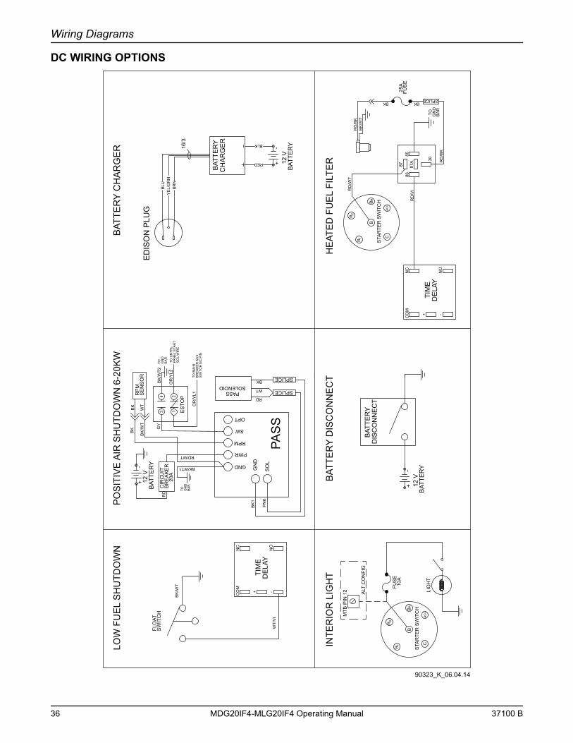
Wiring Diagrams
DC WIRING OPTIONS
YE
L/G
RN
BLU
BR
N
16/3
ED
ISO
N P
LUG
-+
BAT
TER
Y12
V
RED
BLK
12 V
BAT
TER
Y+
-
CH
AR
GE
RB
ATTE
RY
BAT
TER
YD
ISC
ON
NE
CT
LIG
HT
STA
RTE
R S
WIT
CH
FUS
E
INTE
RIO
R L
IGH
T B
ATTE
RY
DIS
CO
NN
EC
T
BAT
TER
Y C
HA
RG
ER
BK
/WT
RD
/BK
BK
STA
RTE
R S
WIT
CH
HE
ATE
D F
UE
L FI
LTE
R 30
8586
87A
87FU
SE
RD
/WT
RD
/VI
TO GN
DB
AR
25A
RD
/BK
10A
MTB
PIN
12 ALT
CO
NFI
G
PO
SIT
IVE
AIR
SH
UTD
OW
N 6
-20K
WB
K
WT
RP
MS
EN
SO
R
PAS
SGND
PWR
RPM
SW
OPT
GN
D
SO
L
CIR
CU
ITB
RE
AK
ER
20A
-+
BAT
TER
Y12
V
ES
TOP
SOLENOIDPASS
RD
WT
BK SPLICE
SPLICE
RD
RD/WT
BK/WT1
PN
K
BK
1
BK
BK
/WT
BK
/WT2
GY
TO GN
DB
AR
TO GN
DB
AR
OR
/YL1
OR
/YL2
TO C
NTR
LPA
NE
L S
TAR
TS
OL
WIR
E
TO M
AIN
BR
EA
KE
R A
UX
SW
ITC
H N
C P
IN
TIM
ED
ELA
Y
NC
CO
M
+
NO
-
BKSPLICE
TIM
ED
ELA
Y
NC
CO
M
+
NO
-
BK
/WT
WT/
VI
FLO
ATS
WIT
CH
LOW
FU
EL
SH
UTD
OW
N
B
AC
C
RB
C
R1
2R
AC
CC
B
R 1
2R
RB
43
21
90323_K_06.04.14
36 MDG20IF4-MLG20IF4 Operating Manual 37100 B
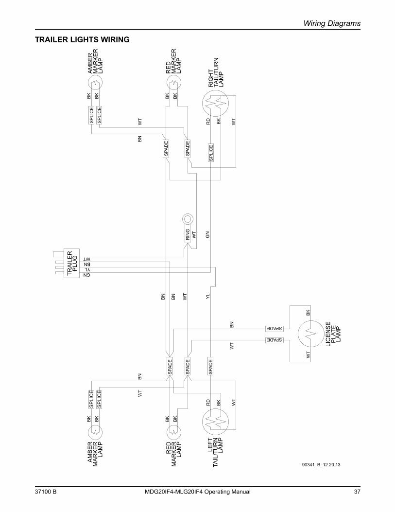
Wiring Diagrams
TRAILER LIGHTS WIRING
GNYLBNWT
MA
RK
ER
LAM
P
AM
BE
R
TRA
ILE
RP
LUG
RIG
HT
TAIL
/TU
RN
LAM
P
LAM
PP
LATE
LIC
EN
SE
MA
RK
ER
LAM
P
RE
D
BK BK
BK BK
RD
WT
BK
SP
LIC
ES
PLI
CE
SPA
DE
SPA
DE
LAM
PTA
IL/T
UR
NLE
FTR
D
WT
BK
SPA
DE
YL
BN
WT
SPADE
SPADE
WT
BK
BN
WT
SP
LIC
EG
N
RIN
G
MA
RK
ER
LAM
P
AM
BE
R
MA
RK
ER
LAM
P
RE
D
BK
BK BK
BK
SP
LIC
E
SP
LIC
E
SPA
DE
SPA
DEB
NW
T
WT
WT
BN
BN
90341_B_12.20.13
37100 B MDG20IF4-MLG20IF4 Operating Manual 37
Wiring Diagrams
This Page Intentionally Left Blank
38 MDG20IF4-MLG20IF4 Operating Manual 37100 B
Section 7 - Options & Accessories
LOWER RADIATOR HOSE HEATER OPTION - USE AND MAINTENANCE
CAUTIONImproper use of the lower radiator hose heater could result in damage to the engine or
personal injury. Do not modify the location of the lower radiator hose heater.
The following points should be followed when operating a unit equipped with a lower radiator hose heater.
• Ensure the cooling system is full of the proper mixture of water and engine coolant before each heater use.
• The heater is designed for all-night operation, however, 2-5 hours of heating just prior to starting is usually sufficient for proper engine starting.
• The unit must be level to maintain proper orientation of the heater while it is in operation.
• Use only an undamaged, outdoor rated, three-prong grounded 120VAC extension cord with a minimum amperage rating of 10A. Connect the cord to a properly grounded 120VAC, GFCI receptacle.
• Before starting the engine, unplug the extension cord from the power first, then unplug the heater cordset from the extension cord.
37100 B MDG20IF4-MLG20IF4 Operating Manual 39
Options & Accessories
This Page Intentionally Left Blank
40 MDG20IF4-MLG20IF4 Operating Manual 37100 B
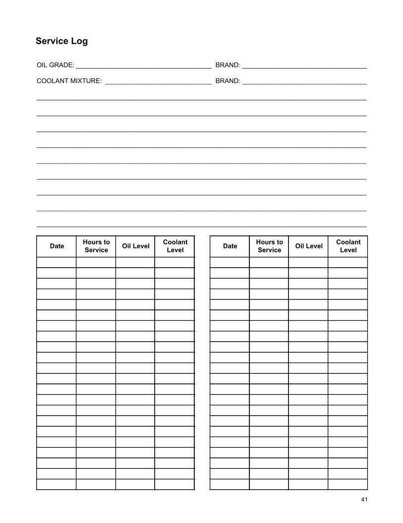
OIL GRADE: _____________________________________ BRAND: __________________________________
COOLANT MIXTURE: _____________________________ BRAND: __________________________________
__________________________________________________________________________________________
__________________________________________________________________________________________
__________________________________________________________________________________________
__________________________________________________________________________________________
__________________________________________________________________________________________
__________________________________________________________________________________________
__________________________________________________________________________________________
__________________________________________________________________________________________
__________________________________________________________________________________________
Date Hours to Service Oil Level Coolant
Level Date Hours toService Oil Level Coolant
Level
Service Log
41

___________________________________________________________________________
___________________________________________________________________________
___________________________________________________________________________
___________________________________________________________________________
___________________________________________________________________________
___________________________________________________________________________
___________________________________________________________________________
___________________________________________________________________________
___________________________________________________________________________
___________________________________________________________________________
___________________________________________________________________________
___________________________________________________________________________
___________________________________________________________________________
___________________________________________________________________________
___________________________________________________________________________
___________________________________________________________________________
___________________________________________________________________________
___________________________________________________________________________
___________________________________________________________________________
___________________________________________________________________________
___________________________________________________________________________
___________________________________________________________________________
___________________________________________________________________________
___________________________________________________________________________
___________________________________________________________________________
___________________________________________________________________________
___________________________________________________________________________
___________________________________________________________________________
Notes
42

___________________________________________________________________________
___________________________________________________________________________
___________________________________________________________________________
___________________________________________________________________________
___________________________________________________________________________
___________________________________________________________________________
___________________________________________________________________________
___________________________________________________________________________
___________________________________________________________________________
___________________________________________________________________________
___________________________________________________________________________
___________________________________________________________________________
___________________________________________________________________________
___________________________________________________________________________
___________________________________________________________________________
___________________________________________________________________________
___________________________________________________________________________
___________________________________________________________________________
___________________________________________________________________________
___________________________________________________________________________
___________________________________________________________________________
___________________________________________________________________________
___________________________________________________________________________
___________________________________________________________________________
___________________________________________________________________________
___________________________________________________________________________
___________________________________________________________________________
___________________________________________________________________________
Notes
43

___________________________________________________________________________
___________________________________________________________________________
___________________________________________________________________________
___________________________________________________________________________
___________________________________________________________________________
___________________________________________________________________________
___________________________________________________________________________
___________________________________________________________________________
___________________________________________________________________________
___________________________________________________________________________
___________________________________________________________________________
___________________________________________________________________________
___________________________________________________________________________
___________________________________________________________________________
___________________________________________________________________________
___________________________________________________________________________
___________________________________________________________________________
___________________________________________________________________________
___________________________________________________________________________
___________________________________________________________________________
___________________________________________________________________________
___________________________________________________________________________
___________________________________________________________________________
___________________________________________________________________________
___________________________________________________________________________
___________________________________________________________________________
___________________________________________________________________________
___________________________________________________________________________
Notes
44