Embed Size (px)
DESCRIPTION
h
Citation preview
1/20Registered Quality System to ISO 9001:2008Form 468sorinc.com
913-888-2630
Series 101/121Differential Pressure Switches
Form 468
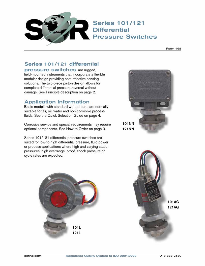
are rugged, field-mounted instruments that incorporate a flexible modular design providing cost effective sensing solutions. The two-piece piston design allows for complete differential pressure reversal without damage. See Principle description on page 2.
Application InformationBasic models with standard wetted parts are normally suitable for air, oil, water and non-corrosive process fluids. See the Quick Selection Guide on page 4.
Corrosive service and special requirements may require optional components. See How to Order on page 3.
Series 101/121 differential pressure switches are suited for low-to-high differential pressure, fluid power or process applications where high and varying static pressures, high overrange, proof, shock pressure or cycle rates are expected.
101NN121NN
Series 101/121 differential pressure switches
101AG121AG
101L121L
Registered Quality System to ISO 9001:2008sorinc.com 913-888-2630
2/20 Registered Quality System to ISO 9001:2008Form 468 sorinc.com
913-888-2630
Fe
atu
res a
nd B
en
efits
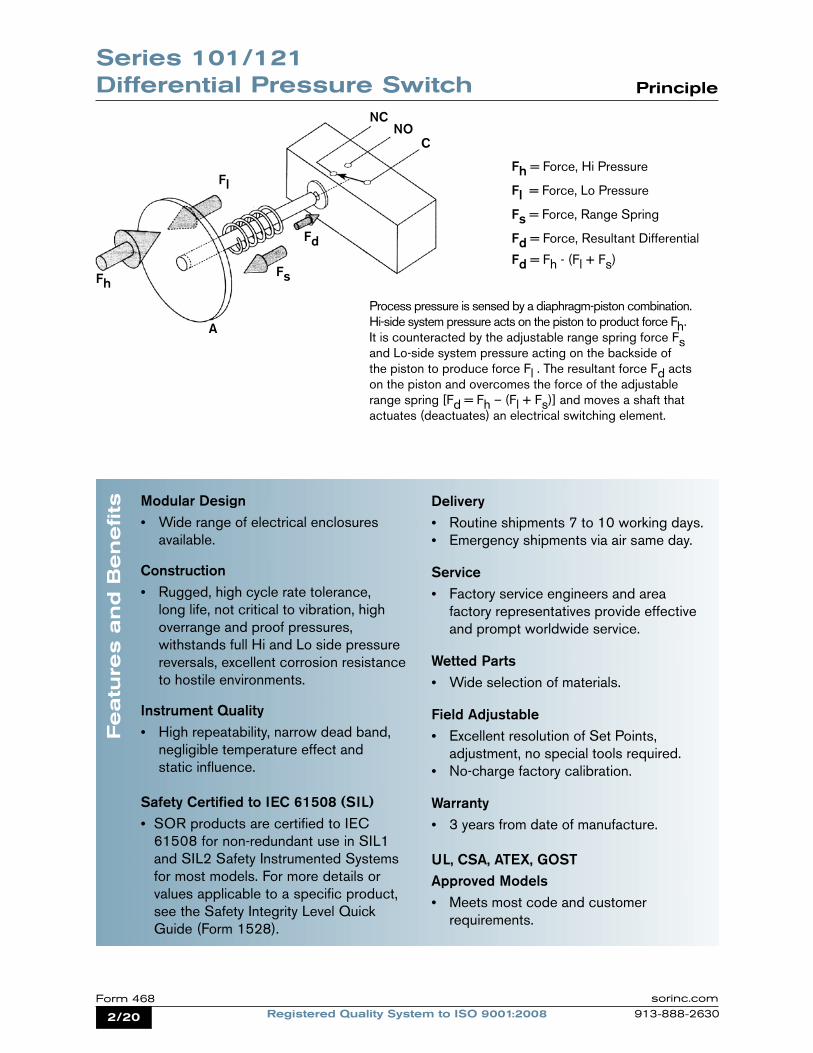
Fh = Force, Hi Pressure
Fl = Force, Lo Pressure
Fs = Force, Range Spring
Fd = Force, Resultant Differential Fd = Fh - (Fl + Fs)
Process pressure is sensed by a diaphragm-piston combination. Hi-side system pressure acts on the piston to product force Fh. It is counteracted by the adjustable range spring force Fs and Lo-side system pressure acting on the backside of the piston to produce force Fl . The resultant force Fd acts on the piston and overcomes the force of the adjustable range spring [Fd = Fh – (Fl + Fs)] and moves a shaft that actuates (deactuates) an electrical switching element.
A
Fh
Fl
Fs
Fd
NCNO
C
Modular Design Wide range of electrical enclosures available.
Construction Rugged, high cycle rate tolerance, long life, not critical to vibration, high overrange and proof pressures, withstands full Hi and Lo side pressure reversals, excellent corrosion resistance to hostile environments.
Instrument Quality High repeatability, narrow dead band, negligible temperature effect and static influence.
Safety Certified to IEC 61508 (SIL) SOR products are certified to IEC 61508 for non-redundant use in SIL1 and SIL2 Safety Instrumented Systems
for most models. For more details or values applicable to a specific product, see the Safety Integrity Level Quick
Guide (Form 1528).
Delivery Routine shipments 7 to 10 working days. Emergency shipments via air same day.
Service Factory service engineers and area factory representatives provide effective and prompt worldwide service.
Wetted Parts Wide selection of materials.
Field Adjustable Excellent resolution of Set Points, adjustment, no special tools required. No-charge factory calibration.
Warranty 3 years from date of manufacture.
UL, CSA, ATEX, GOSTApproved Models Meets most code and customer
requirements.
Series 101/121 Differential Pressure Switch Principle
3/20Registered Quality System to ISO 9001:2008Form 468sorinc.com
913-888-2630
Quick Selection GuideBasic Series 101/121 differential pressure switches with standard wetted parts are normally suitable for air, oil, water and non-corrosive processes. Refer to the Quick Selection Guide section on page 4. Corrosive service and particular customer requirements may require optional components. Refer to the How to Order section on this page or the dedicated page to locate optional components, such as: housings, switching elements, diaphragm systems, pressure ports and accessories. Each position in the model number, except Accessories, must have a designator.
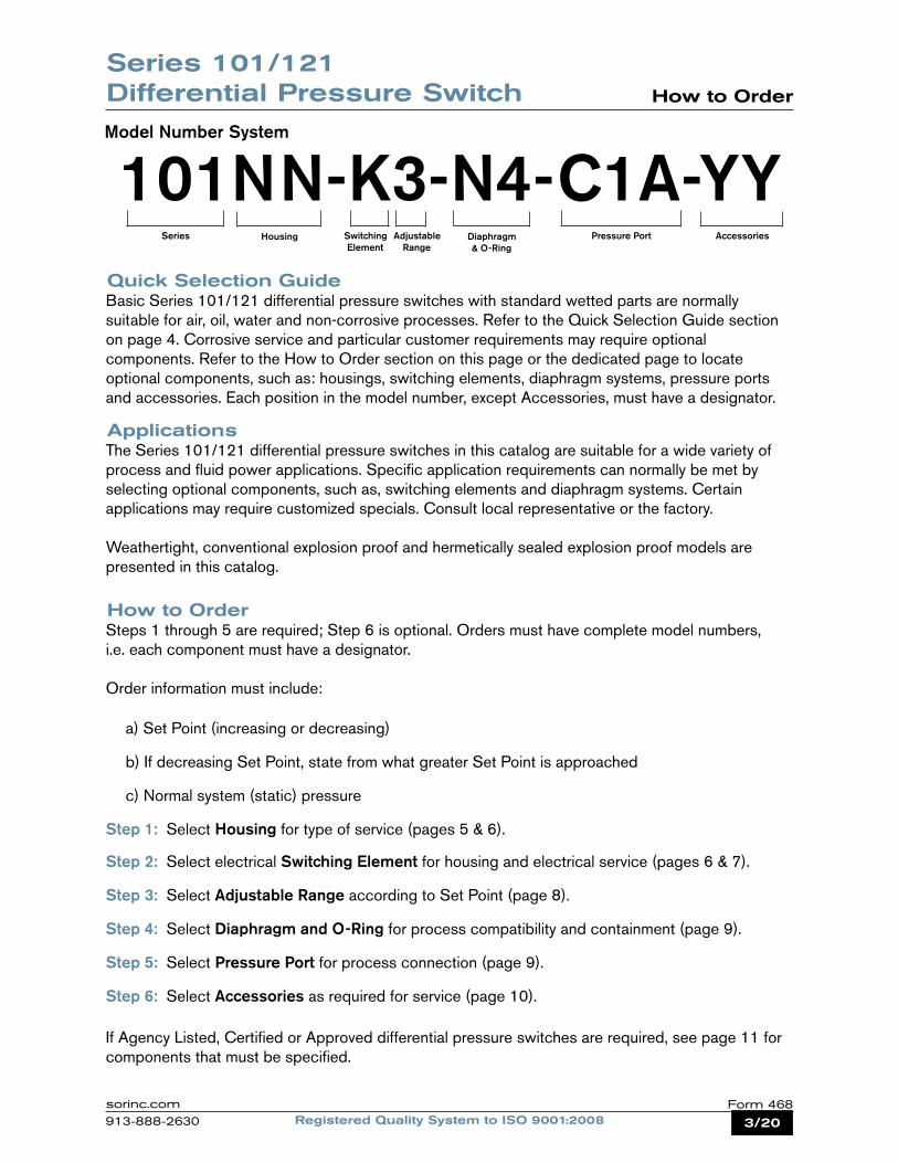
101NN-K3-N4-C1A-YYModel Number System
Series Housing Diaphragm & O-Ring
Switching Element
Adjustable Range
Pressure Port Accessories
ApplicationsThe Series 101/121 differential pressure switches in this catalog are suitable for a wide variety of process and fluid power applications. Specific application requirements can normally be met by selecting optional components, such as, switching elements and diaphragm systems. Certain applications may require customized specials. Consult local representative or the factory.
Weathertight, conventional explosion proof and hermetically sealed explosion proof models are presented in this catalog.
How to OrderSteps 1 through 5 are required; Step 6 is optional. Orders must have complete model numbers, i.e. each component must have a designator.
Order information must include: a) Set Point (increasing or decreasing)
b) If decreasing Set Point, state from what greater Set Point is approached
c) Normal system (static) pressure
Step 1: Select Housing for type of service (pages 5 & 6).
Step 2: Select electrical Switching Element for housing and electrical service (pages 6 & 7).
Step 3: Select Adjustable Range according to Set Point (page 8).
Step 4: Select Diaphragm and O-Ring for process compatibility and containment (page 9).
Step 5: Select Pressure Port for process connection (page 9).
Step 6: Select Accessories as required for service (page 10).
If Agency Listed, Certified or Approved differential pressure switches are required, see page 11 for components that must be specified.
Series 101/121 Differential Pressure Switch How to Order
4/20 Registered Quality System to ISO 9001:2008Form 468 sorinc.com
913-888-2630
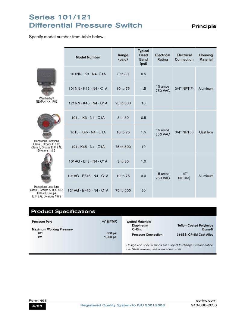
Specify model number from table below.
Weathertight NEMA 4, 4X, IP65
Hazardous Locations Class I, Groups C & D;
Class II, Groups E, F & G; Divisions 1 & 2
Hazardous Locations Class I, Groups A, B, C & D;
Class II, Groups E, F & G; Divisions 1 & 2
Pressure Port 1/4” NPT(F)
Maximum Working Pressure 101 500 psi 121 1,000 psi
Wetted Materials Diaphragm Teflon-Coated Polyimide O-Ring Buna-N
Pressure Connection 316SS; CF-8M Cast Alloy
Product Specifications
Design and specifications are subject to change without notice. For latest revision, see www.sorinc.com.
Model Number Range (psid)
Typical Dead Band (psi)
Electrical Rating
Electrical Connection
Housing Material
101NN - K3 - N4 -C1A 3 to 30 0.5
15 amps250 VAC
3/4” NPT(F) Aluminum101NN - K45 - N4 - C1A 10 to 75 1.5
121NN - K45 - N4 - C1A 75 to 500 10
101L - K3 - N4 - C1A 3 to 30 0.5
15 amps250 VAC
3/4” NPT(F) Cast Iron101L - K45 - N4 - C1A 10 to 75 1.5
121L K45 - N4 - C1A 75 to 500 10
101AG - EF3 - N4 - C1A 3 to 30 1.0
15 amps250 VAC
1/2” NPT(M)
Aluminum101AG - EF45 - N4 - C1A 10 to 75 3.0
121AG - EF45 - N4 - C1A 75 to 500 20
Series 101/121 Differential Pressure Switch Principle
5/20Registered Quality System to ISO 9001:2008Form 468sorinc.com
913-888-2630
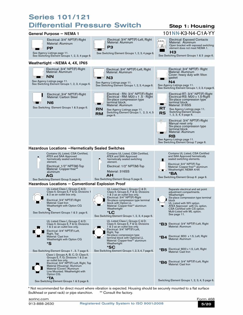
Electrical: 3/4” NPT(F)-Right Material: Aluminum
See Agency Listings page 11.See Switching Element Groups 1, 2, 3, 4 page 6.
Electrical: 3/4” NPT(F)-Right Material: Aluminum NN See Agency Listings page 11.See Switching Element Groups 1, 2, 3, 4 page 6.
Contains UL Listed, CSA Certified, ATEX and SAA Approved hermetically sealed switching element.
Electrical: 1/2” NPT(M)-Top Material: Copper-free** aluminum AGSee Switching Element Group 5 page 6.
Electrical: 3/4” NPT(F)-Left, Right Material: Aluminum
See Switching Element Groups 1, 2, 3, 4 page 6.
Electrical: 3/4” NPT(F)-Left, Right Material: Aluminum N3See Agency Listings page 11.See Switching Element Groups 1, 2, 3, 4 page 6.
Electrical: Exposed Contacts Material: Aluminum Open bracket with exposed switching element does not meet NEMA 1.
See Switching Element Groups 1 & 3 page 6.
Electrical: 3/4” NPT(F)-Right Manual reset only Six-place compression type terminal block Material: Aluminum See Agency Listings page 11.See Switching Element Group 7 page 6.
General Purpose — NEMA 1
Weathertight —NEMA 4, 4X, IP65
Hazardous Locations —Hermetically Sealed Switches
See Agency Listings page 11.Switching Element Groups 1, 2, 3, 4, 5 page 6.
RB
PP
Electrical: 3/4” NPT(F)- Right Material: Aluminum Cover: heavy duty with Viton gasket N4See Agency Listings page 11.See Switching Element Groups 1, 2, 3, 4 page 6.
Electrical: 3/4” NPT(F)-Right Material: Carbon Steel N6See Switching Element Groups 1 & 3 page 6.
Electrical - RN: 3/4” NPT(F)-Right Electrical - RM: M20 x 1 .5 - Right Six-place compression type terminal block. Material: Aluminum See Agency Listings page 11. Switching Element Groups 1, 2, 3, 4, 5 page 6.
RNRM
Electrical-RT: 3/4” NPT(F)-Right Electrical-RS: M20 x 1.5-Right Six-place compression type terminal block Material: 316SS
RTRS
Contains UL Listed, CSA Certified and SAA Approved hermetically sealed switching elements.
Electrical: 3/4” NPT(F)-Top Material: Copper-free** aluminum Weathertight: NEMA 4/4X
*BASee Switching Element Group 6 page 6.
UL Listed Class I, Groups C & D; Class II, Groups E, F & G; Divisions 1 & 2 as an outlet box only.
Electrical: 3/4” NPT(F)-RightMaterial: Cast Iron Weathertight with Option CG
*L
UL Listed Class I, Groups C & D; Class II, Groups E, F & G; Divisions 1 & 2 as an outlet box only.Electrical: 3/4” NPT(F)-RightSix-place compression type terminal block with Option LL Material: Copper-free** aluminum Weathertight
*LC
101NN-K3-N4-C1A-YY
Separate electrical and set point adjustment compartments. Weathertight Six-place compression type terminal block UL Listed with WV option. ATEX Approved with CL option. CSA Certified with CS option.Multi-Listed with ML option. See page 11.
UL Listed Class I, Groups C & D; Class II, Groups E, F & G; Divisions 1 & 2 as an outlet box only.Electrical: 3/4” NPT(F)-Left, Right, TopMaterial: Cast Iron Weathertight with Option CG
*S
UL Listed Class I, Groups C & D; Class II, Groups E, F & G; Divisions 1 & 2 as an outlet box only.Electrical: 3/4” NPT(F)-Left, Right, TopSix-place compression type terminal block with Optional LL Material: Copper-free** aluminum Weathertight
*SC
Class I, Groups A, B, C, D; Class II, Groups E, F, G; Divisions 1 & 2 as an outlet box only. Electrical: 3/4” NPT(F)-Left, Right, Top Material (Housing): Aluminum Material (Cover): Aluminum Line Mounted. Weathertight with Option CG. *TA See Switching Element Groups 1 & 3 page 6.
*B3
*B4
Electrical: 3/4” NPT(F)-Left, Right Material: Aluminum
Electrical: M20 x 1.5, Left, Right Material: Aluminum
*B5
*B6
Electrical: M20 x 1.5, Left, Right Material: Cast Iron
Electrical: 3/4” NPT(F)-Left, Right Material: Cast Iron
Switching Element Groups 1, 2, 3, 4, 5 page 6.
* Not recommended for direct mount where vibration is expected. Housing should be securely mounted to a flat surface (bulkhead or panel rack) or pipe stanchion. ** Consult the factory.
See Switching Element Groups 1 & 3 page 6.See Switching Element Groups 1, 2, 3, 4 page 6.
See Switching Element Groups 1 , 3, 7 page 6. See Switching Element Groups 1, 2, 3, 4, 7 page 6.
Hazardous Locations — Conventional Explosion Proof
P3H3
Contains UL Listed, CSA Certified, ATEX and SAA Approved hermetically sealed switching element.
Electrical: 1/2” NPT(M)-Top
Material: 316SS AH See Switching Element Group 5 page 6.
Series 101/121 Differential Pressure Switch Step 1: Housing
6/20 Registered Quality System to ISO 9001:2008Form 468 sorinc.com
913-888-2630
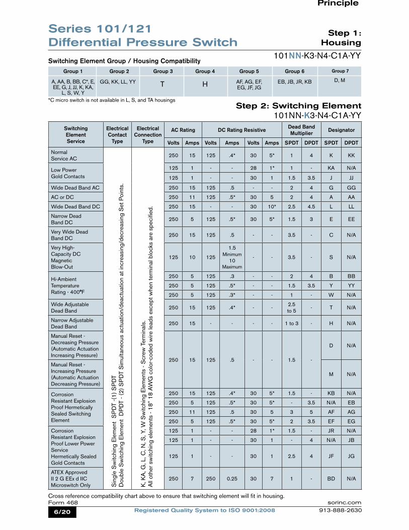
Switching Element Service
Electrical Contact
Type
Electrical Connection
Type
AC Rating DC Rating Resistive Dead Band Multiplier Designator
Volts Amps Volts Amps Volts Amps SPDT DPDT SPDT DPDT
Normal Service AC
250 15 125 .4* 30 5* 1 4 K KK
Low PowerGold Contacts
125 1 - - 28 1* 1 - KA N/A
125 1 - - 30 1 1.5 3.5 J JJ
Wide Dead Band AC 250 15 125 .5 - - 2 4 G GG
AC or DC 250 11 125 .5* 30 5 2 4 A AA
Wide Dead Band DC 250 15 - - 30 10* 2.5 4.5 L LL
Narrow Dead Band DC
250 5 125 .5* 30 5* 1.5 3 E EE
Very Wide Dead Band DC
250 15 125 .5 - - 3.5 - C N/A
Very High-Capacity DCMagnetic Blow-Out
125 10 125
1.5 Minimum
10Maximum
- - 3.5 - S N/A
Hi-Ambient Temperature Rating - 400°F
250 5 125 .3 - - 2 4 B BB
250 5 125 .5* - - 1.5 3.5 Y YY
250 5 125 .3* - - 1 - W N/A
Wide Adjustable Dead Band
250 15 125 .4* - -2.5 to 5
- T N/A
Narrow Adjustable Dead Band
250 15 - - - - 1 to 3 - H N/A
Manual Reset - Decreasing Pressure (Automatic Actuation Increasing Pressure)
250 15 125 .5 - - 1.5 -
D N/A
Manual Reset - Increasing Pressure (Automatic Actuation Decreasing Pressure)
M N/A
Corrosion Resistant Explosion Proof Hermetically Sealed Switching Element
250 15 125 .4* 30 5* 1.5 - KB N/A
250 5 125 .5* 30 5* - 3.5 N/A EB
250 11 125 .5 30 5 3 5 AF AG
250 5 125 .5* 30 5* 2 3.5 EF EG
Corrosion Resistant Explosion Proof Lower Power Service Hermetically Sealed Gold Contacts
125 1 - - 28 1* 1.5 - JR N/A
125 1 - - 30 1 - 4 N/A JB
125 1 - - 30 1 2.5 4 JF JG
ATEX Approved II 2 G EEx d IIC Microswitch Only
250 7 250 0.25 30 7 1 - BD N/A
Switching Element Group / Housing Compatibility
*C micro switch is not available in L, S, and TA housings
Group 2
GG, KK, LL, YY
Group 3
T
Group 4
H
Group 5
AF, AG, EF, EG, JF, JG
Group 6
EB, JB, JR, KB
Group 7
D, M
Group 1
A, AA, B, BB, C*, E, EE, G, J, JJ, K, KA,
L, S, W, Y
Step 2: Switching Element
Step 1:
Housing
101NN-K3-N4-C1A-YY
Cross reference compatibility chart above to ensure that switching element will fit in housing.
Sin
gle
Sw
itchi
ng E
lem
ent
SP
DT
-(1)
SP
DT
Dou
ble
Sw
itchi
ng E
lem
ent
DP
DT
- (2)
SP
DT
Sim
ulta
neou
s ac
tuat
ion/
deac
tuat
ion
at in
crea
sing
/dec
reas
ing
Set
Poi
nts.
K, K
A, G
, L, C
, N, S
, Y, W
Sw
itchi
ng E
lem
ents
- S
crew
Ter
min
als.
All
othe
r sw
itchi
ng e
lem
ents
- 18
” 18
AW
G c
olor
-cod
ed w
ire le
ads
exce
pt w
hen
term
inal
blo
cks
are
spec
ified
.
101NN-K3-N4-C1A-YY
Series 101/121 Differential Pressure Switch
Principle
7/20Registered Quality System to ISO 9001:2008Form 468sorinc.com
913-888-2630
Notes1. AC/DC electrical ratings for switching elements K, KK, KA, J, JJ, G, GG, A, AA, L, LL, E, EE, C, S, B, BB, Y, YY, W, T, H, D and M are UL Recognized and CSA Certified with conditions and exceptions specified in Note 3.2. The hermetically sealed switching element capsule is UL Listed, CSA Certified, ATEX and TestSafe Approved as a snap switch in accordance with the following table with conditions and exceptions specified in Note 3.
3. DC electrical ratings are for resistive loads only. DC ratings marked with an asterisk (*) are not agency recognized or certified but have been verified by testing or experience.
Step 2:
Switching Element
101NN-K3-N4-C1A-YY
4. DPDT switching elements have wire leads except when supplied in housings RN, RT, RM, RS, RB, B3, B4, B5, B6.5. Switching element minimum/maximum ambient temperatures: -40 to 167oF (-40 to 75oC) AF, AG, EB, EF, EG, JB, JF, JG, JR, KB -65 to 400oF (-54 to 204oC) B, Y, W -65 to 250oF (-54 to 120oC) A, E, J -65 to 180oF (-54 to 80oC) All others6. Dead band multipliers must be applied to the typical dead band figures given in the specification tables on page 8.7. Switching elements B, W and Y have an Elgiloy spring. Experience indicates good service in atmospheres with corrosive gases - H2S, ammonia, etc.
Caution: The switching element assembly has been precisely positioned in the housing at the factory for optimum performance. Any inadver-tent movement or replacement in the field will degrade performance, could render the device inoperative and may void the warranty unless factory authorized procedures are followed.
Agency Hazardous Location Conditions Designator
UL ListedCSA Certified
Class I, Groups A, B, C & D; Class II, Groups E, F & G; Divisions 1 & 2
AF, EF, AG, EG, KB, EB, JB, JF,
JG, JR
TestSafe Approved
Ex s Zone 2 IIC T4 IP65Ex tD A22 T105°C IP65
AF, EF, AG, EG, KB, EB
ATEX Approved II 2 G EEx m IIAF, EF, AG, EG, JF, JG
Series 101/121 Differential Pressure Switch
8/20 Registered Quality System to ISO 9001:2008Form 468 sorinc.com
913-888-2630
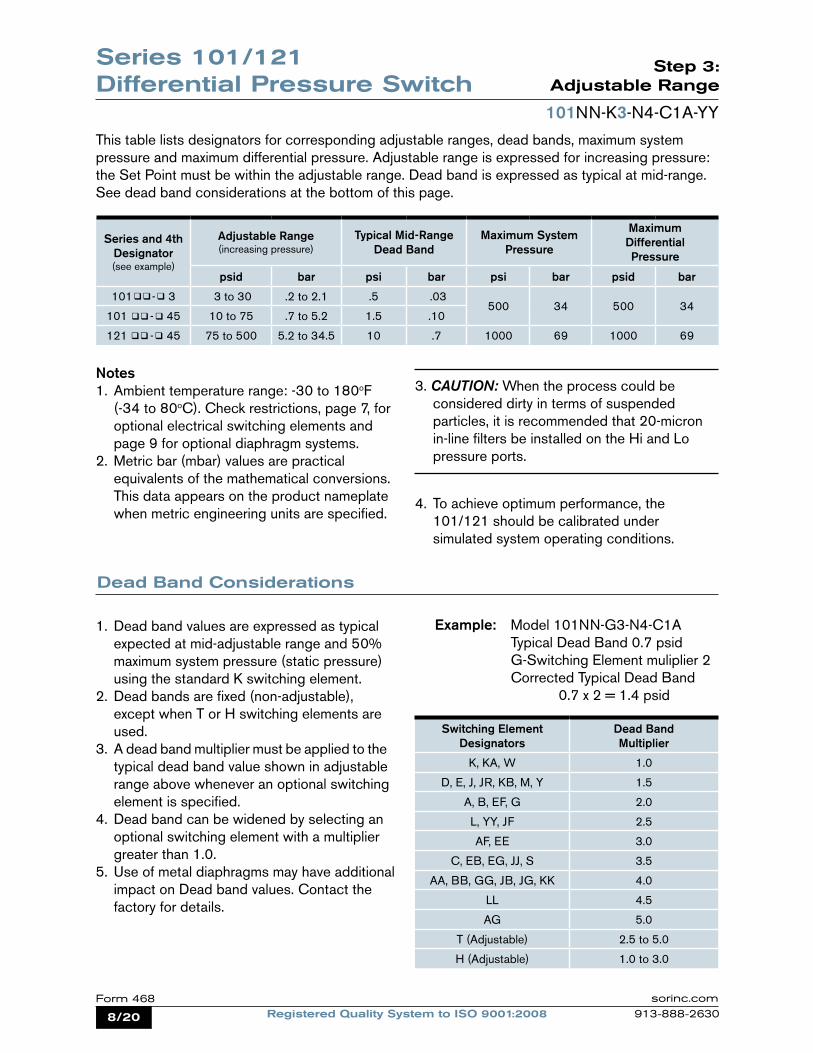
Step 3:
Adjustable Range
101NN-K3-N4-C1A-YY
This table lists designators for corresponding adjustable ranges, dead bands, maximum system pressure and maximum differential pressure. Adjustable range is expressed for increasing pressure: the Set Point must be within the adjustable range. Dead band is expressed as typical at mid-range. See dead band considerations at the bottom of this page.
Notes1. Ambient temperature range: -30 to 180oF (-34 to 80oC). Check restrictions, page 7, for optional electrical switching elements and page 9 for optional diaphragm systems.2. Metric bar (mbar) values are practical equivalents of the mathematical conversions. This data appears on the product nameplate when metric engineering units are specified.
3. Caution: When the process could be considered dirty in terms of suspended particles, it is recommended that 20-micron in-line filters be installed on the Hi and Lo pressure ports.
4. To achieve optimum performance, the 101/121 should be calibrated under simulated system operating conditions.
Dead Band Considerations
1. Dead band values are expressed as typical expected at mid-adjustable range and 50% maximum system pressure (static pressure) using the standard K switching element.2. Dead bands are fixed (non-adjustable), except when T or H switching elements are used.3. A dead band multiplier must be applied to the typical dead band value shown in adjustable range above whenever an optional switching element is specified.4. Dead band can be widened by selecting an optional switching element with a multiplier greater than 1.0.5. Use of metal diaphragms may have additional impact on Dead band values. Contact the factory for details.
Switching Element Designators
Dead Band Multiplier
K, KA, W 1.0
D, E, J, JR, KB, M, Y 1.5
A, B, EF, G 2.0
L, YY, JF 2.5
AF, EE 3.0
C, EB, EG, JJ, S 3.5
AA, BB, GG, JB, JG, KK 4.0
LL 4.5
AG 5.0
T (Adjustable) 2.5 to 5.0
H (Adjustable) 1.0 to 3.0
Series and 4th Designator (see example)
Adjustable Range(increasing pressure)
Typical Mid-Range Dead Band
Maximum System Pressure
Maximum DifferentialPressure
psid bar psi bar psi bar psid bar
101 - 3 3 to 30 .2 to 2.1 .5 .03500 34 500 34
101 - 45 10 to 75 .7 to 5.2 1.5 .10
121 - 45 75 to 500 5.2 to 34.5 10 .7 1000 69 1000 69
Series 101/121 Differential Pressure Switch
Example: Model 101NN-G3-N4-C1A Typical Dead Band 0.7 psid G-Switching Element muliplier 2 Corrected Typical Dead Band 0.7 x 2 = 1.4 psid
9/20Registered Quality System to ISO 9001:2008Form 468sorinc.com
913-888-2630
Step 4:
Diaphragm & O-Ring
101NN-K3-N4-C1A-YY
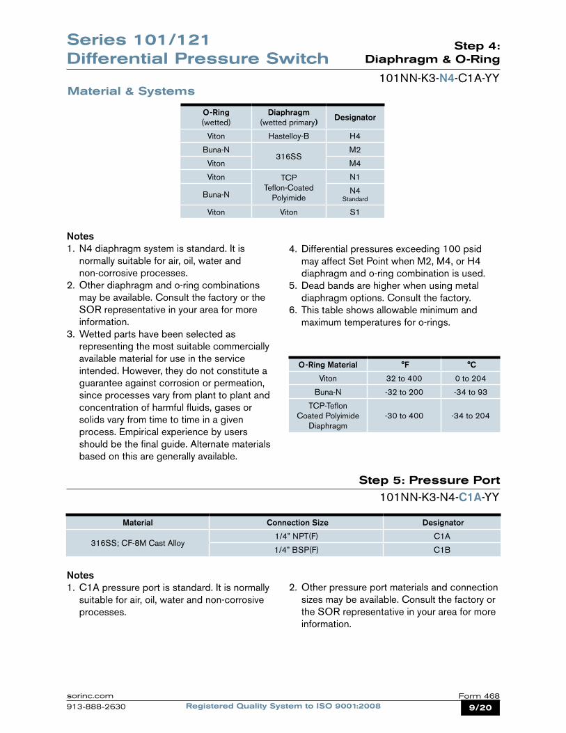
Notes1. N4 diaphragm system is standard. It is normally suitable for air, oil, water and non-corrosive processes.2. Other diaphragm and o-ring combinations may be available. Consult the factory or the SOR representative in your area for more information.3. Wetted parts have been selected as representing the most suitable commercially available material for use in the service intended. However, they do not constitute a guarantee against corrosion or permeation, since processes vary from plant to plant and concentration of harmful fluids, gases or solids vary from time to time in a given process. Empirical experience by users should be the final guide. Alternate materials based on this are generally available.
4. Differential pressures exceeding 100 psid may affect Set Point when M2, M4, or H4 diaphragm and o-ring combination is used.5. Dead bands are higher when using metal diaphragm options. Consult the factory.6. This table shows allowable minimum and maximum temperatures for o-rings.
Step 5: Pressure Port
101NN-K3-N4-C1A-YY
Notes1. C1A pressure port is standard. It is normally suitable for air, oil, water and non-corrosive processes.
2. Other pressure port materials and connection sizes may be available. Consult the factory or the SOR representative in your area for more information.
Material & Systems
O-Ring (wetted)
Diaphragm (wetted primary) Designator
Viton Hastelloy-B H4
Buna-N316SS
M2
Viton M4
Viton TCP Teflon-Coated
Polyimide
N1
Buna-N N4 Standard
Viton Viton S1
O-Ring Material °F °C
Viton 32 to 400 0 to 204
Buna-N -32 to 200 -34 to 93
TCP-Teflon Coated Polyimide
Diaphragm-30 to 400 -34 to 204
Material Connection Size Designator
316SS; CF-8M Cast Alloy1/4” NPT(F) C1A
1/4” BSP(F) C1B
Series 101/121 Differential Pressure Switch
10/20 Registered Quality System to ISO 9001:2008Form 468 sorinc.com
913-888-2630
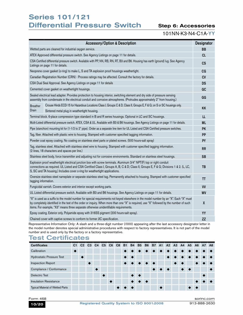
Step 6: Accessories
101NN-K3-N4-C1A-YY
Representative Information Only: A slash and a three-digit number (/000) appearing after the last accessory designator letter in the model number denotes special administrative procedures with respect to factory representatives. It is not part of the model number and is used only by the factory or a factory representative.
Accessory/Option & Description Designator Wetted parts are cleaned for industrial oxygen service. BBATEX Approved differential pressure switch. See Agency Listings on page 11 for details. CLCSA Certified differential pressure switch. Available with PP, NN, RB, RN, RT, B3 and B6. Housing has earth (ground) lug. See Agency Listings on page 11 for details. CS
Neoprene cover gasket (o-ring) to make L, S and TA explosion proof housings weathertight. CGCanadian Registration Number (CRN) - Process ratings may be affected. Consult the factory for details. CVCSA Dual Seal Approval. See Agency Listings on page 11 for details DS
Cemented cover gasket on weathertight housings. GC
Sealed electrical lead adapter. Provides protection to housing interior, switching element and dry side of pressure sensing assembly from condensate in the electrical conduit and corrosive atmospheres. (Protrudes approximately 2” from housing.) GG
Breather Drain
Crouse Hinds ECD-15 for Hazardous Locations Class I, Groups C & D, Class II, Groups E, F & G; on S or SC housings only.KK
Sintered metal plug in weathertight housing.
Terminal block. 6-place compression type standard in B and R series housings. Optional in LC and SC housings. LLMulti-Listed differential pressure switch. ATEX, CSA & UL. Available with B3 & B6 housings. See Agency Listings on page 11 for details. MLPipe (stanchion) mounting kit for (1-1/2 to 2” pipe). Order as a separate line item for UL Listed and CSA Certified pressure switches. PKTag, fiber. Attached with plastic wire to housing. Stamped with customer specified tagging information. PPPowder coat epoxy coating. No coating on stainless steel parts or plated screws. (500 hours-salt spray) PYTag, stainless steel. Attached with stainless steel wire to housing. Stamped with customer specified tagging information. (2 lines, 18 characters and spaces per line.) RR
Stainless steel body, force transmitter and adjusting nut for corrosive environments. Standard on stainless steel housings. SBExplosion proof weathertight electrical junction box with screw terminals. Aluminum 3/4” NPT(F) top or right conduit connections as required. UL Listed and CSA Certified Class I, Groups A, B, C & D; Class II, Groups E, F & G; Divisions 1 & 2. (L, LC, S, SC and TA housing.) Includes cover o-ring for weathertight applications.
TB
Oversize stainless steel nameplate or separate stainless steel tag. Permanently attached to housing. Stamped with customer specified tagging information. TT
Fungicidal varnish. Covers exterior and interior except working parts. VVUL Listed differential pressure switch. Available with B3 and B6 housings. See Agency Listings on page 11 for details. WV“X” is used as a suffix to the model number for special requirements not keyed elsewhere in the model number by an “X”. Each “X” must by completely identified in the text of the order or inquiry. When more than one “X” is required, use “X” followed by the number of such items. For example, “X3” means three separate otherwise unidentifiable requirements.
X
Epoxy coating. Exterior only. Polyamide epoxy with 316SS pigment (200 hours-salt spray). YYChained cover with captive screws to conform to former JIC specification. ZZ
Series 101/121 Differential Pressure Switch
Test CertificatesCertificates C1 C2 C3 C4 C5 C6 C8 B1 B4 B5 B6 B7 A1 A2 A3 A4 A5 A6 A7 A8
Calibration ¿ ¿ ¿ ¿ ¿ ¿ ¿ ¿ ¿ ¿ ¿ ¿ ¿ ¿
Hydrostatic Pressure Test ¿ ¿ ¿ ¿ ¿ ¿ ¿ ¿ ¿ ¿
Inspection Report ¿ ¿ ¿ ¿ ¿ ¿ ¿ ¿ ¿ ¿ ¿
Compliance / Conformance ¿ ¿ ¿ ¿ ¿ ¿ ¿
Dielectric Test ¿ ¿ ¿ ¿
Insulation Resistance ¿ ¿ ¿ ¿ ¿ ¿ ¿
Typical Material of Wetted Parts ¿ ¿ ¿ ¿ ¿ ¿
11/20Registered Quality System to ISO 9001:2008Form 468sorinc.com
913-888-2630
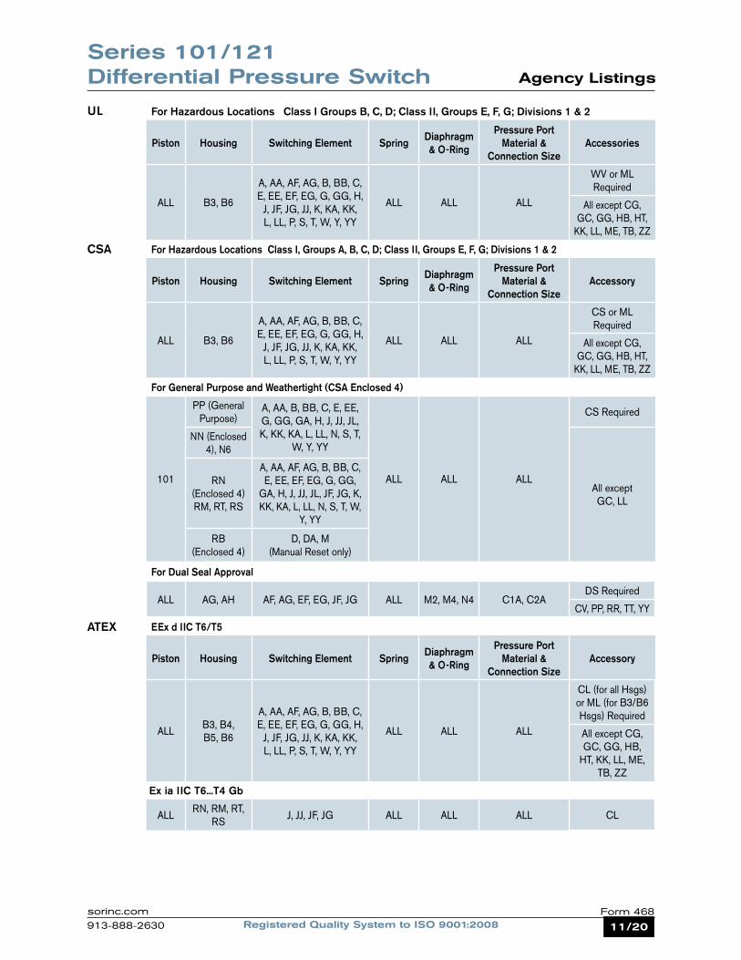
Agency Listings
UL
CSA
ATEX
For Hazardous Locations Class I Groups B, C, D; Class II, Groups E, F, G; Divisions 1 & 2
Piston Housing Switching Element Spring Diaphragm & O-Ring
Pressure Port Material &
Connection SizeAccessories
ALL B3, B6
A, AA, AF, AG, B, BB, C, E, EE, EF, EG, G, GG, H,
J, JF, JG, JJ, K, KA, KK, L, LL, P, S, T, W, Y, YY
ALL ALL ALL
WV or ML Required
All except CG, GC, GG, HB, HT,
KK, LL, ME, TB, ZZ
For Hazardous Locations Class I, Groups A, B, C, D; Class II, Groups E, F, G; Divisions 1 & 2
Piston Housing Switching Element Spring Diaphragm & O-Ring
Pressure Port Material &
Connection SizeAccessory
ALL B3, B6
A, AA, AF, AG, B, BB, C, E, EE, EF, EG, G, GG, H,
J, JF, JG, JJ, K, KA, KK, L, LL, P, S, T, W, Y, YY
ALL ALL ALL
CS or ML Required
All except CG, GC, GG, HB, HT,
KK, LL, ME, TB, ZZ
For General Purpose and Weathertight (CSA Enclosed 4)
101
PP (General Purpose)
A, AA, B, BB, C, E, EE, G, GG, GA, H, J, JJ, JL, K, KK, KA, L, LL, N, S, T,
W, Y, YY
ALL ALL ALL
CS Required
NN (Enclosed 4), N6
All except GC, LL
RN (Enclosed 4)RM, RT, RS
A, AA, AF, AG, B, BB, C, E, EE, EF, EG, G, GG,
GA, H, J, JJ, JL, JF, JG, K, KK, KA, L, LL, N, S, T, W,
Y, YY
RB (Enclosed 4)
D, DA, M (Manual Reset only)
For Dual Seal Approval
ALL AG, AH AF, AG, EF, EG, JF, JG ALL M2, M4, N4 C1A, C2ADS Required
CV, PP, RR, TT, YY
EEx d IIC T6/T5
Piston Housing Switching Element Spring Diaphragm & O-Ring
Pressure Port Material &
Connection SizeAccessory
ALLB3, B4,B5, B6
A, AA, AF, AG, B, BB, C, E, EE, EF, EG, G, GG, H,
J, JF, JG, JJ, K, KA, KK, L, LL, P, S, T, W, Y, YY
ALL ALL ALL
CL (for all Hsgs) or ML (for B3/B6 Hsgs) Required
All except CG, GC, GG, HB,
HT, KK, LL, ME, TB, ZZ
ALLRN, RM, RT,
RSJ, JJ, JF, JG ALL ALL ALL CL
Series 101/121 Differential Pressure Switch
Ex ia IIC T6...T4 Gb
12/20 Registered Quality System to ISO 9001:2008Form 468 sorinc.com
913-888-2630
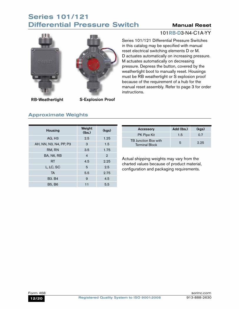
Manual Reset
101RB-D3-N4-C1A-YYSeries 101/121 Differential Pressure Switches in this catalog may be specified with manual reset electrical switching elements D or M. D actuates automatically on increasing pressure. M actuates automatically on decreasing pressure. Depress the button, covered by the weathertight boot to manually reset. Housings must be RB weathertight or S explosion proof because of the requirement of a hub for the manual reset assembly. Refer to page 3 for order instructions.
Approximate Weights
Actual shipping weights may vary from the charted values because of product material, configuration and packaging requirements.
RB-Weathertight S-Explosion Proof
Housing Weight (lbs.) (kgs)
AG, H3 2.5 1.25
AH, NN, N3, N4, PP, P3 3 1.5
RM, RN 3.5 1.75
BA, N6, RB 4 2
RT 4.5 2.25
L, LC, SC 5 2.5
TA 5.5 2.75
B3. B4 9 4.5
B5, B6 11 5.5
Accessory Add (lbs.) (kgs)
PK Pipe Kit 1.5 0.7
TB Junction Box with Terminal Block
5 2.25
Series 101/121 Differential Pressure Switch
13/20Registered Quality System to ISO 9001:2008Form 468sorinc.com
913-888-2630
SOR recognizes that there is no industry convention with respect to terminology and definitions pertinent to pressure switches. This glossary applies to SOR Pressure Switches.
Adjustable Range The span of pressure between upper and lower limits within which the pressure switch may be adjusted to actuate/deactuate. It is expressed for increasing differential pressure.
Dead Band The difference in pressure between the increasing Set Point and the decreasing Set Point. It is expressed as “typical,” which is an average with the increasing Set Point at mid- adjustable range for a pressure switch with the standard K switching element. It is normally fixed (nonadjustable).
Differential Pressure SwitchA bi-stable electromechanical device that actuates/deactuates one or more electrical switching element(s) at a predetermined discrete differential pressure (Set Point) upon rising or falling differential pressure.
DPDT Switching ElementDPDT is two synchronized SPDT switching elements that actuate together at increasing Set Point and deactuate together at decreasing Set Point. Discrete SPDT switching elements allow two independent circuits to be switched; i.e., one AC and one DC.
The synchronization linkage is factory set, and is not field adjustable. Synchronization is verified by connecting test lamps to the switching elements and observing them go“On” simultaneously at actuation and “Off” simultaneously at deactuation
Hermetically Sealed A welded steel capsule with glass-to-metal, factory-sealed, electrical leads that isolates the electrical switching element(s) from the environment.
Maximum Differential PressureThe maximum difference in pressure that may be continuously applied between the Hi and Lo (Lo and Hi) pressure ports without causing permanent change of Set Point, leakage or material failure.
OverrangeThe maximum input pressure that may be continuously applied to the pressure switch without causing permanent change of Set Point, leakage or material failure.
Proof PressureThe maximum input pressure that may be continuously applied to the pressure switch without causing leakage or catastrophic material failure. Permanent change of Set Points may occur, or the device may be rendered inoperative.
RepeatabilityThe ability of a pressure switch to successively operate at a Set Point that is approached from a starting point in the same direction and returns to the starting point over three consecutive cycles to establish a pressure profile. The closeness of the measured Set Point values is normally expressed as a percentage of full scale (maximum adjustable range pressure).
Set PointThat discrete pressure at which the pressure switch is adjusted to actuate/deactuate on rising or falling pressure. It must fall within the adjustable range and be called out as increasing or decreasing differential pressure.
SPDT Switching Element Single-Pole, Double Throw (SPDT) has three connections: C — Common, NO — Normally Open and NC — Normally Closed, which allows the switching element to be electrically connected to the circuit in either NO or NC state.
Glossary of Terms
Series 101/121 Differential Pressure Switch
14/20 Registered Quality System to ISO 9001:2008Form 468 sorinc.com
913-888-2630
ISO-9001
14685 W 105TH ST LENEXA, KS 66215 USA913-888-2630SORINC.COM
ATYP
7.10.28
40.51.59
26.11.03
28.61.13
** 56.52.22
60.32.38
28.61.13
61.92.44
154.16.07
38.11.50
108.14.25
69.92.75
52.42.06
33.31.31
PROCESSCONNECTION SIZE LENGTH A
1/4 NPTMSHOWN
29.71.17
1/2 NPTF 37.61.48
1/2 NPTM 34.81.37
3/4 NPTF 39.91.57
HOUSINGGROUP ** DIMENSION
NN & N3 SHOWN
N4 4.6ADD 0.18
PP & P3 1.5SUBTRACT 0.06
Model Name: 0090602.ASSEM/2/2
PRODUCT CERTIFICATION DRAWINGALL DIMENSIONS ARE ±1/16 INUNLESS OTHERWISE SPECIFIED
MMLINEAR = IN
DRAWN BY
K MITCHELLCHECKED BY
J REHMENGINEER APPROVAL
J MODIGDATE
10 OCT 2011THIS DRAWING IS THE EXCLUSIVE PROPERTY OF SOR.
NO USE WHATSOEVER OF THE INFORMATION CONTAINEDHEREON, NOR REPRODUCTION IN WHOLE OR PART MAY BE
MADE WITHOUT THE EXPRESS WRITTEN PERMISSION OF SOR.
TITLE
DIMENSION DRAWING 101/121NN, N3, N4, PP & P3
EO NUMBER: 5123
SCALE: 1.00
DO NOT SCALE PRINT
DRAWING NUMBER REV
0090602 3
SHEET 1 OF 1DWG SIZE
B
MODEL # SALES ORDER # LINE ITEM # PURCHASE ORDER #SALES PAGE
CLEARANCE SLOTS
FOR 6.40.25 HARDWARE WITH
63.52.50 MIN TO 76.2
3.00 MAX
MOUNTING CENTERS
1/4 NPTF HI SIDEPROCESS CONNECTION
1/4 NPTF LO SIDEPROCESS CONNECTION
ELECTRICALCONNECTION3/4 NPTF STD1/2 NPTF OPT
(BOTH SIDES ONN3 & P3 HSGS)
1
Reset Form
Series 101/121 Differential Pressure Switch Dimensions
Dimensions in this catalog are for reference only. They may be changed without notice. Contact the factory for certified drawings for a particular model number. Dimensions are expressed as millimeters over inches (Linear = mm/in.)
Housing: N6
Weathertight - Nonhazardous Service (NEMA 4, 4X IP65)
Housing: NN, N3, N4
Drawing 0090603
Drawing 0090602
15/20Registered Quality System to ISO 9001:2008Form 468sorinc.com
913-888-2630
ISO-9001
14685 W 105TH ST LENEXA, KS 66215 USA913-888-2630SORINC.COM
28.61.12
26.21.03
65.62.58
7.10.28
28.61.13
61.92.44
179.17.05
29.71.17TYP
38.11.50
52.02.05
107.34.22
33.31.31
69.92.75
CLEARANCE SLOTS
FOR 6.40.25 HARDWARE
WITH 63.52.50 MIN TO 76.2
3.00 MAX
MOUNTING CENTERS
ELECTRICALCONNECTION
SEE CHART
40.51.59
Model Name: 0090605.ASSEM/3/3+
PRODUCT CERTIFICATION DRAWINGALL DIMENSIONS ARE ±1/16 INUNLESS OTHERWISE SPECIFIED
MMLINEAR = IN
DRAWN BY
K MITCHELLCHECKED BY
M SMITHENGINEER APPROVAL
S BOALDATE
17 OCT 2011THIS DRAWING IS THE EXCLUSIVE PROPERTY OF SOR.
NO USE WHATSOEVER OF THE INFORMATION CONTAINEDHEREON, NOR REPRODUCTION IN WHOLE OR PART MAY BE
MADE WITHOUT THE EXPRESS WRITTEN PERMISSION OF SOR.
TITLE
DIMENSION DRAWING 101/121 R-SERIES HOUSING
EO NUMBER: 5123
SCALE: 0.85
DO NOT SCALE PRINT
DRAWING NUMBER REV
0090605 4
SHEET 1 OF 1DWG SIZE
B
MODEL # SALES ORDER # LINE ITEM # PURCHASE ORDER #SALES PAGE
HOUSING ELECTRICALCONNECTION
RL3/4 NPTF STD1/2 NPTF OPT
LH & RH
RM M20 X 1.5 FRH ONLY
RN3/4 NPTF STD1/2 NPTF OPT
RH ONLY
RS M20 X 1.5 FRH ONLY
RT3/4 NPTF STD1/2 NPTF OPT
RH ONLY
RU3/4 NPTF STD1/2 NPTF OPT
LH & RH
RW M20 X 1.5 FLH & RH
RY M20 X 1.5 FLH & RH
1/4 NPTMPROCESSCONNECTIONOPTIONAL
1/4 NPTFHI SIDE
PROCESSCONNECTION
1/4 NPTFLO SIDEPROCESSCONNECTION
1
Reset Form
Series 101/121Differential Pressure Switch Dimensions
Dimensions in this catalog are for reference only. They may be changed without notice. Contact the factory for certified drawings for a particular model number. Dimensions are expressed as millimeters over inches (Linear = mm/in.)
Housing: RB Manual Reset
Housing: RM, RN, RS, RT
Weathertight - Non-hazardous Service (NEMA 4, 4X IP65)
Drawing 0090604
Drawing 0090605
16/20 Registered Quality System to ISO 9001:2008Form 468 sorinc.com
913-888-2630
ISO-9001
14685 W 105TH ST LENEXA, KS 66215 USA913-888-2630SORINC.COM
ATYP
7.10.28
40.51.59
26.11.03
28.61.13
** 56.52.22
60.32.38
28.61.13
61.92.44
154.16.07
38.11.50
108.14.25
69.92.75
52.42.06
33.31.31
PROCESSCONNECTION SIZE LENGTH A
1/4 NPTMSHOWN
29.71.17
1/2 NPTF 37.61.48
1/2 NPTM 34.81.37
3/4 NPTF 39.91.57
HOUSINGGROUP ** DIMENSION
NN & N3 SHOWN
N4 4.6ADD 0.18
PP & P3 1.5SUBTRACT 0.06
Model Name: 0090602.ASSEM/2/2
PRODUCT CERTIFICATION DRAWINGALL DIMENSIONS ARE ±1/16 INUNLESS OTHERWISE SPECIFIED
MMLINEAR = IN
DRAWN BY
K MITCHELLCHECKED BY
J REHMENGINEER APPROVAL
J MODIGDATE
10 OCT 2011THIS DRAWING IS THE EXCLUSIVE PROPERTY OF SOR.
NO USE WHATSOEVER OF THE INFORMATION CONTAINEDHEREON, NOR REPRODUCTION IN WHOLE OR PART MAY BE
MADE WITHOUT THE EXPRESS WRITTEN PERMISSION OF SOR.
TITLE
DIMENSION DRAWING 101/121NN, N3, N4, PP & P3
EO NUMBER: 5123
SCALE: 1.00
DO NOT SCALE PRINT
DRAWING NUMBER REV
0090602 3
SHEET 1 OF 1DWG SIZE
B
MODEL # SALES ORDER # LINE ITEM # PURCHASE ORDER #SALES PAGE
CLEARANCE SLOTS
FOR 6.40.25 HARDWARE WITH
63.52.50 MIN TO 76.2
3.00 MAX
MOUNTING CENTERS
1/4 NPTF HI SIDEPROCESS CONNECTION
1/4 NPTF LO SIDEPROCESS CONNECTION
ELECTRICALCONNECTION3/4 NPTF STD1/2 NPTF OPT
(BOTH SIDES ONN3 & P3 HSGS)
1
Reset Form
Series 101/121 Differential Pressure Switch Dimensions
Dimensions in this catalog are for reference only. They may be changed without notice. Contact the factory for certified drawings for a particular model number. Dimensions are expressed as millimeters over inches (Linear = mm/in.)
Housing: H3 Open Bracket
General Purpose - Non-hazardous Service
Housing: PP, P3 NEMA 1
Drawing 0090601
Drawing 0090602
17/20Registered Quality System to ISO 9001:2008Form 468sorinc.com
913-888-2630
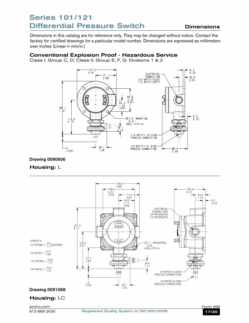
Series 101/121 Differential Pressure Switch Dimensions
Dimensions in this catalog are for reference only. They may be changed without notice. Contact the factory for certified drawings for a particular model number. Dimensions are expressed as millimeters over inches (Linear = mm/in.)
Housing: L
Housing: LC
Conventional Explosion Proof - Hazardous ServiceClass I, Group C, D; Class II, Group E, F, G: Divisions 1 & 2
Drawing 0090606
Drawing 0091068
ISO-9001
14685 W 105TH ST LENEXA, KS 66215 USA913-888-2630SORINC.COM
149.55.88
71.42.81
8.70.34
34.01.34
106.44.19
108.04.25(TYP)
54.02.13(TYP)
72.32.85
126.24.97
207.48.17
A(TYP) 38.1
1.50
28.61.13
MOUNTING
HOLE (TYP 4)
7.10.28
ELECTRICALCONNECTION
3/4 NPT(F)(STD)1/2 NPT(F)(OPT)
Model Name: 0091068.ASSEM/3/0+
PRODUCT CERTIFICATION DRAWINGALL DIMENSIONS ARE ±1/16 INUNLESS OTHERWISE SPECIFIED
MMLINEAR = IN
DRAWN BY
M SMITHCHECKED BY
J REHMENGINEER APPROVAL
S BOALDATE
3/10/11THIS DRAWING IS THE EXCLUSIVE PROPERTY OF SOR.
NO USE WHATSOEVER OF THE INFORMATION CONTAINEDHEREON, NOR REPRODUCTION IN WHOLE OR PART MAY BE
MADE WITHOUT THE EXPRESS WRITTEN PERMISSION OF SOR.
TITLE
DIM DWG 101/121 LC
EO NUMBER: 5090
SCALE: 0.50
DO NOT SCALE PRINT
DRAWING NUMBER REV
0091068 3
SHEET 1 OF 1DWG SIZE
B
MODEL # SALES ORDER # LINE ITEM # PURCHASE ORDER #
LENGTH A29.71/4 NPT(M) = (SHOWN)1.17
37.61/2 NPT(F) = 1.48
34.8 1/2 NPT(M) = 1.37
39.9 3/4 NPT(F) = 1.57
1/4 NPT(F) HI SIDEPROCESS CONNECTION
1/4 NPT(F) LO SIDEPROCESS CONNECTION
Reset Form
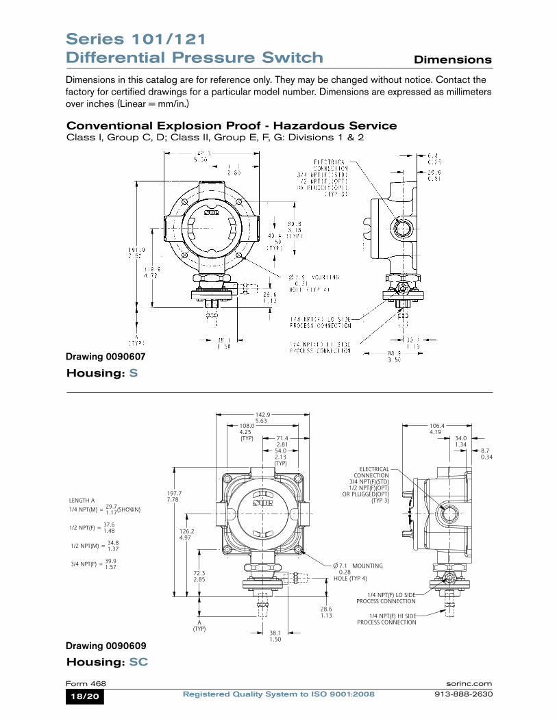
18/20 Registered Quality System to ISO 9001:2008Form 468 sorinc.com
913-888-2630
Housing: S
Housing: SC
Series 101/121 Differential Pressure Switch Dimensions
Dimensions in this catalog are for reference only. They may be changed without notice. Contact the factory for certified drawings for a particular model number. Dimensions are expressed as millimeters over inches (Linear = mm/in.)
Conventional Explosion Proof - Hazardous ServiceClass I, Group C, D; Class II, Group E, F, G: Divisions 1 & 2
Drawing 0090607
Drawing 0090609
ISO-9001
14685 W 105TH ST LENEXA, KS 66215 USA913-888-2630SORINC.COM
54.02.13(TYP)
142.95.63
71.42.81
8.70.34
34.01.34
106.44.19
28.61.13
38.11.50
A(TYP)
72.32.85
126.24.97
197.77.78
108.04.25(TYP)
MOUNTING
HOLE (TYP 4)
7.10.28
ELECTRICALCONNECTION
3/4 NPT(F)(STD)1/2 NPT(F)(OPT)
OR PLUGGED(OPT)(TYP 3)
Model Name: 0090609.ASSEM/3/0+
PRODUCT CERTIFICATION DRAWINGALL DIMENSIONS ARE ±1/16 INUNLESS OTHERWISE SPECIFIED
MMLINEAR = IN
DRAWN BY
M SMITHCHECKED BY
J REHMENGINEER APPROVAL
S BOALDATE
3/10/11THIS DRAWING IS THE EXCLUSIVE PROPERTY OF SOR.
NO USE WHATSOEVER OF THE INFORMATION CONTAINEDHEREON, NOR REPRODUCTION IN WHOLE OR PART MAY BE
MADE WITHOUT THE EXPRESS WRITTEN PERMISSION OF SOR.
TITLE
DIM DWG 101/121 SC
EO NUMBER: 5090
SCALE: 0.50
DO NOT SCALE PRINT
DRAWING NUMBER REV
0090609 3
SHEET 1 OF 1DWG SIZE
B
MODEL # SALES ORDER # LINE ITEM # PURCHASE ORDER #
LENGTH A29.71/4 NPT(M) = (SHOWN)1.17
37.61/2 NPT(F) = 1.48
34.8 1/2 NPT(M) = 1.37
39.9 3/4 NPT(F) = 1.57
1/4 NPT(F) HI SIDEPROCESS CONNECTION
1/4 NPT(F) LO SIDEPROCESS CONNECTION
Reset Form
19/20Registered Quality System to ISO 9001:2008Form 468sorinc.com
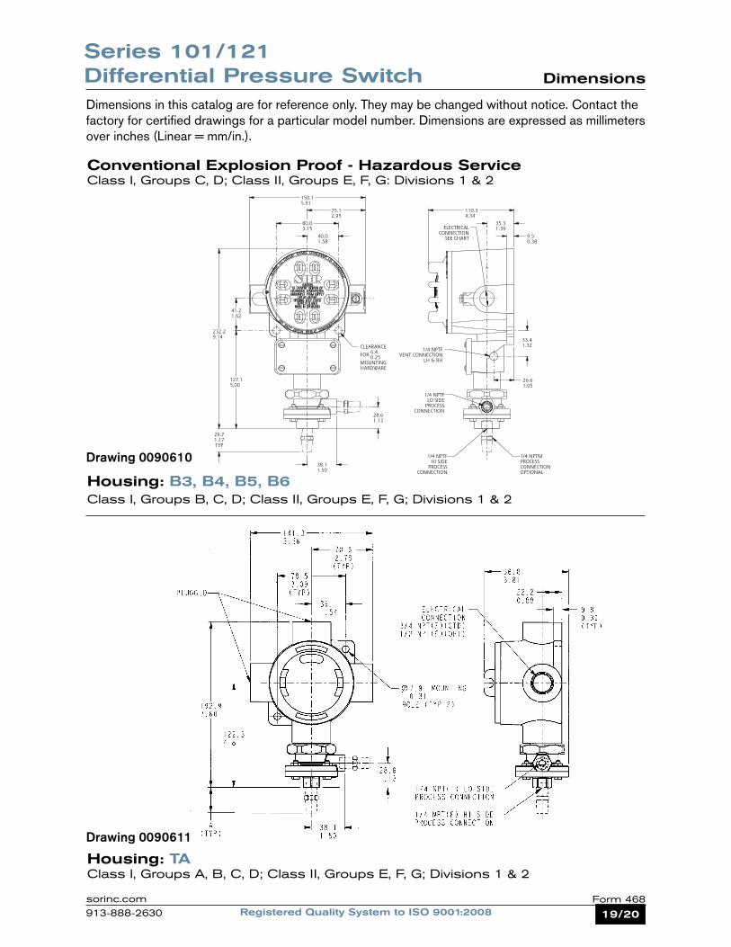
913-888-2630
Conventional Explosion Proof - Hazardous ServiceClass I, Groups C, D; Class II, Groups E, F, G: Divisions 1 & 2
Housing: B3, B4, B5, B6Class I, Groups B, C, D; Class II, Groups E, F, G; Divisions 1 & 2
Housing: TAClass I, Groups A, B, C, D; Class II, Groups E, F, G; Divisions 1 & 2
Series 101/121 Differential Pressure Switch Dimensions
Dimensions in this catalog are for reference only. They may be changed without notice. Contact the factory for certified drawings for a particular model number. Dimensions are expressed as millimeters over inches (Linear = mm/in.).
Drawing 0090610
ISO-9001
14685 W 105TH ST LENEXA, KS 66215 USA913-888-2630SORINC.COM
127.15.00
232.29.14
29.71.17TYP
9.50.38
35.31.39
110.34.34
26.61.05
33.41.32
28.61.13
38.11.50
41.21.62
40.01.58
80.03.15
75.12.95
150.15.91
CLEARANCE
FOR 6.40.25
MOUNTINGHARDWARE
1/4 NPTFVENT CONNECTION
LH & RH
ELECTRICALCONNECTION
SEE CHART
Model Name: 0090610.ASSEM/5/0+
PRODUCT CERTIFICATION DRAWINGALL DIMENSIONS ARE ±1/16 INUNLESS OTHERWISE SPECIFIED
MMLINEAR = IN
DRAWN BY
K MITCHELLCHECKED BY
M SMITHENGINEER APPROVAL
S BOALDATE
24 JUN 2011THIS DRAWING IS THE EXCLUSIVE PROPERTY OF SOR.
NO USE WHATSOEVER OF THE INFORMATION CONTAINEDHEREON, NOR REPRODUCTION IN WHOLE OR PART MAY BE
MADE WITHOUT THE EXPRESS WRITTEN PERMISSION OF SOR.
TITLE
DIMENSION DRAWING101/121 B & J
EO NUMBER: 4441
SCALE: 0.69
DO NOT SCALE PRINT
DRAWING NUMBER REV
0090610 5
SHEET 1 OF 1DWG SIZE
B
MODEL # SALES ORDER # LINE ITEM # PURCHASE ORDER #SALES PAGE
HOUSING ELECTRICALCONNECTION
B3 & B63/4 NPTF STD1/2 NPTF OPT
LH & RH
B4 & B5 M20 X 1.5 FLH & RH
J4 3/4 PFFRH ONLY
1/4 NPTFHI SIDE
PROCESSCONNECTION
1/4 NPTFLO SIDE
PROCESSCONNECTION
1/4 NPTMPROCESSCONNECTIONOPTIONAL
1
Reset Form
Drawing 0090611
20/20 Registered Quality System to ISO 9001:2008Form 468 sorinc.com
913-888-2630
ISO-9001
14685 W 105TH ST LENEXA, KS 66215 USA913-888-2630SORINC.COM
7.10.28
37.41.47
54.72.15
84.93.34
38.11.50
28.61.13
60.52.38
121.04.77
54.02.13
108.04.25
82.33.24
215.98.50
ATYP
Model Name: 0090612.ASSEM/4/2
PRODUCT CERTIFICATION DRAWINGALL DIMENSIONS ARE ±1/16 INUNLESS OTHERWISE SPECIFIED
MMLINEAR = IN
DRAWN BY
K MITCHELLCHECKED BY
M SMITHENGINEER APPROVAL
S BOALDATE
14 SEP 2011THIS DRAWING IS THE EXCLUSIVE PROPERTY OF SOR.
NO USE WHATSOEVER OF THE INFORMATION CONTAINEDHEREON, NOR REPRODUCTION IN WHOLE OR PART MAY BE
MADE WITHOUT THE EXPRESS WRITTEN PERMISSION OF SOR.
TITLE
DIMENSION DRAWING101/121 BA
EO NUMBER: 5095
SCALE: 0.70
DO NOT SCALE PRINT
DRAWING NUMBER REV
0090612 5
SHEET 1 OF 1DWG SIZE
B
MODEL # SALES ORDER # LINE ITEM # PURCHASE ORDER #SALES PAGE
PROCESSCONN SIZE LENGTH A
1/4 NPTMSHOWN
29.71.17
1/2 NPTF 37.61.48
1/2 NPTM 34.81.37
3/4 NPTF 39.91.57
41.6ADD FOR M20 X 1.5 F1.64ELECTRICAL CONNECTION
CLEARANCE
FOR 6.40.25
MOUNTINGHARDWARE
1/4 OR 1/2 NPTMPROCESS CONNECTIONOPTIONAL
ELECTRICALCONNECTION3/4 NPTF STD1/2 NPTF OPT
M20 X 1.5 F OPT
FACTORY SEALED LEADSCOLOR CODED AND MARKED
457.218.00 MINIMUM LENGTH
1/4 NPTF HI SIDEPROCESS CONNECTION
1/4 NPTF LO SIDEPROCESS CONNECTION
1
1
1
Reset Form
14685 West 105th Street, Lenexa, Kansas 66215 913-888-2630 Toll Free 800-676-6794 sorinc.com
Form 468 (07.12) ©2012 SOR Inc.
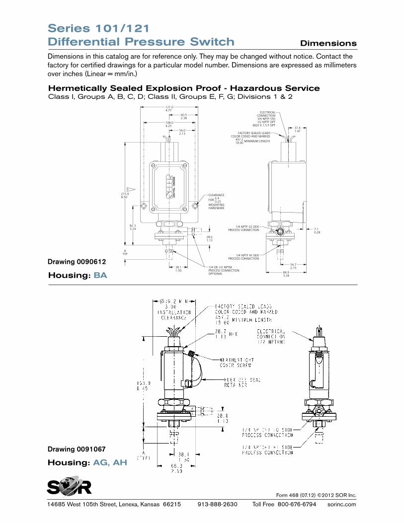
Hermetically Sealed Explosion Proof - Hazardous ServiceClass I, Groups A, B, C, D; Class II, Groups E, F, G; Divisions 1 & 2
Housing: BA
Housing: AG, AH
Series 101/121 Differential Pressure Switch Dimensions
Dimensions in this catalog are for reference only. They may be changed without notice. Contact the factory for certified drawings for a particular model number. Dimensions are expressed as millimeters over inches (Linear = mm/in.)
Drawing 0090612
Drawing 0091067
1/16Registered Quality System to ISO 9001:2008Form 281sorinc.com
913-888-2630
Adjustable Dead Band Pressure Switches
Form 281
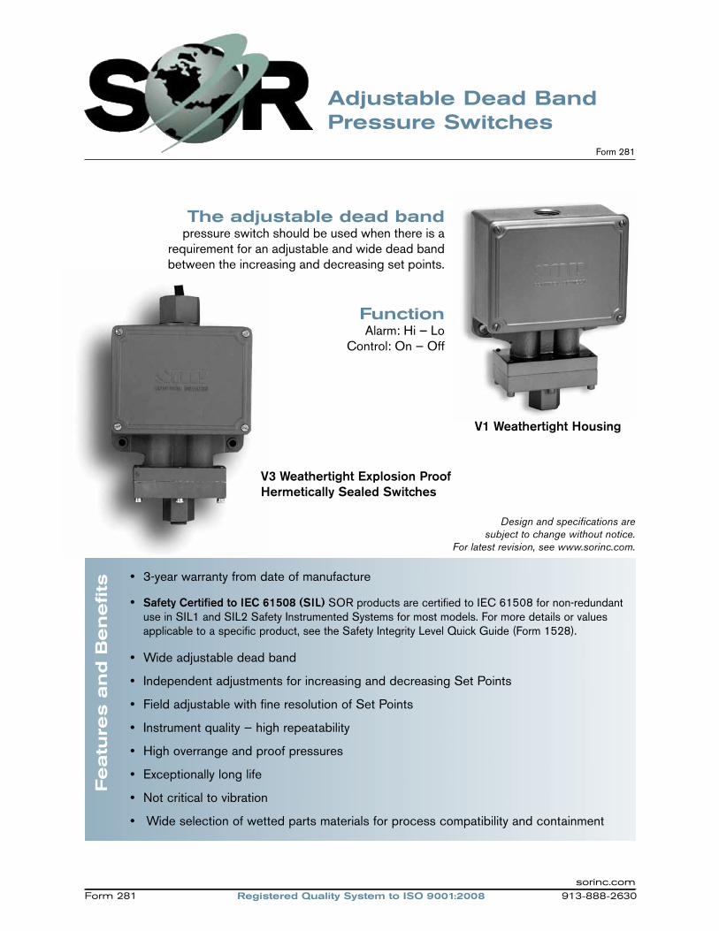
The adjustable dead bandpressure switch should be used when there is a
requirement for an adjustable and wide dead band between the increasing and decreasing set points.
FunctionAlarm: Hi — Lo
Control: On — Off
V1 Weathertight Housing
Featu
res a
nd B
en
efits
• 3-year warranty from date of manufacture
• Safety Certified to IEC 61508 (SIL) SOR products are certified to IEC 61508 for non-redundant use in SIL1 and SIL2 Safety Instrumented Systems for most models. For more details or values applicable to a specific product, see the Safety Integrity Level Quick Guide (Form 1528).
• Wide adjustable dead band
• Independent adjustments for increasing and decreasing Set Points
• Field adjustable with fine resolution of Set Points
• Instrument quality — high repeatability
• High overrange and proof pressures
• Exceptionally long life
• Not critical to vibration
• Wide selection of wetted parts materials for process compatibility and containment
Design and specifications are subject to change without notice.
For latest revision, see www.sorinc.com.
V3 Weathertight Explosion Proof Hermetically Sealed Switches
Registered Quality System to ISO 9001:2008 913-888-2630Form 281sorinc.com
2/16 Registered Quality System to ISO 9001:2008Form 281 sorinc.com
913-888-2630
The SOR Adjustable Dead Band pressure switch incorporates two industry proven Static “O” Ring pressure sensing elements. Media pressure on the areas of the pistons counteracts the forces of the range springs — each adjustable by a separate adjusting nut — and moves the piston shafts to operate the lever assembly which, in turn, actuates and deactuates the electrical switching element. Each pressure sensing element of the Adjustable Dead Band pressure switch is a force balance piston-actuated assembly sealed by a flexible diaphragm and an o-ring that is static. The only wetted parts are the single pressure port, two diaphragms, and two o-rings all indicated with asterisks (*) in this illustration.
Principle
Adjustable Dead Band Pressure Switches
No Pressure: Electrical switching element is deactuated.
Pressure greater than decreasing Set Point but less than increasing Set Point. Electrical switching element remains deactuacted.
Pressure equal to or greater than increasing Set Point: Electrical switching element is actuated.
Pressure less than increasing Set Point but greater than decreasing Set Point: Electrical switching element remains actuated.
Pressure equal to or less than decreasing Set Point: Electrical switching element is deactuated.
*Pressure Port
Principle SchematicThe lever assembly travel illustrated here has been exaggerated for clarity.
Screw Terminal Block (Weathertight Model Only)
Lever Assembly
Calibration Scale
Decreasing Set Point Adjusting Nut
Piston Assembly
Pressure Range Spring
*Diaphragm
*O-Ring
*O-Ring
*Diaphragm
Pressure Range Spring
Piston Assembly
Housing
Increasing Set PointAdjusting Nut
Calibration Scale
Electrical Switching Element (Explosion Proof
Model has Hermetically Sealed Switching Element
Capsule)
Actuation Deactuation
3/16Registered Quality System to ISO 9001:2008Form 281sorinc.com
913-888-2630
How to Order
Adjustable Dead Band Pressure Switches
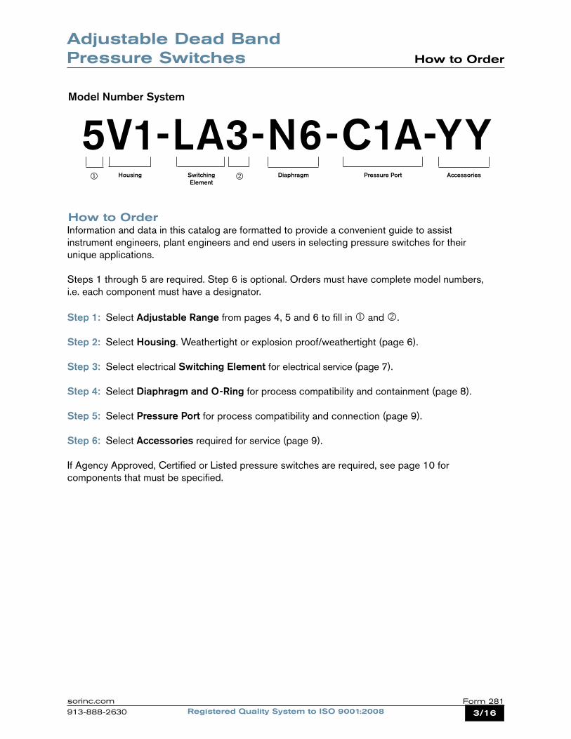
5V1-LA3-N6-C1A-YYModel Number System
Housing DiaphragmSwitching Element
Pressure Port Accessories
How to OrderInformation and data in this catalog are formatted to provide a convenient guide to assist instrument engineers, plant engineers and end users in selecting pressure switches for their unique applications.
Steps 1 through 5 are required. Step 6 is optional. Orders must have complete model numbers, i.e. each component must have a designator.
Step 1: Select Adjustable Range from pages 4, 5 and 6 to fill in and .
Step 2: Select Housing. Weathertight or explosion proof/weathertight (page 6).
Step 3: Select electrical Switching Element for electrical service (page 7).
Step 4: Select Diaphragm and O-Ring for process compatibility and containment (page 8).
Step 5: Select Pressure Port for process compatibility and connection (page 9).
Step 6: Select Accessories required for service (page 9).
If Agency Approved, Certified or Listed pressure switches are required, see page 10 for components that must be specified.
4/16 Registered Quality System to ISO 9001:2008Form 281 sorinc.com
913-888-2630
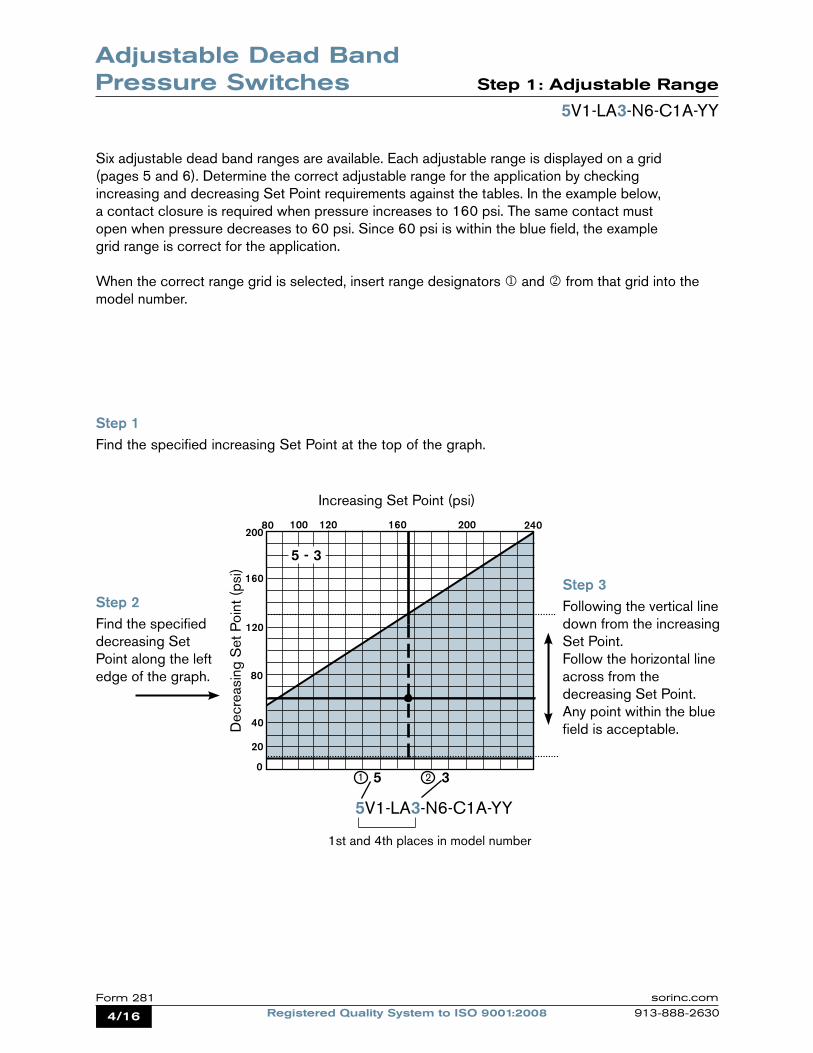
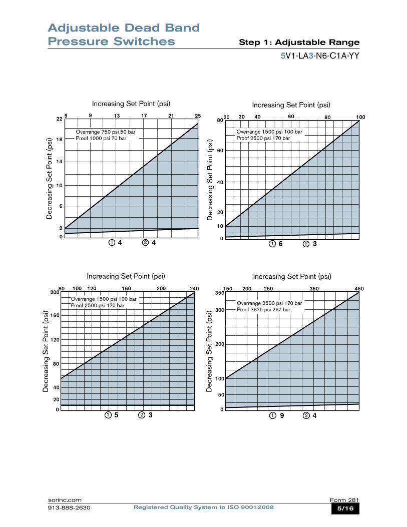
Six adjustable dead band ranges are available. Each adjustable range is displayed on a grid (pages 5 and 6). Determine the correct adjustable range for the application by checking increasing and decreasing Set Point requirements against the tables. In the example below, a contact closure is required when pressure increases to 160 psi. The same contact must open when pressure decreases to 60 psi. Since 60 psi is within the blue field, the example grid range is correct for the application.
When the correct range grid is selected, insert range designators and from that grid into the model number.
Step 1Find the specified increasing Set Point at the top of the graph.
Adjustable Dead Band Pressure Switches Step 1: Adjustable Range
5V1-LA3-N6-C1A-YY
5V1-LA3-N6-C1A-YY
Step 2Find the specified decreasing Set Point along the left edge of the graph.
Step 3 Following the vertical line down from the increasing Set Point. Follow the horizontal line across from the decreasing Set Point. Any point within the blue field is acceptable.
1st and 4th places in model number
1 25 30
20
40
80
120
160
20080 100 120 160 200
Dec
reas
ing
Set
Poi
nt (p
si)
240
Increasing Set Point (psi)
5 - 3
5/16Registered Quality System to ISO 9001:2008Form 281sorinc.com
913-888-2630
Adjustable Dead Band Pressure Switches Step 1: Adjustable Range
25
0
2
40
80
22 5 9 13 17
1 2
Dec
reas
ing
Set
Poi
nt (p
si)
0
50
100
200
300
150 200 250 350
Overrange 2500 psi 170 barProof 3875 psi 267 bar
1 2
Increasing Set Point (psi)
Overrange 750 psi 50 barProof 1000 psi 70 bar
4 4
21
18
14
10
6
9 4
Increasing Set Point (psi)
Dec
reas
ing
Set
Poi
nt (p
si)
5V1-LA3-N6-C1A-YY
450350
100
0
10
20
40
60
8020 30 40 60 80
1 2
Dec
reas
ing
Set
Poi
nt (p
si)
6 3
Increasing Set Point (psi)
Overrange 1500 psi 100 barProof 2500 psi 170 bar
1 25 30
20
40
80
120
160
20080 100 120 160 200
Dec
reas
ing
Set
Poi
nt (p
si)
240
Increasing Set Point (psi)
5 - 3Overrange 1500 psi 100 barProof 2500 psi 170 bar
6/16 Registered Quality System to ISO 9001:2008Form 281 sorinc.com
913-888-2630
0
100
200
400
600
800300 400 600 800
1 2
Dec
reas
ing
Set
Poi
nt (p
si)
1000
Increasing Set Point (psi)
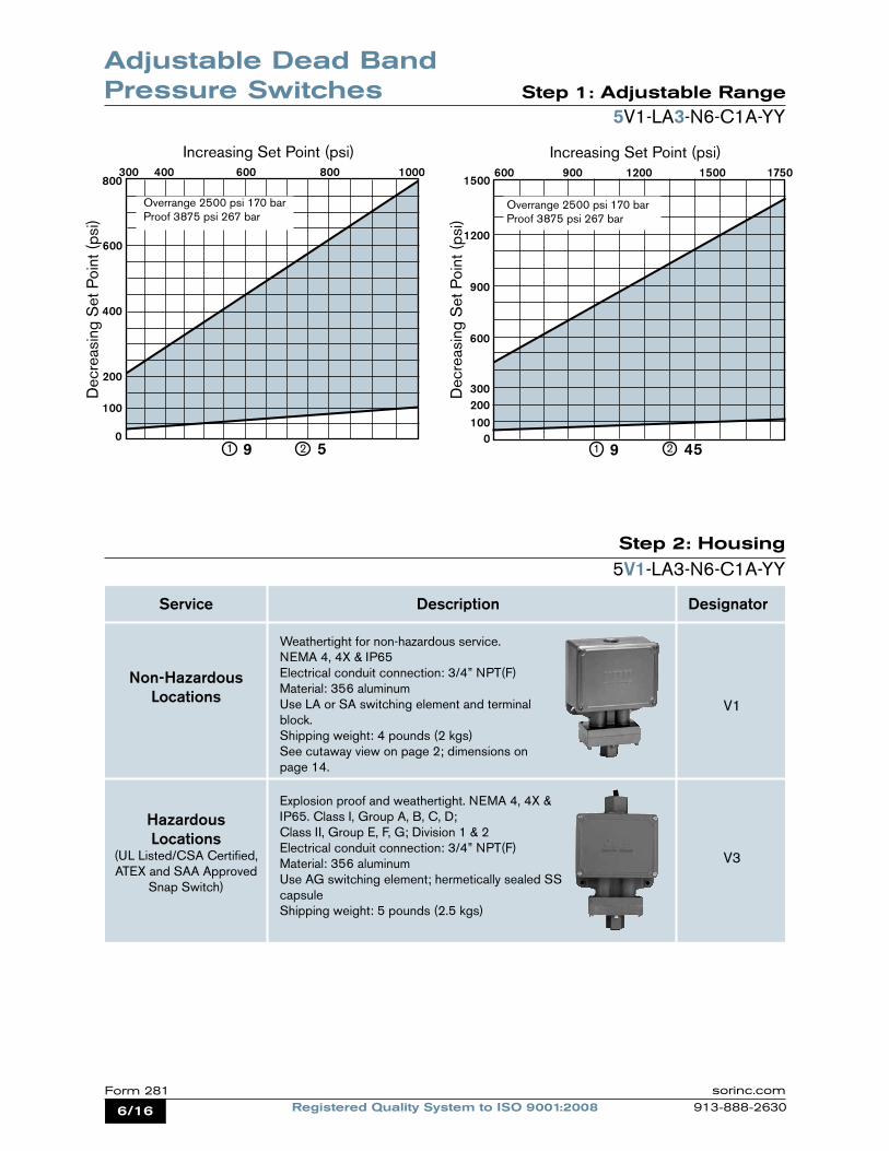
9 50
100200300
600
900
600 900 1200 1500
1 2D
ecre
asin
g S
et P
oint
(psi
)
1750
Increasing Set Point (psi)
9 45
1200
1500
Adjustable Dead Band Pressure Switches Step 1: Adjustable Range
Step 2: Housing
5V1-LA3-N6-C1A-YY
Service Description Designator
Non-Hazardous Locations
Hazardous Locations
(UL Listed/CSA Certified,ATEX and SAA Approved
Snap Switch)
Weathertight for non-hazardous service. NEMA 4, 4X & IP65Electrical conduit connection: 3/4” NPT(F)Material: 356 aluminumUse LA or SA switching element and terminal block.Shipping weight: 4 pounds (2 kgs)See cutaway view on page 2; dimensions on page 14.
V1
Explosion proof and weathertight. NEMA 4, 4X & IP65. Class I, Group A, B, C, D; Class II, Group E, F, G; Division 1 & 2Electrical conduit connection: 3/4” NPT(F)Material: 356 aluminumUse AG switching element; hermetically sealed SS capsuleShipping weight: 5 pounds (2.5 kgs)
V3
Overrange 2500 psi 170 barProof 3875 psi 267 bar
Overrange 2500 psi 170 barProof 3875 psi 267 bar
5V1-LA3-N6-C1A-YY
7/16Registered Quality System to ISO 9001:2008Form 281sorinc.com
913-888-2630
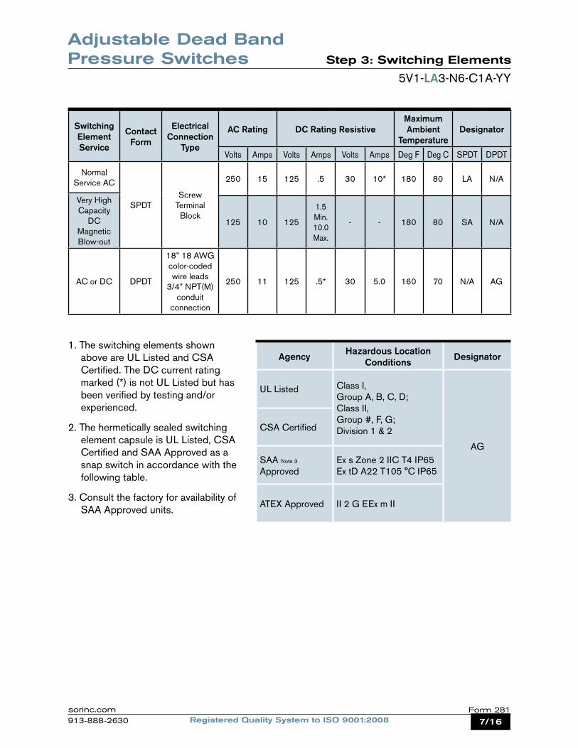
Adjustable Dead Band Pressure Switches Step 3: Switching Elements
5V1-LA3-N6-C1A-YY
1. The switching elements shown above are UL Listed and CSA Certified. The DC current rating marked (*) is not UL Listed but has been verified by testing and/or experienced.
2. The hermetically sealed switching element capsule is UL Listed, CSA Certified and SAA Approved as a snap switch in accordance with the following table.
3. Consult the factory for availability of SAA Approved units.
Agency Hazardous Location Conditions Designator
UL Listed Class I, Group A, B, C, D;Class II, Group #, F, G;Division 1 & 2
AG
CSA Certified
SAA Note 3
ApprovedEx s Zone 2 IIC T4 IP65Ex tD A22 T105 °C IP65
ATEX Approved II 2 G EEx m II
Switching Element Service
Contact Form
Electrical Connection
Type
AC Rating DC Rating ResistiveMaximum Ambient
TemperatureDesignator
Volts Amps Volts Amps Volts Amps Deg F Deg C SPDT DPDT
Normal Service AC
SPDTScrew
Terminal Block
250 15 125 .5 30 10* 180 80 LA N/A
Very High Capacity
DC Magnetic Blow-out
125 10 125
1.5 Min.10.0 Max.
- - 180 80 SA N/A
AC or DC DPDT
18” 18 AWG color-coded wire leads
3/4” NPT(M) conduit
connection
250 11 125 .5* 30 5.0 160 70 N/A AG
8/16 Registered Quality System to ISO 9001:2008Form 281 sorinc.com
913-888-2630
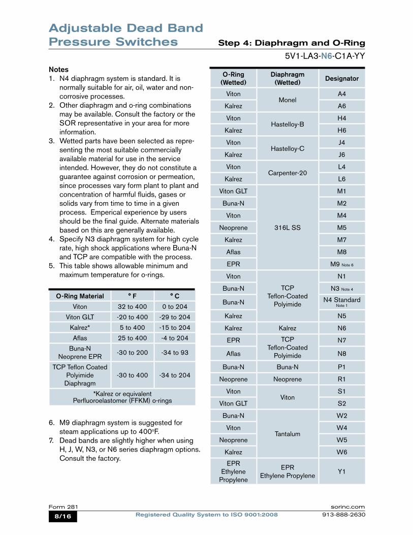
Adjustable Dead Band Pressure Switches Step 4: Diaphragm and O-Ring
5V1-LA3-N6-C1A-YY
Notes1. N4 diaphragm system is standard. It is
normally suitable for air, oil, water and non-corrosive processes.
2. Other diaphragm and o-ring combinations may be available. Consult the factory or the SOR representative in your area for more information.
3. Wetted parts have been selected as repre-senting the most suitable commercially
available material for use in the service intended. However, they do not constitute a guarantee against corrosion or permeation, since processes vary form plant to plant and concentration of harmful fluids, gases or
solids vary from time to time in a given process. Emperical experience by users
should be the final guide. Alternate materials based on this are generally available.
4. Specify N3 diaphragm system for high cycle rate, high shock applications where Buna-N and TCP are compatible with the process.
5. This table shows allowable minimum and maximum temperature for o-rings.
O-Ring (Wetted)
Diaphragm (Wetted) Designator
VitonMonel
A4
Kalrez A6
VitonHastelloy-B
H4
Kalrez H6
VitonHastelloy-C
J4
Kalrez J6
VitonCarpenter-20
L4
Kalrez L6
Viton GLT
316L SS
M1
Buna-N M2
Viton M4
Neoprene M5
Kalrez M7
Aflas M8
EPR M9 Note 6
Viton
TCP Teflon-Coated
Polyimide
N1
Buna-N N3 Note 4
Buna-N N4 Standard Note 1
Kalrez N5
Kalrez Kalrez N6
EPR TCP Teflon-Coated
Polyimide
N7
Aflas N8
Buna-N Buna-N P1
Neoprene Neoprene R1
VitonViton
S1
Viton GLT S2
Buna-N
Tantalum
W2
Viton W4
Neoprene W5
Kalrez W6
EPREthylene
Propylene
EPREthylene Propylene
Y1
O-Ring Material ° F ° C
Viton 32 to 400 0 to 204
Viton GLT -20 to 400 -29 to 204
Kalrez* 5 to 400 -15 to 204
Aflas 25 to 400 -4 to 204
Buna-N Neoprene EPR
-30 to 200 -34 to 93
TCP Teflon CoatedPolyimide
Diaphragm-30 to 400 -34 to 204
*Kalrez or equivalent Perfluoroelastomer (FFKM) o-rings
6. M9 diaphragm system is suggested for steam applications up to 400oF.
7. Dead bands are slightly higher when using H, J, W, N3, or N6 series diaphragm options. Consult the factory.
9/16Registered Quality System to ISO 9001:2008Form 281sorinc.com
913-888-2630
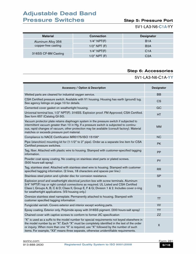
Step 5: Pressure Port
5V1-LA3-N6-C1A-YY
Material Connection Designator
Aluminum Alloy 356copper-free casting
1/4” NPT(F) B1A
1/2” NPT (F) B2A
316SS CF-8M Casting1/4” NPT(F) C1A
1/2” NPT (F) C2A
Adjustable Dead Band Pressure Switches
Step 6: Accessories
5V1-LA3-N6-C1A-YY
Accessory / Option & Description Designator
Wetted parts are cleaned for industrial oxygen service. BB
CSA Certified pressure switch. Available with V1 housing. Housing has earth (ground) lug. See agency listings on page 10 for details.
CS
Cemented cover gasket on weathertight housing. GC
Universal terminal box, 1/2” NPT(F). 316SS. Explosion proof. FM Approved; CSA Certified. See form 657 (Catalog GI-30).
HT
Vacuum protector plate retains diaphragm system in the pressure switch if subjected to intermittent vacuum greater than 10 in Hg. If a pressure switch is subjected to continu-ous, rapid changes of vacuum, other protection may be available (consult factory). Material matches or exceeds pressure port material.
MM
Compliance to NACE Certification MR0175/ISO 15156* NC
Pipe (stanchion) mounting kit for (1-1/2” to 2” pipe). Order as a separate line item for CSA Certified pressure switches.
PK
Tag, fiber. Attached with plastic wire to housing. Stamped with customer-specified tagging information.
PP
Powder coat epoxy coating. No coating on stainless steel parts or plated screws. (500 hours-salt spray)
PY
Tag, stainless steel. Attached with stainless steel wire to housing. Stamped with customer specified tagging information. (2 lines, 18 characters and spaces per line.)
RR
Stainless steel piston and cylinder disc for corrosion resistance. SP
Explosion proof and weathertight electrical junction box with screw terminals. Aluminum 3/4” NPT(F) top or right conduit connections as required. UL Listed and CSA Certified Class I, Groups A, B, C & D; Class II, Group E, F & G; Division 1 & 2. Includes cover o-ring for weathertight applications. (V3 housing only.)
TB
Oversize stainless steel nameplate. Permanently attached to housing. Stamped with customer specified tagging information
TT
Fungicidal varnish. Covers exterior and interior except working parts. VV
Epoxy coating. Exterior only. Polyimide epoxy with 316SS pigment. (200 hours-salt spray) YY
Chained cover with captive screws to conform to former JIC specification ZZ
“X” is used as a suffix to the model number for special requirements not keyed elsewhere in the model number by an “X”. Each “X” must be completely identified in the text of the order or inquiry. When more than one “X” is required, use “X” followed by the number of such items. For example, “X3” means three separate, otherwise unidentifiable requirements.
X
10/16 Registered Quality System to ISO 9001:2008Form 281 sorinc.com
913-888-2630
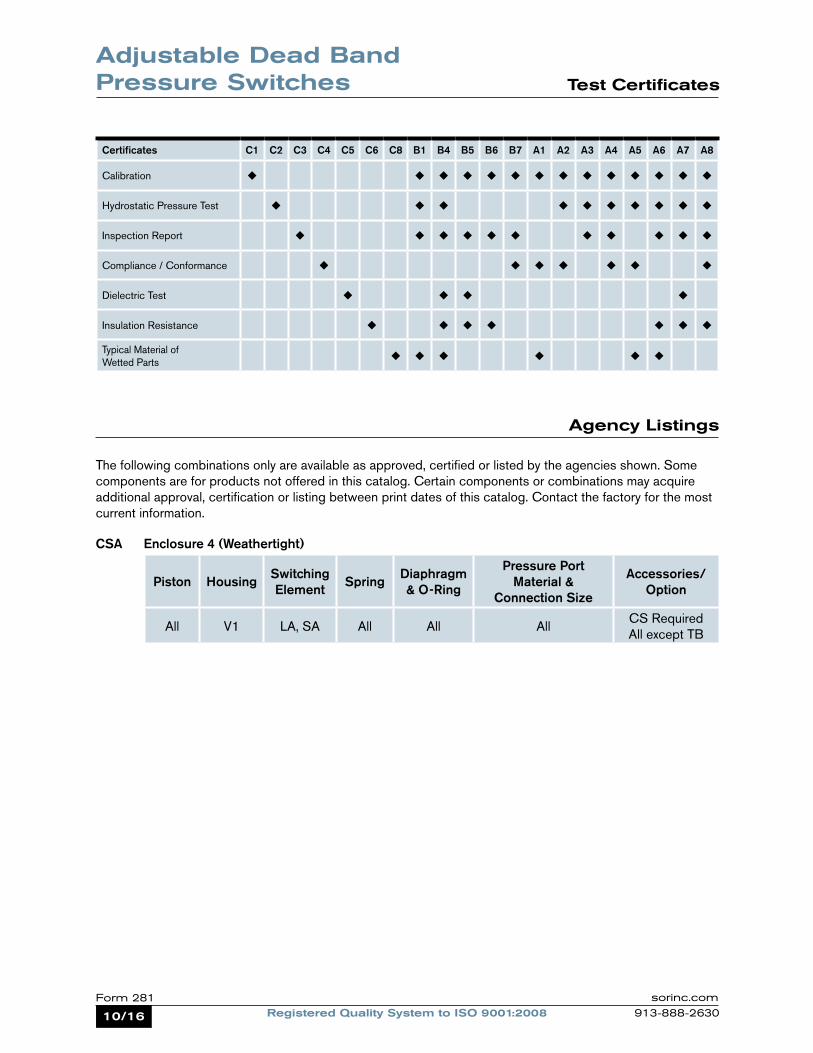
Agency Listings
The following combinations only are available as approved, certified or listed by the agencies shown. Some components are for products not offered in this catalog. Certain components or combinations may acquire additional approval, certification or listing between print dates of this catalog. Contact the factory for the most current information.
CSA Enclosure 4 (Weathertight)
Piston Housing Switching Element Spring Diaphragm
& O-Ring
Pressure Port Material &
Connection Size
Accessories/Option
All V1 LA, SA All All AllCS Required All except TB
Certificates C1 C2 C3 C4 C5 C6 C8 B1 B4 B5 B6 B7 A1 A2 A3 A4 A5 A6 A7 A8
Calibration ¿ ¿ ¿ ¿ ¿ ¿ ¿ ¿ ¿ ¿ ¿ ¿ ¿ ¿
Hydrostatic Pressure Test ¿ ¿ ¿ ¿ ¿ ¿ ¿ ¿ ¿ ¿
Inspection Report ¿ ¿ ¿ ¿ ¿ ¿ ¿ ¿ ¿ ¿ ¿
Compliance / Conformance ¿ ¿ ¿ ¿ ¿ ¿ ¿
Dielectric Test ¿ ¿ ¿ ¿
Insulation Resistance ¿ ¿ ¿ ¿ ¿ ¿ ¿
Typical Material of Wetted Parts ¿ ¿ ¿ ¿ ¿ ¿
Adjustable Dead Band Pressure Switches Test Certificates
11/16Registered Quality System to ISO 9001:2008Form 281sorinc.com
913-888-2630
Adjustable Dead Band Pressure Switches Glossary of Terms
SOR recognizes that there is no industry convention with respect to terminology and definitions pertinent to pressure switches. This glossary applies to SOR Pressure Switches.
Adjustable Range The span of pressure between upper and lower limits within which the pressure switch may be adjusted to actuate/deactuate.
Dead BandThe difference in pressure between the increasing Set Point and decreasing Set Point.
Decreasing Set PointThat discrete pressure at which the pressure switch is adjusted to deactuate on falling pressure. It must fall within the adjustable range.
Hermetically Sealed A welded steel capsule with glass-to-metal, factory-sealed, electrical leads that isolates the electrical switching element(s) from the environment.
Increasing Set PointThat discrete pressure at which the pressure switch is adjusted to actuate on rising pressure. It must fall within the adjustable range.
OverrangeThe maximum input pressure that may be continuously applied to the pressure switch without causing permanent change of Set Point, leakage or material failure.
Pressure SwitchA bi-stable electromechanical device that actuates/deactuates one or more electrical switching element(s) at a predetermined discrete pressure/vacuum (Set Point) upon rising or falling pressure/vacuum.
Proof Pressure The maximum input pressure that may be continuously applied to the pressure switch without causing leakage or catastrophic material failure. Permanent change of Set Point may occur, or the device may be rendered inoperative.
RepeatabilityThe ability of a pressure switch to successively operate at a Set Point that is approached from a starting point in the same direction and returns to the starting point over three consecutive cycles to establish a pressure profile. The closeness of the measured Set Point values is normally expressed as a percentage of full scale (maximum adjustable range pressure).
SPDT Switching Element Single-Pole, Double Throw (SPDT) has three connections: C — Common, NO — Normally Open and NC — Normally Closed, which allows the switching element to be electrically connected to the circuit in either NO or NC state.
DPDT Switching ElementDPDT is two synchronized SPDT switching elements which actuate together at increasing Set Point and deactuate together at decreasing Set Point. Discrete SPDT switching elements allow two independent circuits to be switched; i.e., one AC and one DC.
The synchronization linkage is factory set, and is not field adjustable. Synchronization is verified by connecting test lamps to the switching elements and observing them go “On” simultaneously at actuation and “Off” simultaneously at deactuation.
12/16 Registered Quality System to ISO 9001:2008Form 281 sorinc.com
913-888-2630
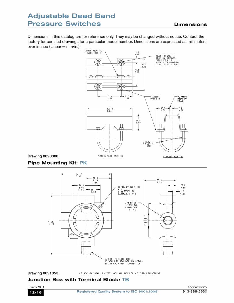
Adjustable Dead Band Pressure Switches Dimensions
Dimensions in this catalog are for reference only. They may be changed without notice. Contact the factory for certified drawings for a particular model number. Dimensions are expressed as millimeters over inches (Linear = mm/in.).
Pipe Mounting Kit: PK
Junction Box with Terminal Block: TB
Drawing 0090300
Drawing 0091353
13/16Registered Quality System to ISO 9001:2008Form 281sorinc.com
913-888-2630
Dimensions
Adjustable Dead Band Pressure Switches
Junction Box with Terminal Block: HT
Weights
Actual shipping weights may vary from the charted values because of product material, configuration and packaging requirements.
Drawing 0090763
V1 Housing V3 Housing
4 lbs (2 kgs) 5 lbs (2.5 kgs)
Accessory Add lbs kgs
Pk Pipe Kit 1.5 0.7
TB Junction box with Terminal Block
5 2.25
14/16 Registered Quality System to ISO 9001:2008Form 281 sorinc.com
913-888-2630
Non-Hazardous LocationsWeathertight NEMA 4, 4X, IP65Housing Designator: V1
Housing Dimensions
Adjustable Dead Band Pressure Switches
Hazardous LocationsContains Explosion Proof, Hermetically Sealed Switching Element Capsule: UL Listed, CSA Certified, ATEX and SAA Approved
Housing Designator: V3
Dimensions in this catalog are for reference only. They may be changed without notice. Contact the factory for certified drawings for a particular model number. Dimensions are expressed as millimeters over inches (Linear = mm/in.).
Drawing 0090236
Drawing 0090325
15/16Registered Quality System to ISO 9001:2008Form 281sorinc.com
913-888-2630
Notes
16/16 Registered Quality System to ISO 9001:2008Form 281 sorinc.com
913-888-2630Registered Quality System to ISO 9001:2008 Form 281 (03.12) ©2012 SOR Inc.
echOsonix® Level Transmitters
TemperatureSwitches
Pre
ssu
re
Flow
LevelLevel
Switches
Flow Switches
PressureSwitches
SOR® offers a full line of commercial-grade process instruments.
Tem
pera
ture
We Deliver Quality On Time
SOR Europe, Ltd.Farren CourtCowfoldWest Sussex RH13 8BPUnited Kingdom
Phone +44 (0) 1403 864000Fax +44 (0) 1403 864040
SOR - ChinaRoom 903, No. 10 Building Wan Da Plaza No. 93 Jian Guo RoadChao Yang DistrictBeijing, China 100022
Phone +86 (10) 5820 8767Fax +86 (10) 58 20 8770
SOR Inc.14685 West 105th StreetLenexa, Kansas 66215
Phone 913-888-2630Toll Free 800-676-6794Fax 913-888-0767
sorinc.com
Process Instrumentation
Form 466 (05.13) ©SOR Inc. 1/4
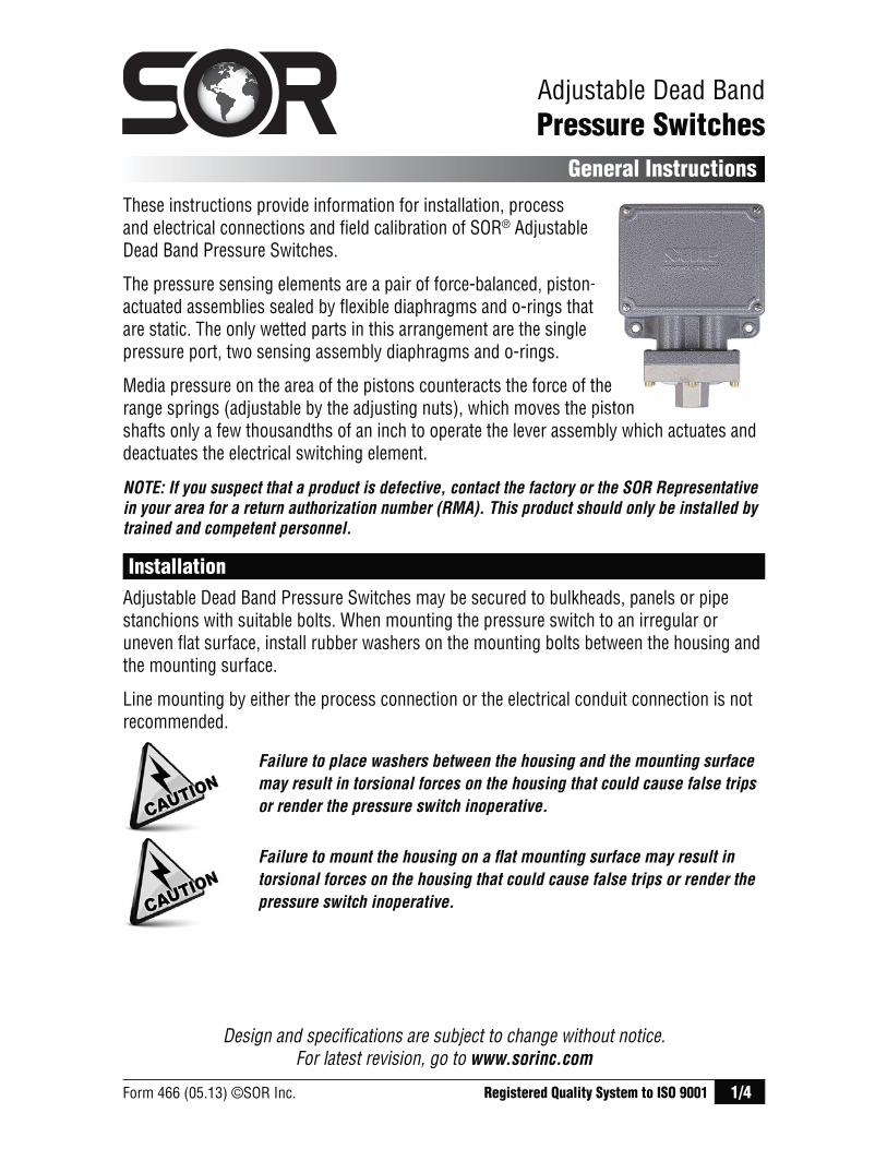
These instructions provide information for installation, process and electrical connections and field calibration of SOR® Adjustable Dead Band Pressure Switches.
The pressure sensing elements are a pair of force-balanced, piston-actuated assemblies sealed by flexible diaphragms and o-rings that are static. The only wetted parts in this arrangement are the single pressure port, two sensing assembly diaphragms and o-rings.
Media pressure on the area of the pistons counteracts the force of the range springs (adjustable by the adjusting nuts), which moves the piston shafts only a few thousandths of an inch to operate the lever assembly which actuates and deactuates the electrical switching element.
Adjustable Dead BandPressure Switches
General Instructions
Failure to place washers between the housing and the mounting surface
may result in torsional forces on the housing that could cause false trips
or render the pressure switch inoperative.
Registered Quality System to ISO 9001
NOTE: If you suspect that a product is defective, contact the factory or the SOR Representative
in your area for a return authorization number (RMA). This product should only be installed by
trained and competent personnel.
Installation
Adjustable Dead Band Pressure Switches may be secured to bulkheads, panels or pipe stanchions with suitable bolts. When mounting the pressure switch to an irregular or uneven flat surface, install rubber washers on the mounting bolts between the housing and the mounting surface.
Line mounting by either the process connection or the electrical conduit connection is not recommended.
Design and specifications are subject to change without notice. For latest revision, go to www.sorinc.com
-t
the piston
Failure to mount the housing on a fl at mounting surface may result in
torsional forces on the housing that could cause false trips or render the
pressure switch inoperative.
2/4 Form 466 (05.13) ©SOR Inc.
Process Connection
Securely connect the process line to the pressure port using two wrenches: one to hold the hexagonal flats on the pressure port, the other to tighten the process pipe or tube fitting.
Ensure that the process connection is tightened and positioned so that
any binding and torsional forces imposed on the pressure switch are
minimal. Do not loosen the pressure port from the body because leakage
could result or the pressure switch could be rendered inoperative.
Electrical Connection
Ensure that wiring conforms to all applicable local and national electrical codes and install unit(s) according to relevant national and local safety codes.
V1 – Weathertight SPDT: Screw terminal block with marked insulation.
Common Normally Open Normally Closed
C1 NO1 NC1
V3 – Explosion proof DPDT (2-SPDT): Hermetically sealed switching element capsule has 18” - 18 AWG wire leads color coded and marked.
Common Normally Open Normally Closed
C1 - Blue NO1 - Black NC1 - Red C2 - Yellow NO2 - Brown NC2 - Orange
GR - Ground (earth) green wire connected to each hermetically sealed switching element capsule.
Calibration
Remove the housing cover. Connect a suitable variable pressure source with a calibrated reference gauge to the pressure port. Connect an ohmmeter or test lamp across the switching element contact terminals to monitor contact continuity. Use a 3/4” open-end wrench to turn the adjusting nuts. Slowly increase pressure to the pressure port. The continuity tester will indicate that the contacts have changed state when increasing set point is reached. Note pressure at increasing set point. If increasing set point is too low, turn the left adjusting nut clockwise to raise the increasing set point. If increasing set point is too high, turn the left adjusting nut counterclockwise to lower the increasing set point.
Safety Integrity Level (SIL) Installation Requirements
The SOR pressure switches have been evaluated as Type-A safety related hardware. To meet the necessary installation requirements for the SIL system, the following information must be utilized:
Proof Test Interval shall be one year. Units may only be installed for use in Low Demand Mode. Products have a HFT (Hardware Fault Tolerance) of 0, and were evaluated in a
1oo1 (one out of one) configuration. Form 1538 (03.12) ©2012 SOR Inc.
Form 466 (05.13) ©SOR Inc. 3/4
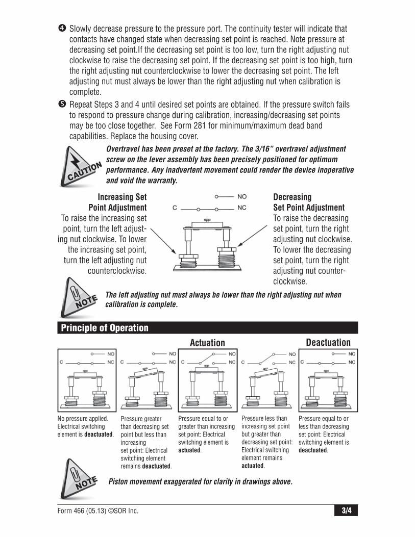
Overtravel has been preset at the factory. The 3/16” overtravel adjustment
screw on the lever assembly has been precisely positioned for optimum
performance. Any inadvertent movement could render the device inoperative
and void the warranty.
The left adjusting nut must always be lower than the right adjusting nut when
calibration is complete.
Slowly decrease pressure to the pressure port. The continuity tester will indicate that contacts have changed state when decreasing set point is reached. Note pressure at decreasing set point.If the decreasing set point is too low, turn the right adjusting nut clockwise to raise the decreasing set point. If the decreasing set point is too high, turn the right adjusting nut counterclockwise to lower the decreasing set point. The left adjusting nut must always be lower than the right adjusting nut when calibration is complete. Repeat Steps 3 and 4 until desired set points are obtained. If the pressure switch fails to respond to pressure change during calibration, increasing/decreasing set points may be too close together. See Form 281 for minimum/maximum dead band capabilities. Replace the housing cover.
Principle of Operation
No pressure applied. Electrical switching element is deactuated.
Pressure greater than decreasing set point but less than increasing set point: Electrical switching element remains deactuated.
Pressure equal to or greater than increasing set point: Electrical switching element is actuated.
Pressure less than increasing set point but greater than decreasing set point: Electrical switching element remains actuated.
Pressure equal to or less than decreasing set point: Electrical switching element is deactuated.
Actuation Deactuation
Piston movement exaggerated for clarity in drawings above.
Increasing Set
Point Adjustment
To raise the increasing set point, turn the left adjust-
ing nut clockwise. To lower the increasing set point,
turn the left adjusting nut counterclockwise.
Decreasing
Set Point Adjustment
To raise the decreasing set point, turn the right adjusting nut clockwise. To lower the decreasing set point, turn the right adjusting nut counter-clockwise.
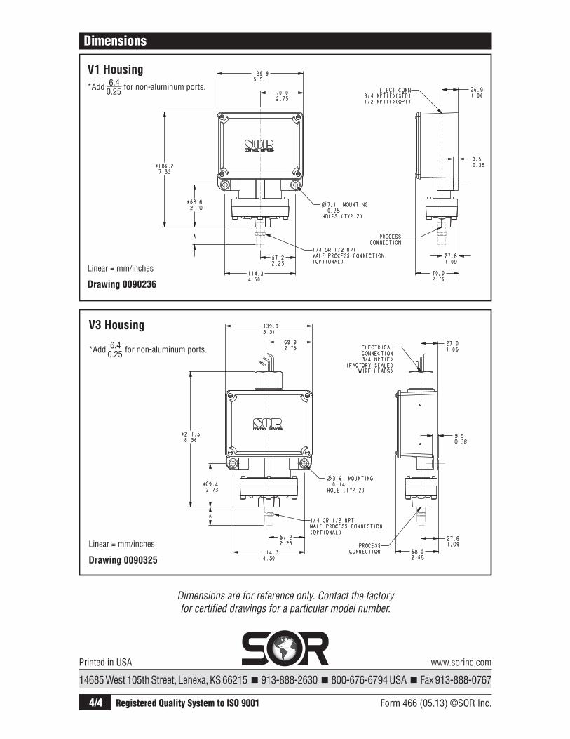
4/4 Form 466 (05.13) ©SOR Inc.
Dimensions
Dimensions are for reference only. Contact the factory for certified drawings for a particular model number.
Linear = mm/inches
Drawing 0090236
Linear = mm/inches
Drawing 0090325
14685 West 105th Street, Lenexa, KS 66215 913-888-2630 800-676-6794 USA Fax 913-888-0767
Registered Quality System to ISO 9001
Printed in USA www.sorinc.com
V1 Housing
V3 Housing
*Add 6.4 for non-aluminum ports.
0.25
*Add 6.4 for non-aluminum ports.
0.25
SOR Form 506 (04.05) Printed in USA Page 1 of 4
This product should only be installed by trained and competent personnel.
1. Secure the housing to a bulkhead, panel rack or pipe stanchion with suitable bolts.
IMPORTANT: When bolting housings with integral mounting pads to irregular or uneven surfaces, install rubber washers between the housing and the mounting surface to prevent deformation of the housing.
General
These instructions provide information for installation, electrical connection, process connection and calibration of Series 101/121 Differential Pressure Switches.
B-Series models (B3, B4, B5, B6) may be ATEX Approved with the addition of a CL option at the end of the model string. Specific information and instructions concerning these models will be found throughout the following pages.
NOTE: SOR discourages field modifications and field repair. Products should be returned to SOR for inspection and necessary repair work. Contact the factory for a return authorization number. Any field work should be performed by qualified instrument technicians using factory-authorized procedures.
Principle of OperationProcess pressure is sensed by a diaphragm and piston assembly. The piston responds to differential pressure and moves a shaft that actuates (deactuates) an electrical switching element. Low side pressure and an adjustable range spring oppose high side pressure. Adjustment of the range spring determines the set point. (See Calibration.)
CAUTION: Use care during installation to avoid moving the electrical switching element or its housing. Movement of either could change calibration or render the device inoperative.
Design and specifications are subject to change without notice.
Series 101/121
Differential Pressure Switches
Installation Electrical Connection
CAUTION: Failure to mount the housing on a flat mounting surface may result in torsional forces on the housing that could cause false trips or render the pressure switch inoperative.
2. Line mounting by either process connection or electrical conduit connection is not recommended for housings with integral mounting pads.
3. Suggested mounting orientation is high side process pressure port at 6 o’clock. However, the device can be mounted in any position. Optional breather drains should be positioned to allow moisture to escape from the housing interior. Breather drains must be kept clear of paint and foreign matter.
CAUTION: For B-Series Housings One vent hole should be fitted with a suitable breather to maintain weathertight rating NEMA 4, 4X, IP65 or vented to a safe area. Piping should be minimum 1/4” diameter and maximum 5 meters long (based on process fluid SG 1.0). The other vent hole may be plugged.
Process Connection
Connect the process lines to the pressure ports using two wrenches: one to hold the hex flats on the pressure port, the other to tighten the process pipe or tube fitting. The high pressure side (stamped HI) and the low pressure side (stamped LO) have 1/4” NPT(F) or 1/4” BSP(F) process connections as standard.
IMPORTANT: Rigid process piping must be arranged to minimize bending or twisting forces which could disturb the positioning of internal parts and change calibration or render the device inoperative after installation. Use care to avoid loosening the pressure port from the body or the body from the electrical housing.
Ensure that wiring conforms to all applicable local and national electrical codes and install unit(s) according to relevant national and local safety codes.
NOTE: For B-Series ATEX Certified ModelsElectrical conduit connection threads may be of non-ISO thread form. Check the product nametag for relevant thread form information before attempting to connect to the electrical conduit connection. In the event a fitting is used, check the adaptor body for thread size information.
General Instructions
For latest revision, see www.sorinc.comRegistered Quality System to ISO 9001
Mini-Hermet Models General Purpose and Weathertight
Models
B-Series Models

Page 2 of 4 SOR Form 506 (04.05) Printed in USA
Calibration
Mini-Hermet modelsRemove the weathertight cap. Use a 1/8” hex Allen wrench to turn the adjusting screw to the desired set point. Turn the adjusting screw clockwise (in) to increase the set point and counterclockwise (out) to decrease the set point. Use either the coarse or the precise set point calibration procedure.
CAUTION: Do not unthread the adjusting screw more than two threads below the flush point of housing as calibration could be adversely affected.
All Other ModelsUse a 3/4-inch open-end wrench to turn hex adjusting nut clockwise to increase set point, and counterclockwise to decrease set point. An approximate set point can be obtained by sighting across top of adjusting nut to the calibration scale
on the interior wall of the housing. If coarse or precise set point calibration is required, calibrate according to the appropriate procedure.
WARNING: For B-Series Housings The electrical compartment cover must remain sealed and the Allen locking screw tightened at all times to prevent removal of the cover while the pressure switch is in service. Removal of the cover while the pressure switch is in service in a hazardous location could result in severe personal injury or substantial property damage.
Coarse Calibration Procedure1. Connect variable pressure source to test gauge and HI
side pressure port.2. Connect test light or ohmmeter across C – Common
and NO – Normally Open switching element contacts.3. Raise pressure and note test gauge reading when
circuit closes.4. Slowly drop pressure and note test gauge reading
when circuit opens.5. Turn set point adjustment clockwise to increase set
point, or counterclockwise to decrease set point.6. Repeat Steps 3, 4 and 5 until contacts change at desired
increasing or decreasing differential pressure set point.
Precise Calibration ProcedureThe precise calibration procedure references system (static) pressure. Set point accuracy is enhanced by calibrating the differential pressure switch under simulated service pressure conditions. The following test apparatus is recommended.
1. Differential pressure gauge2. Variable pressure source 3. Block/bleed and equalizer valves4. Test light or ohmmeter
Determine whether the critical set point occurs on increasing or decreasing differential pressure, and calibrate using the appropriate procedure:
For Critical Set Point on Increasing Differential Pressure1. Connect the continuity test lamp or ohmmeter across
the C - Common and NO - Normally Open switching element / contacts.
2. Close the bleed valve(s), open the equalizer valve and raise pressure equally on both HI and LO sides to the static pressure that the differential pressure switch will see under normal operating conditions.
3. With static pressure stable, close the equalizer valve to isolate the HI side from the LO side.
4. Keeping high side pressure steady, slightly open the LO side bleed valve to reduce the LO side pressure (increase differential pressure) until desired differential pressure set point appears on indicator. Close bleed valve to stabilize differential pressure. Check the status of the electrical contacts against the following differential pressure trend graphs. Follow the instructions under the graph that matches the status of the contacts.
See SOR Form 468 for reference dimension drawings. For certified dimension drawings contact factory.
Wire Lead Color CodeBlue (C)Black (NO)Red (NC)
SPDT
NOTE: Storing excess wire or making wire lead splices inside the pressure switch housing should not be done and may interfere with the pressure switch operation.
DPDT (2-SPDT)
DifferentialPressure
HI
HINo. 1
DifferentialPressure
Blue (C)Black (NO)Red (NC)Yellow (C2)Brown (NO2)Orange (NC2)
No. 2
LO
LO
FIGURE 1
CAUTION: Electrical power must be disconnected from explosion proof models before the cover is removed. Failure to do so could result in severe personal injury or substantial property damage.
When making electrical connections, use care to avoid movement of the electrical switching element.
Electrical connections are either screw terminals, terminal blocks or 18-gauge, 18-inch wire leads.
Screw terminal and terminal block points are identified on the insulation card inside the electrical housing. Refer to the wiring schematic in Figure 1 for wire lead color codes.
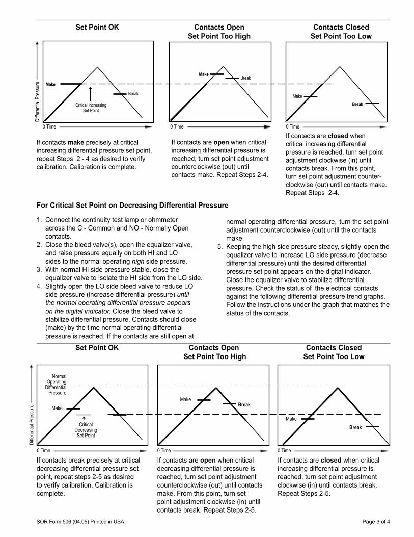
SOR Form 506 (04.05) Printed in USA Page 3 of 4
If contacts make precisely at critical increasing differential pressure set point, repeat Steps 2 - 4 as desired to verify calibration. Calibration is complete.
If contacts are open when critical increasing differential pressure is reached, turn set point adjustment counterclockwise (out) until contacts make. Repeat Steps 2-4.
If contacts are closed when critical increasing differential pressure is reached, turn set point adjustment clockwise (in) until contacts break. From this point, turn set point adjustment counter-clockwise (out) until contacts make. Repeat Steps 2-4.
Contacts Closed Set Point Too Low
Contacts Open Set Point Too High
Set Point OK
Critical Increasing Set Point
Make
Break
BreakMake
BreakMake
0 Time 0 Time0 Time
1. Connect the continuity test lamp or ohmmeter across the C - Common and NO - Normally Open contacts.
2. Close the bleed valve(s), open the equalizer valve, and raise pressure equally on both HI and LO sides to the normal operating high side pressure.
3. With normal HI side pressure stable, close the equalizer valve to isolate the HI side from the LO side.
4. Slightly open the LO side bleed valve to reduce LO side pressure (increase differential pressure) until the normal operating differential pressure appears on the digital indicator. Close the bleed valve to stabilize differential pressure. Contacts should close (make) by the time normal operating differential
pressure is reached. If the contacts are still open at
normal operating differential pressure, turn the set point adjustment counterclockwise (out) until the contacts make.
5. Keeping the high side pressure steady, slightly open the equalizer valve to increase LO side pressure (decrease differential pressure) until the desired differential
pressure set point appears on the digital indicator. Close the equalizer valve to stabilize differential pressure. Check the status of the electrical contacts
against the following differential pressure trend graphs. Follow the instructions under the graph that matches the status of the contacts.
For Critical Set Point on Decreasing Differential Pressure
0 Time
Contacts Closed Set Point Too Low
Contacts Open Set Point Too High
Set Point OK
If contacts break precisely at critical decreasing differential pressure set point, repeat steps 2-5 as desired to verify calibration. Calibration is complete.
If contacts are open when critical decreasing differential pressure is reached, turn set point adjustment counterclockwise (out) until contacts make. From this point, turn set point adjustment clockwise (in) until contacts break. Repeat Steps 2-5.
If contacts are closed when critical increasing differential pressure is reached, turn set point adjustment clockwise (in) until contacts break. Repeat Steps 2-5.
0 Time
MakeBreak
Make
0 Time
Break
Normal Operating
Differential Pressure
Make
Critical Decreasing Set Point
Diffe
renti
al Pr
essu
reDi
ffere
ntial
Pres
sure
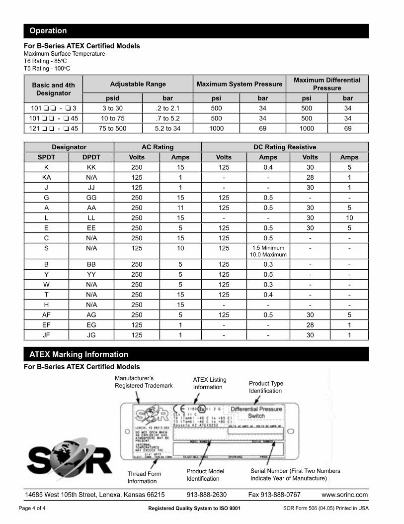
Page 4 of 4 SOR Form 506 (04.05) Printed in USA
14685 West 105th Street, Lenexa, Kansas 66215 913-888-2630 Fax 913-888-0767 www.sorinc.com
Registered Quality System to ISO 9001
Operation
For B-Series ATEX Certified ModelsMaximum Surface TemperatureT6 Rating - 85oCT5 Rating - 100oC
For B-Series ATEX Certified ModelsManufacturer’sRegistered Trademark
ATEX Listing Information Product Type
Identification
Thread Form Information
Product Model Identification
Serial Number (First Two Numbers Indicate Year of Manufacture)
ATEX Marking Information
Basic and 4th Designator
Adjustable Range Maximum System Pressure Maximum Differential Pressure
psid bar psi bar psi bar101 - 3 3 to 30 .2 to 2.1 500 34 500 34
101 - 45 10 to 75 .7 to 5.2 500 34 500 34121 - 45 75 to 500 5.2 to 34 1000 69 1000 69
Designator AC Rating DC Rating ResistiveSPDT DPDT Volts Amps Volts Amps Volts Amps
K KK 250 15 125 0.4 30 5KA N/A 125 1 - - 28 1J JJ 125 1 - - 30 1G GG 250 15 125 0.5 - -A AA 250 11 125 0.5 30 5L LL 250 15 - - 30 10E EE 250 5 125 0.5 30 5C N/A 250 15 125 0.5 - -S N/A 125 10 125 1.5 Minimum
10.0 Maximum- -
B BB 250 5 125 0.3 - -Y YY 250 5 125 0.5 - -W N/A 250 5 125 0.3 - -T N/A 250 15 125 0.4 - -H N/A 250 15 - - - -AF AG 250 5 125 0.5 30 5EF EG 125 1 - - 28 1JF JG 125 1 - - 30 1