Embed Size (px)
Citation preview
1Nttced[ifhptbfhgiw
tcwsttnhlu[
fcpitfn
C. J. Zapata-Rodríguez and J. J. Miret Vol. 27, No. 3 /March 2010/J. Opt. Soc. Am. A 663
Diffraction-free beams in thin films
Carlos J. Zapata-Rodríguez1,* and Juan J. Miret2
1Departamento de Óptica, Universidad de Valencia, Dr. Moliner 50, 46100 Burjassot, Spain2Departamento de Óptica, Universidad de Alicante, P.O. Box 99, Alicante, Spain
*Corresponding author: [email protected]
Received October 27, 2009; accepted January 15, 2010;posted January 20, 2010 (Doc. ID 119137); published February 26, 2010
The propagation and transmission of Bessel beams through nano-layered structures has been discussed re-cently. Within this framework we recognize the formation of unguided diffraction-free waves with the spot sizeapproaching and occasionally surpassing the limit of a wavelength when a Bessel beam of any order n islaunched onto a thin material slab with grazing incidence. On the basis of the plane-wave representation ofcylindrical waves, a simple model is introduced providing an exact description of the transverse pattern of thistype of diffraction-suppressed localized wave. Potential applications in surface science are put forward forconsideration. © 2010 Optical Society of America
OCIS codes: 260.0260, 310.6870, 350.5500.
bTpwgil
2Tda
wacccymsHn�=ttom[
e
. INTRODUCTIONondiffracting Bessel beams are associated with solu-
ions of the Helmholtz wave equation in free space whoseransverse amplitude distribution is written in cylindricaloordinates as the product of a linear phase functionxp�in�� depending on the azimuthal coordinate and a ra-ially varying Bessel function of the first kind and order n1]. The maximum value of the zero-order Bessel functions attained at the origin; however, higher-order Besselunctions have a phase singularity at r=0, reaching itsighest intensity nearby [2]. Its significance relies on theossibility of engineering laser beams reaching high in-ensities in a reduced area without diffraction-inducedlurring. In particular, the envelope of the Bessel functionalls off as 1/�r, which leads to an electromagnetic fieldaving an intensity distribution that is not square inte-rable [3]. As a consequence finite-energy practical real-zations of Bessel beams show axial bounds betweenhich diffraction-free propagation is valid [4–8].The propagation and transmission of Bessel beams
hrough nano-layered structures has been discussed re-ently [9–12] in the context of superluminality in opticalave packets [13–17]. However, an important attribute
uch as diffraction-free propagation is maintained only ifhe optical axis of the beam is parallel to the medium in-erfaces [18–20]. Guided waves in planar linear [21] andonlinear [22] waveguides are of this kind of modal fieldaving exponentially decaying tails far beyond the core
ayer. In general this condition relies on grazing incidencepon the interfaces, which may be used to study surfaces
23] by increasing wave penetration.In this paper we conveniently introduce a simple model
rom which high-order Bessel beams are interpreted as aoherent superposition of propagating and counter-ropagating waves along a direction (normal to the layernterfaces). In fact this sort of cylindrical wave localiza-ion is essentially understood as the generation of a lineocus around the z axis with 2� illumination. We recog-ize the formation of diffraction-free waves when a Bessel
1084-7529/10/030663-8/$15.00 © 2
eam of any order n is launched onto a thin material slab.he resultant optical beam has in general a twin-peakattern whose spot sizes even surpasses the limit of aavelength. From a geometrical approach the thin filmives rise to a pair of line images associated with wavesmpinging onto either the left or the right face of theayer.
. VECTOR BESSEL BEAMShe electric and magnetic fields of a monochromaticiffraction-free wave traveling in a homogeneous mediumre written using the modal function ansatz
E�x,y,z,t� = e�x,y�exp�i�z − i�t�, �1a�
H�x,y,z,t� = h�x,y�exp�i�z − i�t�, �1b�
here � is the time-domain frequency of the radiationnd ��0 is the propagation constant along the z axis. Weonsider a non-absorbing medium with positive dielectriconstant ���0�, zero magnetic susceptibility, and free ofharges. Let us assume a polarized wave such that the-component of the electric field vanishes, Ey=0; comple-entary polarized waves with Hy=0 may be obtained
traightforwardly by substituting �0↔�0�, E→H, and→−E. Faraday’s law leads to the estimation of the mag-
etic field in terms of the electric field, H= �−i /��0��E. Furthermore we obtain the equation Ezi�−1��Ex /�x� from Coulomb’s law. Therefore we may use
he two-dimensional scalar function U�x ,y��ex in ordero describe the wave mode unambiguously. Let us pointut that alternate routes for the description of electro-agnetic diffraction-free beams may be found elsewhere
24–26].The function U�x ,y� satisfies the differential wave
quation
010 Optical Society of America
wl(watmtw==
3LIdFtw
acdi�sstlo
ADFtpiipyid
ao
Cpc
F=
Flg=
664 J. Opt. Soc. Am. A/Vol. 27, No. 3 /March 2010 C. J. Zapata-Rodríguez and J. J. Miret
�2U
�x2 +�2U
�y2 + �k2 − �2�U = 0, �2�
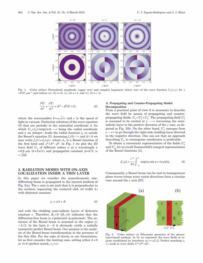
here the wavenumber k=��� /c and c is the speed ofight in vacuum. Particular solutions of the wave equation2) that are periodic in the azimuthal coordinate �, forhich Un= fn�r�exp�in�� —r being the radial coordinatend n an integer—leads the radial function fn to satisfyhe Bessel’s equation [1]. Assuming fn�0� and �k weay write fn�r�=Jn��r�, where Jn is a Bessel function of
he first kind and �2=k2−�2. In Fig. 1 we plot the 2Dave field Un of different orders n at a wavelength �0.6 �m �k=2� /�� and propagation constant �=k /2 ���3��.
. RADIATION MODES WITH ON-AXISOCALIZATION INSIDE A THIN LAYER
n this paper we consider the monochromatic non-iffracting beam is propagated in the layered medium ofig. 2(a). The y axis is set such that it is perpendicular to
he surfaces separating the centered slab (of width L)ith dielectric constant
�c = ��1 + � �3�
nd with the cladding semi-infinite layers of dielectriconstant �. Therefore, Ey=0 �Hy=0� indicates that theiffraction-free beam is s-polarized (p-polarized). The ex-stence of the Bessel beam is assumed in the region �y�
L /2. In the limit L→0 it obviously yields a radiallyymmetric perfect Bessel beam. Our purpose is the analy-is of the Bessel-beam transformation in the presence ofhe thin film. For the sake of clarity in our formulation,et us first consider the limiting case, setting either L=0r =0 (perfect match, � =�).
y (µm)
x(µm)
x(µm)
n = 0
(a)
(b)
-1.0 -0.5 0.0 0.5 1.0-1.0
-0.5
0.0
0.5
1.0
-1.0 -0-1.0
-0.5
0.0
0.5
1.0
-1.0 -0-1.0
-0.5
0.0
0.5
1.0
-1.0 -0.5 0.0 0.5 1.0-1.0
-0.5
0.0
0.5
1.0
ig. 1. (Color online) Normalized amplitude (upper row) and9.07 �m−1 and indices (a), (b) n=0, (c), (d) n=1, and (e), (f) n=−
c
. Propagating and Counter-Propagating Modalecompositionrom a practical point of view it is necessary to describe
he wave field by means of propagating and counter-ropagating fields, Un=Un
++Un−. The propagating field Un
+
s assumed to be excited at y→− traversing the semi-nfinite layer in the positive direction of the y axis, as de-icted in Fig. 2(b). On the other hand, Un
− emerges from→+ to go through the right-side cladding layer directed
n the negative direction. One can see that an approachescribing Un in rectangular coordinates is preferable.To obtain a convenient representation of the fields Un
+
nd Un−, let us recall Sommerfeld’s integral representation
f the Bessel functions [1],
Jn��� =i−n
2��
−�
�
exp�i� cos � + in��d�. �4�
onsequently, a Bessel beam can be cast in homogeneouslane waves whose wave vector directions form a circularone around the z axis [27]:
m) y (µm)
1 n = -2
(c) (e)
(d) (f)
0.5 1.0 -1.0 -0.5 0.0 0.5 1.0-1.0
-0.5
0.0
0.5
1.0
-1.0 -0.5 0.0 0.5 1.0-1.0
-0.5
0.0
0.5
1.0
0.5 1.0
lex argument (lower row) of the wave function Un�x ,y� for �
ε εcL
x
y
z
ε εc
y
U+ U-
L/2-L/2
R+R-F-
F+
(a) (b)
ε
ε
ig. 2. (Color online) (a) Schematic geometry of the planar-ayer-based medium. In (b) we represent the wave fields in re-ions established by interfaces at y= ±L /2. Perfect matching �c� leads to wave fields U±=F±=R±..
y (µ
n =
.5 0.0
.5 0.0
comp2.
DwWypwtEc
w
a
(axtpc
tsU
sowJa
wIbtesntFcp
BLbwscpygfit
Ft
C. J. Zapata-Rodríguez and J. J. Miret Vol. 27, No. 3 /March 2010/J. Opt. Soc. Am. A 665
Un =i−n
2���−�
0
+�0
� �expin� + i��x cos � + y sin ��d�.
�5�
enoting � the angle measuring the aperture of the conee obtain �=k sin � and �=k cos �. In Fig. 1 �=60 deg.hen 0��, the projection of the wave vector onto theaxis, � sin �, is positive, representing a wave field whosehase advances toward positive values of y; this shall beritten as Un
+. Otherwise � sin �0 for −��0 leadingo a counter-propagating field, Un
−. Setting kx=� cos � inq. (5) we obtain a 1D Fourier representation of the fieldomponents,
Un±�x,y� =
1
2��
−�
�
Un±�kx�exp� ± ikyy�exp�ikxx�dkx, �6�
here the spatial spectrum
Un±�kx� = i−n
�kx ± iky�n
ky�n , �7�
nd ky=��2−kx2.
We point out that the cylindrical wave U0 given in Eq.5) for n=0 may be essentially understood as anberration-free 2D focused field with focus at the origin,=y=0, using 2� illumination. Setting n�=k� allows uso identify the aberration function [28] � that would de-end linearly upon the Bessel index n and the azimuthaloordinate �.
Let us conclude our analysis of Un± by giving some func-
ional expressions for its fast computation. For nonab-orbing dielectric media ���0� we obtain the relation˜ − n ˜ + *
n= �−1� �Un� . This means that iUn−�x,y� = �− 1�nUn
+�− x,y�*, �8�
o that propagating and counter-propagating componentsf the Bessel wave functions possess mirror symmetryith respect to the plane x=0. Furthermore, using theacobi–Anger expansion [2] in Eq. (5) we may obtain thenalytical expression
Un+�x,y� =
1
2 �m=−
sinc�m − n�/2Um�x,y�, �9�
here the function sinc�u�=sin��u� / ��u� and sinc�0�=1.n Fig. 3 we represent Un
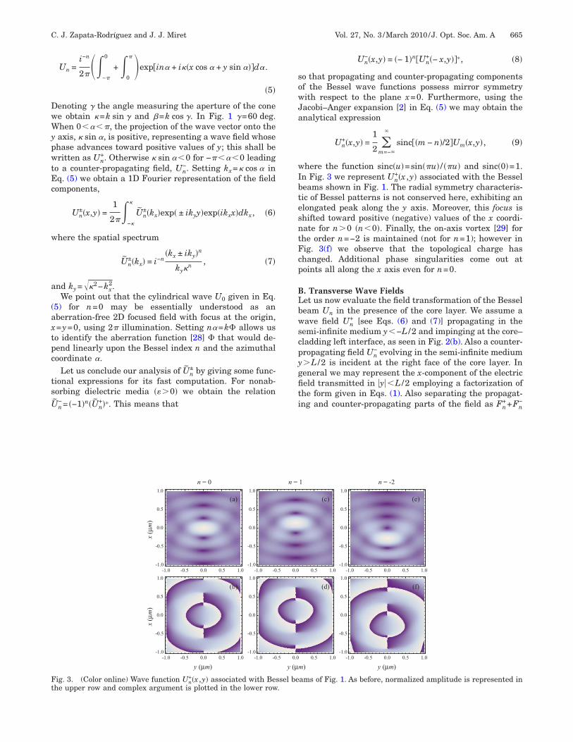
+�x ,y� associated with the Besseleams shown in Fig. 1. The radial symmetry characteris-ic of Bessel patterns is not conserved here, exhibiting anlongated peak along the y axis. Moreover, this focus ishifted toward positive (negative) values of the x coordi-ate for n�0 �n0�. Finally, the on-axis vortex [29] forhe order n=−2 is maintained (not for n=1); however inig. 3(f) we observe that the topological charge hashanged. Additional phase singularities come out atoints all along the x axis even for n=0.
. Transverse Wave Fieldset us now evaluate the field transformation of the Besseleam Un in the presence of the core layer. We assume aave field Un
+ [see Eqs. (6) and (7)] propagating in theemi-infinite medium y−L /2 and impinging at the core–ladding left interface, as seen in Fig. 2(b). Also a counter-ropagating field Un
− evolving in the semi-infinite medium�L /2 is incident at the right face of the core layer. Ineneral we may represent the x-component of the electriceld transmitted in �y�L /2 employing a factorization ofhe form given in Eqs. (1). Also separating the propagat-
+ −
ng and counter-propagating parts of the field as Fn+Fny (µm) y (µm) y (µm)
x(µm)
x(µm)
n = 0 n = 1 n = -2
(a) (c) (e)
(b) (d) (f)
-1.0 -0.5 0.0 0.5 1.0-1.0
-0.5
0.0
0.5
1.0
-1.0 -0.5 0.0 0.5 1.0-1.0
-0.5
0.0
0.5
1.0
-1.0 -0.5 0.0 0.5 1.0-1.0
-0.5
0.0
0.5
1.0
-1.0 -0.5 0.0 0.5 1.0-1.0
-0.5
0.0
0.5
1.0
-1.0 -0.5 0.0 0.5 1.0-1.0
-0.5
0.0
0.5
1.0
-1.0 -0.5 0.0 0.5 1.0-1.0
-0.5
0.0
0.5
1.0
ig. 3. (Color online) Wave function Un+�x ,y� associated with Bessel beams of Fig. 1. As before, normalized amplitude is represented in
he upper row and complex argument is plotted in the lower row.
wE=
Hwo
�cFfltt
sw
vrmiOcad
tts=s
w
Eatscs
cd(Aicttim
4LttdTc�ssf
itflatd
ttmgfpnaepta
666 J. Opt. Soc. Am. A/Vol. 27, No. 3 /March 2010 C. J. Zapata-Rodríguez and J. J. Miret
e may use the Fourier integral representation shown inq. (6), replacing ky by kc,y=�kc
2−�2−kx2, where kc
���c /c. Explicitly we write
Fn±�x,y� =
1
2��
−�
�
Fn±�kx�exp� ± ikc,yy�exp�ikxx�dkx.
�10�
ere kc,y=kc,y� + ikc,y� is in general a complex number,here kc,y� �0; also kc,y� �0 leading to either homogeneousr damped waves inside the slab.
Additionally, the fields Rn− (in y−L /2) and Rn
+ (in yL /2) flowing away from the core layer should be in-
luded for a complete description, schematically shown inig. 2(b). In core barriers, these fields account for re-ected waves from Un
+ and Un−, respectively. However, in
he limit →0 we would have Rn±=Un
± related to transmit-ed waves through the core medium. In general,
Rn±�x,y� =
1
2��
−�
�
Rn±�kx�exp� ± ikyy�exp�ikxx�dkx �11�
tand for a combination of reflected and transmittedaves as shown below.We point out that the condition �k disposes of a di-
erging behavior of Un± far off the core layer. These unidi-
ectional wave fields, on the other hand, lead to the for-ation of localized radiation modes. Such an optical feed
s necessary to obtain a real-valued propagation constant.therwise it gives rise to leaky modes [30] when � is a
omplex number, which might be understood as the in-bility to suppress the natural intensity decay induced byiffraction.In the following, the spatial spectra Fn
± and Rn± are es-
imated. Boundary conditions for the s-polarized waves athe core–cladding interfaces lead to the continuity of thecalar field Ex and its normal derivative �0
−1�Ex /�y at y±L /2. Therefore the propagation constant � is con-
erved in the layered media. Also we obtain
�Rn±
Fn± = �A B
C D � Un±
Un� , �12�
here
A =4kc,yky expi�kc,y − ky�L
�kc,y + ky�2 − �kc,y − ky�2 exp�2ikc,yL�, �13a�
B =2i�kc,y
2 − ky2�sin�kc,yL�expi�kc,y − ky�L
�kc,y + ky�2 − �kc,y − ky�2 exp�2ikc,yL�, �13b�
C =2ky�kc,y + ky�expi�kc,y − ky�L/2
�k + k �2 − �k − k �2 exp�2ik L�, �13c�
c,y y c,y y c,y
D =2ky�kc,y − ky�exp�ikc,yL�expi�kc,y − ky�L/2
�kc,y + ky�2 − �kc,y − ky�2 exp�2ikc,yL�.
�13d�
xcepting the phase factor exp�−ikyL�, the terms A�kx�nd B�kx� are simply the Airy formulas corresponding tohe transmittance and reflectance coefficients through thelab [31]. Thus, the matrix elements A and B quantify theontribution of reflected and transmitted wavelets to thecattered fields Rn
±.We confirm that Un
±= Fn±=Rn
± under perfect matchingonditions; note that =0 yields kc,y=ky. However, seriouseviations arise when �kc,y−ky�L�1 for which the phaseexponential) factor in the numerator of the coefficientsBCD given in Eqs. (13) oscillates (falls off) rapidly. This
nequality is approximately satisfied if � �L�2� /k2. Spe-ifically for both material and beam sizes of the order ofhe wavelength, L�� and ��k, a case that is analyzed inhe next section, it yields � ��1/�, so that the differencen refractive indices for the core and the cladding layers
ight not be excessively large.
. NUMERICAL SIMULATIONSet us first evaluate numerically the amplitude distribu-
ion of the wave function ex corresponding to Bessel exci-ations like those of Fig. 1 in a centered dielectric slab ofielectric constant with relative increment =10−2.herefore the source spectra Un
± are those of Eq. (7). Wehoose L=100 �m in order to hold the inequality � �L�sin ��� /� at �=0.6 �m and �=60 deg. In this case the
lab width is much larger than the spot size of the Besselource so that wave localization is expected at points farrom the surfaces.
The resultant wave function,
ex�x,y� = �Un
+�x,y� + Rn−�x,y�, if y − L/2;
Fn+�x,y� + Fn
−�x,y�, if �y� L/2;
Un−�x,y� + Rn
+�x,y�, if y � L/2;� �14�
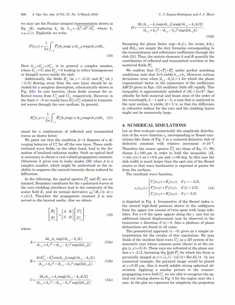
s depicted in Fig. 4. Irrespective of the Bessel index n,he central high-field patterns shown in the subfiguresrom the upper row consist of twin spots with large side-obes. For n=0 the spots appear along the y axis but andditional lateral displacement may be observed in theransverse x direction if �n��0. Also a plethora of phaseislocations are found in all cases.The geometrical approach ��→0� gives us a simple in-
erpretation for the results of this simulation: We mayhink of the incident focal wave Un
+ as a 2D system of ho-ocentric rays whose common point (focus) is at the ori-
in �x ,y�= �0,0�. These rays are refracted at the plane sur-ace y=−L /2, becoming the field Fn
+ for which the focus isaraxially imaged at y= ���c /�−1�L /2�Re� �L /4 . In ourumerical example, the paraxial image would be placedt y=0.25 �m. Also it would exhibit strong spherical ab-rration. Applying a similar picture to the counter-ropagating wave field Un
− we are able to recognize the op-ical ray tracing shown in Fig. 5 for the region near the zxis. In the plot we represent for simplicity the projection
otrcBlld
wtlEaw
ri
plfsr
wrcscfiHceslsiest
tpat=wtoctctomtlp
Ft
Fl(Sg
C. J. Zapata-Rodríguez and J. J. Miret Vol. 27, No. 3 /March 2010/J. Opt. Soc. Am. A 667
f ray traces onto the xy plane inside the lamellar dielec-ric structure. Our previous discussion supports the highay concentration that is produced around the dual opti-al axes �x ,y�= �0, ±0.25� �m. We may conclude thatessel excitations in the presence of the thin dielectric
ayer yield a pair of localized wave fields whose proximityeads to a linear interaction still conserving theiffraction-free characteristic of the originating beam.In order to analyze surface effects we reduce the slab
idth L to approaching a wavelength and, additionally,he wave impedance mismatching is increased. In theimit � �→ we obtain Fn
±=0 and Rn±=−exp�−ikyL�Un
� fromqs. (12) and (13). In this case, the core layer behaves liken infinite tunneling barrier prohibiting the transit of theave through itself. Thus each reflected field,
Rn±�x,y� = − Un
��x,− y ± L�, �15�
eproduces a mirror-symmetric version of its correspond-ng incident wave field in the cladding medium. Also the
y (µm)
x(µm)
x(µm)
n = 0
(a)
(b)
-1.0 -0.5 0.0 0.5 1.0-1.0
-0.5
0.0
0.5
1.0
-1.0 -0-1.0
-0.5
0.0
0.5
1.0
-1.0 -0-1.0
-0.5
0.0
0.5
1.0
-1.0 -0.5 0.0 0.5 1.0-1.0
-0.5
0.0
0.5
1.0
ig. 4. (Color online) Transverse distribution of Bessel-excited werial with relative dielectric constant =10−2. Again �ex� is plotted
-1.0 -0.5 0.0 0.5 1.0-1.0
-0.5
0.0
0.5
1.0
y (µm)
x(µm)
ig. 5. (Color online) Ray tracing representation of the Bessel-ike beams shown in Fig. 4. Dual parallel axes at y= ±0.25 �mand x=0) set the confinement region of the nondiffracting beam.pherical aberration drawing the envelope of the refracted raysives rise to a bilateral-symmetric caustic.
hase factor of argument −kyL in the spatial spectrumeads to a displacement L along the y axis of the originalocus. That is, the geometric focus of the wave field U± istigmatically imaged by means of R� at �x ,y�= �0, �L�,espectively.
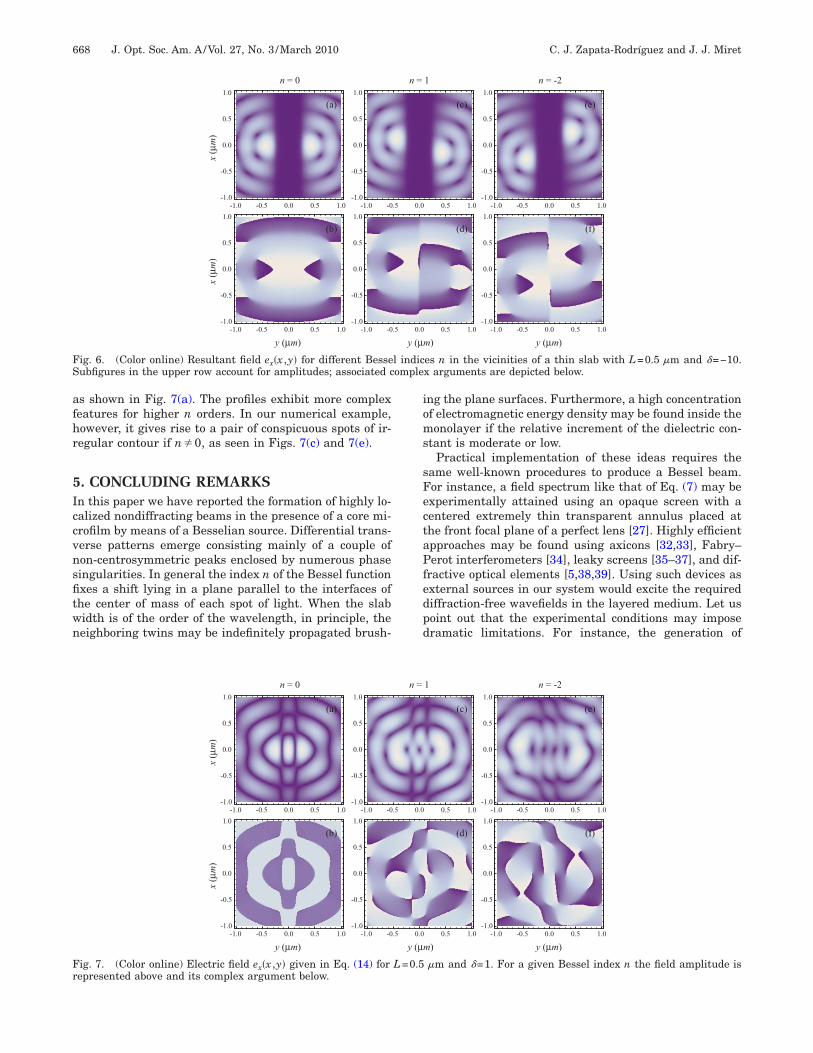
Fig. 6 shows the complex amplitude and phase of theave function ex�x ,y� given in Eq. (14) for material pa-
ameters L=0.5 �m and =−10. A bifocal 2D pattern islear in the amplitude figures following a previous discus-ion. Interestingly, the size of the twin spots is signifi-antly lower in the y direction than that of the sourceelds Un
±, and it is close to the width of the J0 pattern.owever, this superresolving effect is nearly lost if L in-
reases sufficiently. We may conclude that the interfer-nce of propagating and counter-propagating fields whosepectra approach Un
+ in y−L /2 and Un− in y�L /2 in the
imit � �→ yields a couple of intense superresolvingpots near the surfaces of the thin core film. This effect isndependent of the Bessel index n; however it drives a lat-ral shift along the x axis. Finally, one can see in Fig. 6 aet of phase singularities whose charge is independent ofhe index n from the Besselian source.
As seen in the amplitude distribution of Figs. 4 and 6,he Bessel index n induces a lateral shift of the twineaks in the presence of the thin film. However, this is notuniversal rule as shown in the following example. The
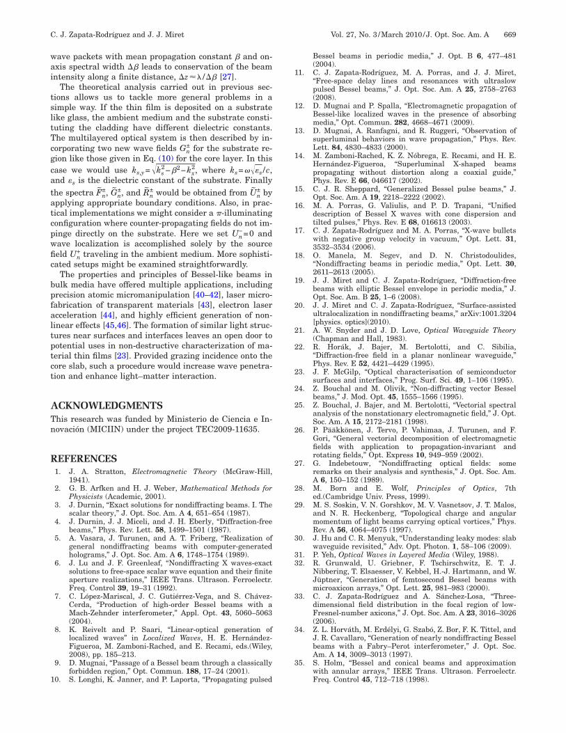
ransverse profile of the electric field ex�x ,y� for L0.5 �m and =1 is depicted in Fig. 7. In this case, theave clearly penetrates into the core slab, leading to a net
ransfer of energy from one side of the cladding to thether side. Then the transmitted field is coupled with theounter-propagating incident wave in order to regeneratehe Besselian pattern, which, however, shows a signifi-ant distortion and blurring. Inside the core film, theransmitted fields are superposed with scattered wavesriginating from multiple reflections on the surfaces. Theultiple-beam interference leads to a standing wave in
he xy plane with resonant peaks and nodes (phase singu-arities) mainly along the y axis. For instance, threeeaks form the shape of the diffraction-free beam if n=0,
m) y (µm)
1 n = -2
(c) (e)
(d) (f)
0.5 1.0 -1.0 -0.5 0.0 0.5 1.0-1.0
-0.5
0.0
0.5
1.0
-1.0 -0.5 0.0 0.5 1.0-1.0
-0.5
0.0
0.5
1.0
0.5 1.0
eld ex�x ,y� inside a thin slab of width L=100 �m made of a ma-upper row and its complex argument is shown in the lower row.
y (µ
n =
.5 0.0
.5 0.0
ave fiin the
afhr
5Iccvnsfitwn
ioms
sFectaPfedpd
Fr
FS omple
668 J. Opt. Soc. Am. A/Vol. 27, No. 3 /March 2010 C. J. Zapata-Rodríguez and J. J. Miret
s shown in Fig. 7(a). The profiles exhibit more complexeatures for higher n orders. In our numerical example,owever, it gives rise to a pair of conspicuous spots of ir-egular contour if n�0, as seen in Figs. 7(c) and 7(e).
. CONCLUDING REMARKSn this paper we have reported the formation of highly lo-alized nondiffracting beams in the presence of a core mi-rofilm by means of a Besselian source. Differential trans-erse patterns emerge consisting mainly of a couple ofon-centrosymmetric peaks enclosed by numerous phaseingularities. In general the index n of the Bessel functionxes a shift lying in a plane parallel to the interfaces ofhe center of mass of each spot of light. When the slabidth is of the order of the wavelength, in principle, theeighboring twins may be indefinitely propagated brush-
y (µm)
x(µm)
x(µm)
n = 0
(a)
(b)
-1.0 -0.5 0.0 0.5 1.0-1.0
-0.5
0.0
0.5
1.0
-1.0 -0-1.0
-0.5
0.0
0.5
1.0
-1.0 -0-1.0
-0.5
0.0
0.5
1.0
-1.0 -0.5 0.0 0.5 1.0-1.0
-0.5
0.0
0.5
1.0
ig. 6. (Color online) Resultant field ex�x ,y� for different Besseubfigures in the upper row account for amplitudes; associated c
ng the plane surfaces. Furthermore, a high concentrationf electromagnetic energy density may be found inside theonolayer if the relative increment of the dielectric con-
tant is moderate or low.Practical implementation of these ideas requires the
ame well-known procedures to produce a Bessel beam.or instance, a field spectrum like that of Eq. (7) may bexperimentally attained using an opaque screen with aentered extremely thin transparent annulus placed athe front focal plane of a perfect lens [27]. Highly efficientpproaches may be found using axicons [32,33], Fabry–erot interferometers [34], leaky screens [35–37], and dif-
ractive optical elements [5,38,39]. Using such devices asxternal sources in our system would excite the requirediffraction-free wavefields in the layered medium. Let usoint out that the experimental conditions may imposeramatic limitations. For instance, the generation of
m) y (µm)
1 n = -2
(c) (e)
(d) (f)
0.5 1.0 -1.0 -0.5 0.0 0.5 1.0-1.0
-0.5
0.0
0.5
1.0
-1.0 -0.5 0.0 0.5 1.0-1.0
-0.5
0.0
0.5
1.0
0.5 1.0
es n in the vicinities of a thin slab with L=0.5 �m and =−10.x arguments are depicted below.
y (µm) y (µm) y (µm)
x(µm)
x(µm)
n = 0 n = 1 n = -2
(a) (c) (e)
(b) (d) (f)
-1.0 -0.5 0.0 0.5 1.0-1.0
-0.5
0.0
0.5
1.0
-1.0 -0.5 0.0 0.5 1.0-1.0
-0.5
0.0
0.5
1.0
-1.0 -0.5 0.0 0.5 1.0-1.0
-0.5
0.0
0.5
1.0
-1.0 -0.5 0.0 0.5 1.0-1.0
-0.5
0.0
0.5
1.0
-1.0 -0.5 0.0 0.5 1.0-1.0
-0.5
0.0
0.5
1.0
-1.0 -0.5 0.0 0.5 1.0-1.0
-0.5
0.0
0.5
1.0
ig. 7. (Color online) Electric field ex�x ,y� given in Eq. (14) for L=0.5 �m and =1. For a given Bessel index n the field amplitude isepresented above and its complex argument below.
y (µ
n =
.5 0.0
.5 0.0
l indic
wai
tsltTcgcatatcpwfic
bpfaltptct
ATn
R
1
1
1
1
1
1
1
1
1
1
2
2
2
2
2
2
2
2
2
2
3
33
3
3
3
C. J. Zapata-Rodríguez and J. J. Miret Vol. 27, No. 3 /March 2010/J. Opt. Soc. Am. A 669
ave packets with mean propagation constant � and on-xis spectral width �� leads to conservation of the beamntensity along a finite distance, �z�� /�� [27].
The theoretical analysis carried out in previous sec-ions allows us to tackle more general problems in aimple way. If the thin film is deposited on a substrateike glass, the ambient medium and the substrate consti-uting the cladding have different dielectric constants.he multilayered optical system is then described by in-orporating two new wave fields Gn
± for the substrate re-ion like those given in Eq. (10) for the core layer. In thisase we would use ks,y=�ks
2−�2−kx2, where ks=���s /c,
nd �s is the dielectric constant of the substrate. Finallyhe spectra Fn
±, Gn±, and Rn
± would be obtained from Un± by
pplying appropriate boundary conditions. Also, in prac-ical implementations we might consider a �-illuminatingonfiguration where counter-propagating fields do not im-inge directly on the substrate. Here we set Un
−=0 andave localization is accomplished solely by the sourceeld Un
+ traveling in the ambient medium. More sophisti-ated setups might be examined straightforwardly.
The properties and principles of Bessel-like beams inulk media have offered multiple applications, includingrecision atomic micromanipulation [40–42], laser micro-abrication of transparent materials [43], electron lasercceleration [44], and highly efficient generation of non-inear effects [45,46]. The formation of similar light struc-ures near surfaces and interfaces leaves an open door tootential uses in non-destructive characterization of ma-erial thin films [23]. Provided grazing incidence onto theore slab, such a procedure would increase wave penetra-ion and enhance light–matter interaction.
CKNOWLEDGMENTShis research was funded by Ministerio de Ciencia e In-ovación (MICIIN) under the project TEC2009-11635.
EFERENCES1. J. A. Stratton, Electromagnetic Theory (McGraw-Hill,
1941).2. G. B. Arfken and H. J. Weber, Mathematical Methods for
Physicists (Academic, 2001).3. J. Durnin, “Exact solutions for nondiffracting beams. I. The
scalar theory,” J. Opt. Soc. Am. A 4, 651–654 (1987).4. J. Durnin, J. J. Miceli, and J. H. Eberly, “Diffraction-free
beams,” Phys. Rev. Lett. 58, 1499–1501 (1987).5. A. Vasara, J. Turunen, and A. T. Friberg, “Realization of
general nondiffracting beams with computer-generatedholograms,” J. Opt. Soc. Am. A 6, 1748–1754 (1989).
6. J. Lu and J. F. Greenleaf, “Nondiffracting X waves-exactsolutions to free-space scalar wave equation and their finiteaperture realizations,” IEEE Trans. Ultrason. Ferroelectr.Freq. Control 39, 19–31 (1992).
7. C. López-Mariscal, J. C. Gutiérrez-Vega, and S. Chávez-Cerda, “Production of high-order Bessel beams with aMach-Zehnder interferometer,” Appl. Opt. 43, 5060–5063(2004).
8. K. Reivelt and P. Saari, “Linear-optical generation oflocalized waves” in Localized Waves, H. E. Hernández-Figueroa, M. Zamboni-Rached, and E. Recami, eds.(Wiley,2008), pp. 185–213.
9. D. Mugnai, “Passage of a Bessel beam through a classicallyforbidden region,” Opt. Commun. 188, 17–24 (2001).
0. S. Longhi, K. Janner, and P. Laporta, “Propagating pulsed
Bessel beams in periodic media,” J. Opt. B 6, 477–481(2004).
1. C. J. Zapata-Rodríguez, M. A. Porras, and J. J. Miret,“Free-space delay lines and resonances with ultraslowpulsed Bessel beams,” J. Opt. Soc. Am. A 25, 2758–2763(2008).
2. D. Mugnai and P. Spalla, “Electromagnetic propagation ofBessel-like localized waves in the presence of absorbingmedia,” Opt. Commun. 282, 4668–4671 (2009).
3. D. Mugnai, A. Ranfagni, and R. Ruggeri, “Observation ofsuperluminal behaviors in wave propagation,” Phys. Rev.Lett. 84, 4830–4833 (2000).
4. M. Zamboni-Rached, K. Z. Nóbrega, E. Recami, and H. E.Hernández-Figueroa, “Superluminal X-shaped beamspropagating without distortion along a coaxial guide,”Phys. Rev. E 66, 046617 (2002).
5. C. J. R. Sheppard, “Generalized Bessel pulse beams,” J.Opt. Soc. Am. A 19, 2218–2222 (2002).
6. M. A. Porras, G. Valiulis, and P. D. Trapani, “Unifieddescription of Bessel X waves with cone dispersion andtilted pulses,” Phys. Rev. E 68, 016613 (2003).
7. C. J. Zapata-Rodríguez and M. A. Porras, “X-wave bulletswith negative group velocity in vacuum,” Opt. Lett. 31,3532–3534 (2006).
8. O. Manela, M. Segev, and D. N. Christodoulides,“Nondiffracting beams in periodic media,” Opt. Lett. 30,2611–2613 (2005).
9. J. J. Miret and C. J. Zapata-Rodríguez, “Diffraction-freebeams with elliptic Bessel envelope in periodic media,” J.Opt. Soc. Am. B 25, 1–6 (2008).
0. J. J. Miret and C. J. Zapata-Rodríguez, “Surface-assistedultralocalization in nondiffracting beams,” arXiv:1001.3204[physics. optics](2010).
1. A. W. Snyder and J. D. Love, Optical Waveguide Theory(Chapman and Hall, 1983).
2. R. Horák, J. Bajer, M. Bertolotti, and C. Sibilia,“Diffraction-free field in a planar nonlinear waveguide,”Phys. Rev. E 52, 4421–4429 (1995).
3. J. F. McGilp, “Optical characterisation of semiconductorsurfaces and interfaces,” Prog. Surf. Sci. 49, 1–106 (1995).
4. Z. Bouchal and M. Olivik, “Non-diffracting vector Besselbeams,” J. Mod. Opt. 45, 1555–1566 (1995).
5. Z. Bouchal, J. Bajer, and M. Bertolotti, “Vectorial spectralanalysis of the nonstationary electromagnetic field,” J. Opt.Soc. Am. A 15, 2172–2181 (1998).
6. P. Pääkkönen, J. Tervo, P. Vahimaa, J. Turunen, and F.Gori, “General vectorial decomposition of electromagneticfields with application to propagation-invariant androtating fields,” Opt. Express 10, 949–959 (2002).
7. G. Indebetouw, “Nondiffracting optical fields: someremarks on their analysis and synthesis,” J. Opt. Soc. Am.A 6, 150–152 (1989).
8. M. Born and E. Wolf, Principles of Optics, 7thed.(Cambridge Univ. Press, 1999).
9. M. S. Soskin, V. N. Gorshkov, M. V. Vasnetsov, J. T. Malos,and N. R. Heckenberg, “Topological charge and angularmomentum of light beams carrying optical vortices,” Phys.Rev. A 56, 4064–4075 (1997).
0. J. Hu and C. R. Menyuk, “Understanding leaky modes: slabwaveguide revisited,” Adv. Opt. Photon. 1, 58–106 (2009).
1. P. Yeh, Optical Waves in Layered Media (Wiley, 1988).2. R. Grunwald, U. Griebner, F. Tschirschwitz, E. T. J.
Nibbering, T. Elsaesser, V. Kebbel, H.-J. Hartmann, and W.Jüptner, “Generation of femtosecond Bessel beams withmicroaxicon arrays,” Opt. Lett. 25, 981–983 (2000).
3. C. J. Zapata-Rodríguez and A. Sánchez-Losa, “Three-dimensional field distribution in the focal region of low-Fresnel-number axicons,” J. Opt. Soc. Am. A 23, 3016–3026(2006).
4. Z. L. Horváth, M. Erdélyi, G. Szabó, Z. Bor, F. K. Tittel, andJ. R. Cavallaro, “Generation of nearly nondiffracting Besselbeams with a Fabry–Perot interferometer,” J. Opt. Soc.Am. A 14, 3009–3013 (1997).
5. S. Holm, “Bessel and conical beams and approximationwith annular arrays,” IEEE Trans. Ultrason. Ferroelectr.Freq. Control 45, 712–718 (1998).
3
3
3
3
4
4
4
4
4
4
4
670 J. Opt. Soc. Am. A/Vol. 27, No. 3 /March 2010 C. J. Zapata-Rodríguez and J. J. Miret
6. K. Reivelt and P. Saari, “Optically realizable localized wavesolutions of the homogeneous scalar wave equation,” Phys.Rev. E 65, 046622 (2002).
7. K. Reivelt and P. Saari, “Experimental demonstration ofrealizability of optical focus wave modes,” Phys. Rev. E 66,056611 (2002).
8. J. Amako, D. Sawaki, and E. Fujii, “Microstructuringtransparent materials by use of nondiffracting ultrashortpulse beams generated by diffractive optics,” J. Opt. Soc.Am. B 20, 2562–2568 (2003).
9. Z. Li, K. B. Alici, H. Caglayan, and E. Ozbay, “Generationof an axially asymmetric Bessel-like beam from a metallicsubwavelength aperture,” Phys. Rev. Lett. 102, 143901(2009).
0. J. Arlt and M. J. Padgett, “Generation of a beam with adark focus surrounded by regions of higher intensity: theoptical bottle beam,” Opt. Lett. 25, 191–193 (2000).
1. J. Arlt, T. Hitomi, and K. Dholakia, “Atom guiding alongLaguerre-Gaussian and Bessel light beams,” Appl. Phys. B71, 549––554 (2000).
2. D. G. Grier, “A revolution in optical manipulation,” Nature424, 810–816 (2003).
3. Y. Matsuoka, Y. Kizuka, and T. Inoue, “The characteristicsof laser micro drilling using a Bessel beam,” Appl. Phys. A84, 423–430 (2006).
4. B. Hafizi, E. Esarey, and P. Sprangle, “Laser-drivenacceleration with Bessel beams,” Phys. Rev. E 55,3539–3545 (1997).
5. T. Wulle and S. Herminghaus, “Nonlinear optics of Besselbeams,” Phys. Rev. Lett. 70, 1401–1404 (1993).
6. M. A. Porras, A. Parola, D. Faccio, A. Dubietis, and P. D.Trapani, “Nonlinear unbalanced Bessel beams: Stationaryconical waves supported by nonlinear losses,” Phys. Rev.Lett. 93, 153902 (2004).