Embed Size (px)
Citation preview

User Manual
Digi-Sense® TC9500 Advanced
Multiparameter Temperature Controller
with Thermocouple, Thermistor, and RTD Inputs
Models 89800-03 and 89800-04
THE STANDARD IN PRECISION MEASUREMENT

2
Table of Contents
Introduction .......................................................................................................... 3
Unpacking ............................................................................................................ 3
Controller Description—Front Panel ..................................................................... 4
Controller Description—Back Panel ...................................................................... 5
Controller Description—Active Display Screen ..................................................... 6
Setup and Operation ........................................................................................... 7
Initial Setup ................................................................................................. 7
Basic Operation Setup................................................................................. 7
Auto Tune Setup .......................................................................................... 7
PID Control Mode Setup (Default Mode) ......................................................... 8–15
ON/OFF Control Mode Setup ........................................................................ 16–22
Ramp & Soak / Ramp Rate Control Mode Setup ........................................... 23–30
Data Acquisition Software .............................................................................. 31–33
Safety ................................................................................................................. 34
Specifications for Controller Models .............................................................. 35–36
Specifications for Sensor Inputs ........................................................................ 37
Screen Flow Charts ....................................................................................... 38–39
General Setup Flow Chart ........................................................................ 38
Advanced Menu Setup Flow Chart ........................................................... 39
RTD Wiring Instructions ..................................................................................... 40
Ferrite Clip Installation ........................................................................................ 40
Alternative Power Cords—for Various Countries ............................................... 41
Output Cord Adapters—for Various Countries ................................................... 42
Approvals ........................................................................................................... 43
Maintenance ....................................................................................................... 44
3
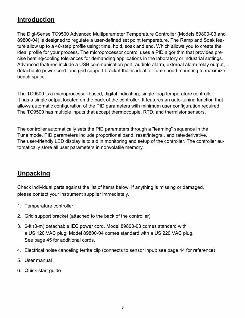
Introduction
The Digi-Sense TC9500 Advanced Multiparameter Temperature Controller (Models 89800-03 and
89800-04) is designed to regulate a user-defined set point temperature. The Ramp and Soak fea-
ture allow up to a 40-step profile using; time, hold, soak and end. Which allows you to create the
ideal profile for your process. The microprocessor control uses a PID algorithm that provides pre-
cise heating/cooling tolerances for demanding applications in the laboratory or industrial settings.
Advanced features include a USB communication port, audible alarm, external alarm relay output,
detachable power cord. and grid support bracket that is ideal for fume hood mounting to maximize
bench space.
The TC9500 is a microprocessor-based, digital indicating, single-loop temperature controller.
It has a single output located on the back of the controller. It features an auto-tuning function that
allows automatic configuration of the PID parameters with minimum user configuration required.
The TC9500 has multiple inputs that accept thermocouple, RTD, and thermistor sensors.
The controller automatically sets the PID parameters through a "learning" sequence in the
Tune mode. PID parameters include proportional band, reset/integral, and rate/derivative.
The user-friendly LED display is to aid in monitoring and setup of the controller. The controller au-
tomatically store all user parameters in nonvolatile memory.
Unpacking Check individual parts against the list of items below. If anything is missing or damaged,
please contact your instrument supplier immediately.
1. Temperature controller
2. Grid support bracket (attached to the back of the controller)
3. 6-ft (3-m) detachable IEC power cord. Model 89800-03 comes standard with
a US 120 VAC plug; Model 89800-04 comes standard with a US 220 VAC plug.
See page 45 for additional cords.
4. Electrical noise canceling ferrite clip (connects to sensor input; see page 44 for reference)
5. User manual
6. Quick-start guide

4
Controller Description - Front Panel
1. RUN/STOP Button
Pressing RUN/STOP once will start the control process if the Temperature Controller is stopped, or stop the control process if the
Temperature Controller is running. If the Temperature Controller is running, “Heat” and “Cool” on-screen indicators will illuminate
appropriately in the “Alarm/Action Display”.
2. TUNE Button
Pressing TUNE once will start the AUTO TUNE cycle. AUTO TUNING must be enabled in the setup mode for this key to function.
(See page 14, Screen 16)
3. ALARM Button
In an ALARM situation, the screen will display either “WARNING” or “ERROR” with the corresponding message. A “WARNING”
will not stop the control process. An “ERROR” will stop the control process.
A. MANUAL RESET mode: Pressing ALARM once will silence the audible alarm and clear the on-screen alarm message. If the alarm situation is
still presents the “Alarm/Action Display” will remain illuminated. The alarm and on-screen message will not clear automatically, even if the system
is no longer in an alarm situation.
B. AUTO RESET mode: Pressing ALARM once will silence the audible alarm and clear the on-screen alarm message. If the alarm situation is
still present, the “Alarm/Action Display” will remain illuminated. If the system leaves an alarm situation, the system will automatically silence the
alarm and clear the on-screen alarm message.
4. SELECT Button
Pressing SELECT once will cycle through user-configurable control set points. All user-configurable set points will be underlined
with a greyed out line. The selected Set Point will be underlined. Change the set point with the UP and DOWN arrow buttons.
5. MENU Button
The MENU button provides access to all user-configurable setup parameters of the controller. Pressing this key once will scroll
through parameter options. Pressing and holding this key will exit to the home screen, saving any changes made up to that point.
6. UP, DOWN, LEFT Arrow Buttons
The UP and DOWN arrow buttons will increase or decrease the value of the set point selected (underlined). Pressing the UP or
DOWN arrow keys will increase or decrease numerical entries by the least significant digit. The rate of acceleration will increase as
shown in the table below, starting from the least significant digit. Pressing and holding the UP or DOWN arrow key will increase or
decrease text entries without an acceleration factor. The LEFT arrow button moves backwards through the General and Advanced
Setup Menus. To exit to the main screen from either menu, press and hold the MENU button.
7. HEAT, COOL, AND TUNE Indicators
When any of these modes are active they will have a block indicator on the display showing they are active. Example: When the
control is in the heat mode and it is applying power to the heater output there will be an indicator block on the display to show the
heater output is active.
Numbers… Increase/Decrease by…
0.0 – 0.9 0.1
0 – 9 1
10 – 100 10
100 + 50 Table 1. Acceleration Factor Table

5
Controller Description — Back Panel
1. IEC power cord connection (see page 45 for additional cords)
2. Heater/cooler output (see pages 46-47 for optional cord adapters dependent on country)
3. Power switch
4. Grid support bracket
5. External alarm output
6. USB port
7. Thermistor input: accepts type 400 and 700 with Digi-Sense phone plug connector
8. Thermocouple input: accepts type J, K, N, R, S, T, B, and E with mini-connector
9. RTD input: accepts type Alpha 0.003850, Alpha 0.003850 manufactured with MgO and Alpha
0.003916 with ANSI 3 blade connector. (RTD probes with ANSI connectors purchased from
Cole-Parmer or Davis Instruments before May of 2013 will need the wiring in the probe connect-
or modified. See page 44 for wiring instructions.)
10. RTD input: accepts Digi-Sense 3-pin round connector
11. Fuse
IEC 60320 C19, 230 VOLT
(Image shows this receptacle)
Model 89800-04
5-15R ,115 VOLT
Heater/Cooler output based on model
Model 89800-03

6
Controller Description — Active Display Screen

7
Setup and Operation Initial Setup
Install controller in a safe operating area.
Plug the heating or cooling device (sold separately) into the output connector, located on the
back of the controller.
Connect input sensor into the proper connection input on the back of the controller.
Place the ferrite clip over lead wire of sensor (see page 44 for reference picture of installation).
Connect external alarm output to the controller (optional).
Connect USB cable to the USB connector, located on the back of the controller (optional).
Plug supplied AC cord into the IEC input connector, located on the back of the controller.
Basic Operation Setup
Turn power switch ON, located on the back of controller.
Follow the instructions on the “welcome” screen.
- Press SELECT key to read a brief description of each key on the front of controller.
- Press the MENU key to skip the instructions and enter into the main operation screen.
Press the SELECT key to make a user-editable field active. A line will appear under the field
when the field is active for editing.
Use the UP/DOWN arrow keys to adjust the value that is active in a user-editable field.
Enter the user-configurable setup by pressing the MENU key from the system status screen.
Use the MENU key to advance through each menu setting.
Hold UP and press DOWN arrow keys to jump directly to Output Power adjustment screen.
Depending on process operation, follow the directions to set up the controller for the proper
operation of your process:
- PID (factory default) on pages 8-15
- ON/OFF on pages 16-22
- Ramp & Soak on pages 23-30
All changed settings will be retained in memory when returning to the System Status screen.
Use the screen flow charts (see pages 42-43) to have a visual of the controls menu layout.
Auto Tune Operation
Set up your process as noted in the initial setup.
Verify that the Auto Tune feature is enabled in the menu settings.
From the main operation screen set the set point temperature.
Press the TUNE button and the indicators showing Heat and Tune will be illuminated on display.
The Set Point value can not be altered after the Tune process has started. The value is locked
until the Tune process is complete or aborted by the user.
Please note that the controller will tune at 90% of the set point. Don’t be alarmed if the controller
does not reach your entered set point in the tune mode.
Stopping the Tune operation prior to it finishing will cause the PID settings to be returned to
factory default values.
PID values will be saved in nonvolatile memory.

8
PID Control Mode Setup: (FACTORY DEFAULT MODE)
Screen # 1 - Selecting Sensor Type
Press the MENU key one time to select sensor input type.
Use UP/DOWN arrow keys to change sensor type.
Press MENU key when complete.
Screen # 2 - Selecting Sensor Type
If Thermocouple is selected on screen # 1:
Use the UP/DOWN arrow keys to select the desired
thermocouple type: J, K, N, R, S, T, B, or E.
Press MENU key to advance to screen #3 after selection has been made.
If Thermistor is selected on screen # 1:
Use UP/DOWN arrow keys to select the desired
thermistor type: 400 or 700.
Press MENU key to advance to screen #3 after selection has been made.
If RTD is selected on screen # 1:
Use UP/DOWN arrow keys to select the desired
RTD type: Alpha 003850, 003850 w/ MgO, or 003916.
Press MENU key to advance to screen #3 after selection has been made.
Screen # 3 - Selecting Temperature Scale
Use the UP/DOWN keys to select the desired temperature
scale: Celsius °C, Fahrenheit °F, Kelvin K, Reaumur °Ré,
or Rankine °Ra.
Press MENU key to advance to screen # 4 after selection has been made.

9
PID Control Mode Setup:
Screen # 4 - Selecting Alarm Setting
Use the UP/DOWN arrow keys to change between
Auto Reset, Manual Reset and Off.
Press MENU key to advance to next screen.
- If Auto or Manual is selected, the controller will advance to screen # 5.
- If selection is OFF, the controller will advance to screen # 9.
Screen # 5 - Selecting Alarm Mode
Use the UP / DOWN arrow keys to select alarm mode.
Selectable alarm modes:
- Process High: The alarm will be activated if the temperature rises above the
user set alarm value.
- Process Low: The alarm will be activated if the temperature goes below the
user set alarm value.
- Process High/Low: The alarm will be activated if the temperature goes above or below
the high and low temperature levels set by user.
- Deviation High: Alarm activation point that changes with the change of the process set
point. Example: The user sets deviation high alarm at 30°C and has a process set point of 100°
C.
If the temperature reaches 130°C, the alarm will be activated. The user changes process set
point to 60°C. If process temperature reaches 90°C, the alarm will be activated.
- Deviation Low: Alarm activation point that changes with the change of the process set
point. Example: The user sets the deviation low alarm at 30°C and the process set point is 100°
C.
If the process temperature is 70°C or less, the alarm will be activated. If the process set point
temperature is set at 70°C, then if the process temperature is 40°C or less, it will activate the
alarm.
- Deviation High/Low: Same as Deviation High and Deviation Low alarms. It has the
capability of having an alarm activate when the set point temperature goes above or
below a set point temperature.
- Deviation Band: Allows the user to set the alarm to be activated within a specified
temperature range.
Press the MENU key to advance to screen # 6 after selecting alarm mode.

10
PID Control Mode Setup:
Screen # 6 - Setting Alarm Mode Variables
This screen reflects the variable settings for the selected alarm mode from screen # 5.
-Set Point—Process High
- Press the UP/DOWN arrow keys to adjust the
temperature value.
- When complete, press MENU key to advance to screen # 7.
-Set Point—Process Low
- Press the UP/DOWN arrow keys to adjust the
temperature value.
- When complete, press MENU key to advance to screen # 7.
-Set Point—Process High/Low
- Press the UP/DOWN arrow keys to adjust the
temperature value.
- Press the SELECT key to toggle between High and Low.
There will be a line below the active field.
- When complete, press MENU key to advance to screen # 7.
-Set Point—Deviation High
- Press the UP/DOWN arrow keys to adjust the
temperature value.
- When complete, press MENU key to advance to screen # 7.
-Set Point—Deviation Low
- Press the UP/DOWN arrow keys to adjust the
temperature value.
- When complete, press MENU key to advance to screen # 7.

11
PID Control Mode Setup:
-Set Point—Deviation High/Low
- Press the UP/DOWN arrow keys to adjust the
temperature value.
- Press the SELECT key to toggle between the High and Low.
There will be a line below the active field.
- When complete, press MENU key to advance to screen # 7.
-Set Point—Deviation Band
- Press the UP/DOWN arrow keys to adjust the
temperature value.
- When complete, press MENU key to advance to screen # 7.
Screen # 7 - Setting Hysteresis Alarm
Use the UP/DOWN arrow keys to adjust value.
The user-defined value when the alarm will exit an alarm
condition. Example: User has a Process High alarm pro-
grammed with a value of 150°C
and has set the Alarm Hysteresis of 1°C. The alarm has been activated after the temperature
reached 160°C. When temperature reaches 149°C, the alarm condition will not be active.
When complete, press MENU key to advance to screen # 8.
Screen # 8 - Setting Audible Alarm
Use UP/DOWN arrow keys to change value to either
ON audible alarm or OFF audible alarm.
When complete, press MENU key to advance to screen # 9.

12
PID Control Mode Setup:
Screen # 9 - Advanced Menu Gateway
Use the UP/DOWN arrow keys to change selection to ENTER.
When complete, press MENU key to advance to screen # 10.
The following screens are in the advance portion of the
setup menu:
Screen # 10 - Calibration Gateway
Screen will default to SKIP Calibration Setup.
WARNING: Do not enter the calibration gateway unless
you have the proper calibration equipment to calibrate the sensor inputs associated with
this controller. Changing calibration settings in the controller can cause errors in sensor
temperature readings and operation of the control. For instructions on how to use the
calibration functions, contact your instrument supplier.
With SKIP selected, press the MENU key to advance to screen # 11.
Screen # 11 - Global Sensor Offset Calibration
Use the UP/DOWN arrow keys to change the offset value.
The use of another temperature device is required to
determine the correct offset needed.
Adjusting this value is offsetting the sensor input temperature being displayed.
When complete, press MENU key to advance to screen # 12.
Screen # 10 - Calibration Gateway
Screen # 11 - Global Sensor Offset
Screen # 12 - Over Temperature Stop
Screen # 13 - Loop Break Stop
Screen # 14 - Control Action
Screen # 15 - Control Mode
Screen # 16 - Auto Tune
Screen # 17 - Proportional Gain Setup
Screen # 18 - Integral Gain Setup
Screen # 19 - Derivative Rate Gain Setup
Screen # 20 - Power Rate Control
Screen # 21 - Run Time
Screen # 22 - Power Failure Control

13
PID Control Mode Setup:
Screen # 12 - Over Temperature Stop
Use UP/DOWN arrow keys to change the value.
When sensor temperature goes above this value, the output
device will be turned off.
When complete, press MENU key to advance to screen # 13.
Screen # 13 - Loop Break Stop
Default value is ENABLED. Use UP/DOWN arrow keys to
change the value.
Loop Break Stop is a feature that will stop the process output
while the controller is in the run mode. If the controller senses
there is no change in temperature in a user set amount of time, the output will be turned off and
error message will be displayed on the screen along with an audible alarm.
Set to DISABLED if this function is not required.
When complete, press MENU key to advance to screen # 14.
Screen # 14 - Control Action
Use UP/DOWN arrow keys to change the value.
Set for the process that is being performed: Heat or Cool
When complete, press MENU key to advance to screen # 15.
Screen # 15 - Control Mode
Use UP/DOWN arrow keys to change the value.
Default value is PID mode. (If different, select PID mode)
When complete, press MENU key to advance to screen # 16.

14
PID Control Mode Setup:
Screen # 16 - Auto Tune
Default value is ENABLED. Use UP/DOWN arrow keys
to toggle between ENABLED and DISABLED.
Select ENABLED to use the Tune key on the front panel to activate the Auto Tune function.
This function needs to remain ENABLED until the controller has been properly tuned to the
user’s particular application.
NOTE: the control auto tunes to 90% of the set point.
When complete, press MENU key to advance to screen # 17.
Screen # 17 - Proportional Gain Setup
Use UP/DOWN arrow keys to change the value.
WARNING: Do not change these values unless you have
experience in manual setup of PID (Proportional, Integral, and Derivative) of this controller.
These values are derived from running the auto tune function. Altering the value after auto tune
has been completed will affect the performance of the system.
When complete, press MENU key to advance to screen # 18.
Screen # 18 - Integral Gain Setup
Use UP/DOWN arrow keys to change the value.
WARNING: Do not change these values unless you have
experience in manual setup of PID (Proportional, Integral,
and Derivative) of this controller. These values are derived from running the auto tune function.
Altering the values after auto tune has been completed will affect the performance of the system.
When complete, press MENU key to advance to screen # 19.

15
PID Control Mode Setup:
Screen # 19 - Derivative Rate Gain Setup
Use UP/DOWN arrow keys to change the value.
WARNING: Do not change these values unless you have
experience in manual setup of PID (Proportional, Integral, and Derivative) of this controller.
These values are derived from running the auto tune function. Altering the value after auto tune
has been completed will affect the performance of the system.
When complete, press MENU key to advance to screen # 20.
Screen # 20 - Power Output Control
Use UP/DOWN arrow keys to change the value.
Default value is 100 percent.
This feature allows the user to reduce the output power to the output heating device—useful in
applications were temperature overshoot is occurring after auto tune has been completed.
Experimenting with this value will be necessary because every process setup is different.
When complete, press MENU key to advance to screen # 21.
Screen # 21 - Run Time
Use UP/DOWN arrow keys to change the value.
Use SELECT key to toggle between the HR and MIN fields.
Run Time is a safety feature while the control is in the ON/OFF or PID mode. The user can set a
timer to have the output turned OFF if the time expires.
When complete, press MENU key to advance to screen # 22.
Screen # 22 - Power Failure Control
Use UP/DOWN arrow keys to change the value.
Default value is STOP:
STOP — If the controller loses power while in the run mode, it will not resume the process
once the power has been restored.
RESUME — If the controller loses power while in the run mode, it will resume the operating
process once the power has been restored.
When complete, press MENU key to advance to screen # 23.
Screen # 23 - Advanced Menu Exit

16
ON/OFF Control Mode Setup:
Screen # 1 - Selecting Sensor Type
Press the MENU key one time to select sensor input type.
Use UP/DOWN arrow keys to change sensor type.
When complete, press MENU key to advance to next screen.
Screen # 2 - Selecting Sensor Type
If Thermocouple is selected on screen # 1:
Use the UP/DOWN arrow keys to select the desired
thermocouple type: J, K, N, R, S, T, B, or E.
Press MENU key to advance to screen #3 after selection has been made.
If Thermistor is selected on screen # 1:
Use UP/DOWN arrow keys to select the desired
thermistor type: 400 or 700.
Press MENU key to advance to screen #3 after selection has been made.
If RTD is selected on screen # 1:
Use UP/DOWN arrow keys to select the desired
RTD type: Alpha 003850, 003850 w/ MgO, or 003916.
Press MENU key to advance to screen #3 after selection has been made.
Screen # 3 - Selecting Temperature Scale
Use the UP/DOWN keys to select the desired temperature
scale: Celsius °C, Fahrenheit °F, Kelvin K, Reaumur °Ré,
or Rankine °Ra.
Press MENU key to advance to screen # 4 after selection has been made.

17
ON/OFF Control Mode Setup:
Screen # 4 - Selecting Alarm Setting
Use the UP/DOWN arrow keys to change between
Auto Reset, Manual Reset ,and Off.
Press MENU key to advance to next screen:
- If Auto or Manual is selected, the controller will advance to screen # 5.
- If selection is OFF, the controller will advance to screen # 9.
Screen # 5 - Selecting Alarm Mode
Use the UP/DOWN arrow keys to select alarm mode.
Selectable alarm modes:
- Process High: The alarm will be activated if the
temperature rises above the user set alarm value.
- Process Low: The alarm will be activated if the temperature goes below the
user set alarm value.
- Process High/Low: The alarm will be activated if the temperature goes above or below
the high and low temperature levels set by user.
- Deviation High: Alarm activation point that changes with the change of the process
set point. Example: The user sets deviation high alarm at 30°C and has a process set point of
100°C. If the temperature reaches 130°C, the alarm will be activated. The user changes
process set point to 60°C. If process temperature reaches 90°C, the alarm will be activated.
- Deviation Low: Alarm activation point that changes with the change of the process
set point. Example: User sets the deviation low alarm 30°C and the process set point is 100°C.
If the process temperature is 70°C or less, the alarm will be activated. If the process set point
temperature is set at 70°C, then if the process temperature is 40°C or less, it will activate the
alarm.
- Deviation High/Low: Same as Deviation High and Deviation Low alarms. It has the
capability of having an alarm activate when the set point temperature goes above or
below a set point temperature.
- Deviation Band: Allows the user to set the alarm to be activated within a specified
temperature range.
Press the MENU key to advance to screen # 6 after selecting alarm mode.

18
ON/OFF Control Mode Setup:
Screen # 6 - Setting Alarm Mode Variables
This screen reflects the variable settings for the selected alarm mode from screen # 5.
-Set Point—Process High
- Use UP/DOWN arrow keys to adjust the temperature value.
- When complete, press MENU key to advance to screen # 7.
- Set Point—Process Low
- Use UP/DOWN arrow keys to adjust the temperature value.
- When complete, press MENU key to advance to screen # 7.
- Set Point—Process High/Low
- Use UP/DOWN arrow keys to adjust the temperature value.
- Press the SELECT key to toggle between High and Low.
There will be a line below the active field.
- When complete, press MENU key to advance to screen # 7.
- Set Point—Deviation High
- Use UP/DOWN arrow keys to adjust the temperature value.
- When complete, press MENU key to advance to screen # 7.
- Set Point—Deviation Low
- Use UP/DOWN arrow keys to adjust the temperature value.
- When complete, press MENU key to advance to screen # 7.

19
ON/OFF Control Mode Setup:
-Set Point—Deviation High/Low
- Use UP/DOWN arrow keys to adjust the temperature value.
- Press the SELECT key to toggle between High and Low.
There will be a line below the active field.
- When complete, press MENU key to advance to screen # 7.
- Set Point—Deviation Band
Use UP/DOWN arrow keys to adjust the temperature value.
When complete, press the key to advance to screen # 7.
Screen # 7 - Setting Hysteresis Alarm
Use the UP/DOWN arrow keys to adjust value.
The user-defined value when the alarm will exit an alarm
condition. Example: The user has a Process High alarm programmed with a value of 150°C and
has set the Alarm Hysteresis of 1°C. The alarm has been activated after the temperature
reached 160°C. When temperature reaches 149°C, the alarm condition will not be active.
When complete, press MENU key to advance to screen # 8.
Screen # 8 - Setting Audible Alarm
Use UP/DOWN arrow keys to change value to either
ON audible alarm or OFF audible alarm.
When complete, press MENU key to advance to screen # 9.
Screen # 9 - Advanced Menu Gateway
Use UP/DOWN arrow keys to change selection to ENTER.
When complete, press MENU key to advance to screen # 10.
Screen # 10 - Calibration Gateway
Screen # 11 - Global Sensor Offset
Screen # 12 - Over Temperature Stop
Screen # 13 - Loop Break Stop
Screen # 14 - Control Action
Screen # 15 - Control Mode
Screen # 16 - On/Off Control
Screen # 17 - Power Output Control
Screen # 18 - Run Time

20
ON/OFF Control Mode Setup:
Screen # 10 - Calibration Gateway
Screen will default to SKIP Calibration Setup.
WARNING: Do not enter the calibration gateway unless you
have the proper calibration equipment to calibrate the sensor
inputs associated with this controller. Changing calibration settings in the control can
cause errors in sensor temperature readings and operation of the control. For instructions
on how to use the calibration functions, contact your instrument supplier.
With SKIP selected, press the MENU key to advance to screen # 11.
Screen # 11 - Global Sensor Offset Calibration
Use the UP/DOWN arrow keys to change the offset value.
The use of another temperature device is required to
determine the correct offset needed.
Adjusting this value is offsetting the sensor input temperature being displayed.
When complete, press MENU key to advance to screen # 12.
Screen # 12 - Over Temperature Stop
Use the UP/DOWN arrow keys to change the value.
When sensor temperature goes above this value, the
output device will be turned off.
When complete, press MENU key to advance to screen # 13.
Screen # 13 - Loop Break Stop
Default value is ENABLED. Use the UP/DOWN arrow keys
to change the value.
Loop Break Stop is a feature that will stop the process output
while the control is in the run mode. If the control senses there is no change in temperature
in a user set amount of time the output will be turned off and error will be displayed on
the screen along with a audible alarm.
Set to DISABLED if this function is not required.
When complete, press MENU key to advance to screen # 14.

21
ON/OFF Control Mode Setup:
Screen # 14 - Control Action
Use the UP/DOWN arrow keys to change the value from
Heat to Cool.
Set for the particular process that is being performed.
When complete, press MENU key to advance to screen # 15.
Screen # 15 - Control Mode
Use UP/DOWN arrow keys to change the value from the
default mode of PID to On/Off.
When complete, press MENU key to advance to screen # 16.
Screen # 16 - ON/OFF Control
Use the UP/DOWN arrow keys to adjust value.
Cycle time is the rate that the output cycles on and off.
The recommended time is 1 second.
If a mechanical relay is being used from the output, it is recommended that the time be increased
to more than 1 second. Mechanical relays are slower than solid-state relays and require more
time to operate correctly. Damage to the relay and control can occur if not set correctly.
When complete, press MENU key to advance to screen # 17.
Screen # 17 - Power Output Control
Use UP/DOWN arrow keys to change the value.
Default value is 100 percent.
This feature allows the user to reduce the output power to the output heating device—useful in
applications were temperature overshoot is occurring after Auto Tune has been completed.
Experimenting with this value will be necessary because every process setup is different.
When complete, press MENU key to advance to screen # 18.

22
ON/OFF Control Mode Setup:
Screen # 18 - Run Time
Use the UP/DOWN arrow keys to change the value.
Use the SELECT key to toggle between HR and MIN fields.
Run Time is a safety feature while the control is in the On/Off
or PID mode. The user can set a timer to have the output turned OFF if the time expires.
When complete, press MENU key to advance to screen # 19.
Screen # 19 - Power Failure Control
Use the UP/DOWN arrow keys to change the value.
Default value is STOP:
STOP — If the controller loses power while in the run mode,
it will not resume the process once the power has been restored.
RESUME — If the controller loses power while in the run mode,
it will resume the operating process once the power has been restored.
When complete, press MENU key to advance to screen # 20.
Screen # 20 - Advanced Menu Exit
Setup is complete.
Automatically will exit to the main operation screen.

23
Ramp & Soak Mode Setup:
Screen # 1 - Selecting Sensor Type
Press the MENU key one time to select sensor input type.
Use UP/DOWN arrow keys to change sensor type.
Press MENU key when complete.
Screen # 2 - Selecting Sensor Type
If thermocouple is selected on screen # 1:
Use UP/DOWN arrow keys to select the desired
thermocouple type: J, K, N, R, S, T, B, or E.
Press MENU key to advance to screen # 3 after selection has been made.
If thermistor is selected on screen # 1:
Use UP/DOWN arrow keys to select the desired
thermistor type: 400 or 700.
Press MENU key to advance to screen # 3 after selection has been made.
If RTD is selected on screen # 1:
Use UP/DOWN arrow keys to select the desired
RTD type: Alpha 003850, 003850 w/ MgO, or 003916.
Press menu to advance to screen # 3 after selection has been made.
Screen # 3 - Selecting Temperature Scale
Use the UP/DOWN keys to select the desired temperature
scale: Celsius °C, Fahrenheit °F, Kelvin K, Reaumur °Ré,
or Rankine °Ra.
Press MENU key to advance to screen # 4 after selection has been made.

24
Ramp & Soak Mode Setup:
Screen # 4 - Selecting Alarm Setting
Use the UP/DOWN arrow keys to change between
Auto Reset and Manual Reset.
Press MENU key to advance to next screen:
- If Auto Reset or Manual Reset was selected, continue to screen # 5.
- If selection is OFF, skip to screen # 9.
Screen # 5 - Alarm Mode
Use the UP/DOWN arrow keys to select alarm mode.
Selectable alarm modes:
- Process High: The alarm will be activated if the temperature rises above the
user set alarm value.
- Process Low: The alarm will be activated if the process value goes below the
user set alarm value.
- Process High/Low: The alarm will be activated if the temperature goes above or below
a high and low temperature set by user.
- Deviation High: Alarm activation point that changes with the change of the process set
point. Example: The user sets deviation high alarm at 30°C and has a process set point of 100°
C. If
the temperature reaches 130°C the alarm will be activated. The user changes process set point
to 60°C. If process temperature reaches 90°C the alarm will be activated.
- Deviation Low: Alarm activation point that changes with the change of the process set
point.
Example: The user sets the deviation low alarm 30°C and the process set point is 100°C. If
the process temperature is 70°C or less, the alarm will be activated. If the process set point tem-
perature is set at 70°C, then if the process temperature is 40°C or less it will activate the alarm.
- Deviation High/Low: Same as Deviation High and Deviation Low alarms. It has the capa-
bility of having an alarm activate when the set point temperature goes above or below a set point
temperature.
- Deviation Band: Allows the user to set the alarm to be activated within a specified
temperature range.
Press the menu key to advance to screen # 6 after selecting alarm mode.

25
Ramp & Soak Mode Setup:
Screen # 6 - Setting Alarm Mode Variables
This screen reflects the variable settings for the selected alarm mode from screen # 5.
-Set Point—Process High
- Use UP/DOWN arrow keys to adjust the temperature value.
- When complete, press MENU key to advance to screen # 7.
- Set Point—Process Low
- Use UP/DOWN arrow keys to adjust the temperature value.
- When complete, press MENU key to advance to screen # 7.
- Set Point—Process High/Low
- Use UP/DOWN arrow keys to adjust the temperature value.
- Press the SELECT key to toggle between High and Low.
There will be a line below the active field.
- When complete, press MENU key to advance to screen # 7.
- Set Point—Deviation High
- Use UP/DOWN arrow keys to adjust the temperature value.
- When complete, press MENU key to advance to screen # 7.
- Set Point—Deviation Low
- Use UP/DOWN arrow keys to adjust the temperature value.
When complete, press MENU key to advance to screen # 7.
Set Point—Deviation High/Low
- Use UP/DOWN arrow keys to adjust the temperature value.
- Press the SELECT key to toggle between High and Low.
There will be a line below the active field.
- When complete, press MENU key to advance to screen # 7.

26
Ramp & Soak Mode Setup:
- Set Point—Deviation Band
- Use UP/DOWN arrow keys to adjust the temperature value.
When complete, press the key to advance to screen # 7.
Screen # 7 - Setting Hysteresis Alarm
Use the UP/DOWN arrow keys to adjust value.
The user-defined value when the alarm will exit an alarm
condition. Example: The user has a Process High alarm programmed with a value of 150°C and
has set the Alarm Hysteresis of 1°C. The alarm has been activated after the temperature
reached 160°C. When temperature reaches 149°C, the alarm condition will not be active.
When complete, press MENU key to advance to screen # 8.
Screen # 8 - Setting Audible Alarm
Use UP/DOWN arrow keys to change value to either
ON audible alarm or OFF audible alarm.
When complete, press MENU key to advance to screen # 9.
Screen # 9 - Advanced Menu Gateway
Use UP/DOWN arrow keys to change selection to ENTER.
When complete, press MENU key to advance to screen # 10.
The following screens are in the advanced portion of the setup menu:
Screen # 10 - Calibration Gateway
Screen # 11 - Global Sensor Offset
Screen # 12 - Over Temperature Stop
Screen # 13 - Loop Break Stop
Screen # 14 - Control Action
Screen # 15 - Control Mode
Screen # 16 - Ramp & Soak Profile
Screen # 17 - Assured Soak
Screen # 19– Run Time
Screen # 20 - Power Failure Control
Screen # 21 - Advanced Menu Exit

27
Ramp & Soak Mode Setup:
Screen # 10 - Calibration Gateway
Screen will default to SKIP Calibration Setup.
WARNING: Do not enter the calibration gateway unless you
have the proper calibration equipment to calibrate the sensor
inputs associated with this controller. Changing calibration settings in the control can
cause errors in sensor temperature readings and operation of the control. For instructions
on how to use the calibration functions, contact your instrument supplier.
With SKIP selected, press the MENU key to advance to screen # 11.
Screen # 11 - Global Sensor Offset Calibration
Use the UP/DOWN arrow keys to change the offset value.
The use of another temperature device is required to
determine the correct offset needed.
Adjusting this value is offsetting the sensor input temperature being displayed.
When complete, press MENU key to advance to screen # 12.
Screen # 12 - Over Temperature Stop
Use the UP/DOWN arrow keys to change the value.
When sensor temperature goes above this value, the
output device will be turned off.
When complete, press MENU key to advance to screen # 13.
Screen # 13 - Loop Break Stop
Default value is ENABLED. Use the UP/DOWN arrow keys
to change the value.
Loop Break Stop is a feature that will stop the process output
while the control is in the run mode. If the control senses there is no change in temperature
in a user set amount of time the output will be turned off and error will be displayed on
the screen along with a audible alarm.
Set to DISABLED if this function is not required.
When complete, press MENU key to advance to screen # 14.

28
Ramp & Soak Mode Setup:
Screen # 14 - Control Action
Use the UP/DOWN arrow keys to change the value from
Heat to Cool.
Set for the particular process that is being performed.
When complete, press MENU key to advance to screen # 15.
Screen # 15 - Control Mode
Use UP/DOWN arrow keys to change the value from the
default mode of PID to On/Off.
When complete, press MENU key to advance to screen # 16.
Screen # 16 - Ramp & Soak Profile
Use UP/DOWN arrow keys to change the profile number.
Profiles # 1 through # 9 are available to set up for different
processes.
When complete, press MENU key to advance to screen # 17.
Screen # 17 - Assured Soak
Use UP/DOWN arrow keys to change value.
If Assured Soak is set to YES, the profile will not advance to
the next step until it reaches a certain temperature set in the profile.
If set to NO, the profile will continue on even if the soak temperature has not been met.
When complete, press MENU key to advance to screen # 18.

29
Ramp & Soak Mode Setup:
Screen # 18 - Segment Definition Setup
Use UP/DOWN arrow keys to change the value.
Use the SELECT key to change between user-defined
sections:
- SEG (Segment): There are 1 to 16 programmable segments per profile.
- Temp (Temperature): Controller is expected to meet this temperature within a user -
defined time. Two user-editable fields: HR (Hour) and MIN (Minutes).
- End Time: Time control is expected to complete segment.
- Rate: User defined rate per segment, degrees per minute.
- Power Rate: Sets the output power duty cycle for the selected segment.
Press Menu key to advance to next screen.
Screen # 19 - Run Time
Use the UP/DOWN arrow keys to change the value.
Use the SELECT key to toggle between HR and MIN fields.
Run Time is a safety feature while the control is in the On/Off or PID mode. The user can set a
timer to have the output turned OFF if the time expires.
When complete, press MENU key to advance to screen # 20.
Screen # 20 - Power Failure Control
Use the UP/DOWN arrow keys to change the value.
Default value is STOP:
STOP — If the controller loses power while in the run mode,
it will not resume the process once the power has been re-
stored.
RESUME — If the controller loses power while in the run
mode,
it will resume the operating process once the power has been restored.
When complete, press MENU key to advance to screen # 21.
Screen # 21 - Advanced Menu Exit

30
Data Acquisition Software Installation
1. Download software from Cole-Parmer website. Search for product 89800-03 or 89800-04.
2. Data Acquisition software is located in Technical Resources section of the product page.
3. Extract the downloaded file after download is complete. To install the software execute the setup.exe file.
4. Press the Next button to continue with the installation of software.
5. Press the Next button or make any changes needed for your installation.
6. Press the Next button to confirm the installation of the software.
7. Installation is complete. Press the Finish button to close
Installation window.
8. Software will be located in Digi-Sense folder

31
Data Acquisition Software COM Port Setup
1. Connect USB cable between the Digi-Sense TC9500 controller and your computer.
2. Turn the controller ON.
3. Start the Data Acquisition software.
4. Click the COM Port Settings button in the software and select the appropriate COM port.
5. If you do not know the COM port the controller is using, follow these steps to select correct port:
- Go into Device Manager. To enter device manager, go to the START button and type the word device manager.
- Click on Device Manager
- In Device Manager, find the option POTS (COM & LPT), then click on the plus symbol.
- Find the associated port that has been assigned by the computer to the controller.
6. After COM port has been determined, press the Connect button.
7. If connection is successful, the sensor temperature will appear in the current temp location and status will change to connected.

32
Data Acquisition
Software Setup
Main operation screen:
Sensor Temperature
Control Temperature Set Point
Status of USB connection to control
Press button to change COM Port
Use these buttons to Connect or
Disconnect USB communications to the
computer
Enter filename and location for data log file
Live Graph Area
Live graph function
Rate the data is saved. Defaults to 1 second
intervals.
Data Logging control buttons

33
Data Acquisition Software Setup
Setting Temperature Set Point
Use the UP and DOWN buttons beside Set Temp to adjust temperature set point.
The user can also manually type in the temperature by placing the mouse pointer in Set Temp box. Then type in set point value and press the Set button.
This will update the temperature on the Digi-Sense controller.
Data Logging Setup
1. Enter file name into Current logging file. Press the button to change file directory path.
2. Data logging interval defaults at 1.00 seconds. Change the value by left-clicking with pointer
located inside the box.
3. Type in new interval time and left-click with mouse in the graph area.
4. Enable Graph will have a check in the box as the default setting. If the live graph is not wanted, left-click with mouse pointer over the box to turn off the feature.
5. Start/stop data logging and graphing function:
Start button — Select this button to start graphing and data logging.
Stop button — Stops the data logging and graphing when the Start button is active.
Read File button — Loads a previous data file for viewing on graph.
Clear Graph button — Clears all data on the graph.
34
Safety Precautions
DANGER: DO NOT REMOVE COVER! HIGH VOLTAGE IS PRESENT IN THE
CONTROL. Contact vendor for service.
DANGER: If high voltage is present on external temperature sensor from
outside source, high voltage will be present at the control.
DANGER: Fire protection and control damage: Replace all fuses with the
correct fuse replacement. Reference page 39 for model 89800-03 and
page 40 for model 89800-04.
WARNING: Specifications for the power cord: see page 39 for model 89800-03
and page 40 for model 89800-04 for proper replacement cord. Additional input
power cords for various countries are listed on page 45.
WARNING: Use of separate temperature limit control is recommended were a
fault condition could occur and result in a fire or other hazardous condition.

35
Specifications for TC9500 Controller — Model 89800-03
Power input: 120 VAC ±10%, 50/60 Hz ±3%, 15 amp, 1800 watts max load
Operating environment: 32 to 77ºF (0 to 25ºC); 90% RH, noncondensing
Maximum altitude: 2187 yd (2000 m)
Pollution degree: 2 (normally only nonconductivity pollution occurs)
Installation category II: local level (connect to branch circuit and not directly to a main cir-
cuit,
such as a fuse panel)
Storage: 32 to 140ºF (0 to 60ºC); 5 to 80% RH, noncondensing
Fuse: 250 volt, 15 amp rated (fast-acting)
AC line cord: SJT-14-3 14 AWG, 15 amp, 125 VAC, less than 9 ft (3 m) in length
Heater/cooler output: max voltage: 120 VAC ±10%, 15 amp, 50/60 Hz ±3%, 1800 watts max
load
External alarm output: SPDT relay — 24 VAC/VDC, 1 amp
Process memory: data retention upon power failure via nonvolatile memory
Dimensions (W x H x D): 8" x 3.75" x 9" (20.3 x 9.5 x 22.9 cm)

36
Specifications for TC9500 Controller — Model 89800-04
Power input: 230 VAC ±10%, 50/60 Hz ±3%, 10 amp, 2300 watts max load
Operating environment: 32 to 77ºF (0 to 25ºC); 90% RH, noncondensing
Maximum altitude: 2187 yd (2000 m)
Pollution degree: 2 (normally only nonconductivity pollution occurs)
Installation category II: local level (connect to branch circuit and not directly to a main cir-
cuit,
such as a fuse panel)
Storage: 32 to 140ºF (0 to 60ºC); 5 to 80% RH, noncondensing
Fuse: 250 volt, 10 amp rated (fast-acting)
AC line cord: SJT-14-3 14 AWG, 15 amp, 240 VAC, less than 9 ft (3 m) in length
Heater/cooler output: max voltage: 240 VAC ±10%, 15 amp, 50/60 Hz ±3%, 3600 watts max
load
External alarm output: SPDT relay — 24 VAC/VDC, 1 amp
Process memory: data retention upon power failure via nonvolatile memory
Dimensions (W x H x D): 8" x 3.75" x 9" (20.3 x 9.5 x 22.9 cm)

37
Specifications for Sensor Input
Thermocouple (grounded or nongrounded), RTD (Type Alpha 0.003850 and Alpha 0.003916),
and Thermistor (Type 400 and 700)
Automatic cold junction compensation and break protection for sensor
Ranges
Thermocouples
Type J -310 to 1832°F (-190 to 1000°C)
Type K -328 to 2502°F (-200 to 1372°C)
Type N -328 to 2372°F (-200 to 1300°C)
Type R 32 to 3214°F (0 to 1768°C)
Type S 32 to 3214°F (0 to 1768°C)
Type T -328 to 752°F (-200 to 400°C)
Type B 392 to 3272°F (200 to 1800°C)
Type E -328 to 1832°F (-200 to 1000°C)
RTDs
Type 0.003850 100Ω -328 to 1472°F (-200 to 800°C)
Type 0.003850 100Ω w/ MgO -328 to 1472°F (-200 to 800°C)
Type 0.003916 100Ω -328 to 680°F (-200 to 630°C)
Thermistors
Type 400 -22 to 212°F (-30 to 100°C)
Type 700 5 to 212°F (-15 to 100°C)
Sensor accuracy for thermocouples and
RTDs
Calibration accuracy
Thermocouple types J, K, T, E, N, ±0.1%
of span or ±1°C
Thermocouple types B, R, S, ±0.2% of
span or ±2°C
RTD; ±0.1% of span
Accuracy span is 1000°F (540°C) minimum
Sensor accuracy for thermistors
Calibration accuracy
Thermistors: ±0.4% of span or
±0.5°C
Accuracy span is 266°F (130°C)
minimum

38
Screen Flow Charts

39
Screen Flow Charts

40
If the controller shows an “open” sensor alarm when using an RTD sensor with
an ANSI Style 3-blade connector:
- Please verify that the probe is wired correctly to industry standards.
- Open the connector of the probe and confirm the wiring is per the picture below.
- If the wirings does not match, please rewire as shown.
Ferrite Clip Installation
Correct Wiring of ANSI (3-Blade) RTD Probe
Example picture Digi-Sense Temperature Controller TC9500 Model 89800-03

41
Alternative Power Cords — for Various Countries
A detachable cord/plug set is automatically included with both models of
the temperature controller:
- Model 89800-03 includes a US 120 VAC plug
- Model 89800-04 includes a US 220 VAC plug
Below is a ordering table for the available cord/plug sets. Cord/plug sets
feature a country-specific male plug on one end and an IEC 320 female plug
on the other end. Order a cord/plug set to replace a lost or damaged set or
to use your temperature controller in another country.
Country Catalog number Illustration
US Standard 50001-68
Australia, Japan 50001-60
Denmark 50001-62
India 50001-64
Israel 50001-69
Europe 50001-70
England 50001-72
Switzerland 50001-74
Italy 50001-76
US (NEMA) 50001-78
IEC 320 socket

42
Output Cord Adapters — for Various Countries
A detachable cord set is not included with the temperature controller:
- Model 89800-03 includes a US 120 VAC female plug
- Model 89800-04 includes a IEC 60320 C19, 230 VAC female plug
Below is a ordering table for the available cord sets. Cord sets feature a
country-specific female plug on one end and an IEC 360320 C19 male plug
on the other end that will plugs into the controller.. Order a cord set to use
your heating or cooling devices with your 230 VAC temperature controller in
another country. Each cord set is 12 in ((30.5 cm) in length. IEC 60320 C19
Illustration Country Catalog number
Australia, Japan 80800-24
Denmark 80800-21
India 80800-23
Israel 80800-28
Europe 89800-19
England 89800-22
Switzerland 80800-26
Italy 80800-27
US (NEMA) 80800-29

43
CE Approval
UL Approval—File E207546, Vol.
44
Maintenance
Simple preventive maintenance steps include keeping the controller clean. Protect it from overload, excessive dirt, oil and corrosion.
Cleaning: If cleaning is necessary, use only a damp cloth with water only. Wipe only the exterior of the control chassis.
CATALOG NUMBERS 89800-03 and 89800-04
SERIAL NUMBER _______________________
DATE OF PURCHASE ___________________
3/29/17 Rev. 4 1065DGMAN_TC9500_a