Embed Size (px)
Citation preview

Digi-Stop™
Installation & Operation

Manual Part # 800-1070-001, Rev06012014 Page 2 of 16
WARRANTY
Accurate Technology, Inc. warrants the ProScale Systems against defective parts and workmanship for 1 year commencing from the date of original purchase. Upon notification of a defect, Accurate Technology, Inc., shall have the option to repair or replace any defective part. Such services shall be the customer's sole and exclusive remedy. Expenses incidental to repair, maintenance, or replacement under warranty, including those for labor and material, shall be borne by Accurate Technology, Inc. (Including freight or transportation charges during the first 30 days). Except as expressly provided in this warranty, Accurate Technology, Inc. does not make any warranties with respect to the product, either expressed or implied, including implied warranties of merchantability or fitness for a particular purpose, except as expressly provided in this agreement. Accurate Technology, Inc. shall not be liable for any special, incidental, or consequential damages or for loss, damage or expense directly or indirectly arising from the customer's use of or inability to use the equipment either separately or in combination with other equipment, or for personal injury or loss or destruction of other property, or from any other cause. To request repair work, (either warranty qualified parts or not) contact Accurate Technology, Inc. directly by phone, fax, or e-mail. A Returned Merchandise Authorization (RMA) number is required before returning a product for repair.
Manual P/N 800-1070-001 Rev 06012014.
Copyright Accurate Technology 2014
SAFETY WARNING
Before installing DIGIStop on any machinery: Turn off machine and LOCK-OUT POWER.

Accurate Technology DigiStop Page 3 of 16
TABLE OF CONTENTS
SECTION 1 GENERAL INFORMATION .................................................................. 4
Introduction....................................................................................................... 4
About This Manual ........................................................................................... 4
Specifications ................................................................................................... 5
DigiStop Parts .................................................................................................. 6
SECTION 2 INSTALLATION ................................................................................ 7
Mounting the Fence Assembly ......................................................................... 7
Install Stop Assembly ....................................................................................... 7
Calibration ........................................................................................................ 8
Maintenance ..................................................................................................... 8
Changing the Battery ....................................................................................... 9
The LCD Display .............................................................................................. 9
SECTION 3 OPERATION .................................................................................. 10
Readout Keys ................................................................................................ 10 Key Timing .................................................................................................. 10 On/Off.......................................................................................................... 10 Units ............................................................................................................ 10 +, Datum, and - ........................................................................................... 11
Reverse Readings .......................................................................................... 11
Lock Mode ...................................................................................................... 12
Resolution ...................................................................................................... 12
Incremental Measurements............................................................................ 12 Absolute ...................................................................................................... 12 Incremental ................................................................................................. 12
Circuit Board Jumpers .................................................................................... 13
Readout Programming ................................................................................... 14
Programming Parameters .............................................................................. 15
Frequently Asked Questions .......................................................................... 15

Manual Part # 800-1070-001, Rev06012014 Page 4 of 16
SECTION 1 GENERAL INFORMATION
Introduction
DigiStop is a general purpose Digital Stop & Fence System. It is ideal for use
on Miter saws, Chop Saws, Radial Arm Saws or any other application where a moveable stop along a fixed back fence is desired. It has been designed using high quality extruded and machined parts to provide the best accuracy and repeatability.
DigiStop is the consumer version of Accurate Technology’s commercial Stop & Fence System: ProStop
About This Manual
This manual includes installation and operation information for DigiStop
systems using a DIGI Readout with operating firmware (F/W) of d 2.1xx and higher. (The Firmware version is displayed on power-up, i.e. P2.100)

Accurate Technology DigiStop Page 5 of 16
Specifications
Measuring Range
1:
DigiStop4 up to 50 inches (1.3 meters) DigiStop-8 up to 94 inches (2.4 meters) DigiStop-10 up to 116 inches (2.9 meters) Accuracy
2: +/- 0.015 inches (0.4 mm)
Resolution .1inch .1mm or
.01inch .01mm or .001inch .01mm or 1/16inch 1/32inch 1/64 inch Repeatability: .001in or .01mm
Display Range:
± 999.999 in; ± 399 63/64 in, ± 9999.99 mm;
Operating Temp: 32 to 120F 0 to 51C
Max. Slew Rate: 40 inches/sec. (1m/sec)
Power: 1 CR123 3V Lithium battery
(or equivalent) 1 MEASUREMENT range is approximately 4-6 inches shorter than the
PHYSICAL length of the aluminum fence extrusion. 2 Maximum observed error over the entire measuring range.

Manual Part # 800-1070-001, Rev06012014 Page 6 of 16
DigiStop Parts
Each Digi-Stop is shipped in one or two packages (depending on the model). The first contains the Fence extrusion with the Scale attached. The second package (if necessary) contains the Digital Stop and installation hardware. Pictured below are parts that will be referred to throughout this manual.
Scale
Encoder Guide Clip
Digi- Stop End View
Stop
Lock Knob
Readout
Guide Clip
Encoder Fence Extrusion
Adjustable Wing
Digital Readout
Stop

Accurate Technology DigiStop Page 7 of 16
SECTION 2 INSTALLATION
Mounting the Fence Assembly
1. Align the Fence Assembly adjacent to the saw (Scale is to the rear of the fence).
2. Mark a line on the table top, along the front edge of the Fence.
3. Remove the Fence assembly and mark a second line 7/8 inch (22mm) behind the first line (this is the centerline of the Fence).
4. Drill mounting holes (at least 2) into the tabletop along the centerline of the Fence.
5. Insert the supplied 10mm bolts through the table from the top. Install the supplied hex nuts onto the bolts 1 or 2 threads deep at this time.
6. Slide the Fence, end first, back into place capturing the bolt heads in the bottom T-slot of the Fence Assembly. After the Fence is in place and aligned to the saw, tighten all nuts.
Install Stop Assembly
1. Carefully slide the encoder onto the Scale. 2. Loosen the locking knob and slide the Stop assembly into the fence
extrusion. 3. Position the encoder and Stop together and slide the encoder under the
Guide Clip so the post on the encoder is captured in the slot of the Guide Clip, as shown below
4. Attach the readout to the aluminum block on the stop using the enclosed strips of Velcro. Plug the encoder into the readout .
5. Move the stop assembly left to right and note if the readings increase or decrease. Depending upon the installation (left or right infeed), it may be necessary to reverse the reading direction. See Section 3: Reverse Readings

Manual Part # 800-1070-001, Rev06012014 Page 8 of 16
Calibration
1. Check to be sure installation of all parts is complete, all fasteners are secure and the Encoder is plugged into the Readout.
2. Cut a small part (approximately 8 inches) using the stop. DO NOT MOVE THE STOP UNTIL THIS PROCEDURE IS COMPLETED.
3. Measure the length of the part with the most precise measuring tool you have available (preferably digital calipers).
4. Press the Datum key to ‘zero’ the readout, then press and hold the + (PLUS) key to change the reading until the length you just measured is shown (The longer the + key is held down, the faster the readout will scroll). This adjustment should be made in a decimal (inches or mm) mode for the best accuracy.
5. When the correct reading is reached, lock the readout if desired. This prevents accidentally re-zeroing during normal use. See Section 3: Readout Lock Mode
Maintenance
The fence extrusion should be cleaned of debris periodically. Do not use any liquid lubricants on the scale, as this may impede the encoder's ability to operate properly and attract other contaminants to the scale.
If the stop becomes difficult to move, and the fence and scale have both been cleaned, the plastic wing may need adjustment: a. Position the wing to hold the locking mechanism of the stop in the center
of the extrusion slot. b. The position of the wing can be adjusted after removing the plastic guide
clip and loosening the socket screws (using a 3/16" hex wrench) which sandwich the wing between the stop and the aluminum block. The wing is adjusted properly when the weight of the stop is supported by the wing and the locking mechanism does not rub on the extrusion.
The readout should be cleaned periodically with compressed air to remove any dust on the lens and keys. All fasteners should occasionally be checked for tightness.
Accurate Technology DigiStop Page 9 of 16
Changing the Battery
A low battery indicator will appear in the lower left corner of the LCD. When battery voltage drops below approximately 2.6V the readout will turn itself off until the battery is replaced. To replace the battery remove the screws in the upper right and lower left corners. Pull the cover off. Remove the old battery and install a new CR123 (or equivalent), noting the proper orientation. Replace the cover and tighten the screws.
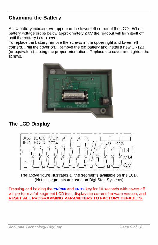
The LCD Display
The above figure illustrates all the segments available on the LCD. (Not all segments are used on Digi-Stop Systems)
Pressing and holding the ON/OFF and UNITS key for 10 seconds with power off will perform a full segment LCD test, display the current firmware version, and RESET ALL PROGRAMMING PARAMETERS TO FACTORY DEFAULTS.

Manual Part # 800-1070-001, Rev06012014 Page 10 of 16
SECTION 3 OPERATION
Readout Keys Key Timing The keys pictured above, are found on all Digi-Stop readouts, and some of them have multiple functions. Timing, which is how long a key is depressed, and the combination of the keys pressed is important. This manual uses the term ‘”momentarily” to describe a key press of shorter than 1 second. Whereas the term “press and hold” is used to describe a key press of longer than 1.5 seconds. As an example; when using a PC keyboard to type a capital letter you would “press and hold” the SHIFT key and “momentarily depress the LETTER key. In addition most of the key “functions” are executed on RELEASE, not press. This is important since some of the same keys execute different functions based on how long they are pressed and when they are released. These key operations, once tried will quickly become intuitive. On/Off Momentarily pressing the ON/OFF key will cause the readout to turn on or off. The Firmware Version of the readout is displayed on power-up when ON/OFF key is used. While the readout is on, if the stop is not moved for 15 minutes, the readout will automatically turn itself off to conserve battery life. While it is off if the stop is moved as little as .002in (.05mm), or the ON/OFF button is pressed, the readout will automatically turn itself back on with no loss of position. Units The readout can display position information in decimal inches, fractions, or millimeters. To change the current display mode, momentarily press the UNITS key. With each key press the readout will cycle through decimal inches, fractional inches and millimeters. When the readout is in 1/16 or 1/32 inch fraction mode, a series of “bars” in the upper right corner of the display, each representing 1/64th of an inch, may appear. (ie. When in 1/16 inch mode and three bars are showing, the measurement displayed is rounded down to the closest 1/16 inch and each

Accurate Technology DigiStop Page 11 of 16
illuminated bar indicates an additional 1/64 of an inch of measurement.) For better resolution, switch to 1/32 or 1/64 mode. For the best resolution and accuracy switch to a decimal mode – inches or millimeters.. When the measurement is greater than 99 63/64 inches, a +100 and/or +200 will illuminate in the upper right portion of the display to indicate this amount must be added to the displayed reading. ie: If the measurement is 154 5/8 inches, 54 5/8 and +100 will be illuminated on the display. If the measurement is -307 23/64 inches, - 7 23/64, +100 and +200 will be illuminated on the display. +, Datum, and - The + (plus), DATUM and – (minus) keys are used to change the currently displayed position to a different value. The DATUM key forces the readout to display a user programmed value. Programming Parameter Pr1 Momentarily depressing the + key increments the current position by one unit of measurement. Momentarily depressing the – key decrements the current position by one unit. Pressing and holding the + or – keys will cause the displayed position to change continuously. Holding down the key will cause the amount of change to speed up. This allows for quick adjustments over a range of large values. NOTE: While the DATUM key can be used to simply “zero” the currently displayed value, it can also be programmed to force the readout to a preset value. This can be zero, or any other displayable value. See Section 3: Readout Programming, & Programming Parameter Pr1.
Reverse Readings Reverse readings means changing the direction of readings produced by moving the stop. If the DigiStop decrements (reduces or goes negative) when it should be incrementing (increasing or going positive), the readout will need to be re-programmed for your installation (right vs left infeeds). See Section 3: Readout Programming & Programming Parameter Pr2.

Manual Part # 800-1070-001, Rev06012014 Page 12 of 16
Lock Mode To activate the Lock function Press and hold the ON/OFF key and then momentarily press the UNITS key. The word LOCK will appear in the upper left corner of the readout. When LOCK is displayed, the +, DATUM and – keys become inactive to prevent accidental changes of the (calibrated) current displayed position. To de-activate the Lock function, press and hold the ON/OFF key and then momentarily press the UNITS key. NOTE: The Lock function can also be enabled/disabled through programming. This allows a more permanent Lock function since programming can be disabled with a hardware jumper inside the readout thus preventing any front panel programming changes. See Section 3: Readout Programming, Programming Parameter Pr3.
Resolution The Digital readout can be configured to display measurements in any of three different resolutions.
1. Low– the resolution is .1in or .1mm. 2. Normal– the resolution is: .01in or .01mm. 3. High– the resolution is: .001in or .01mm
The display of fractions remains the same for all settings: 1/16, 1/32 & 1/64 See Section 3: Readout Programming & , Programming Parameter Pr4.
Incremental Measurements The readout has two measurement modes, or indexes. One is referred to as ABS or Absolute, and the other as INC, or Incremental. The absolute measurement mode allows the operator to read the current position of the stop referenced from a fixed or known position such as the saw blade. The incremental mode allows the operator to make relative distance measurements from one arbitrary point to another. The absolute position of the Digi-Stop is not lost when using the incremental mode. Absolute The readout automatically enters ABS mode when power is first applied. This is indicated by the ABS symbol in the upper left corner of the display. While in the ABS mode, all stop positions are related to the current ABS, or absolute system reference point, ie the blade.. Incremental To enter the INC mode, press and hold the UNITS key for approximately 3 seconds. The INC symbol will appear in the upper left corner of the display. When the INC mode is entered the readout will display zero (0) or the last offset

Accurate Technology DigiStop Page 13 of 16
if one was entered, and may be changed by using the + or - keys to provide a different offset. Moving the stop in either direction will display the distance moved from the initial INC starting point (plus any offset). To complete another incremental measurement from the new position, momentarily press the UNITS key. The readout will again change to 0 (or the previously programmed offset). To return to the ABS mode, press and hold the UNITS key for approximately 3 seconds. NOTES: When the readout is in incremental measuring mode the UNITS key no longer functions to change the measurement units displayed. The absolute position of the Digi-Stop is not lost when using the incremental mode. When the readout is switched back to the absolute mode the readout reflests the current stop position relative to your original calibrated absolute setting.
Circuit Board Jumpers The Digi-Stop readout has several user configurable jumpers consisting of three pins and a ‘shorting block or jumper’. The center of these three pins is ‘Common’. One end pin is labeled A and the other end pin is labeled B. JP1 FACTORY USE ONLY JP2 Programming Lockout
Position A, Front Panel Programming is ENABLED Position B, Front Panel Programming is DISABLED
JP1 JP2

Manual Part # 800-1070-001, Rev06012014 Page 14 of 16
Readout Programming Several functions of the Digi-Stop readout is user programmable. The following describes what features and functions are available and how to change the factory defaults to customize your Digi-Stop system.. To enter Programming Mode:
1. Press and hold the UNITS key then momentarily press the DATUM key. 2. The LCD will briefly display: PG on (Programming On), then
Pr 1, (indicating Programming Parameter #1) 3. Release the UNITS key 4. The value stored in Pr1 is displayed.
Once in the Programming Mode: Moving up parameter list - Momentarily press the UNITS key to advance through the Programming Parameter list, first displaying the Programming Parameter number then the currently programmed value. Moving down parameter list - Press and hold the ON/OFF key and momentarily press the UNITS key to move backward through the Programming list. Increase parameter value - Momentarily press the PLUS (+) key while displaying a Programming Parameter Value to increase the setting.
Decrease parameter value - Momentarily press the MINUS (-) key while displaying a Programming Parameter Value to decrease the setting.
Reset parameter value to default setting - Momentarily press the DATUM key while displaying a Programming Parameter Value to reset the parameter to the factory default value.
Exit programming mode - Press and hold the UNITS key. Momentarily depress the DATUM key. The LCD will briefly display: PG oFF (Programming Off), then return to normal operation. NOTE: The system will automatically exit programming mode after 60 seconds of no key activity.
Momentarily press
Press & Hold

Accurate Technology DigiStop Page 15 of 16
Programming Parameters The Digi-Stop readout programming parameters are listed below. Values in [ ] are the available range of values that can be entered for that parameter. Factory defaults are shown in Bold Red. Pr 1 – Datum Key [0 to + 999.999in] or [0 to +9999.99mm] The programmed value that will be recalled whenever the DATUM key is pressed during normal operation. Default = 0.00 Pr 2 – Reverse Readings [0 or 1] This parameter controls the direction of travel (positive vs. negative) when the stop is moved. Default = 0 Pr 3 – Key Lockout [0 or 1] This parameter controls the operation of the +, - and DATUM keys. If enabled, (set to 1), these keys will not function and the LOCK symbol will appear on the display. This prevents accidental changes when pressing these keys during normal operation. Default = 0 Pr 4 – Readout Resolution [1, 2, 3 ] This parameter sets the number of places to the right of the decimal point on the readout. Default = 2 A value of 1 – Low - will display x.x. A value of 2 – Normal -will display x.xx A value of 3 – High - will display x.xxx
Frequently Asked Questions What F/W (Firmware) version do I have?
The readout will display the firmware version on power up. What does no Enc mean?
If the encoder cable is unplugged from the readout , no Enc will appear on the display. To clear: Be sure the encoder is on the scale and plugged into the readout.
The readings are “backwards”? You can change reading direction of the Digi-Stop by changing the value of Programming Parameter Pr 2.
What does b FAIL mean? When the readout displays this message it means the battery voltage has dropped to a level where reliable operation is no longer possible. Install new batteries to clear this message.
What does P FAIL mean? When the readout displays this message it means the battery voltage has dropped to a level where reliable programming is not possible. Install new batteries to clear this message.

Manual Part # 800-1070-001, Rev06012014 Page 16 of 16
Thank you for choosing an AMERICAN MADE PRODUCT
Accurate Technology, Inc. 270 Rutledge Rd. Unit E Fletcher, NC 28732 USA
828.654.7920
Please register your product at: http://www.proscale.com/registration.htm
This manual is available online at:
www.proscale.com
Manual P/N 800-1070-001 Rev06012014.
Copyright Accurate Technology 2014