Embed Size (px)
Citation preview
Digital Band-pass Modulation
PROF. MICHAEL TSAI
2011/11/10
Band-pass Signal Representation
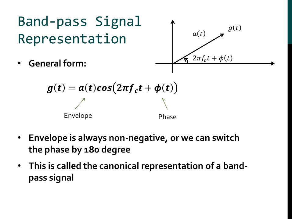
• General form:
𝒈 𝒕 = 𝒂 𝒕 𝒄𝒐𝒔 𝟐𝝅𝒇𝒄𝒕 + 𝝓 𝒕
• Envelope is always non-negative, or we can switch the phase by 180 degree
• This is called the canonical representation of a band-pass signal
Envelope Phase
𝑎 𝑡
2𝜋𝑓𝑐𝑡 + 𝜙 𝑡
𝑔 𝑡
Band-pass Signal Representation
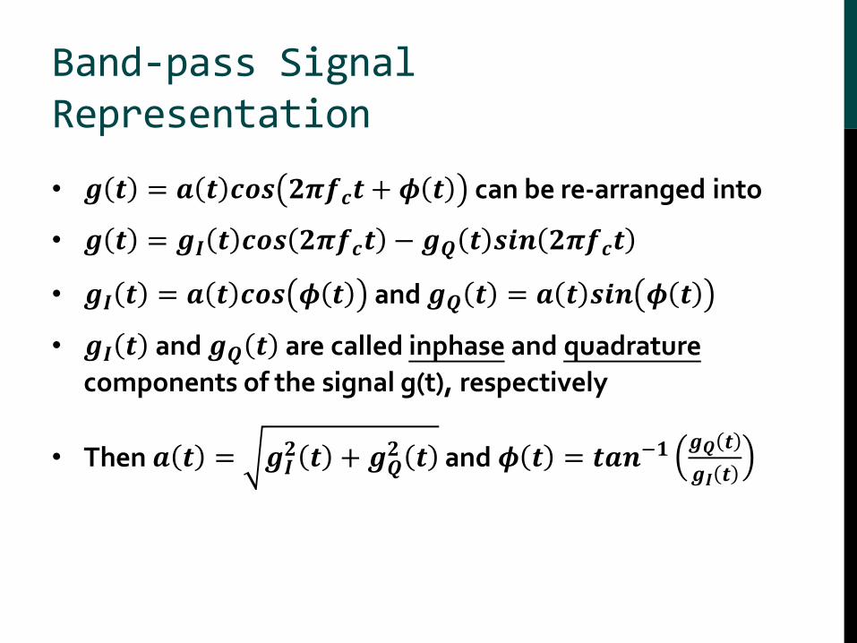
• 𝒈 𝒕 = 𝒂 𝒕 𝒄𝒐𝒔 𝟐𝝅𝒇𝒄𝒕 + 𝝓 𝒕 can be re-arranged into
• 𝒈 𝒕 = 𝒈𝑰 𝒕 𝒄𝒐𝒔 𝟐𝝅𝒇𝒄𝒕 − 𝒈𝑸 𝒕 𝒔𝒊𝒏 𝟐𝝅𝒇𝒄𝒕
• 𝒈𝑰 𝒕 = 𝒂 𝒕 𝒄𝒐𝒔 𝝓 𝒕 and 𝒈𝑸 𝒕 = 𝒂 𝒕 𝒔𝒊𝒏 𝝓 𝒕
• 𝒈𝑰 𝒕 and 𝒈𝑸 𝒕 are called inphase and quadrature
components of the signal g(t), respectively
• Then 𝒂 𝒕 = 𝒈𝑰𝟐 𝒕 + 𝒈𝑸
𝟐 𝒕 and 𝝓 𝒕 = 𝒕𝒂𝒏−𝟏𝒈𝑸 𝒕
𝒈𝑰 𝒕
Band-pass Signal Representation
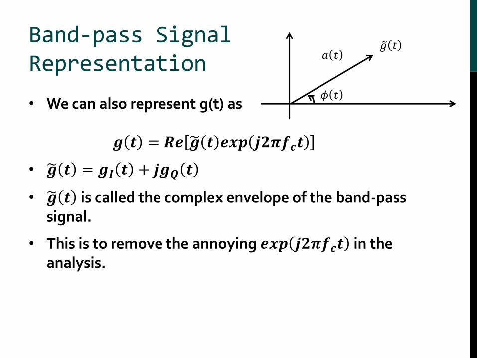
• We can also represent g(t) as
𝒈 𝒕 = 𝑹𝒆 𝒈 𝒕 𝒆𝒙𝒑 𝒋𝟐𝝅𝒇𝒄𝒕
• 𝒈 𝒕 = 𝒈𝑰 𝒕 + 𝒋𝒈𝑸 𝒕
• 𝒈 𝒕 is called the complex envelope of the band-pass signal.
• This is to remove the annoying 𝒆𝒙𝒑 𝒋𝟐𝝅𝒇𝒄𝒕 in the analysis.
𝑎 𝑡
𝜙 𝑡
𝑔 𝑡
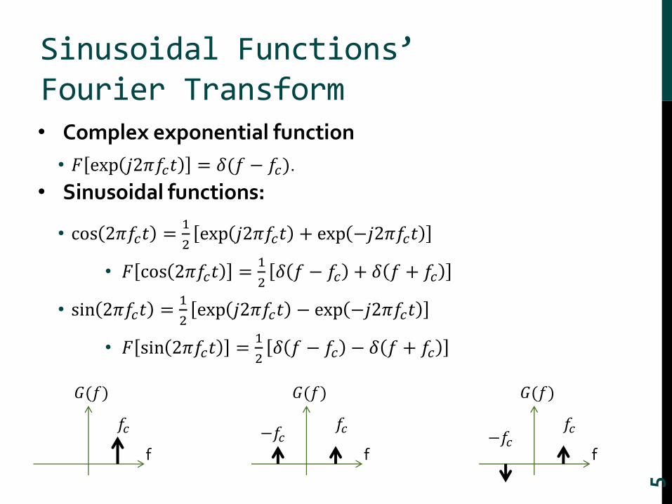
Sinusoidal Functions’ Fourier Transform • Complex exponential function
• 𝐹 exp 𝑗2𝜋𝑓𝑐𝑡 = 𝛿(𝑓 − 𝑓𝑐).
• Sinusoidal functions:
• cos 2𝜋𝑓𝑐𝑡 =1
2exp 𝑗2𝜋𝑓𝑐𝑡 + exp −𝑗2𝜋𝑓𝑐𝑡
• 𝐹 cos 2𝜋𝑓𝑐𝑡 =1
2𝛿 𝑓 − 𝑓𝑐 + 𝛿 𝑓 + 𝑓𝑐
• sin 2𝜋𝑓𝑐𝑡 =1
2exp 𝑗2𝜋𝑓𝑐𝑡 − exp −𝑗2𝜋𝑓𝑐𝑡
• 𝐹 sin 2𝜋𝑓𝑐𝑡 =1
2𝛿 𝑓 − 𝑓𝑐 − 𝛿 𝑓 + 𝑓𝑐
5
f
𝐺(𝑓)
𝑓𝑐
f
𝐺(𝑓)
𝑓𝑐 −𝑓𝑐 −𝑓𝑐
f
𝐺(𝑓)
𝑓𝑐
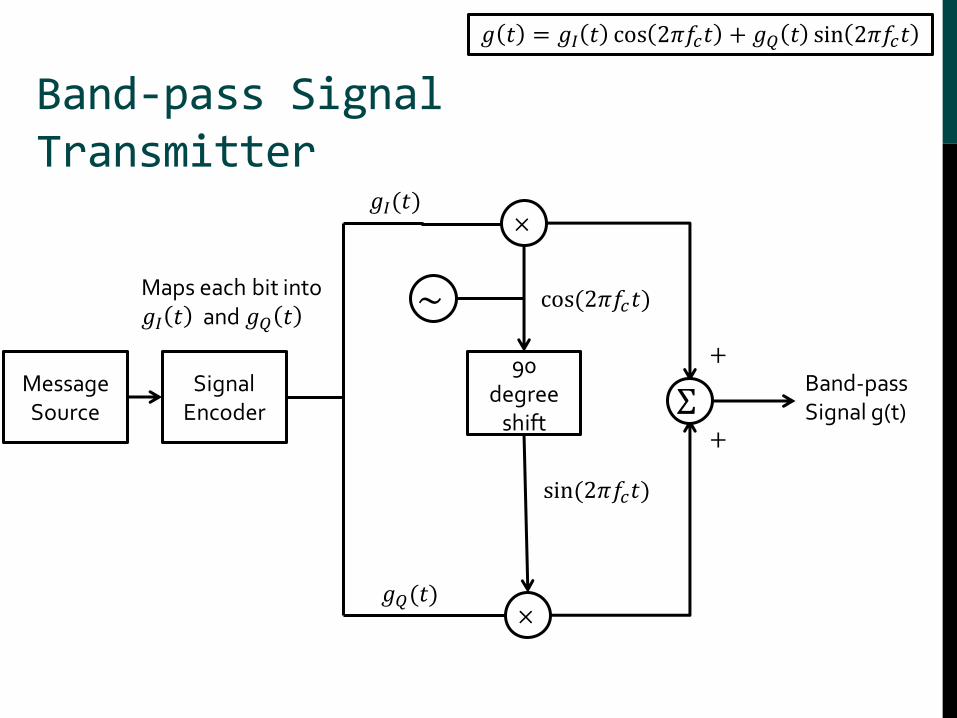
Band-pass Signal Transmitter
Signal Encoder
90 degree
shift
×
×
∼
Message Source Σ
Band-pass Signal g(t)
cos(2𝜋𝑓𝑐𝑡)
sin(2𝜋𝑓𝑐𝑡)
𝑔𝐼(𝑡)
𝑔𝑄(𝑡)
𝑔 𝑡 = 𝑔𝐼 𝑡 cos 2𝜋𝑓𝑐𝑡 + 𝑔𝑄 𝑡 sin 2𝜋𝑓𝑐𝑡
+
+
Maps each bit into 𝑔𝐼 𝑡 and 𝑔𝑄 𝑡
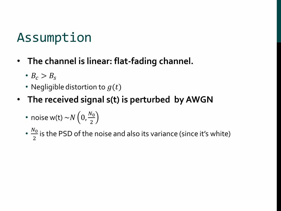
Assumption
• The channel is linear: flat-fading channel.
• 𝐵𝑐 > 𝐵𝑠
• Negligible distortion to 𝑔(𝑡)
• The received signal s(t) is perturbed by AWGN
• noise w(t) ~𝑁 0,𝑁0
2
•𝑁0
2 is the PSD of the noise and also its variance (since it’s white)
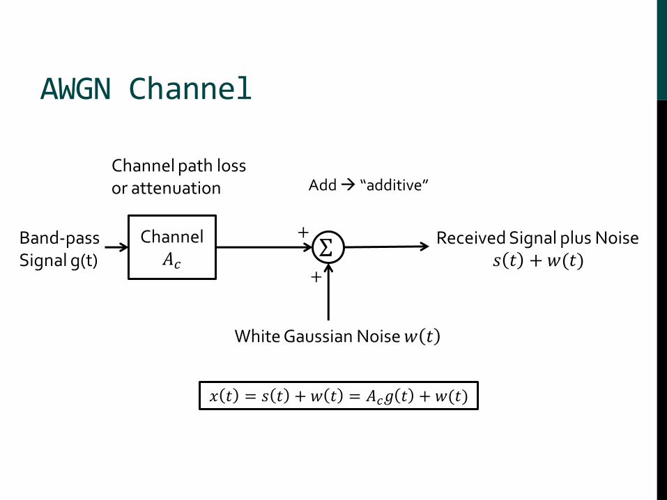
AWGN Channel
Channel 𝐴𝑐
Band-pass Signal g(t)
Σ +
+
White Gaussian Noise 𝑤 𝑡
Received Signal plus Noise 𝑠 𝑡 + 𝑤(𝑡)
Channel path loss or attenuation Add “additive”
𝑥 𝑡 = 𝑠 𝑡 + 𝑤 𝑡 = 𝐴𝑐𝑔 𝑡 + 𝑤(𝑡)
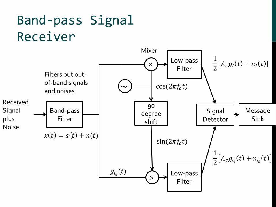
Band-pass Signal Receiver
Band-pass Filter
90 degree
shift
×
×
∼
Message Sink
Received Signal plus Noise
cos(2𝜋𝑓𝑐𝑡)
sin(2𝜋𝑓𝑐𝑡)
𝑔𝑄(𝑡)
Filters out out-of-band signals and noises
𝑥 𝑡 = 𝑠 𝑡 + 𝑛(𝑡)
Low-pass Filter
Signal Detector
Low-pass Filter
1
2𝐴𝑐𝑔𝐼 𝑡 + 𝑛𝐼 𝑡
1
2𝐴𝑐𝑔𝑄 𝑡 + 𝑛𝑄 𝑡
Mixer
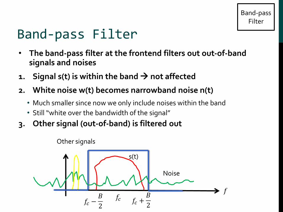
Band-pass Filter • The band-pass filter at the frontend filters out out-of-band
signals and noises
1. Signal s(t) is within the band not affected
2. White noise w(t) becomes narrowband noise n(t)
• Much smaller since now we only include noises within the band
• Still “white over the bandwidth of the signal”
3. Other signal (out-of-band) is filtered out
Band-pass Filter
𝑓 𝑓𝑐
𝑓𝑐 −𝐵
2 𝑓𝑐 +
𝐵
2
Other signals
Noise
s(t)
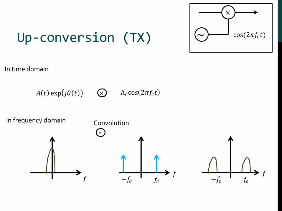
Up-conversion (TX)
×
∼ cos(2𝜋𝑓𝑐𝑡)
𝑓 𝑓
𝐴 𝑡 exp 𝑗𝜃 𝑡 Accos 2𝜋𝑓𝑐𝑡 ×
In time domain
In frequency domain
∗
Convolution
−𝑓𝑐 𝑓𝑐 𝑓
−𝑓𝑐 𝑓𝑐
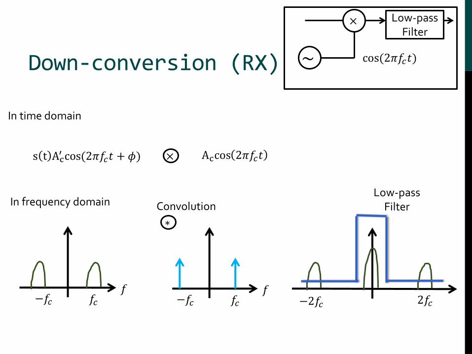
Down-conversion (RX)
×
∼ cos(2𝜋𝑓𝑐𝑡)
s t Ac′ cos(2𝜋𝑓𝑐𝑡 + 𝜙) Accos 2𝜋𝑓𝑐𝑡 ×
In time domain
In frequency domain
∗
Convolution
Low-pass Filter
𝑓 −𝑓𝑐 𝑓𝑐
𝑓 −𝑓𝑐 𝑓𝑐
𝑓 −2𝑓𝑐 2𝑓𝑐
Low-pass Filter
Signal Detector
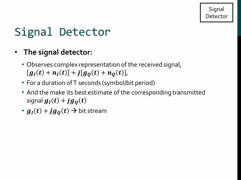
• The signal detector:
• Observes complex representation of the received signal, 𝒈𝑰 𝒕 + 𝒏𝑰 𝒕 + 𝒋[𝒈𝑸 𝒕 + 𝒏𝑸 𝒕 ],
• For a duration of T seconds (symbol/bit period)
• And the make its best estimate of the corresponding transmitted signal 𝒈𝑰 𝒕 + 𝒋𝒈𝑸 𝒕
• 𝒈𝑰 𝒕 + 𝒋𝒈𝑸 𝒕 bit stream
Signal Detector
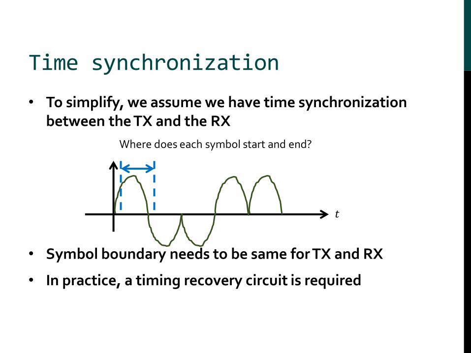
Time synchronization
• To simplify, we assume we have time synchronization between the TX and the RX
• Symbol boundary needs to be same for TX and RX
• In practice, a timing recovery circuit is required
𝑡
Where does each symbol start and end?
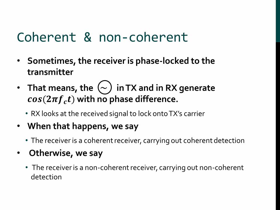
Coherent & non-coherent
• Sometimes, the receiver is phase-locked to the transmitter
• That means, the in TX and in RX generate 𝒄𝒐𝒔(𝟐𝝅𝒇𝒄𝒕) with no phase difference.
• RX looks at the received signal to lock onto TX’s carrier
• When that happens, we say
• The receiver is a coherent receiver, carrying out coherent detection
• Otherwise, we say
• The receiver is a non-coherent receiver, carrying out non-coherent detection
∼
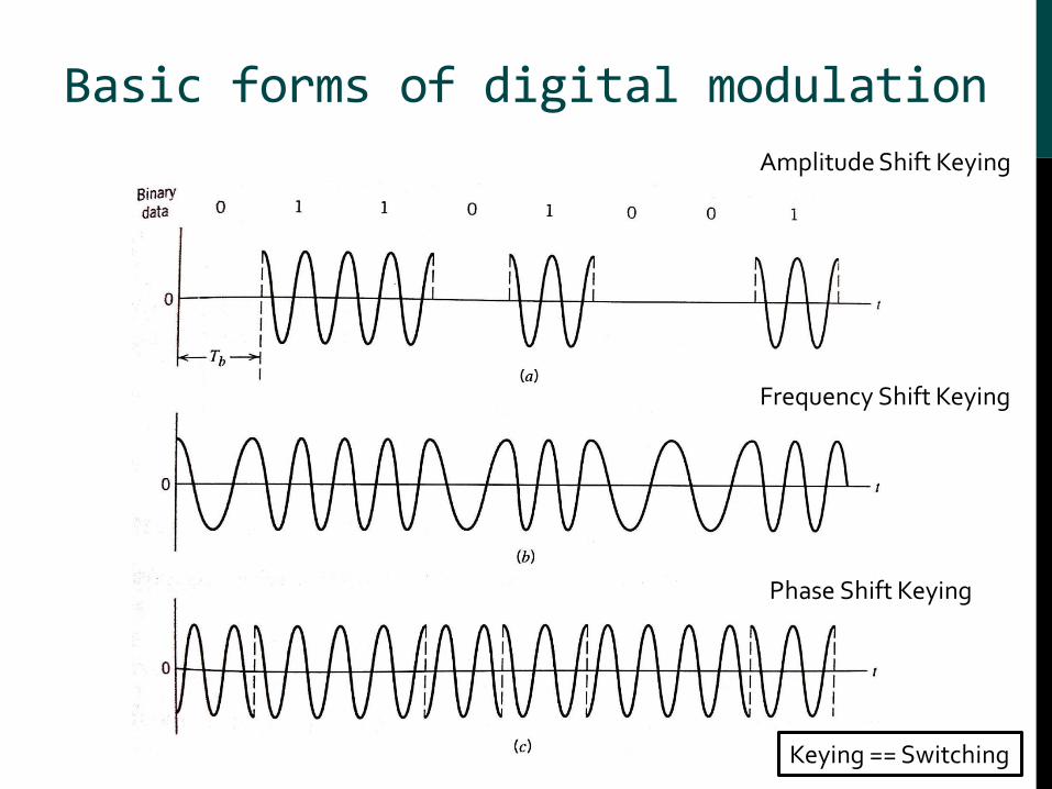
Basic forms of digital modulation
Amplitude Shift Keying
Frequency Shift Keying
Phase Shift Keying
Keying == Switching
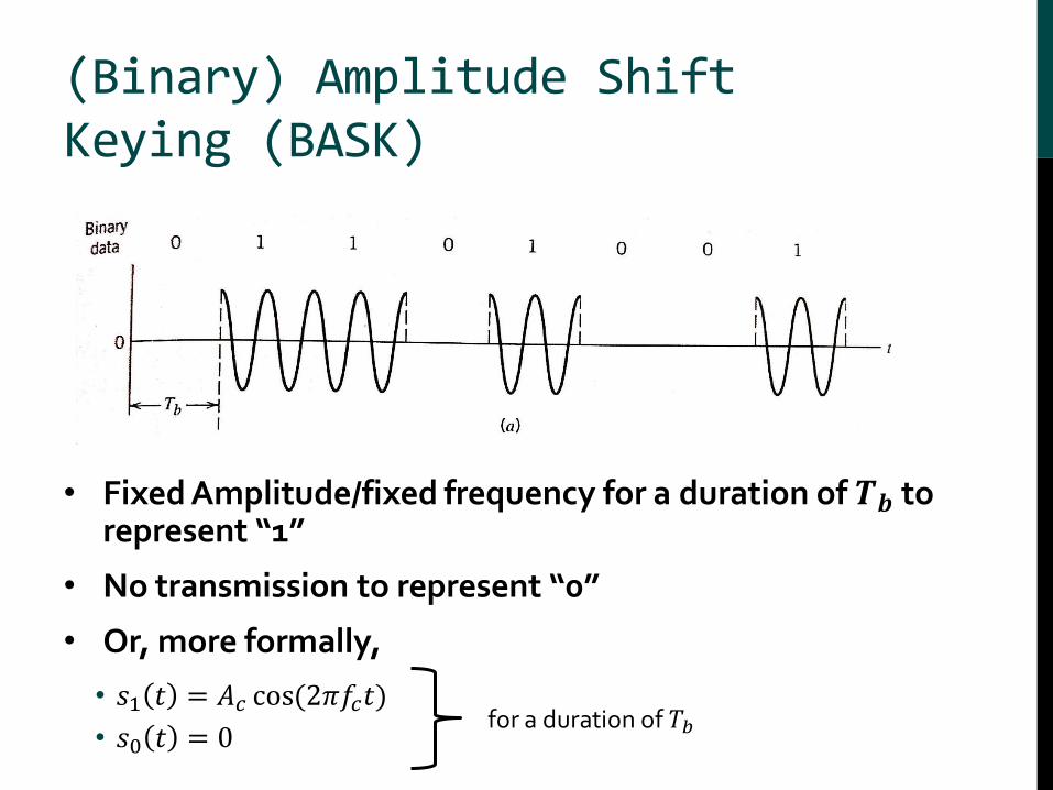
(Binary) Amplitude Shift Keying (BASK)
• Fixed Amplitude/fixed frequency for a duration of 𝑻𝒃 to represent “1”
• No transmission to represent “0”
• Or, more formally,
• 𝑠1 𝑡 = 𝐴𝑐 cos(2𝜋𝑓𝑐𝑡)
• 𝑠0 𝑡 = 0
for a duration of 𝑇𝑏
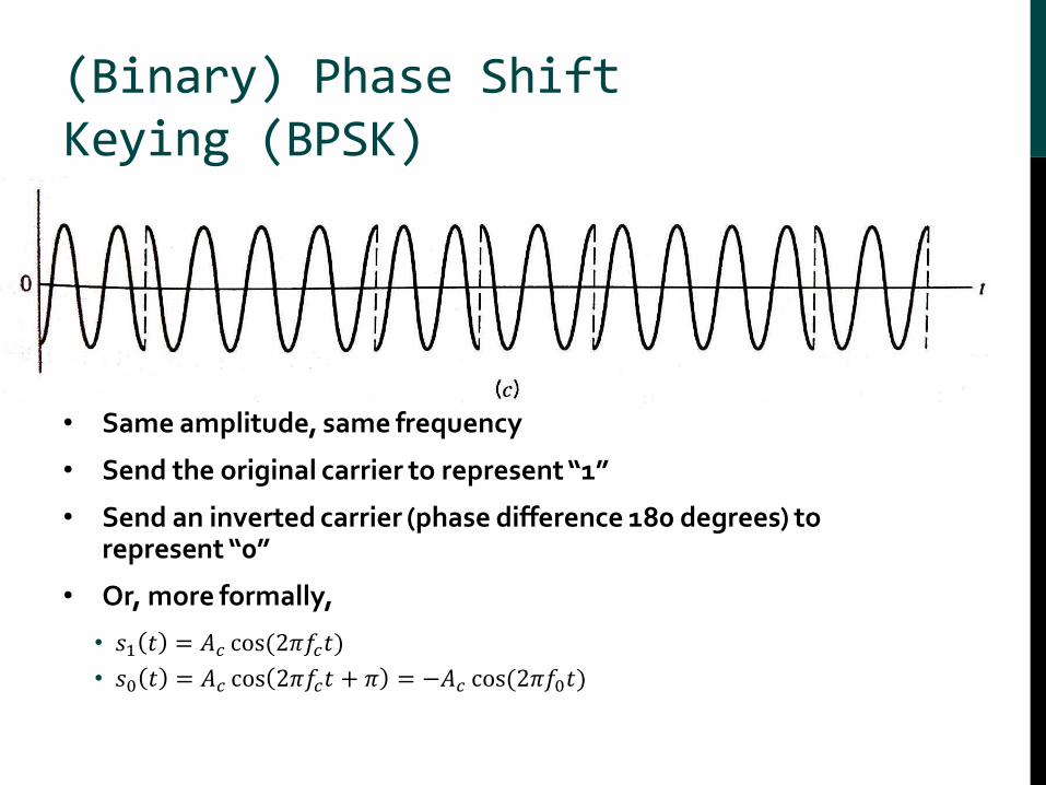
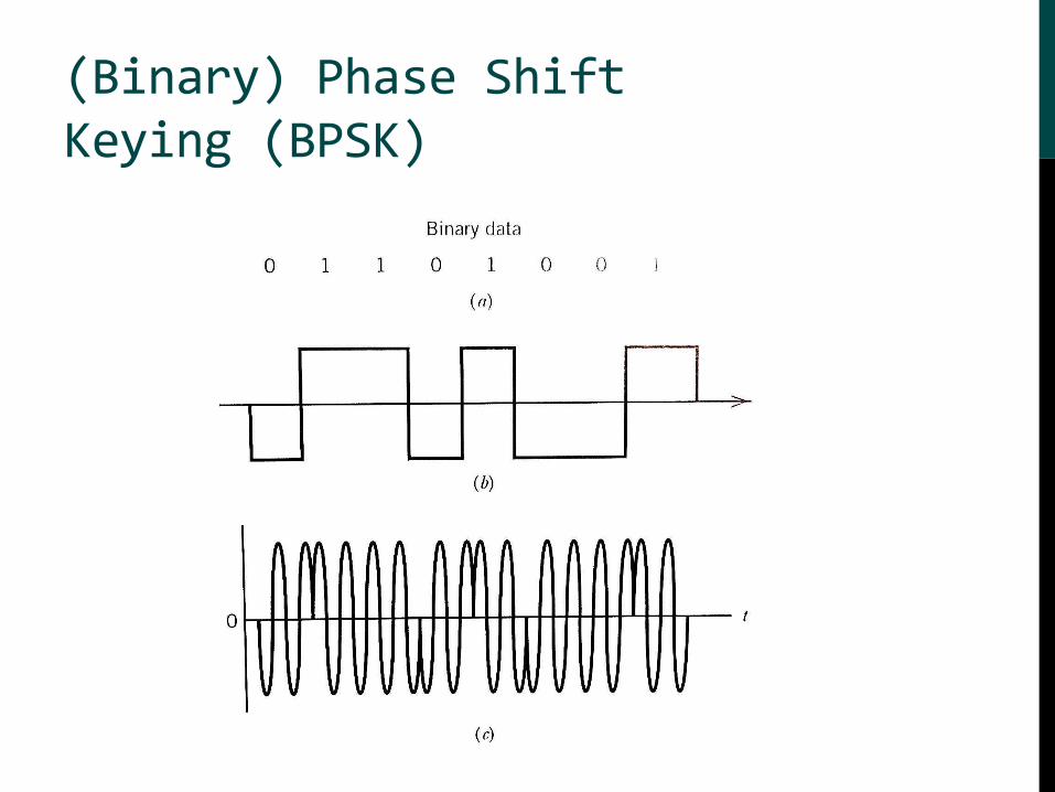
(Binary) Phase Shift Keying (BPSK)
• Same amplitude, same frequency
• Send the original carrier to represent “1”
• Send an inverted carrier (phase difference 180 degrees) to represent “0”
• Or, more formally,
• 𝑠1 𝑡 = 𝐴𝑐 cos(2𝜋𝑓𝑐𝑡)
• 𝑠0 𝑡 = 𝐴𝑐 cos 2𝜋𝑓𝑐𝑡 + 𝜋 = −𝐴𝑐 cos(2𝜋𝑓0𝑡)
(Binary) Phase Shift Keying (BPSK)
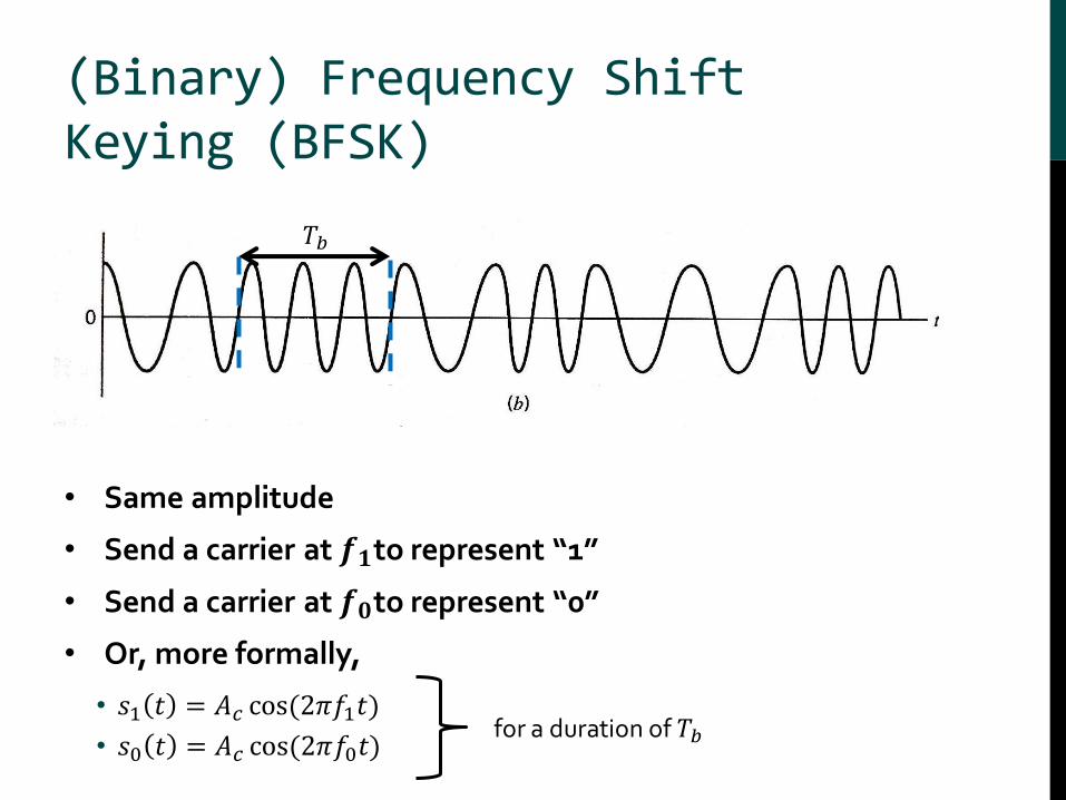
(Binary) Frequency Shift Keying (BFSK)
𝑇𝑏
• Same amplitude
• Send a carrier at 𝒇𝟏to represent “1”
• Send a carrier at 𝒇𝟎to represent “0”
• Or, more formally,
• 𝑠1 𝑡 = 𝐴𝑐 cos(2𝜋𝑓1𝑡)
• 𝑠0 𝑡 = 𝐴𝑐 cos(2𝜋𝑓0𝑡)
for a duration of 𝑇𝑏
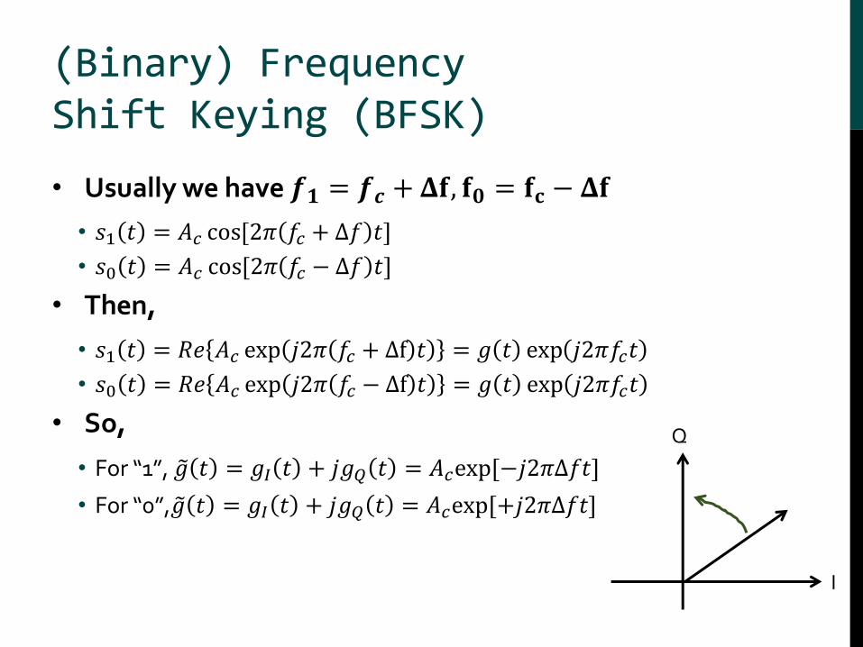
(Binary) Frequency Shift Keying (BFSK)
• Usually we have 𝒇𝟏 = 𝒇𝒄 +𝚫𝐟, 𝐟𝟎 = 𝐟𝐜 − 𝚫𝐟
• 𝑠1 𝑡 = 𝐴𝑐 cos[2𝜋 𝑓𝑐 + Δ𝑓 𝑡]
• 𝑠0 𝑡 = 𝐴𝑐 cos[2𝜋 𝑓𝑐 − Δ𝑓 𝑡]
• Then,
• 𝑠1 𝑡 = 𝑅𝑒 𝐴𝑐 exp 𝑗2𝜋 𝑓𝑐 + Δf 𝑡 = 𝑔 𝑡 exp 𝑗2𝜋𝑓𝑐𝑡
• 𝑠0 𝑡 = 𝑅𝑒 𝐴𝑐 exp 𝑗2𝜋 𝑓𝑐 − Δf 𝑡 = 𝑔 𝑡 exp 𝑗2𝜋𝑓𝑐𝑡
• So,
• For “1”, 𝑔 𝑡 = 𝑔𝐼 𝑡 + 𝑗𝑔𝑄 𝑡 = 𝐴𝑐exp[−𝑗2𝜋Δ𝑓𝑡]
• For “0”,𝑔 𝑡 = 𝑔𝐼 𝑡 + 𝑗𝑔𝑄 𝑡 = 𝐴𝑐exp[+𝑗2𝜋Δ𝑓𝑡]
I
Q
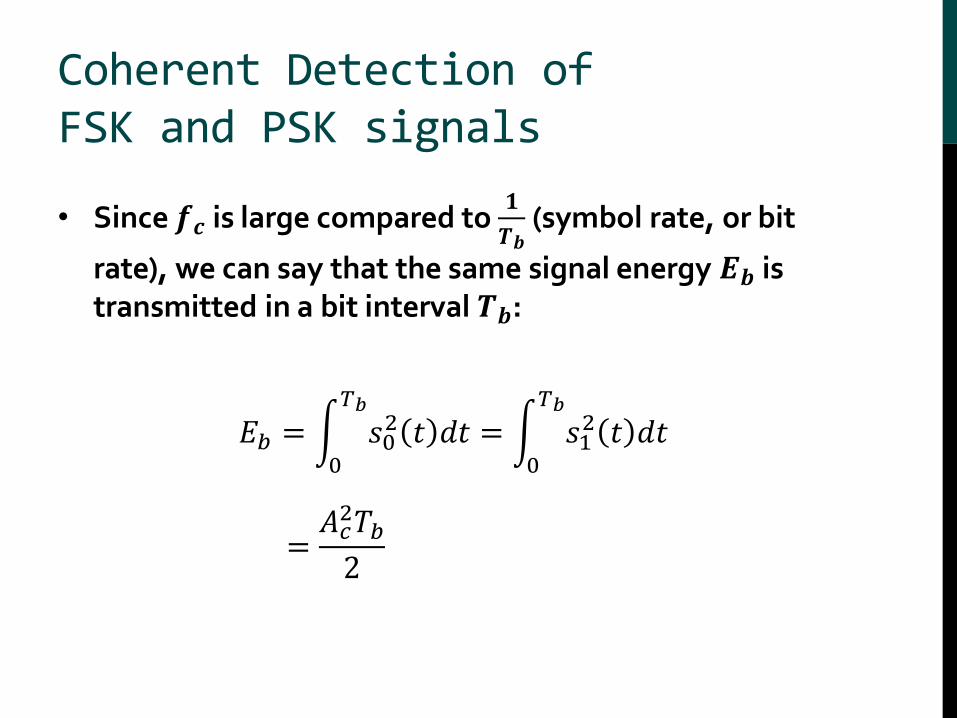
Coherent Detection of FSK and PSK signals
• Since 𝒇𝒄 is large compared to 𝟏
𝑻𝒃 (symbol rate, or bit
rate), we can say that the same signal energy 𝑬𝒃 is transmitted in a bit interval 𝑻𝒃:
𝐸𝑏 = 𝑠02 𝑡 𝑑𝑡
𝑇𝑏
0
= 𝑠12 𝑡 𝑑𝑡
𝑇𝑏
0
=𝐴𝑐2𝑇𝑏2
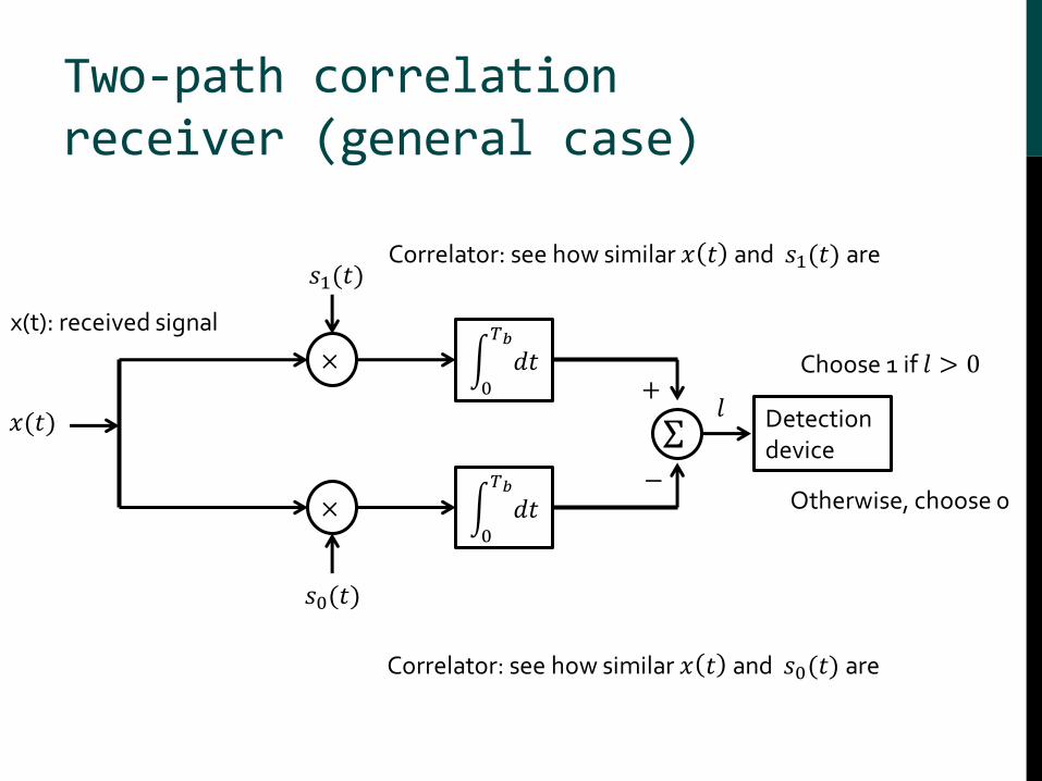
Two-path correlation receiver (general case)
𝑑𝑡𝑇𝑏
0
𝑑𝑡𝑇𝑏
0
×
×
Σ +
−
Detection device
Choose 1 if 𝑙 > 0
Otherwise, choose 0
𝑥(𝑡)
x(t): received signal
𝑠1(𝑡)
𝑠0(𝑡)
Correlator: see how similar 𝑥 𝑡 and 𝑠1(𝑡) are
Correlator: see how similar 𝑥 𝑡 and 𝑠0(𝑡) are
𝑙
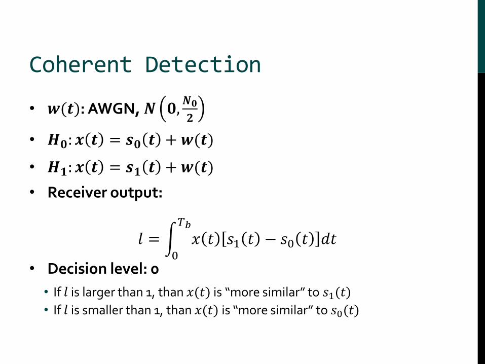
Coherent Detection
• 𝒘(𝒕): AWGN, 𝑵 𝟎,𝑵𝟎
𝟐
• 𝑯𝟎: 𝒙 𝒕 = 𝒔𝟎 𝒕 + 𝒘(𝒕)
• 𝑯𝟏: 𝒙 𝒕 = 𝒔𝟏 𝒕 + 𝒘(𝒕)
• Receiver output:
• Decision level: 0
• If 𝑙 is larger than 1, than 𝑥(𝑡) is “more similar” to 𝑠1(𝑡)
• If 𝑙 is smaller than 1, than 𝑥(𝑡) is “more similar” to 𝑠0(𝑡)
𝑙 = 𝑥 𝑡 𝑠1 𝑡 − 𝑠0 𝑡 𝑑𝑡𝑇𝑏
0
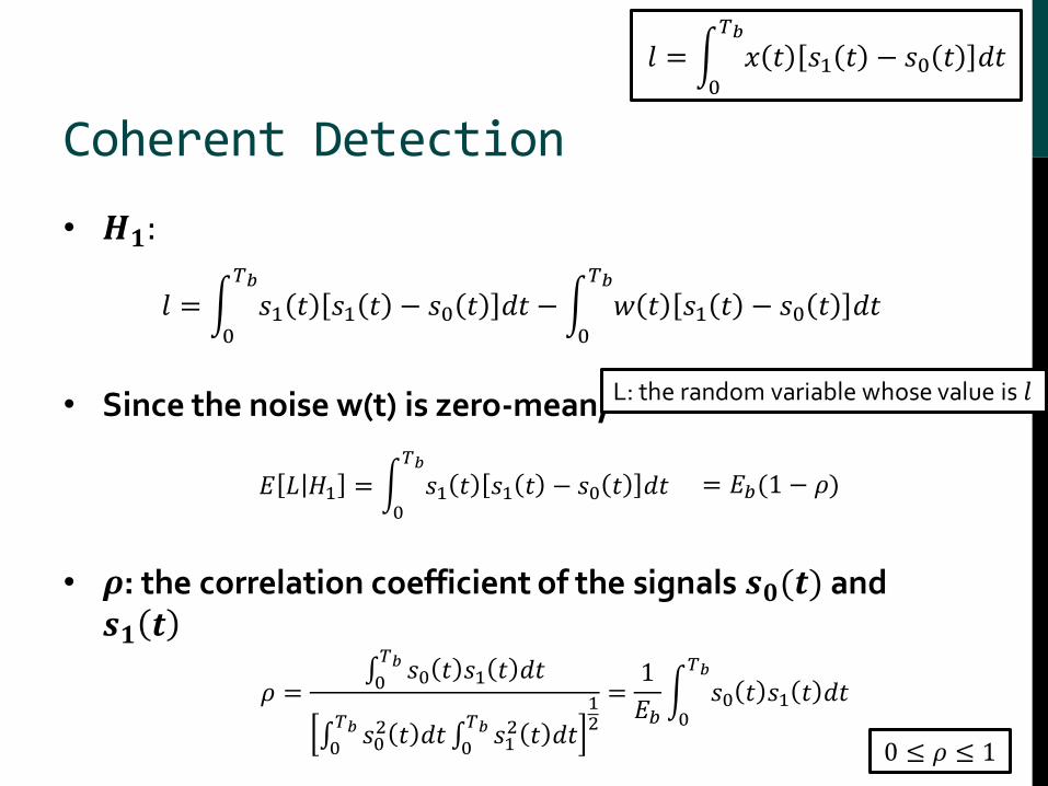
Coherent Detection
• 𝑯𝟏:
• Since the noise w(t) is zero-mean,
• 𝝆: the correlation coefficient of the signals 𝒔𝟎(𝒕) and 𝒔𝟏 𝒕
𝑙 = 𝑠1 𝑡 𝑠1 𝑡 − 𝑠0 𝑡 𝑑𝑡𝑇𝑏
0
− 𝑤 𝑡 𝑠1 𝑡 − 𝑠0 𝑡 𝑑𝑡𝑇𝑏
0
𝑙 = 𝑥 𝑡 𝑠1 𝑡 − 𝑠0 𝑡 𝑑𝑡𝑇𝑏
0
𝐸 𝐿 𝐻1 = 𝑠1 𝑡 𝑠1 𝑡 − 𝑠0 𝑡 𝑑𝑡𝑇𝑏
0
= 𝐸𝑏(1 − 𝜌)
𝜌 = 𝑠0 𝑡 𝑠1 𝑡 𝑑𝑡𝑇𝑏0
𝑠02 𝑡 𝑑𝑡
𝑇𝑏0
𝑠12 𝑡 𝑑𝑡
𝑇𝑏0
12
=1
𝐸𝑏 𝑠0 𝑡 𝑠1 𝑡 𝑑𝑡𝑇𝑏
0
L: the random variable whose value is 𝑙
0 ≤ 𝜌 ≤ 1
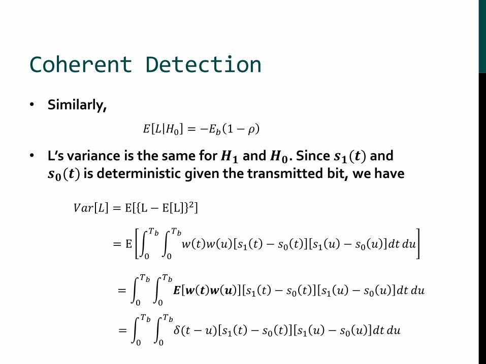
Coherent Detection
• Similarly,
• L’s variance is the same for 𝑯𝟏 and 𝑯𝟎. Since 𝒔𝟏(𝒕) and 𝒔𝟎(𝒕) is deterministic given the transmitted bit, we have
𝐸 𝐿 𝐻0 = −𝐸𝑏 1 − 𝜌
𝑉𝑎𝑟 𝐿 = E L − E L 2
= E 𝑤 𝑡 𝑤 𝑢 𝑠1 𝑡 − 𝑠0 𝑡 𝑠1 𝑢 − 𝑠0 𝑢 𝑑𝑡𝑇𝑏
0
𝑑𝑢𝑇𝑏
0
= 𝑬 𝒘 𝒕 𝒘 𝒖 𝑠1 𝑡 − 𝑠0 𝑡 𝑠1 𝑢 − 𝑠0 𝑢 𝑑𝑡𝑇𝑏
0
𝑑𝑢𝑇𝑏
0
= 𝛿(𝑡 − 𝑢) 𝑠1 𝑡 − 𝑠0 𝑡 𝑠1 𝑢 − 𝑠0 𝑢 𝑑𝑡𝑇𝑏
0
𝑑𝑢𝑇𝑏
0
= 𝛿(𝑡 − 𝑢) 𝑠1 𝑡 − 𝑠0 𝑡 𝑠1 𝑢 − 𝑠0 𝑢 𝑑𝑡𝑇𝑏
0
𝑑𝑢𝑇𝑏
0
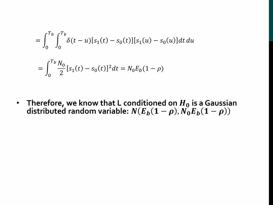
= 𝑁02
𝑠1 𝑡 − 𝑠0 𝑡 2𝑑𝑡𝑇𝑏
0
= 𝑁0𝐸𝑏(1 − 𝜌)
• Therefore, we know that L conditioned on 𝑯𝟎 is a Gaussian distributed random variable: 𝑵 𝑬𝒃 𝟏 − 𝝆 ,𝑵𝟎𝑬𝒃 𝟏 − 𝝆
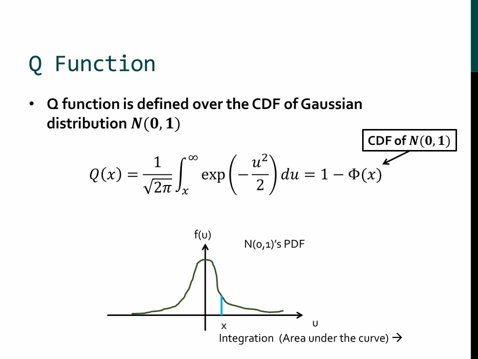
Q Function
• Q function is defined over the CDF of Gaussian distribution 𝑵(𝟎, 𝟏)
𝑄 𝑥 =1
2𝜋 exp −
𝑢2
2𝑑𝑢
∞
𝑥
= 1 −Φ(𝑥)
CDF of 𝑵(𝟎, 𝟏)
N(0,1)’s PDF
u
f(u)
Integration (Area under the curve) x
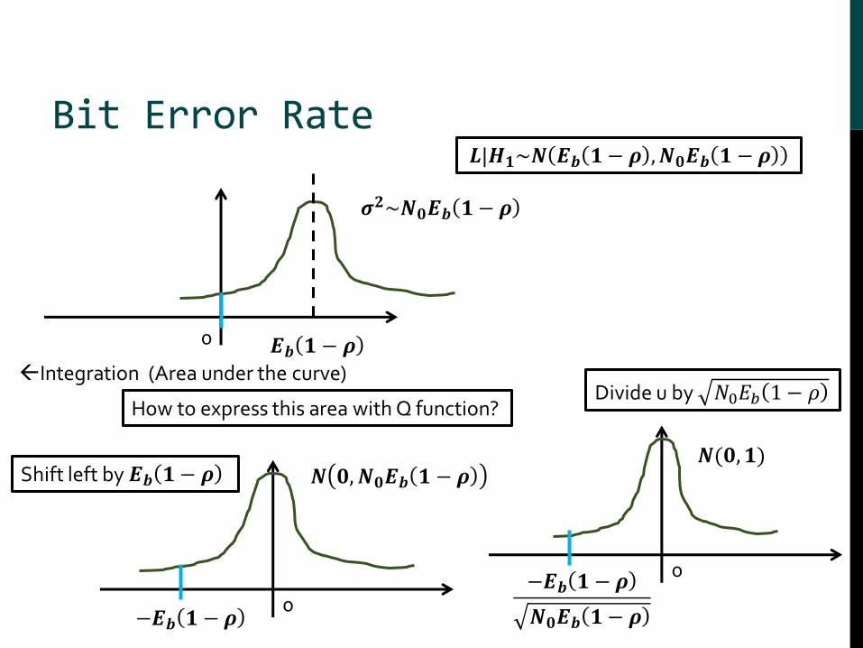
Bit Error Rate 𝑳|𝑯𝟏~𝑵 𝑬𝒃 𝟏 − 𝝆 ,𝑵𝟎𝑬𝒃 𝟏 − 𝝆
𝑬𝒃 𝟏 − 𝝆
𝝇𝟐~𝑵𝟎𝑬𝒃 𝟏 − 𝝆
Integration (Area under the curve)
0
How to express this area with Q function?
−𝑬𝒃 𝟏 − 𝝆 0
Shift left by 𝑬𝒃 𝟏 − 𝝆
−𝑬𝒃 𝟏 − 𝝆
𝑵𝟎𝑬𝒃 𝟏 − 𝝆
0
Divide u by 𝑁0𝐸𝑏 1 − 𝜌
𝑵 𝟎,𝑵𝟎𝑬𝒃 𝟏 − 𝝆 𝑵(𝟎, 𝟏)
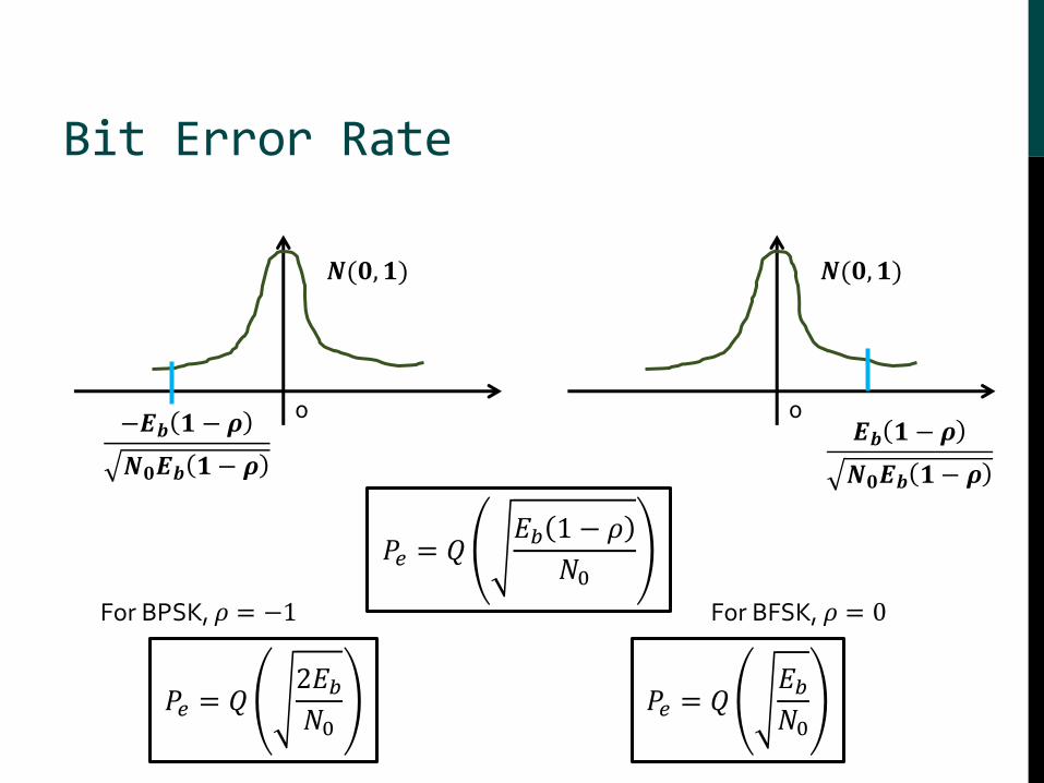
Bit Error Rate
−𝑬𝒃 𝟏 − 𝝆
𝑵𝟎𝑬𝒃 𝟏 − 𝝆
0
𝑵(𝟎, 𝟏)
𝑬𝒃 𝟏 − 𝝆
𝑵𝟎𝑬𝒃 𝟏− 𝝆
0
𝑵(𝟎, 𝟏)
𝑃𝑒 = 𝑄𝐸𝑏 1 − 𝜌
𝑁0
𝑃𝑒 = 𝑄2𝐸𝑏𝑁0
𝑃𝑒 = 𝑄𝐸𝑏𝑁0
For BPSK, 𝜌 = −1 For BFSK, 𝜌 = 0
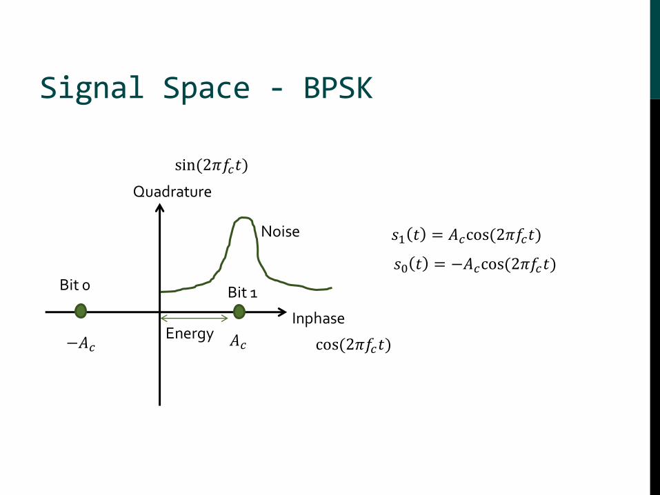
Signal Space - BPSK
Inphase
Quadrature
sin(2𝜋𝑓𝑐𝑡)
cos(2𝜋𝑓𝑐𝑡) −𝐴𝑐 𝐴𝑐
Bit 0 Bit 1
𝑠1 𝑡 = 𝐴𝑐cos(2𝜋𝑓𝑐𝑡)
𝑠0 𝑡 = −𝐴𝑐cos(2𝜋𝑓𝑐𝑡)
Noise
Energy
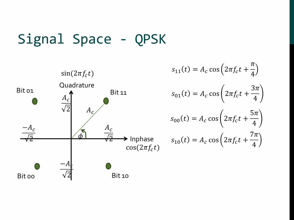
Signal Space - QPSK
Inphase
Quadrature
sin(2𝜋𝑓𝑐𝑡)
cos(2𝜋𝑓𝑐𝑡)
Bit 01 Bit 11
𝑠11 𝑡 = 𝐴𝑐 cos 2𝜋𝑓𝑐𝑡 +𝜋
4
𝑠00 𝑡 = 𝐴𝑐 cos 2𝜋𝑓𝑐𝑡 +5𝜋
4
Bit 10 Bit 00
𝐴𝑐
2
−𝐴𝑐
2
−𝐴𝑐
2
𝐴𝑐
2
𝐴𝑐
𝑠01 𝑡 = 𝐴𝑐 cos 2𝜋𝑓𝑐𝑡 +3𝜋
4
𝑠10 𝑡 = 𝐴𝑐 cos 2𝜋𝑓𝑐𝑡 +7𝜋
4
𝜙
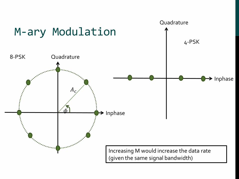
M-ary Modulation
Inphase
Quadrature
𝐴𝑐
𝜙
8-PSK
Inphase
Quadrature
4-PSK
Increasing M would increase the data rate (given the same signal bandwidth)
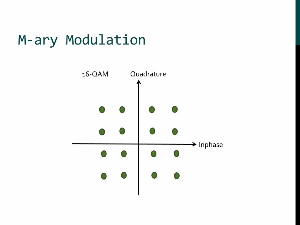
M-ary Modulation
Inphase
Quadrature 16-QAM
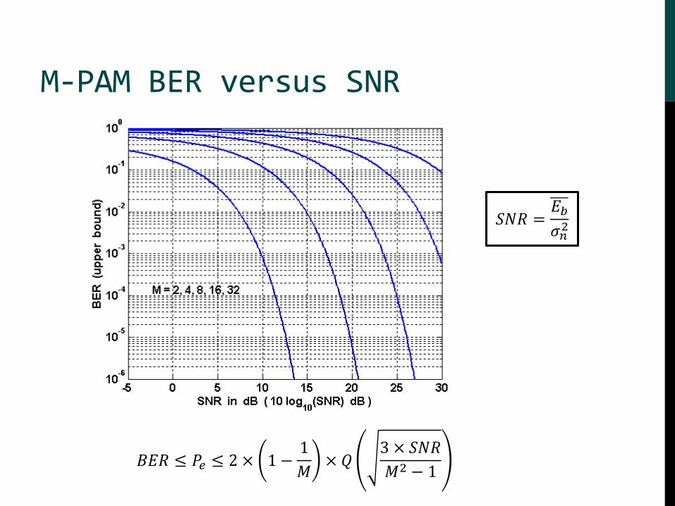
M-PAM BER versus SNR
𝐵𝐸𝑅 ≤ 𝑃𝑒 ≤ 2 × 1 −1
𝑀× 𝑄
3 × 𝑆𝑁𝑅
𝑀2 − 1
𝑆𝑁𝑅 =𝐸𝑏
𝜍𝑛2
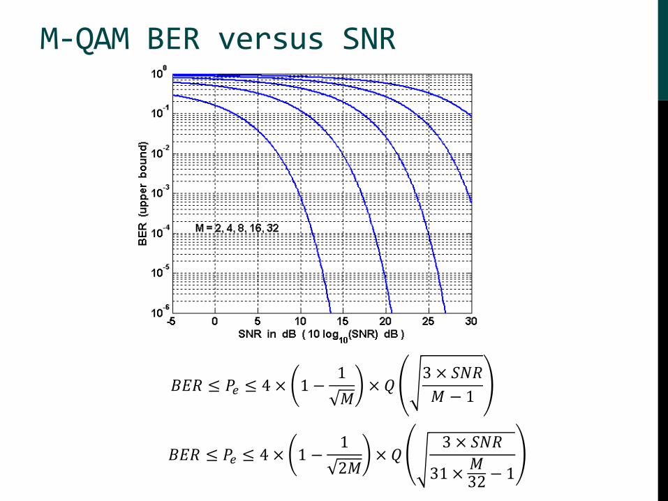
M-QAM BER versus SNR
𝐵𝐸𝑅 ≤ 𝑃𝑒 ≤ 4 × 1 −1
𝑀× 𝑄
3 × 𝑆𝑁𝑅
𝑀 − 1
𝐵𝐸𝑅 ≤ 𝑃𝑒 ≤ 4 × 1 −1
2𝑀× 𝑄
3 × 𝑆𝑁𝑅
31 ×𝑀32 − 1
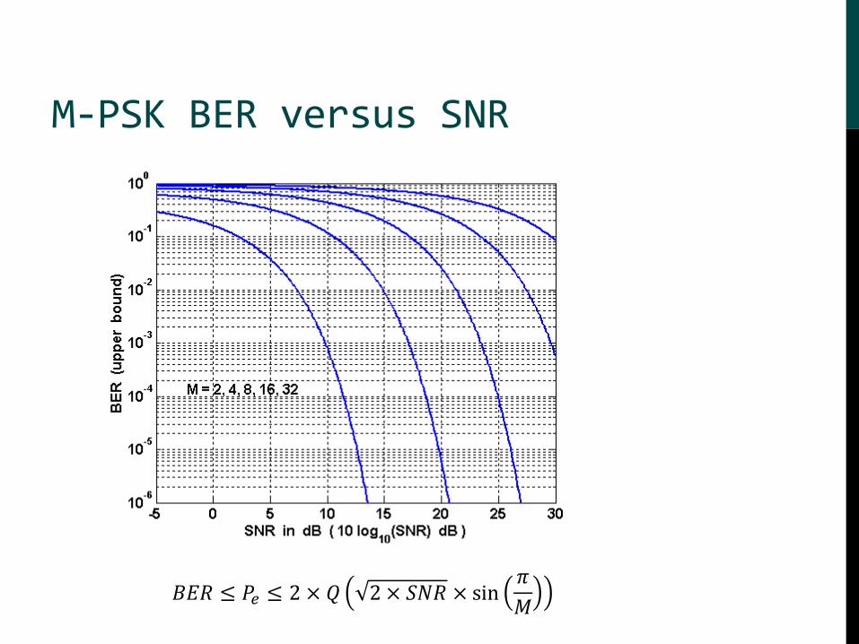
M-PSK BER versus SNR
𝐵𝐸𝑅 ≤ 𝑃𝑒 ≤ 2 × 𝑄 2 × 𝑆𝑁𝑅 × sin𝜋
𝑀