Embed Size (px)
Citation preview

Digital Barriers Elevated Temperature Screening System - Operational Manual Document Reference: DBSP-OM-ED340
Date: 17th June 2020
Issue: Issue 1v4_USA

SUPPORT PUBLICATIONS DBSP-OM-ED340
i
CONDITIONS OF RELEASE
This information is released by Digital Barriers for lawful purposes only. This information must be afforded the same degree of protection as that afforded to information of an equivalent classification originated by the recipient Government or as required by the recipient Government's National Security regulations. This information may be disclosed only within the organization of the recipient establishment, except as otherwise authorized by Digital Barriers. This information may be subject to privately owned rights.
© 2020 DIGITAL BARRIERS

DBSP-OM-ED340 SUPPORT PUBLICATIONS
ii
RECORD OF CHANGES
This is a controlled document and will be uncontrolled once issued; additional controlled copies can be obtained through the issuing authority. In the event of copying locally, including electronically, each document should be marked ‘Uncontrolled Copy’. Full issues and page amendments are identified on this page. Any proposals for change should be forwarded, in writing, to the issuing authority.
Issue Date Detail of Changes Amended by
Issue 1v1 12 May 2020 Initial Issue (Draft) Kevin Peters
Issue 1v2 19 May 2020 Rebrand of EV Gateway | System Product Code Update Kevin Peters
Issue 1v3 22 May 2020 Camera Cable Clamp Update Kevin Peters
Issue 1v4 17 Jun 2020 Update to IPL for Laptop Options Change to BB & Camera Mounts Inclusion of General Passwords
Kevin Peters

SUPPORT PUBLICATIONS DBSP-OM-ED340
iii
LIST OF CONTENTS Conditions of Release……………………………………………………………………………………………………………………i Record of Changes……………………………………………………………………………………………………………………….ii
Introduction…………………………………………………………………………………………………………………………………………..1 Illustrated Parts List……………………………………………………………………………………………………………………………….1
Overview....................................................................................................................................................................... 1 Quantities ..................................................................................................................................................................... 1 Annotations .................................................................................................................................................................. 1 Indentations ................................................................................................................................................................. 1 System Parts List ........................................................................................................................................................... 2
Physical Construction……………………………………………………………………………………………………………………………..6 Overview....................................................................................................................................................................... 6 Construct the ETS Trolley ............................................................................................................................................. 6 Mount the Dual Head Camera ...................................................................................................................................... 7 Fix the Interface Equipment Enclosure Box .................................................................................................................. 8 Deploy the Thermal BlackBody Temperature Reference ............................................................................................. 9 Connect the Equipment (Wiring) ................................................................................................................................ 10 Deployment Suggestions ............................................................................................................................................ 11
General ................................................................................................................................................................... 11 Dual Head Camera .................................................................................................................................................. 11 BlackBody Temperature Reference Sensor ............................................................................................................ 11 Typical Deployment Scenario ................................................................................................................................. 11
Operational Use……………………………………………………………………………………………………………………………………13 Overview..................................................................................................................................................................... 13 Intelligent Screening Software ................................................................................................................................... 13
Application Launch ................................................................................................................................................. 13 Basic Operational Settings ...................................................................................................................................... 14
EdgeVis Gateway ........................................................................................................................................................ 18 EV Client ..................................................................................................................................................................... 19 High Temperature Alerts ............................................................................................................................................ 21
Alarm Service Application ....................................................................................................................................... 21 EdgeVis Alarm Notification Actions ........................................................................................................................ 21
Basic Troubleshooting………………………………………………………………………………………………………………………....25 Non-Connection of Screening Software ................................................................................................................. 25 Too Frequent Temperature Alerts .......................................................................................................................... 25 Non-Connection of Remote Video Feed ................................................................................................................. 26 Non-functioning Remote Temperature Alerts........................................................................................................ 26
Contacting Support………………………………………………………………………………………………………………………………27 Raising a DB Support Ticket ........................................................................................................................................ 27
Directly via Support Portal ...................................................................................................................................... 27 Feedback Widget via Support Portal ...................................................................................................................... 27 E-mail ...................................................................................................................................................................... 28
Checking DB Ticket Status .......................................................................................................................................... 28
LIST OF FIGURES
Figure 1: Illustrated Parts List - ETS System (LRUs) Equipment (1) ............................................................................. 2 Figure 2: Illustrated Parts List - ETS System (LRUs) Equipment (2) ............................................................................... 3 Figure 3: Deployment - Suggested Deployment Layout .............................................................................................. 12 Figure 4: Deployment - BlackBody Placement .......................................................................................................... 12

DBSP-OM-ED340 SUPPORT PUBLICATIONS
iv
Figure 5: Screening Software - Launch and Connection.............................................................................................. 13 Figure 6: Screening Software - Connection Credentials .............................................................................................. 14 Figure 7: Screening Software - Successful Connection ................................................................................................ 14 Figure 8: Screening Software - Auto-Focus Selection .................................................................................................. 14 Figure 9: Screening Software - Basic Operational Settings Selection ......................................................................... 15 Figure 10: Screening Software - Change Distance Setting .......................................................................................... 15 Figure 11: Screening Software - Set BlackBody Shield Area........................................................................................ 16 Figure 12: Screening Software - Blackbody Area Administrative Password ............................................................... 17 Figure 13: Screening Software - Blackbody Area Settings Selection ........................................................................... 17 Figure 14: EV Gateway - Hidden Icons ........................................................................................................................ 18 Figure 15: EV Gateway - Application Launch .............................................................................................................. 18 Figure 16: EV Gateway - Start ..................................................................................................................................... 19 Figure 17: EV Client - Select Server ............................................................................................................................. 19 Figure 18: EV Client - Select Encoder .......................................................................................................................... 19 Figure 19: EV Client - Viewable Video Feed Screens ................................................................................................... 20 Figure 20: EV Client - Select Maps and Alerts ............................................................................................................. 20 Figure 21: EV Client - Video Stream with Maps and Alerts View ................................................................................ 21 Figure 22: Alarm Service - Shortcut ............................................................................................................................ 21 Figure 23: Alarm Service - Event Detection Launch .................................................................................................... 21 Figure 24: EV Alarm Alerts - Alert Received ................................................................................................................ 22 Figure 25: EV Alarm Alerts - Viewing Received Alerts ................................................................................................. 22 Figure 26: EV Alarm Alerts - Playback Controls .......................................................................................................... 23 Figure 27: EV Alarm Alerts - Full Resolution Location ................................................................................................. 23 Figure 28: EV Alarm Alerts - Enhance and Further Action .......................................................................................... 24 Figure 29: Support - Direct Support Request .............................................................................................................. 27 Figure 30: Support - Feedback Widget Support Request ............................................................................................ 27 Figure 31: Support - Ticket Status Check .................................................................................................................... 28
LIST OF TABLES
Table 1: Parts List - ETS System Equipment (LRUs) Parts List........................................................................................ 5 Table 2: Build - Construct the ETS Trolley ..................................................................................................................... 6 Table 3: Build - Mount the Dual Head Camera ............................................................................................................. 7 Table 4: Build - Fix the Network Enclosure Box ............................................................................................................. 8 Table 5: Build - Deploy the Thermal BlackBody Temperature Reference...................................................................... 9 Table 6: Build - Connect the Equipment (Wiring) ........................................................................................................ 10 Table 7: Screening Software - BlackBody Shield Area Instructions ............................................................................. 16

SUPPORT PUBLICATION DBSP-OM-ED340
1
INTRODUCTION
1 This Elevated Temperature Screening (ETS) System Operational Manual is intended for users to enable them to deploy a system (once having been staged and configured via Digital Barriers) into an area of need - construct and turn-on into an operational working system. It is broken down into the following:
1.1 Illustrated Parts List.
1.2 Physical Construction.
1.3 Operational Use.
1.4 Basic Troubleshooting
ILLUSTRATED PARTS LIST
Overview
2 This chapter will list the Line Replaceable Units (LRUs) - including cables - comprising the system.
Quantities
3 The figure in the “Number of” column specifies the quantity required for the LRU concerned.
Annotations
4 The following annotations are used in this publication:
4.1 NI. When appearing in the “Fig Item” column indicates that the item is not illustrated.
4.2 NP. When appearing in the Product Code or Part Number column indicates that the item may be illustrated, but is not available from stock as replacement item, i.e. it is a Non-Provisioned item.
4.3 NA. When appearing in the Product Code / Part Number column, indicates that no Product Code or Part Number has been allocated.
4.4 Ref. In the ‘Number of’ column indicates that the item is listed for reference purposes only.
Indentations
5 Items are listed in a logical assembly/disassembly order and are indented by the ‘Dot System’ in which each ‘dot’ depicts the relationship of the item to the main assembly.
MAIN ASSEMBLY Attaching parts for main assembly. . FIRST LEVEL OF BREAKDOWN (Sub-assembly or detail part of main assembly). . Attaching parts for first level. . . SECOND LEVEL OF BREAKDOWN (Sub-sub-assembly or detail part of Sub-assembly). . . Attaching parts for the second level. . . . THIRD LEVEL OF BREAKDOWN (Sub-sub-sub assembly or detail part of Sub-sub-assembly). . . . Attaching parts for third level.
DBSP-OM-ED334 SUPPORT PUBLICATION
2
System Parts List
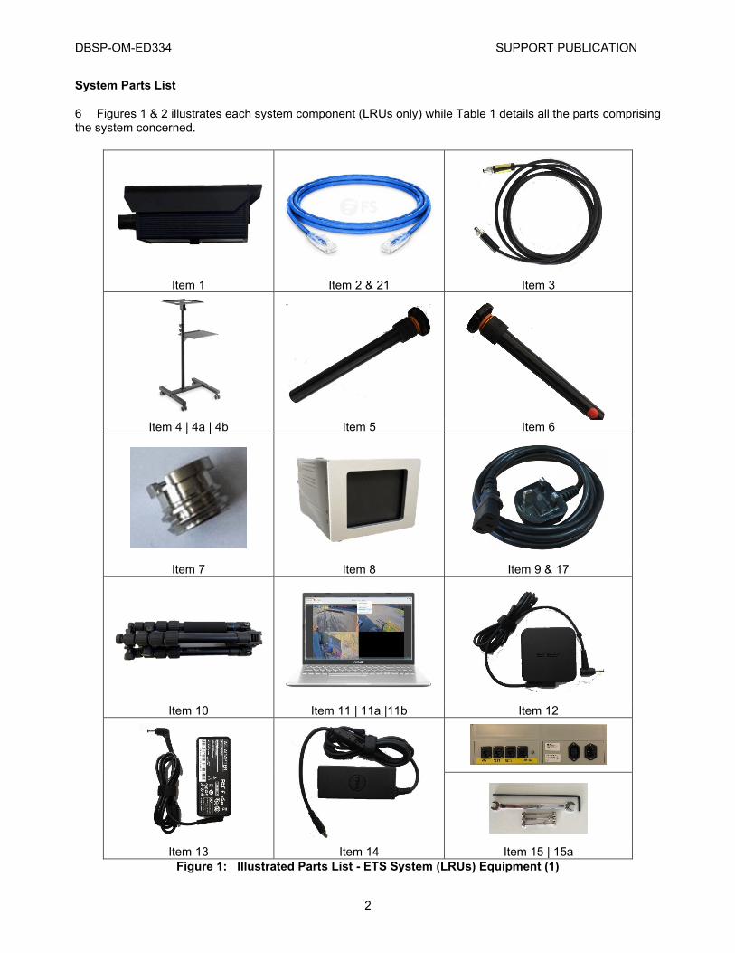
6 Figures 1 & 2 illustrates each system component (LRUs only) while Table 1 details all the parts comprising the system concerned.
Figure 1: Illustrated Parts List - ETS System (LRUs) Equipment (1)
Item 1 Item 2 & 21 Item 3
Item 4 | 4a | 4b Item 5 Item 6
Item 7 Item 8 Item 9 & 17
Item 10 Item 11 | 11a |11b Item 12
Item 13 Item 14 Item 15 | 15a

SUPPORT PUBLICATION DBSP-OM-ED340
3
Item 16 Item 18
Item 19 Item 20
Figure 2: Illustrated Parts List - ETS System (LRUs) Equipment (2)

DBSP-OM-ED340 SUPPORT PUBLICATION
4
Figure 1 Item Item Name Product Code Part No. No. of Remarks
0 ELEVATED TEMPERATURE SCREENING (ETS) SYSTEM EQUIPMENT (COMPLETE) J-09-0001-0011 TBA 1 -
1 . DUAL HEAD THERMAL/DAYLIGHT CAMERA TBA TBA 1 -
2 . CAMERA ETHERNET CABLE TBA TBA 1 -
3 . CAMERA POWER CABLE TBA TBA 1 -
4 . ETS TROLLEY TBA TBA 1 -
4a . . ETS TROLLEY LAPTOP MOUNT PLATE NA NA 1 -
4b . . ETS TROLLEY CAMERA MOUNT PLATE NA NA 1 -
5 . TRIPOD EXTENSION MOUNT (BLACKBODY) TBA TBA 2 -
6 . CAMERA EXTENSION MOUNT (TROLLEY ONLY) TBA TBA 1 -
7 . CAMERA SCREW ¼” TO ⅜” TBA TBA 1 -
8 . THERMAL BLACKBODY REFERENCE TBA TBA 1 -
9 . THERMAL BLACKBODY PSU CABLE (UK PLUG) TBA TBA 1 -
10 . BLACKBODY TRIPOD TBA TBA 1 -
11a . LAPTOP (ASUS) TBA TBA 1 -
11b (NI) . LAPTOP (LENOVO) TBA TBA 1 -
11c (NI) . LAPTOP (DELL) TBA TBA 1 -

SUPPORT PUBLICATION DBSP-DG-ED340
5
Table 1: Parts List - ETS System Equipment (LRUs) Parts List
12 . . LAPTOP PSU (ASUS) NA NA 1 -
13 . . LAPTOP PSU (LENOVO) NA NA 1 -
14 . . LAPTOP PSU (DELL) NA NA 1 -
15 . NETWORK INTERFACE BOX TBA TBA 1 -
15a . ENCLOSURE BASE FIXINGS (BOLTS / NUTS / LONG ARM ALLEN KEY / WRENCH) TBA TBA 1
PACK 3x NUT/BOLTS
1x 3MM ALLEN KEY 1x 7MM WRENCH
16 . . LAPTOP TO ENCLOSURE EXTENDER PSU CABLE (C5 TO C14) TBA TBA 1 -
17 . NETWORK INTERFACE BOX CABLE (UK PLUG) TBA TBA 1 -
18 . USB TO ETHERNET ADAPTER TBA TBA 1 -
19 . USB MEMORY STICK TBA TBA 1 -
20 . ENCLOSURE EXTENDER PSU CABLE (C14 TO C15) TBA TBA 1 -
21 . ETHERNET CABLE (3 METRE) TBA TBA 1 -

DBSP-OM-ED340 SUPPORT PUBLICATION
6
PHYSICAL CONSTRUCTION
Overview
7 This section details how to construct the equipment from scratch into a system ready for operation - ensure each step is carried out in the order shown; it is broken down into the following sub-sections:
7.1 Construct the ETS Trolley.
7.2 Mount the Dual Head Camera.
7.3 Fix the Interface Equipment Enclosure Box.
7.4 Deploy the Thermal BlackBody Temperature Reference.
7.5 Connect the Equipment (Wiring).
7.6 Deployment Suggestions.
Construct the ETS Trolley
8 TABLE 2 details how to construct the ETS trolley.
Step Description Image Guide
1 Follow the instructions as per the provided manufacturers guidelines1 N/A
Table 2: Build - Construct the ETS Trolley
1 To ease construction a Phillips PH2 Screwdriver, a 10mm Hex Socket (with associated ratchet or driver) and a Flat head Screwdriver (size 5) is advisable.

SUPPORT PUBLICATION DBSP-DG-ED340
7
Mount the Dual Head Camera
9 Table 3 details how to mount the camera.
Table 3: Build - Mount the Dual Head Camera
Step Description Image Guide
1 Locate the Camera Extension Mount marked with a Red Dot or ‘Trolley Only’.
2 Screw the top camera thread into the Camera Unit.
3 Extend the Camera Extension Mount to the required length.
4
Supplied rod extension may require installer to remove larger thread cap in order to reduce the thread to 1/4” match the ETS Trolley Mounting Screw.
5 Adjust the Camera so it is facing forwards and tighten the locking thread.
6
Attach the supplied power cable and Ethernet cable and utilizing the Cable Management system ensure the cables are clamped along the length of the trolley.

DBSP-OM-ED340 SUPPORT PUBLICATION
8
Fix the Interface Equipment Enclosure Box
10 Table 4 details how to fix the Network Enclosure Box.
Step Description Image Guide
1 Remove the lid of the Enclosure Box N/A
2 Line up the shown mounting points with the holes in the Trolley Base
3 Attach the Enclosure Box to the trolley using the provided bolts / nuts / tools.
Table 4: Build - Fix the Network Enclosure Box

SUPPORT PUBLICATION DBSP-DG-ED340
9
Deploy the Thermal BlackBody Temperature Reference
11 Table 5 details how to deploy the blackbody sensor.
Table 5: Build - Deploy the Thermal BlackBody Temperature Reference
Step Description Image Guide
1
Locate a Blackbody Tripod Extension Mount. Unscrew the tightening sprocket (discard - no longer needed) and turn the screw around (unthread then rethread the opposite way).
2 Extend both supplied mounts to the required length.
3 Fix the mount with the still attached tightening sprocket into the underside of the Black Body.
4 Fix the lower part (no sprocket) to the top of
the Tripod
5 Attach lower and upper extension mounts.
6 Adjust the BlackBody to face towards the Camera.

DBSP-OM-ED340 SUPPORT PUBLICATION
10
Connect the Equipment (Wiring)
12 Table 6 details how to connect the equipment’s wiring together.
Step Description Image Guide
1
Connect the Network Enclosure Box, Camera and Blackbody to the supplied cables.
Table 6: Build - Connect the Equipment (Wiring)

SUPPORT PUBLICATION DBSP-OM-ED340
11
Deployment Suggestions
13 The following section lists various suggestions to optimize the deployment of the ETS system; laid out as follows:
13.1 General.
13.2 Dual Head Camera.
13.3 BlackBody Temperature Reference Sensor.
13.4 Typical Deployment Scenario.
General
14 The system should be deployed indoors in a relatively stable ambient temperature.
15 Any quick changes in temperature will impact on the BlackBody’s ability to regulate its surface temperature. This will have an impact on the accuracy of the system.
16 Should there be no alternative to deploying the System outdoors, then protection from the environment - i.e. container/tent - should be implemented.
17 Avoid areas that have high temperature objects in the Camera’s FoV, if any are present, utilization of the Software’s Shielding Tool will negate their impact.
18 Avoid placing directly at an outside entrance, force personnel to walk through a channel first before screening (as shown at Figure 3). This will allow enough time to reduce the outside conditions impact of their skin temperature.
Dual Head Camera
19 The Dual Head Camera should be deployed 3 to 16 feet from the people to be screened.
20 For best performance, the camera should be approx. head-height of the people to be screened; this will minimize the angle of incidence from the camera to faces.
BlackBody Temperature Reference Sensor
21 The Black Body should be deployed towards the top of the Field of View (FoV) of the camera in an area that will not be obstructed.
22 It should also be deployed as close to the screening range as physically possible i.e. if the screening range is 12 feet the BlackBody should be deployed 12 feet away from the camera.
23 Avoid areas with high air flow. This may impact on the BlackBody’s ability to maintain its set regulated temperature.
Typical Deployment Scenario
24 Figure 1Figure 3 illustrates a suggested layout allowing optimization of the deployed system, with associated notes below that.

DBSP-OM-ED340 SUPPORT PUBLICATION
12
Figure 3: Deployment - Suggested Deployment Layout
24.1 Personnel Movement. The above deployment includes a forced channel that the individuals must walk through. This ensures a compliant pose when walking towards the camera, while also providing time for the individuals skin temperature to stabilize thereby reducing the impact of the outside environment.
24.2 Camera Placement. The Camera Guide Belt (Rail) ensures personnel cannot get too close to the cameras as any measurements closer than the desired range will not be accurate. Any measurement too far away will read lower than actual temperature - any too close will read higher, both scenarios potentially raising false alerts.
24.3 BlackBody Placement. The BlackBody should be deployed within the camera’s Field of View and at above head height - as shown at Figure 4.
Figure 4: Deployment - BlackBody Placement

SUPPORT PUBLICATION DBSP-OM-ED340
13
OPERATIONAL USE
Overview
25 The following section details the interaction required with both the Laptop and deployed remote viewing platforms (such as an iPad) for the various applications required to operational deploy the ETS System; it consists of the following software:
25.1 Intelligent Screening Software.
25.2 EdgeVis Gateway.
25.3 EV Client.
25.4 High Temperature Alerts.
Intelligent Screening Software
26 Involving the following steps:
26.1 Application Launch.
26.2 Basic Operational Settings Configuration.
Application Launch
27 Carry out the following steps to connect the application to the thermal camera:
27.1 Ensure the system is cabled correctly, the Laptop powered up and logged into.
27.2 Double-click the icon as shown at Figure 5 (left hand screenshot).
Figure 5: Screening Software - Launch and Connection
27.3 From the resulting screen, select Connect - as shown at Figure 5 (right hand screenshot).
27.4 Enter the IP Address of the thermal camera (192.168.1.101) and Password (admini) into the resulting screens - as shown at Figure 6. Further options are available as follows:
27.4.1 Remember password.
27.4.2 Automatic login.

DBSP-OM-ED340 SUPPORT PUBLICATION
14
Figure 6: Screening Software - Connection Credentials
28 If the IP Address and Password have been entered correctly the software should connect to the camera and commence operation with the screen showing as per Figure 7 - note the green Status.
Figure 7: Screening Software - Successful Connection
Basic Operational Settings
29 The following are the basic settings required for operational use:
29.1.1 Auto-Focus.
29.1.2 Set Measurement Distance.
29.1.3 Set BlackBody Shield Area.
29.1.4 Configure Blackbody.
Auto-focus
30 Once the detection area has been identified and the equipment set-up as such; click the auto-focus button - as shown at Figure 8 - this should bring the Thermal camera being utilized into focus.
Figure 8: Screening Software - Auto-Focus Selection
SUPPORT PUBLICATION DBSP-OM-ED340
15
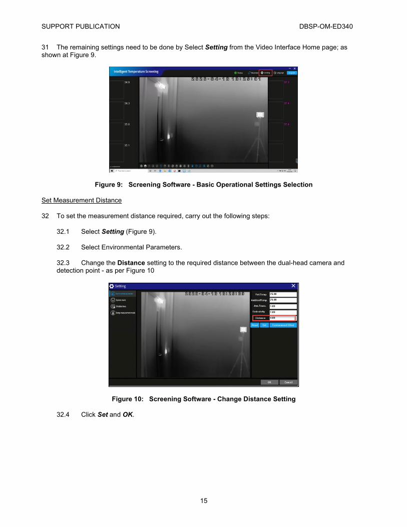
31 The remaining settings need to be done by Select Setting from the Video Interface Home page; as shown at Figure 9.
Figure 9: Screening Software - Basic Operational Settings Selection
Set Measurement Distance
32 To set the measurement distance required, carry out the following steps:
32.1 Select Setting (Figure 9).
32.2 Select Environmental Parameters.
32.3 Change the Distance setting to the required distance between the dual-head camera and detection point - as per Figure 10
Figure 10: Screening Software - Change Distance Setting
32.4 Click Set and OK.

DBSP-OM-ED340 SUPPORT PUBLICATION
16
Set BlackBody Shield Area
33 To set the BlackBody Shield area, carry out the steps as per Table 7.
Step Instructions
1 Select Setting (Figure 9).
2 Click the Shielded Area Switch icon [ ] to turn the editing function ON.
3 Click the Set Measurement Rectangle [ ] to allow an area to be created.
4 Click on an area top left of the BlackBody then release the mouse button.
5 Move the mouse to the end of the required area and click once more.
6 Click the Shielded Area Switch icon [ ] to turn the editing function OFF.
7 Select OK.
Table 7: Screening Software - BlackBody Shield Area Instructions
34 The resulting screen should resemble Figure 11.
Figure 11: Screening Software - Set BlackBody Shield Area
Blackbody Area
35 The Blackbody Area configuration settings are hidden behind an Administrator password; to unlock and configure - carry out the following steps:
35.1 Close the Setting page if a current session is open.
35.2 From the keyboard, press the following:
Ctrl > Shift > r
35.3 Enter the correct password (admin123) into the resulting window - as shown at Figure 12.

SUPPORT PUBLICATION DBSP-OM-ED340
17
Figure 12: Screening Software - Blackbody Area Administrative Password
36 After conducting the steps from Para 35, the Blackbody Area will be available from the Setting tab - as shown at Figure 13.
Figure 13: Screening Software - Blackbody Area Settings Selection
37 To configure the Blackbody correction area (with reference to Figure 13)2.
37.1 Switch on the Blackbody correction.
37.2 Tick the Draw box.
37.3 Mark the area where the Blackbody is located on the image with the annotated red rectangle, keeping the rectangle in the center of the blackbody area. The marking rectangle can be re-sized by moving the slider - recommended setting is 5. 37.4 Left click the mouse to confirm and update the coordinates in software.
37.5 Untick the Draw box.
37.6 Click Set and OK.
2 Any positional changes to either the Camera or Blackbody will necessitate the repetition of these steps.

DBSP-OM-ED340 SUPPORT PUBLICATION
18
EdgeVis Gateway
38 EdgeVis (EV) Gateway is a software solution for PCs that allows the PC desktop to be streamed via Real Time Streaming Protocol (RTSP).
39 The application is designed to start with Windows, so should need no user interaction - this can be checked by opening Hidden Icons on the Laptop to check the EV Gateway Icon is active - as shown at Figure 14;
Figure 14: EV Gateway - Hidden Icons
40 If for some reason the application fails to start with Windows carry out the following steps to launch the application.
40.1 Locate and double click the EV Gateway icon - as shown at Figure 15.
Figure 15: EV Gateway - Application Launch
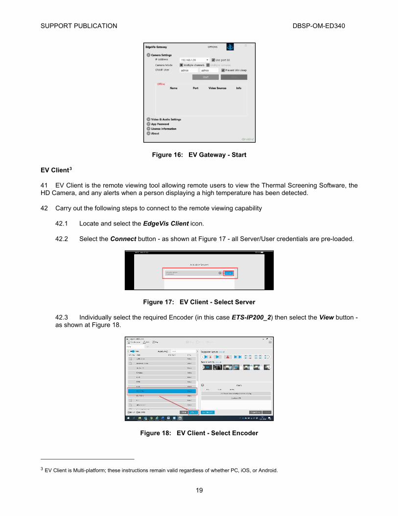
40.2 The application should launch automatically - but if not - ensure that the Start button has been selected, as per Figure 16; this will launch the application with no further user interaction necessary.
SUPPORT PUBLICATION DBSP-OM-ED340
19
Figure 16: EV Gateway - Start
EV Client3
41 EV Client is the remote viewing tool allowing remote users to view the Thermal Screening Software, the HD Camera, and any alerts when a person displaying a high temperature has been detected.
42 Carry out the following steps to connect to the remote viewing capability
42.1 Locate and select the EdgeVis Client icon.
42.2 Select the Connect button - as shown at Figure 17 - all Server/User credentials are pre-loaded.
Figure 17: EV Client - Select Server
42.3 Individually select the required Encoder (in this case ETS-IP200_2) then select the View button - as shown at Figure 18.
Figure 18: EV Client - Select Encoder
3 EV Client is Multi-platform; these instructions remain valid regardless of whether PC, iOS, or Android.

DBSP-OM-ED340 SUPPORT PUBLICATION
20
42.4 EV Client allows several views to be selected - Figure 19 shows two options with the Icon requiring selecting to allow another viewing screen to be selected shown in the left hand screenshot.
Figure 19: EV Client - Viewable Video Feed Screens
42.5 If Maps and/or Alerts are required to be displayed with the Video Streams - select Maps and Alerts as shown at Figure 20.
Figure 20: EV Client - Select Maps and Alerts
42.6 Figure 21 shows the resultant screen.

SUPPORT PUBLICATION DBSP-OM-ED340
21
Figure 21: EV Client - Video Stream with Maps and Alerts View
High Temperature Alerts
43 To allow alerts to be received from the Temperature Screening System to the remote viewing capability; the following requires user interaction:
43.1 Alarm Service Application.
43.2 EdgeVis Alarm Notification Actions.
Alarm Service Application
44 To launch the Alarm Service, carry out the following:
44.1 Locate the Alarm Service short-cut on the Laptop desktop - as shown at Figure 22:
Figure 22: Alarm Service - Shortcut
44.2 Once launched ensure that Detect Events is checked - as per Figure 23.
44.3 An additional Trigger Event Detection Event button is also available for testing purposes4.
Figure 23: Alarm Service - Event Detection Launch
EdgeVis Alarm Notification Actions
45 Once the Alarm Service has started, alerts will be received via EV Client as shown at Figure 24.
4 EdgeVis Alarm Rule requires configuration - check with System Administrator.

DBSP-OM-ED340 SUPPORT PUBLICATION
22
Figure 24: EV Alarm Alerts - Alert Received
46 All Elevated Temperature alerts will be recorded on the EV Encoder in its archive; this archive must be accessed to enable the person of interest that triggered the Elevated Temperature alert to be viewed, recognized and any resultant action to be carried out. To conduct this process, carry out the following steps (referenced at Figure 25):
46.1 Highlight the required received alert.
46.2 Navigate to the bottom left of the screen and click the View button down arrow.
46.3 Select View Archive Video.
Figure 25: EV Alarm Alerts - Viewing Received Alerts
47 This will open the archive approx. 5 seconds before the alert was received5 and play through the recorded video of the duration of the alert. Normal play-controls are available for the user to Fast Forward, Rewind and Pause at required intervals - as shown at Figure 26.
5 Dependent on EdgeVis Alarm Rule configuration; recommended at 10 second duration post-alert with 5 seconds pre-alert.

SUPPORT PUBLICATION DBSP-OM-ED340
23
Figure 26: EV Alarm Alerts - Playback Controls
48 Once the user has located the Person of Interest - the EV High Resolution tool - located as shown at Figure 27 can be employed to enhance the quality of that person.
Figure 27: EV Alarm Alerts - Full Resolution Location
49 Once the Hi-resolution tool has opened, the user can select the frame of their choice and enhance the face (if required) of the Person of Interest. Further action can then be carried out on that image by selecting Save and choosing one of the 6 further actions - as shown at Figure 28:

DBSP-OM-ED340 SUPPORT PUBLICATION
24
Figure 28: EV Alarm Alerts - Enhance and Further Action
50 Once finished with the Archive and Hi-resolution tool, both should be closed to return back to the Live Stream and if no further incidents require investigating - the Live Stream should be closed to prevent excessive Data Costs being incurred through needless Video streaming6.
6 An Inactive Viewing Timer has been set - so should anyone forget to close the stream it will automatically close.

SUPPORT PUBLICATION DBSP-OM-ED340
25
BASIC TROUBLESHOOTING
51 The following are common issues and basic troubleshooting that can be applied before raising the matter to further support:
51.1 Screening Software:
51.1.1 Non-connection of Software.
51.1.2 Too frequent Temperature alerts.
51.2 Remote Viewing Capability:
51.2.1 Non-connection of remote Video Feed.
51.2.2 Non-functioning remote Temperature alerts
Non-Connection of Screening Software
52 Carry out the following checks:
52.1 Re-power the Network Interface Box.
52.2 Check all cabling on the following items:
52.2.1 Camera.
52.2.2 Network Interface Box.
52.2.3 Laptop.
52.3 Ensure the IP Address for the Thermal Camera is correct (192.168.1.101).
52.4 Ensure the password being entered is correct.
52.5 Contact DB for support.
Too Frequent Temperature Alerts
53 Carry out the following checks:
53.1 Re-start the Screening Software application.
53.2 Check that the Distance has been set correctly in Environmental Parameters.
53.3 Check the settings have been configured correctly in BlackBody Area7.
53.4 Check the Temp-Measurement Mode settings are correct.
53.5 Contact DB for support.
7 This will need doing every time either the Blackbody or Camera are moved.

DBSP-OM-ED340 SUPPORT PUBLICATION
26
Non-Connection of Remote Video Feed
54 If neither stream is available on the Encoder; carry out the following:
54.1 Re-power the Network Interface Box.
54.2 Check the iPad is connected to either a Cellular or Wi-Fi Network.
54.3 Contact DB for support.
55 If the HD video feed is not is available on the Encoder (Blue Screen displayed) but the EV Gateway stream is still available; carry out the following:
55.1 Re-power the Dual Head Camera.
55.2 Contact DB for support.
56 If the EV Gateway video feed is not is available on the Encoder (Blue Screen displayed) but the HD video feed is still available; carry out the following:
56.1 Check the Laptop display is still showing the Thermal Screening software.
56.2 Ensure that EV Gateway is operational (check hidden icons).
56.3 Open the EV Gateway application and ensure the following:
56.3.1 The application is started.
56.3.2 The IP address of the selected feed is 192.168.1.998.
Non-functioning Remote Temperature Alerts
57 Carry out the following checks:
57.1 Refer to Para 43 and ensure that the ETS > EV Client configuration is correct.
57.2 Contact DB for support.
8 May need to restart the Laptop ensuring the USB > Ethernet adapter is inserted prior to re-start.

SUPPORT PUBLICATION DBSP-OM-ED340
27
CONTACTING SUPPORT
58 The following are various support mechanisms available to the Operational user:
58.1 Raising a DB Support Ticket.
58.2 Checking DB Ticket Status
Raising a DB Support Ticket
59 A support request can be raised with Digital Barriers in the following ways:
59.1 Directly via Support Portal.
59.2 Feedback Widget via Support Site.
59.3 E-mail.
Directly via Support Portal
60 Open a suitable web-browser and enter the following into the URL bar:
https://tvisupport.freshdesk.com/ 61 From the resulting screen enter your log-in credentials, which will result in the page being displayed as at Figure 29. Click on New Support Ticket and enter as many details as possible then click Submit.
Figure 29: Support - Direct Support Request
Feedback Widget via Support Portal
62 Open a suitable web-browser and enter the following into the URL bar:
https://tvi-support.digitalbarriers.com/ 63 From the resulting screen enter your log-in credentials, which will result in the page being displayed as at Figure 30. Click on New Support Ticket and enter as many details as possible then click Submit.
Figure 30: Support - Feedback Widget Support Request
DBSP-OM-ED340 SUPPORT PUBLICATION
28
64 A support ticket can be raised on your behalf by sending an E-mail containing as many details of the issue as possible to the following address:
[email protected] Checking DB Ticket Status
65 To check on the progress of any raised ticket; carry out the following procedure:
65.1 Open a suitable web-browser and enter the following into the URL bar:
https://tvisupport.freshdesk.com/ 66 To check on the progress of any raised ticket; carry out the following procedure:
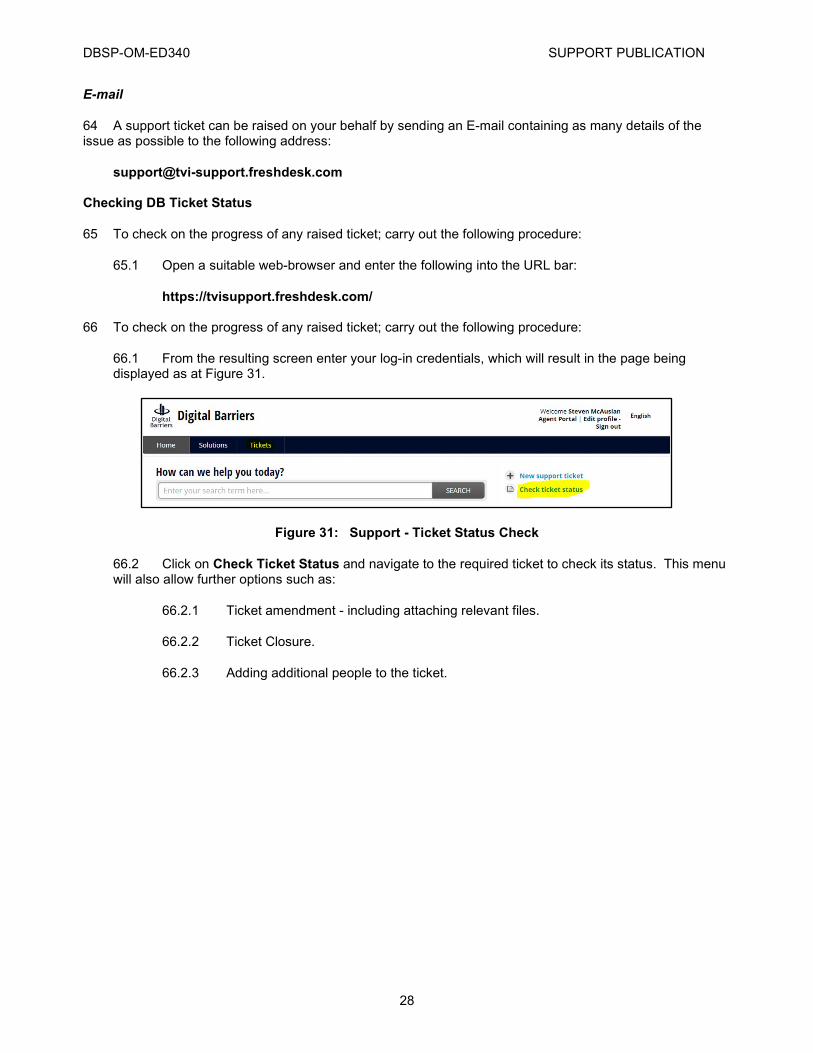
66.1 From the resulting screen enter your log-in credentials, which will result in the page being displayed as at Figure 31.
Figure 31: Support - Ticket Status Check
66.2 Click on Check Ticket Status and navigate to the required ticket to check its status. This menu will also allow further options such as:
66.2.1 Ticket amendment - including attaching relevant files.
66.2.2 Ticket Closure.
66.2.3 Adding additional people to the ticket.