Embed Size (px)
Citation preview
42 IEEE TRANSACTIONS ON RELIABILITY June
DIGITAL CIRCUIT REDUNDANCY
REIN TEOSTE, Member, IEEE
Summary-While some original work is pre- pers have described theoretical studies of re-
sented, this paper is mainly of the nature of dundancy models; however, occasionally somesurvey of redundancy techniques to date. Several hardware has been built to demonstrate the ideas.redundancy techniques are described in il with Usually, new redundancy schemes are describedmathematical models for estimating reliability imr- in the form of proposals with only theoreticalprovement. The methods ae compared on the basis estimates of reliability improvement.of reliability improvemen bnd general comments The application of redundancy has been quiteare made about applicatiofs. The reliability equa- scarce. Occasionally, even before the work oftions for Moore-Shannon, majority, gate connector, Moore, Shannon, and Von Neumann, paralleland other redundancies, show that Moore-Shannon circuits have been used. More sophisticatedtype of redun ncy provides the best reliability designs are presently filtering into the equip-improvement An example of a Moore-Shannon ment design. In some instances, standard re-
redundant flip-flop haK arge reliability dundant components have been suggested forimprovements eo tamne by applying redun- more advanced reliable logical equipment.dancy to only the less reliable components, thus The use of redundancy implies that the redun-keeping the amount of redundancy to a minimum. dant equipment costs more. The cost is not only
8 -0vt e the dollar cost but cost in additional weight, size,6Xan-' power consumption, and maintenance. In some
INTRODUCTION applications, particularly in satellite use, weight,'7,,2>> f . volume and power consumption are more im-In 1/56, two articles appeared, launching a portant than the monetary cost itself. On the other
large effort in redundancy studies. Moore and hand, in such applications, maintenance does not
Shannon of Bell Telephone Laboratories were cause difficulty since maintenance is usually notmainly interested in improving the reliability of possible. In applications where maintenance is
the telephone switching circuits which, at the time, possible, the redundant equipment would be ex-
contained mostly relays. Hence, their classic pa- pected to have more failed components per unitper [18] discusses how the reliability of relays could time even though the equipment itself does not
be improved by connecting the coils of the relays fail, requiring considerably more maintenance.in parallel and connecting the corresponding con- What then is obtained by the additional cost?tacts of the relays in parallel series circuits in a One expects to get more reliable equipment,fashion that would enhance the reliability. Von either by an increase in the mean time to failureNeumann, in his classic paper [ 32], was con- or a higher probability of completing the missioncerned with more general digital circuits. He without equipment failure. The increase in costdiscussed the redundant design of logical circuits must be weighed off by the gains received in re-
by use of majority gates and sheffer strokes. liability in such a fashion that the over-all costWhile the synthesized components were very dif- is minimized. In order to do this, one mustferent in these two papers, the analysis was quite know exactly what is gained in reliability by A
similar and the results were very much the same, int ducing redundancy.namely, that large reliability improvements could The redundancy techniques are based on thebe obtained by use of redundancy. assumption that failures of components are
Since these two articles, many papers which statistically independent. This is a very im-describe the design of redundant circuitry have
Qportant point, because the redundancy techniques
appeared in scientific journals. Most of the pa- provide no protection if failures depend on some
common disturbance For instance, if a particular|cirrcuit is temperature dependent and fails if the
Manuscript received June 10, 1963. .r
XThe author is with the M. I. T. Lincoln Laboratory, Lex- temperature exceeds a certain value, manly cir-
ington, Mass., which is operated with support from cuits of the sam-e type will be just as unreliablethe U. S. Air Force. as a single circuit, once the maximum tempera-

1964 TEOSTE: DIGITAL CIRCUIT REDUNDANCY 43
ture is exceeded. All design deficiences fall into posed (for instance, Kilmer's machine [13]) whichthis category. One must not be misled into be- are capable of correcting transient failures only.lieving that redundancy will correct all failures Redundancy techniques are most applicable toof the equipment. In fact, the solid-state com- f &igital equipment. In analog equipment, all valuesponents of today are so reliable that most of th of signal amplitude are permissible. If a failureearlier failures are usually blamed on some occurs in analog equipment and we detect the fail-design deficiency. ure, we do not know the value of the correct output
Increasing reliability by increasing the numbe and it is difficult to construct a mechanism whichof components in the circuitry seems contrary to will detect the failure and substitute the correctthe usual method of increasing reliability. As we value for the output. Since the analog type redun-will see later, if the redundancy is applied to the dancy has not been investigated extensively, weover-all machine, and the machine reliability is will assume that only digital redundancy is ofquite poor, the application of redundancy, indeed, interest. The reliability models that follow aredecreases the reliability. In order to take advan- derived for digital circuitry.tage of the reliability improvement of the redun-dancy techniques, the redundancy must be appliedat a low component level. Majority Redundancy
Many methods of redundancy have been sug-gested. In the following sections several methods In 1956, Von Neumann [32] suggested the use ofare described and the equations which estimate three identical binary units in parallel with theirthe reliability improvement are derived. These inputs connected together and the outputs fed into amethods are by no means all the methods sug- majority organ. The majority organ is a devicegested so far, but they do form a representative which generates for its output, the input that thegroup of what has been proposed. The reliability majority of the units computed. Since we are deal-improvements of the methods are compared to ing with binary information, one of the units can faileach other and some general comments are made while the redundant system still functions properly.about applications. An obvious extension of this method is to use a
greater number of units in parallel. If N units areused, the majority organ must produce the output
REDUNDANCY TECHNIQUES which the majority of the units calculated; other-wise, the operation of the circuit is similar to the
This section describes several techniques of three-times-redundant circuit. N, of course, mustredundancy and derives the reliability improve- be an odd integer; otherwise, no majority exists.ment equations of the more concrete methods. Let us consider the problem of making an unre-
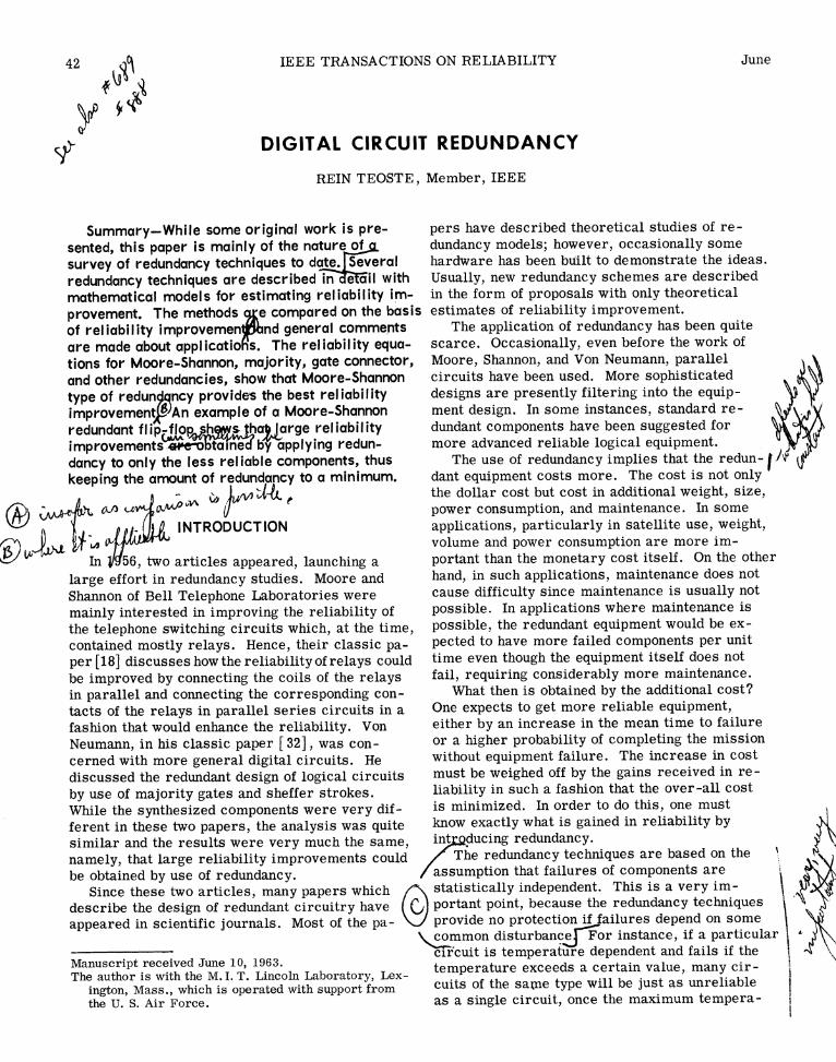
When calculating the reliability improvement liable machine more reliable by use of majorityof redundant circuitry, the nature of the failures redundancy. Suppose we can divide the machineis important. Failures can be classified as cata- into M statistically independent units of equal re-strophic and noncatastrophic. If the performance liability, so that the machine fails whenever one ofof a component degrades gradually, redundancy the M units fails. Now we apply redundancy to themay or may not increase the probability of suc- M parts of the machine, as shown in Fig. 1. Thecessful operation of the equipment, depending on rectangular blocks represent some logical functionthe nature of the degradation and whether the circuits and the round symbols represent the 4degradation is common to all components or af- majority organs.fects only an isolated component in the redundant The reliability of the nonredundant system Rocircuitry. The catastrophic failures are usually would then be the product of all the individual func- ¢more severe and the redundancy techniques are tion block reliabilities. Since the blocks were as-designed to correct catastrophic failures. "d sumed to be of equal reliability, the individual
Failures can also be classified as transient block reliability r is given byfailures, failures which occur from time to timeas the result of some temporary malfunction of 1the circuit, and permanent failures, failures Mwhose occurrence is characterized by the cir- r R0 (1)cuit making the mistake over and over again.Almost all circuit redundancy methods work for Now, suppose the majority organ is failure free buttransient failures, while methods have been pro- the redundant function boxes have equal failure prob-
44 IEEE TRANSACTIONS ON RELIABILITY June
1 3 M
~ _
2
-F2 -N{ }F NON-REDUNDANT CIRCUIT
Fig. 1-Majority redundancy applied on the Mth level.
ability (l-r). The probability that exactly n inputs states. For this case,to the majority organ are in error is given by
P(n) = (N) (lr)n(r)N-n (2) 0N(r) = n(1rl , (4)n ~ ~ ~~~~~~~~~~~~nN+l
n 2
The probability that the inputs have an incorrect for ocombination depends on how many units failed in the dd N only. (As we talk about the majority re-dundanvfiueooaiiv rmhr nwzero state and how many failed in the one state. If anc failure probability,o h
mean the upper bound of the failure probability.)all the units fail in either the zero state or the one T. . . ~~~~~~~Theredundant block will then survive if thestate, the probability that the inputs have an incor-
rect combination is equal to the probability thatH
,
majority organ and its inputs jointly survive.more than half the units failed. On the other hand, Hen iftheprob ability of themajorityif some of the units fail in the zero state and some
redundant block is given byin the one state, we can have more than half theunits fail and still get correct results. R = (1-E)[1-0 (r)]i J R = (1-6) [ 1-0 (r)] ~~~~~~~~~~~~~~~~~~~~~~(5)lhe lower bound for the error occurs when as Nmany units fail in one state as in zero state. Inthis case, all the units must fail in order for and the reliability of the over-all redundant systemthe inputs to the majority organ to be in such a iscombination that an incorrect result is obtained. M MIn this case the probability of incorrect inputs is RR = (1-E) [l-0N(r)] (6)
N /N n N-n N Substituting (4) and (1) into (6) and observing thatON(r) = I n2(l-r) r = (l-r) . (3) l-0(l-r) = 0(r),
n=N nM
N n / -E\Usually, however, we are interested in the up- R 1(cF) - _ (7)
all the units fail permanently in one of the binary n
1964 TEOSTE: DIGITAL CIRCUIT REDUNDANCY 45
1.o always limited by the term (1- E). As e increases,For0.8, E 0.0I the upper bound of reliability decreases and, at
0.8-\ / / some value of E, the reliability of the redundantmj \ / /system is always less than Ro. Von Neumann[32]
calculates this value of E for transient failures ando \ d finds it to be equal to 0.167 for N = 3. It is easy to
show [29] that the value of maximum E for perma-cr 0.4 / \ /nent failure is 0.12 5 for N = 3. It is interesting to
< Fo 0.8, E0CO Fo0O, E0.01 note that this maximum allowable value of E for' 0.2- A ~~~~~~~reliability improvement is also lower for perma-
IL / \nent failures at greater values of N.
O 15 At this point, one wonders what the value of EZ ° °0100 000 actually is. One way of building a majority organM- COMPONENT ORGANIZATION LEVEL is to build a logical circuit which will compute the
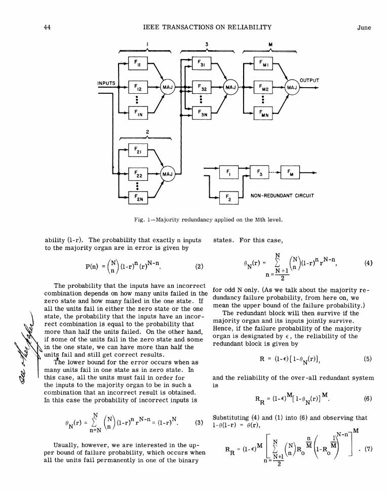
majority function. This requires many (9 for two-Fig. 2-Optimum value of M for two-out-of-three out-of-three circuit) transistors, diodes, etc.,
majority redundancy. which contribute to the failure probability of themajority device. An alternative way of building
Eq. (7) gives the reliability of the redundant a majority organ is to add all the signals and callmachine (RR) for a machine which would have a the result one if the sum of the signals exceeds areliability Ro in the nonredundant configuration. certain level. This method of majority calculationThe machine has been divided into M parts which is particularly suitable for some types of compo-are made N times redundant by the majority re- nents and has been used very successfully in coredundancy. The failure probability of the connect- circuitry [4]. Strictly speaking, this averaginging majority organ is E. procedure is not a majority calculation, since the
There are two parameters that one can select input signals are actually analog voltages and theirin (7). The amount of redundancy, N, can be chosen amplitudes are not exactly equal for the same binaryby the designer. Even though the reliability in- level. The function of the majority organ is carriedcreases as the value of N is increased, the economic out by such a circuit, and in some cases, even betterconsiderations usually limit the value of N to small than a true quorum organ could do [7].odd integers, and, in practice, N=3 has been usedalmost exclusively.
The other parameter M actually has a theo-retically optimum value. What this value is de- Modified Majority Redundancypends on the relative values of e and Ro and alsoon the criterion which is used for optimum relia- Pierce [23] suggests a modification to majoritybility. Fig. 2 shows a plot of the failure probabil- redundancy, i.e., that the different inputs to theity as a function of M. In this specific example, majority organ be weighted by the probability thatRo= 0.2 and E = 0.01. This curve is made up of they are correct. When we assume permanenttwo parts, which are shown on the figure. In the failures, the output of a unit is permanently incor-low M region, the failure probability is caused rect once the unit fails, and our weighting functionmainly by the unreliable function boxes while, for can be a discontinuous function equal to unity whenhigh values of M, there are so many majority or- the unit is operating properly and equal to zerogans that their failures will make the redundant when the unit has failed. This scheme requires thecomputer fail. ability to detect a failed unit. The detection problem
In general, the values of Ro and e are different may be a complicated task if we require that thefor different mission lengths. The constant values system must operate properly until the last unitof Ro and E, and hence, the optimum values of M, fails. By comparing the output of each unit to theare true for one mission length only. Then obvi- output of the majority organ, we can detect the fail-ously, when the mission length of a particular ure of a unit and exclude it from the majority cal-piece of equipment changes from time to time, culation. Since the output of the majority organthe optimum value of M must be based on some must always be correct, the best that one can dodifferent criteria such as the maximum mean time by this procedure is to have the redundant systemto failure. operating until all but two units fail. We shall in-
Let us select M = 1; that is, apply redundancy to vestigate the reliability improvement of such athe whole computer. We see that the reliability is system.

46 IEEE TRANSACTIONS ON RELIABILITY June
LOW PASS treated as though one of the components in the unitFILTER had failed, and since the modified majority redun-
F + \ dancy is optimally used at a high component or-
ganization level the relay failure probability isFILTER OUTPUT small as compared to the unit failure probability
and can be neglected. The relay failures to short,LowPASS1 [T /however, are more serious. In order to includeF LTER these failures in the computations, one must com-
pute the failure probability of the redundant circuitFN-' t for the case when m relay contacts short and then
INPUTS_ OUTPUTF1[ 3 average over all m. While this is straightforward
to theorize, the actual equations turn out to bepolynomials of two variables, both variables to the
Fig. 3-Modified majority redundancy. Nth order. In order to simplify calculations, therelay failures will be assumed nonexistent. When
Fig. 3 shows the schematic of the modified this assumption is made, the reliability equationmajority redundancy. The majority organ inputs for the redundant circuit can be calculated similar-are fed through relay contacts which are shown ly to the majority redundancy calculations:for illustrating purposes only. Relays, in general,would not be suitable for this function. When a R = (l-E) (1-ON), (10)failure occurs in one of the units, the normallyclosed relay will disconnect the unit from the where E is the majority organ failure probabilitymajority organ. The filtering is required to pre- which may be adjusted to compensate partly for thevent a stray error to operate the relay. The relay failures.majority organ for this purpose must be able to yFollowing the procedure of making the computertake the majority of the remaining units as the redundant on the Mth level, we obtain the equationfailed units are disconnected.f e l
If we assume that failures are statisticallyindependent and each unit 'has equal failure prob- N-1ability (l-r), the probability that n units fail is F (again given by the binomial distribution RR = (l-e) 1-N l-RoM
P(n) =(N)(l-r)nrNn. (8) 1
The probability that the inputs to the majority + (N-l) l-RO )NjM (11)organ are such that an incorrect majority organoutput is obtained, will be the sum of these terms' ~~~~~~~~whereM is the component organization level ofwhen n = N and n = N-l; thus redundancy.
Comparing (7) and (11), we see that for N=3,0 (1-r) r+ (1-r) the two equations are identical and nothing is to be
gained by using modified majority redundancy. For
Nl1 N larger values of N, however, the modified majority= N (l-r) -(N-l) (l-r) . (9) redundancy gives a higher reliability for the same
value of M. Consequently, the optimum value of MCalculating the failure probability of the com- is smaller for the modified majority redundancy.
plete redundant circuit, including majority organand relay failures, becomes quite a task. The re-sults depend greatly on the type of failures we get Moore-Shannon Redundancyin the relays. If the relays fail in the open state,they act as though one of the units had failed. If Moore and Shannon [18] have proposed connect-the relay fails in the shorted state, the output of ing the contacts of relays, with their coils con-the unit associated with the failed relay is always nected in parallel, in series parallel circuits inused for the majority computation, whether it is such a manner that the resulting circuit acts ex-right or wrong. The open contact failures can be actly like a single relay. They have shown that

1964 TEOSTE: DIGITAL CIRCUIT REDUNDANCY 47
can calculate a failure probability F1 for the cir-cuit, which is the probability that the circuit isclosed when it should be open, and a failure prob-ability F2, which is the probability that the circuitis open when it should be closed.
When we have Type 1 failures, the failure of thecircuit of Fig. 4(a) occurs only when the circuit
S should be open. The circuit will be closed if Si and(a) S2 or S3 and S4 short. The probability that S1 and
S2 short is p2, and the probability that the circuitwill be closed is
F1 =1 -(1p2) = 2p2 --p4 (12)
When we have Type 2 failures, the failure of thecircuit of Fig. 4(a) occurs only when the circuitshould be closed. The circuit will be open if both
(b) of the parallel branches are open. The Si, S2branch will be open if S1 or S2 is open. So, theprobability that this branch is open is 1 -- (l-p)2,and the probability that the complete circuit is
Fig. 4-Moore-Shannon redundancy. (a) Four times open is pl
redundant switch circuit. (b) Dual of cir- o i
cuit shown in (a).
arbitrarily reliable relays can be built from F2 = [l(lp)] =4p2--4p +p4. (13)arbitrarily poor relays, provided enough of thepoor ones are used in the circuit. With little mod- The circuit failure depends on which failures areification, this type of redundancy can be applied to more likely and what the logical function of the cir-other switch-like components. cuit is. If we knew what per cent of the time the
Fig. 4 shows two simple circuits out of the many circuit should be closed or open, we could averagepossible combinations of series parallel circuits. the failure probability over these conditions. Since jIt is easy to see that any one of the switches short- the circuit opens and closes in accordance with theing or staying open does not affect the operation of logical operations performed, which we do not know,the circuit. Since one of these circuits is the dual we can assume that the circuit is always in theof the other, the reliability equations of the two state that yields the highest failure probability. If /circuits are related. the failure probability for the two types of failures
The reliability calculations for the circuits of is numerically equal, we can easily show thatFig. 4 have been made for both transient failures F1 < F2 for all values of switch failure probabili-[18] and permanent failures [8] in previous litera- ties. Let p represent the greater of Type 1 orture. Here we will derive the equations for system Type 2 failures, and let F be the upper bound ofreliability so that we can compare this method with failure probability of the redundant circuit; thenthe others.
There are two possible types of failure associ- F = F= 4p2 _4p3 + p4 (14)ated with a switch: 2
Type 1) The switch is closed when it should be which will be used as the failure probability of theopen. redundant circuit.
Type 2) The switch is open when it should be If we have a machine which contains K switch-closed. like circuits, we can make each circuit more re-
Let us designate the probability of occurrence liable by Moore-Shannon redundancy. If theof Type 1 failures by p1 and Type 2 failures by P2, nonredundant machine has a reliability of Ro, theand assume that failures of the different switches 1in the same circuit occur with equal probability single switch reliability will be R0K . This as-and are statistically independent events. Then we sumes equal switch reliabilities and statistical

48 IEEE TRANSACTIONS ON RELIABILITY June
independence. By noting that the reliability is one vided any means for correcting such failures.minus the failure probability, we can calculate the Eq. (15), however, corresponds to a circuit whichredundant switch reliability by (14), and the redun- corrects both open and shorting failures.dant system reliability is the redundant circuitreliability raised to the Kth power. Thus,
K Gate Connector Redundancy2 4]
R = 2R K --R K1* (15) The majority redundancy is a convenient way toR o o make any binary circuit more reliable; however,
the failure probability of the redundant circuit al-Since the circuit of Fig. 4(b) is the dual of the ways being greater than the failure probability of
circuit of Fig. 4(a), the failure probability equa- the connecting majority organ is a disadvantage.tions are reversed for the two circuits. The fail- Consequently, if redundancy is applied at a lowure probability equations would be given by (12) component organization level, the majority organand (13) with F1 replaced by F2 and P1 replaced failure probability contributes greatly to the over-by P2 and vice versa. The upper bound of the fail- all computer failure probability. On the other hand,ure probability, (14), stays the same, and (15) with perfect majority organs, the best improvementholds for both circuits. However, when one type in reliability is obtained when redundancy is ap-of failure is more likely than the other, better plied at a low component organization level.results will be obtained by selecting one of the Moore-Shannon redundancy does not have thecircuits. above limitation, but the method is only applicable
A commonly used redundancy is a special case to switch-like components. Any circuits withof the Moore-Shannon redundancy. If one never critical component values are not easily madeexpects any shorting-type failures, several con- more reliable by Moore-Shannon type of redundancy.tacts in parallel will provide much better relia- The gate connector redundancy is one method ofbility improvement. A similar situation holds overcoming both of these difficulties. It is a com-when one never expects any open failures, then bination of the two redundancies, several binaryseveral contacts can be placed in series to en- circuits being connected in parallel and the con-hance reliability. The reliability of n units in necting majority organ being replaced by a circuitparallel is given by of switch-like gates. The circuit of switch-like
n gates, the gate connector, contains no components1P2 ' whose failure would make the redundant circuit
fail. All component failures in the gate connectorwhere P2 is the probability of the contacts failing act as though the failures were in binary units.in the open condition. The probability of the con- Fig. 5 shows the gate connector redundancy ap-tacts shorting is assumed to vanish. The over-all plied to four units in parallel and a four elementsystem reliability then becomes hammock network for the gate connector. By in-
spection, one can see that single failures are
l -K corrected in such a circuit. The gate circuits_ \ n are similar to the Moore-Shannon circuits and
RR = -- , (16) the idea can be extended to any number of parallelunits by using higher number of gates in the gateconnector, as explained by Moore and Shannon [18].
where RR and Ro are defined as previously, and K Let us define f and g as the probabilities of fail-again is the number of contacts in the over-all non- ure for the binary unit and gate, respectively.redundant device. A similar equation is obtained Again we assume that all f are equal and all g arefor the case when the contacts are placed in series equal, and failures are statistically independent.and open failures are assumed to be nonexistent. Referring to Fig. 5(a), the output with Type 1
An interesting observation about (16) is that the failures should be zero, but may be, mistakenly,redundant equipment reliability is always greater one. The output of G, will be one if unit 1 fails,than the nonredundant equipment reliability, where- G1 fails or both fail. The probability of this eventas (15) shows that, for some values of R0o the re- taking place isdundant equipment is less reliable than thenonredundant equipment. This apparent advantage 1 -(1-f 1) (l-g1),is present because we have not allowed shorting-type failures, and consequently, we have not pro-

1964 TEOSTE: DIGITAL CIRCUIT REDUNDANCY 49
ONE INPUT OUTPUTINPUTS OUTPUT
F
F1 G1; k CONTROL
INPUTS|U GATE FAILURES ARE ASSUMEDFL GI< TO INCLUDE SHORTS BETWEEN
F '_ 04 CONTROL AND OUTPUT.(a) g OUTPUT
Fig. 6-Gate.
ONE
INPUTS OUTPUTand the probability of failure of the circuit of Fig.0 5(a) due to Type 1 failures is
INPUTF F1 = 1-{1-[ 1-(l-f )(l-c)] 2
4 4 ~~~~~~~~~~~~~~~~~~~~~~~(17)(b) g OUTPUT 1)(1-11)f (1
The failure probability for Type 2 failures willFig. 5-(a) Gate connector redundancy. (b) Dual of turn out simpler. When the output should be one
circuit shown in (a). and the failures make it zero, the extra term doesnot appear and the equation for Type 2 failures is
where the subscript 1 designates Type 1 failures. simplyWhen a one is received from G1, a one will be 22transmitted to the output if unit 2 fails, G2 fails, F2 = {1--[(l-f)(l-g2)] } (18)or both fail. So, the probability of getting a one 2 2in the left channel is
If we assume that f1 = f2 and gl g2, we cannot-lf) (_gl)*12 show that one of the expressions (17) or (18) is
greater than the other for all values of f and g. Butin the region of values of f and g where reliability
Now we must investigate what happens when a improvement is obtained, F2 > F1. Let F be thezero is at the output of G1 and both unit 2 and G2 upper bound of failure probability for the redundantfail. Whether we get a failure or not depends on circuit, and let f and g be the greater of the Type 1how the gate circuit fails. Fig. 6 shows a gate unit or Type 2 failure probabilities. Then, in the regionwith leads labeled control, input, and output. In the where reliability improvement is obtained,gate connector circuit, the control is connected tothe output of the binary unit, and the input and out- 22put connections are used in the connector circuit. F = {l-[(9-f)(l-g)]}(The gate input is electrically connected to the out-put only if a one is present on the control. Now, if If we have a nonredundant system with reliabilitywe assume that we can only get a one from the out- Rtand we divide it into M statistically independentput when a one is present in the input, the circuit parts of equal reliability, the Mth part of the com-will not fail when G2 has a zero on the input and puter would have a reliability equal to the Mth rootunit 2 and G2 fail. However, if we assume that the of %o The reliability of the Mth part of the non-gate unit fails in a shorted condition in such a way redundant machine corresponds to (1-f) in ourthat a one is obtained at the output when a zero is equations. Thus,on the input and a one is on the control element,the circuit will fail if unit 2 and G2 fail. This
m
latter case will be assumed, and when this is taken (l-p) = R (20)into account, the probability of failure for one chan- 0
nel becomes2 ~~~~~~~Thereliability of the redundant system is the relia-
[1- (1-f1) (l-g1)]2 + (1-f1) (l-g1)f1g1, bility of one redundant unit raised to the Mth power.

50 IEEE TRANSACTIONS ON RELIABILITY June
This gives an equation for reliability: same number of restoring organs. This allows allM computed variables to be transmitted over a bundle
2 2 of lines. The restoring organs operate on thisRR 1 _1--(l-)2 R M (21) bundle of lines and increase the number of linesRR~ fL\~/ 0 that carry ones when there were more ones than
zeros present on the input bundle, and they de-There again exists an optimum value of M as in crease the number of ones when there were more
the majority redundancy. However, it can be shown zeros than ones present on the input bundle.that in the region of g and Ro where reliability im- Different restoring organs have been proposedprovement is obtained, the maximum value of M [16], but the most common one is the majorityshould be used. In practice, it is difficult to use organ. Fig. 7(a) and (b) illustrates this idea forsingle active element circuits as independent cir- a system of three-times duplication. The restor-cuits. A reasonable independent block in a system ing organs in this case are simple two-out-of-would consist of two active elements. Such circuits three majority organs.would include flip-flops, clock generators, two-way Fig. 7(a) shows a typical logical circuit whichlogical circuits, and so forth. has been divided into four individual logical func-
If we have a machine which consists of K active tions. Fig. 7(b) shows the same circuit, multi-element circuits, we would make M = K/2. A gate plexed. We triplicate the circuitry for eachis assumed to be equivalent to one active element function block, then use three majority gates tocircuit. When this is substituted into (21), we have get three outputs which should carry the same
function. Clearly, if one of the triplicated func-6 12 K tion blocks fails, the majority gates will correct
R= 2RK R Kj (22) the output so that we have identical outputs at theR Lo o i output side of the majority gates. On the other
hand, if the function blocks operate properly andSince the gate connector redundancy can be ap- one of the majority gates fails, the input to only
plied at low component organization level, it would one of the following function blocks will be incor-be suitable for using in conjunction with the Moore- rect and its output will be corrected by the majorityShannon redundancy. Critical components which gates following that stage of the function blocks.require better than ±50 per cent component value In Fig. 7(a) we see that function block F3 hastolerances can be made redundant by the gate con- two outputs. In such a case, we must use a set ofnector redundancy in a machine which is made majority gates at each of the outputs. If one outputredundant by Moore-Shannon redundancy. goes to several different block3, we have a choice
of either using a single set of majority gates orusing one set for each input.
Multiple Line Circuits A problem obviously arises at the very end ofthe system where all the inputs have been operated
The methods of redundancy discussed up to now on and some sort of suitable output is required.carry information over one line at specific places Usually we are not accustomed to selecting two-in the circuit. This single line is then connected to out-of-three outputs. If only one indicator must beseveral stages that follow. Such single line cir- used, its failure can cause a system failure, and ancuitry may be undesirable in some applications. additional majority organ would not concern us. InFor instance, if a continuous operation is required, general, however, we can do all the computationsshorting one of these lines will obviously cause in triplicated redundant circuitry, and a few outputequipment failure. If the machine must be opera- devices that are required for the final output couldtive while it is being repaired, parallel paths must be triplicated so that an error is easily detected byexist for the information. conventional observation.
Several methods of multiple line logic have been Computing the reliability for multiple line cir-proposed. The most common method, called multi- cuits is quite difficult, since the failure of theplexing, was proposed by Von Neumann[32] and, over-all circuit is dependent on several failuresindeed, most of the multiple line redundancies which occur in the vicinity of each other. Usuallywhich have been proposed bear some resemblance one assumes that the equipment contains failedto this multiplexing method. components, but the errors caused by these failures
The general idea in Von Neumann's multiplexing are corrected at some later place in the logicalscheme is to have many identical units operate circuitry. Because of this dependence, the over-allsimultaneously on the same inputs and have the system cannot be divided into convenient indepen-

1964 TEOSTE: DIGITAL CIRCUIT REDUNDANCY 51
INPUTF (Fl F 1F3)
INPUT 23 ''
F 42 (F3 F)
F
INPUT2 2NPUT 2 33
Fig. 7-Multiplexing by use of majority restoring organs. (a) Nonredundant circuit. (b) Redundant circuit.
dent units. The calculation of reliability of a system portant to the operation of the method, and themade redundant by multiplexing is beyond the scope method of pairing will depend on the logical functionof the present work. A treatment of the calculation of the circuit. Tryon [31] presents some rules ofof the reliability improvement is given by Von pairing which must be used for different types ofNeumann in his original article, and the reliability circuits.of the three-times redundant circuitry of Fig. 7 Suppose the nonredundant circuit of Fig. 8(a)has been calculated for a system where the failures has inputs D = 1 and E = 1, and the output of ANDare continuously monitored and repaired [28] . gate b is zero. These inputs should yield a one for
Tryon[31] has suggested a multiple line logic the output of c. The redundant circuit of Fig. 8(b)which combines the restoring function with the should then have Di = 1, Ei = 1 and outputs of bi=0logical computations, and he describes in detail which yields an output of c1 = 1. Suppose a failurethe method of using quadded circuitry. Here we has occurred in the Di input, so that D1 = 0 and thewill present a sample which demonstrates the remaining Di = 1. This failure produces a zero inprinciples behind the method. the outputs of a1 and a2, while a3 and a4 produce
Fig. 8(a) shows a logical nonredundant circuit. the correct outputs of ones. By examining the out-Fig. 8(b) shows the same logical circuit which is puts of ci we see that the output of all c1 = 1, whichquadded. All variables are transmitted over four is the correct result. The failure was correctedlines, and all logical circuits are replaced by logi- because the pairing between the circuits wascal circuits which have twice the inputs. The out- changed.put of each of the logical elements is split and fed We can see that if c had been an AND circuit,into two of the following logical elements as shown the failure would have caused all of the outputs ofin Fig. 8(b). The outputs of two of the logical cir- c1 to be incorrect (assuming that now the output ofcuits are fed into the inputs of two of the following b was a one). Because of this, the pairing shouldlogical circuits. This pairing of the outputs is im- be the same when two circuits of the same type

52 IEEE TRANSACTIONS ON RELIABILITY June
Di D2 D3 D4 ElI E2 E3 E4
Fig. 8-Quadded circuitry: Tryon's method. (a) Nonredundant circuit. (b) Quadded circuit.
follow each other, and it should change when the such chains, the error correcting cannot be donecircuit changes from an AND to O)R or OR to AND. simultaneously with operation. Separate restoringIf circuits of the same type follow each other, the circuits must be used to correct failures which re-failures will not be corrected until a different cir- duce the quadded circuitry to a special case of Voncuit is reached . In general, all failures of zeros Neumann multiplexing with four lines in a bundle.are corrected at OR circuits, and all failures of Since failures in different logical circuits areones are corrected at AND circuits. corrected differently, it is quite difficult to de-
All logical circuits can be built by the use of termine the failure probability of a quadded sys -AND, OR, and NOT circuits. Unfortunately, NOT tem. The whole system acts as one unit whichcircuits do not have the error correcting properties corrects single failures. If more than one failurefound in AND and OR circuits. However, NOT cir- occurs, where these failures occur is very im-cuits can easily be used in quadded circuitry by portant. Usually failures are corrected within aplacing a single NOT circuit in each of the four few circuits from the failure; however, one canlines. Since now, ones are changed to zeros and conceive of a case where a failure in the begin-zeros are changed to ones, we must change the ning of a chain of logical elements is not correct-pairing of the circuits from the configuration that ed until the very end of such a chain. Failurewould be required if the NOT circuits were absent probability calculations for such a case would befrom the sequence. NOT circuits in the sequence virtually impossible in practice.do not impose a lower bound on the failure proba- It is not clear that quadded circuits are anybility; they add the failures of the NOT circuits to more reliable than single line logical circuits.the failures already present in the input of the NOT It is true that the circuitry is single failure cor-
circuits. recting; however, there are approximately eightCircuits which have time constants associated times as many components in the quadded circuit,
with them must be quadded somewhat differently. and multiple failures are much more likely in theSince there are only delays and NOT circuits in quadded circuit unless the failure probability of
1964 TEOSTE: DIGITAL CIRCUIT REDUNDANCY 53
one component is extremely low. Exact calcula- INPUTS F OUTPUTtions of quadded circuit reliability are extremelydifficult, and even approximate models get compli- FIcated. The reader is referred to the literature [29]for approximate reliability estimates of quadded F2circuits.
INPUTS3
Switching
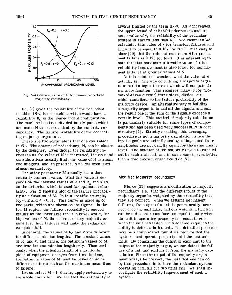
In many cases, electronic equipment is built sothat repair can be effected quickly. For instance,tubes in equipment can be removed and replaced in FNa very simple manner. Several methods of redun-dancy have been built into equipment which automatethe replacement of failed components. These meth- Fig. 9-Active switching redundancy.ods require a detector that decides that the equip- Since failure detecting and switching are usuallyment has failed and further indicates which quite difficult to perform, large subassemblies arecomponent needs replacing. A mechanical device replaced at a time. Typically, the complete systemis required which replaces the indicated component. is switched in or out by itself, or it may be dividedThese detectors and mechanical repair men are . .
ainto *USt a few subassemblies which are switched.very complicated devices and usually much simpler F
substitutesareused. ~~~Fig. 9 shows a diagram of active redundancy.All' the units are performing the same function.
The most common method of implementing tinsredundancy is to replace components by switching Initially, function unit 1 is used until it fails, thenredundancyomis nto treplace dcomponents lby switching the output is taken from unit 2 if it is functioningin a new component instead of physically removing prelyWhnui2fas,teoptswchsthe old unit and installing a new one. Also, the fail- ainseppe. The i procedure isrpet untciure detector is so complicated that this portion of again stepped. This procedure iS repeated untl
na failure there are no units that are operating. The proba-the systrremdis,leftfothe operator.will Onc bility that at least one of the units is still workinghas occurred, the operator will manually initiate lactions which will eventually switch in the new unit. is
There are two types of switching redundancy-standby redundancy and active redundancy. When [ -(l-r)n|,standby redundancy is used, the redundant unit isnotaenergizedubeforenitisuswi,theredunanto us. ti where r is the reliability of one unit and there arenot energized before it is switched into use. That nsuhnisailbeIftewtchsafiurn such units available. If the switch has a failureis, the power is turned on at the time when the unit .. .is put into use. The active redundancy, on the other poaiityshand, keeps the reserve unit in operating conditionso that only the input or output circuits need be R = (l-s) [ l -(l r)n] (23)switched. Standby redundancy provides better pro-tection against failures because the reserve unit is This equation gives the reliability of one redundantnot in use until the prime unit fails. However, it unit. If we desire to apply the redundancy at ahas the disadvantages of requiring a more compli- hv
y ycated switch and requiring a period of time for epsiinitializing the equipment conditions. Active redun-dancy requires a smaller amount of time for the R = 1i(-s) 1-t 1-Ro M L (24)switching operation. Thus, every time a failure R ( L ( o )ni(Joccurs, the equipment will be down for a shortperiod of time when switching type of redundancy where the nonredundant system has a reliability Ronis used. and the redundancy has been applied to M statisti-
Because most of the decision is typically done cally independent subunits of equal reliability. RRmanually by the operator, the switching type re- is the reliability of the redundant system.dundancy can be used in conjunction with analog More accurate analysis has been performed,equipment. The devices are not limited to select which considers all the individual failure prob-one of a discrete set of conditions. abilities of the switch and failure detector [10] .

54 IEEE TRANSACTIONS ON RELIABILITY June
The results show that there exists an optimum at a rapid rate. When errors do occur, the com-component level where this type of redundancy puter will slow down and repeat the computationsshould be applied. The optimum level depends until the correct solution is obtained. Here weupon the reliability of the switching and detecting have an example of time redundancy in computingequipment. equipment.
Another possibility of building time redundancyinto computations is to perform the same compu-
Time Redundancy tation several times and then select one resultbased on several calculations. For instance, each
All methods of redundancy that correct perma- bit of a calculation could be computed three timesnent failures also correct transient failures. and the correct result could be assumed to be theTransient failures are occasional equipment fail- result that at least two computations produced.ures which become repaired after a very short This scheme would be the time domain equivalenttime period. For instance, a computer may "drop" to the equipment domain majority redundancy. Thea bit. Since it is assumed that the computer will other equipment redundancies could be implementedbe operating properly a short time after the failure, in the time domain in a similar fashion.the same computation may be made correctly short- When coding theory was in its infancy, codingly after the transient failure occurs. This suggests methods such as the one discussed above were in-all forms of time redundancy for coping with tran- vestigated. By present day standards in codingsient failures. theory, transmitting one bit three times and select-
Coding theory of communications theory is ing for the result the value which was received atclosely related to time redundancy. In communi- least twice in the three tries is considered ineffi-cation systems, however, no computation is per- cient. Three times time redundancy is used in thisformed. The important operation is to get method. One could compute a word of bits at oneinformation from one place to another without time and associate some check bits with a word inerrors. such a manner that the check bits could be used to
Statistical coding theory has been studied ex- correct any errors in the computation. In thistensively since Shannon first introduced it in 1948. manner, large reduction in errors can be obtainedMost work in this field is based on the two original by use of less redundancy.papers of Shannon, "A Mathematical Theory of If fancy codes are used to increase the errorCommunication" [26] and "Communication in the correcting efficiency, the coders and decodersPresence of Noise" [27]. This theory asserts that become very complicated and become unreliableif a block of binary digits is coded into another themselves. So, for complicated codes, this typeblock of binary digits (usually longer than the of redundancy must be applied to large subsystemsoriginal block), binary information can be trans- in order to minimize the degradation of the equip-mitted with any desired accuracy as long as the ment by the coder and decoder unreliability [1].amount of information is less than a particular The alternative is to use an inefficient codingparameter of the communication channel. This scheme at the small subsystem level with theshows that we have gained error protection by quite simple coder-decoder combination.using more time than is necessary to transmitthe original information. This could be termed APPLICATION OF REDUNDANCIES"time redundancy."
Time redundancy has received little interest asa device which corrects temporary component fail- It is difficult to answer the question of when re-ures. Usually these failures are rare and unimpor- dundancy should be used. The additional cost of thetant as compared to noise introduced by other redundant equipment in the form of additional com-random sources; However, sometimes one is in- ponents must be justified by the reliability improve-terested in protecting against an isolated malfunc- ment that is obtained by redundancy application. Intion of the circuitry. many instances, the reliability of the equipment is
Kilmer has proposed a computer design which sufficiently important so that equipment redundancyuses redundant circuitry to detect failures [13]. is not ruled out just because of cost.Then, if failures occur, the computer will repeat Redundant equipment has frequently been used inthe computation until it computes the correct re- satellite-borne equipment. While the weight andsult. This machine trades off equipment for a size of the additional components is very undesir-delay in computations. The machine is built so able, the cost of launching a satellite is so greatthat when no errors occur, the computer performs that, by prolonging the life of the satellite by a very

1964 TEOSTE: DIGITAL CIRCUIT REDUNDANCY 55
short time, a large economic over-all gain is ob- 1.o NOWtained. Also, sometimes the payload equipment is F REDUNDANTso unreliable that a nonredundant payload may fail m 0.8
before the satellite ever gets into orbit. o MAJORITY / //DGATE0 0.6 REDUNDAN~TCONCRREUDTReal time systems require extremely high relia- (N=5) MODIFIED MAJORITY
bility. In some cases, if a failure occurs, the im- w REDUNDANT (N=5)Cr0.4~ MORE-SHANNON
pact of the incorrect calculations is tremendous. D/ REDUNDANT PARALLELFor instance, if one has a computer perform the L 02 REDUNDANTswitching operations in a railroad yard where the Lcomputer failure can cause an accident in which 2 6 6 10much property and possibly lives are lost, one x0t - NORMALIZED TIMEwould not hesitate to spend much effort in providing ,
for the computer reliability. Fig. 10-Comparison of redundancy methods.Before applying redundancy, the nature of the F
failures has to be known. Redundancy is useful sually the redundant equipment is more reliableonly for particular type of failures. An important initially, but after some use the equipment relia-point which is often overlooked is that failures 9 bility decreases rapidly. Fig. 10 shows the failurewhich redundancy is capable of correcting must
p
be tatstiall inepeden. Te odinry and~> probability as a function of time. A curve is shownbe satisicaly inepedent Theordiary and for the nonredundant equipment which is the usualfailures of equipment fall into this category; how- X utwever, these failures are only one part of the total exponential curve, Ro = e o The time is normal-failures. The requirement for statistical independ- ized so that the Xot which corresponds to the meanence was brought out by a recent Telstar experi- time to failure of the nonredundant equipment isment [1 ]. The silicon transistors in the Telstar equal to one. The redundant equipment reliabilityredundant command decoders failed due to high- is calculated by use of (7), (11), (15), (16), and (22).energy radiation. Since the two decoders received The curves are calculated for a 500 active elementthe same radiation, the redundancy was useless. circuit.However, if the two units were located in different The majority redundancy and the modified ma-parts of the satellite and provided with different jority redundancy, described by (7) and (11), as-types of shielding, the redundancy might have sume that a majority gate reliability is equivalenthelped the situation.
to athree active element circuit [i.e., (1-E), = R J,and M was chosen so that the reliability was maxi-
Reliability Comparison of Redundancy Techniques mized at the point where Fo = 0.9. Optimum M cannotbe used for all values of Xot, since the circuit re-
The equations for reliability estimates have beet quires a change for each value of M. Since majorityderived for several redundancy techniques in the and modified majority redundancy would yield thepreceding sections. It would be interesting to same curve for three times redundancy, five timesevaluate these equations for particular equipment duplication was used for illustrating purposes.characteristics to see how the reliability of the dif- The Moore-Shannon redundancy was calculatedferent redundancy methods compare with each other. directly by (15) with K = 500. Similarly, the par-
It would be difficult to compare the more con- allel redundancy was calculated by (16) with K = 500ventional circuit redundancies to multiplexed, and n = 2.switching, or time redundancy. These types of re- The gate connector redundancy was obtained bydundancy are applied to either large subsystems of (22) with K = 500, which already assumes a gate tothe main system, or they are dependent on the op- be equivalent to a one active element circuit and theeration of the over-all system which makes it quite function boxes equivalent to two active elementdifficult to compute the reliability improvement in circuits.a general fashion. Because of this difficulty, the Fig. 10 clearly shows that the parallel redun-reliability comparison does not include these re- dancy, a special case of Moore-Shannon redundancy,dundancy techniques. provides the best reliability improvement for only
When equipment is being used continually and two times redundancy. This is a fine conclusion,replaced when it fails, a suitable criterion for but we must note that this type of redundancy onlyestimating the equipment usefulness is the mean provides for one type of failure correction, namely,time to failure. It is important to know how the open type failures. If a completely redundant pieceprobability of failure varies as time progresses. of electronic gear were to be built, one would like
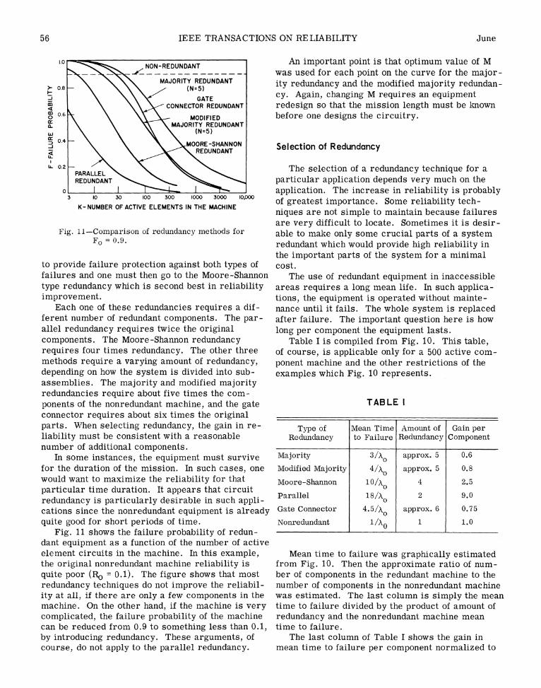
56 IEEE TRANSACTIONS ON RELIABILITY June
1.0 NON-REDUNDANT An important point is that optimum value of M+-- -@iK ~ . - was used for each point on the curve for the major-
> 0.8 \ \\\MAJORITY REDUNDANT ity redundancy and the modified majority redundan->_ 0.8 ~~~~~~~(N=5)
\ \\\</GATE Cy. Again, changing M requires an equipmentco \ \\,>CONNECTOR REDUNDANT redesign so that the mission length must be knowno 06 MODIFIED before one designs the circuitry.a. \ \ MAJORITY REDUNDANT
w ~~~~~~~~~~(N=5)It:0.4 MOE-SH NORE-HAN Selection of Redundancy
U. 0.2 PARALLEL The selection of a redundancy technique for a
REDUNDANT particular application depends very much on thec application. The increase in reliability is probably3 10 30 100 300 000 3000 I0,00 of greatest importance. Some reliability tech-
K-NUMBER OF ACTIVE ELEMENTS IN THE MACHINEniques are not simple to maintain because failuresare very difficult to locate. Sometimes it is desir-
Fig. 11-Comparison of redundancy methods for able to make only some crucial parts of a systemFo = 0.9. redundant which would provide high reliability in
the important parts of the system for a minimalto provide failure protection against both types of cost.failures and one must then go to the Moore-Shannon The use of redundant equipment in inaccessibletype redundancy which is second best in reliability areas requires a long mean life. In such applica-improvement. tions, the equipment is operated without mainte-
Each one of these redundancies requires a dif- nance until it fails. The whole system is replacedferent number of redundant components. The par- after failure. The important question here is howallel redundancy requires twice the original long per component the equipment lasts.components. The Moore-Shannon redundancy Table I is compiled from Fig. 10. This table,requires four times redundancy. The other three of course, is applicable only for a 500 active com-methods require a varying amount of redundancy, ponent machine and the other restrictions of thedepending on how the system is divided into sub- examples which Fig. 10 represents.assemblies. The majority and modified majorityredundancies require about five times the com-ponents of the nonredundant machine, and the gate TABLE Iconnector requires about six times the originalparts. When selecting redundancy, the gain in re- Type of Mean Time Amount of Gain perliability must be consistent with a reasonable Redundancy to Failure Redundancy Componentnumber of additional components. _
In some instances, the equipment must survive Majority 3/X approx. 5 0.6for the duration of the mission. In such cases, one Modified Majority 4/Xo approx. 5 0.8would want to maximize the reliability for that Moore-Shannon 10/Ao 4 2.5particular time duration. It appears that circuit Pa11l1 1 8/X 2 9.0redundancy is particularly desirable in such appli- Palel 145 2 9.0cations since the nonredundant equipment is already Gate Connector approx. 6 0.75quite good for short periods of time. Nonredundant 1/0 1 1.0
Fig. 11 shows the failure probability of redun-dant equipment as a function of the number of activeelement circuits in the machine. In this example, Mean time to failure was graphically estimatedthe original nonredundant machine reliability is from Fig. 10. Then the approximate ratio of num-quite poor (IR, = 0.1). The figure shows that most ber of components in the redundant machine to theredundancy techniques do not improve the reliabil- number of components in the nonredundant machineity at all, if there are only a few components in the was estimated. The last column is simply the meanmachine. On the other hand, if the machine is very time to failure divided by the product of amount ofcomplicated, the failure probability of the machine redundancy and the nonredundant machine meancan be reduced from 0.9 to something less than 0.1, time to failure.by introducing redundancy. These arguments, of The last column of Table I shows the gain incourse, do not apply to the parallel redundancy. mean time to failure per component normalized to
1964 TEOSTE: DIGITAL CIRCUIT REDUNDANCY 57
the nonredundant machine. The numbers show that bilities are 0.99, it would be absurd to worry aboutif systems can be replaced with ease, the nonredun- the reliability of the already reliable components.dant machine provides a longer mean time to failure Redundancy applied to the unreliable subsystemfor the same cost unless Moore-Shannon or parallel would certainly buy much more in over-all reliabil-redundancy were to be used. For instance, five ity than would the application of redundancy to onenonredundant machines, which would have as many of the already reliable units. By the same argument,components as one majority redundant machine, it may be desirable to add different amounts of re-would have a 5/X0 mean time to failure; but one dundancy to different portions of a system. Thesemajority redundant machine has a 3/SO mean time ideas can be carried down to the component levelto failure. Thus, it would be more economical to where perhaps resistors and capacitors are notkeep replacing nonredundant machines than to use made redundant, while redundancy is applied to theone majority redundant machine. This conclusion less reliable components.is true only if replacement is "easy" and there are A second method of selecting which subsystems500 active element components in the machine. As should be made redundant depends on the conse-the number of active elements in the machine in- quences of a failure of the subsystem. If the failurecreases, the reliability improvement of redundant of a subsystem is relatively unimportant, the over-equipment becomes more favorable. Of course, if all cost can be reduced by leaving that subsystemreplacement of equipment is not "easy," the redun- nonredundant. However, if the failure of the sub-dancy techniques would be more desirable. system causes some catastrophic situation, the ,'11L
We also note that Table I shows a great improve- subsystem should be made redundant. 4ment for Moore-Shannon and parallel redundancy.The parallel redundancy cannot be applied in Sample Applicationgeneral to all types of circuitry and components.However, if only one type of failure is expected for Several redundancy techniques have been useda particular component, its use would be much in isolated cases in electronic equipment. Simplemore efficient. parallel redundancy has been used for a long time
On the basis of the above discussion about mean in some switching applications, particularly inlife, it appears that Moore-Shannon redundancy pro- firing and detonating controls. Since componentsvides most failure free operation against shorts and can be connected in this fashion only in specialopens for the least amount of redundancy. cases, usually a few components in a system can
The failure detection in some redundancy meth- be made redundant this way. The majority redun-ods is very difficult. In Moore-Shannon redundancy, dancy is applicable to a wider variety of compo-a component can fail, but the circuit still performs nents or subsystems, consequently majorityas expected. The multiple line redundancies are redundancy has been applied more throughout theprobably the easiest to trouble shoot. The lines equipment. However, the optimum component or-which should carry identical information can be ganization level has usually not been achieved.compared against each other. If a failure has oc- The redundancy has been applied to large sub-curred, one or more of the lines will be different systems and only to the more critical units.from the others and the failed unit is located Probably the most common form of redundancypromptly. Calculations show that extremely long is the switching redundancy. In radar sets, forlife can be obtained from redundant equipment if instance, several receivers are kept on hand somaintenance is performed quickly after a failure that a new receiver could be substituted while theoccurs. The mean time to failure of a large scale original one is being repaired. Such a situationdigital computer could be increased from maybe lies on the borderline of redundancy and mainte-100 hours to 40 years by use of three times redun- nance technique. In other applications such asdancy such as shown in Fig. 7. On the basis of bombing systems, the additional redundant gearconvenient maintenance techniques, the multiline is used without the original one being repaired.redundancy methods are preferable. The repair is delayed until the end of the bombing
In the previous discussions, redundancy was ap- mission. More recent applications have appearedplied to every component in the machine. The in satellite equipment where units are trulyover-all system reliability must be observed and switched. Since no repair is involved in satelliteonly the less reliable components should be made application, the spare equipment indeed acts asredundant in order to keep the redundancy to a redundant equipment.minimum. As an example, if we have a system From our comparisons of redundancies, wewhich consists of ten units of equal size but one concluded that Moore-Shannon redundancy pro-has a reliability of 0.1 while the other nine relia- vided the most reliability improvement and could
58 IEEE TRANSACTIONS ON RELIABILITY June
FLIP -FLOP + lOv
ALL TRANSISTORS ZN385ALL DIODES CTP521ALL RESISTANCES IN kohmsALL CAPACITORS IN mmfi
I+lOv ____ _ _ _ _ _ _ _ _ _ _ _ _ _
200V
JLI4 430 430 30 30
3 430 430 30INPUT| 3I l
<5 5 5 S SS% 5+
N~~~~~~~ ~4A4X OUTPUT
Fig. 12-Moore-Shannon redundant flip-flop.
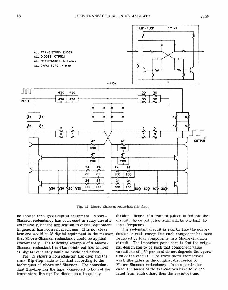
be applied throughout digital equipment. Moore- divider. Hence, if a train of pulses is fed into theShannon redundancy has been used in relay circuits circuit, the output pulse train will be one half theextensively, but the application to digital equipment input frequency.in general has not seen much use. It is not clear The redundant circuit is exactly like the nonre-how one would build digital equipment in the manner dundant circuit except that each component has beenthat Moore-Shannon redundancy could be applied replaced by four components in a Moore-Shannonconveniently. The following example of a Moore- circuit. The important point here is that the origi-Shannon redundant flip-flop points out how almost nal design has to be such that component valueall digital circuitry could be made redundant. variations of ±50 per cent do not degrade the opera-
Fig. 12 shows a nonredundant flip-flop and the tion of the circuit. The transistors themselvessame flip-flop made redundant according to.the work like gates in the original discussion oftechniques of Moore and Shannon. The nonredun- Moore-Shannon redundancy. In this particulardant flip-flop has the input connected to both of the case, the bases of the transistors have to be iso-transistors through the diodes as a frequency lated from each other, thus the resistors and

1964 TEOSTE: DIGITAL CIRCUIT REDUNDANCY 59
-J8
0.6 - / ALL REDUNDANT COMPONENTS
_ REDUNDANT DIODES AND TRANSISTORS ONLY,] 0.4
o 4 8 12 16
TIME (years)
Fig. 13-Reliability of flip-flop.
capacitors in the base circuit act as if they were individual component (except the transistor cir-part of the transistor. cuits), which provides better failure protection.
The reliability of the redundant flip-flop was One would then expect that the reliability improve-calculated by substituting the redundant component ment would be still better than what was estimatedreliability for each component in the nonredundant previously. Since the transistors contribute mostcircuit. The reliability calculations were made by of the unreliability, the additional improvement isassuming the following failure rates for the dif- not great.ferent components which are typical of present It is not clear that all digital circuits can easilyday good military-type components: be made redundant by Moore-Shannon redundancy.
Circuits which contain critical components may notdiodes (germanium) 0.219x 10⁻⁶ failures/hour be amenable to the Moore-Shannon technique. Thetransistors (germanium) 0.654 x 10⁻⁶ failures/hour gate connector redundancy was originally devisedresistors (composition) 0.054 x 10⁻⁶ failures/hour to be used with the Moore-Shannon redundancy incapacitors (mica) 0.009 x 10⁻⁶ failures/hour places where Moore-Shannon techniques proved
difficult to apply. The combination of the two re-The results are plotted in Fig. 13 in comparison dundancies should provide design techniques forwith the nonredundant circuit. all digital circuitry.
Looking at the failure rates given above, we see The application of redundancy increased thethat the failure rates of transistors and diodes are number of components in the flip-flop from 16 toone or two orders of magnitude greater than the 68 which is an increase of 4.25. If only transistorsfailure rates of resistors and capacitors. One then and diodes would be made redundant, the increasewonders if a considerable saving in components would be 2.625. Leaving some components nonre-could be gained at the expense of very little degra- dundant brings the component increase to a verydation of reliability by not making the resistors and nominal value, while the reliability improvementcapacitors redundant. Fig. 13 shows the reliability stays almost the same.of the flip-flop if resistors and capacitors are left It turns out that the required power to operatenonredundant. The difference in reliability is seen the redundant flip-flop is not much higher than the 1to be minute. However, the number of components nonredundant unit. The current through the tran-has been reduced from 68 to 42, which is almost sistors should be approximately the same since the40 per cent reduction in the number of components. current is determined mainly by the load resistor.
When the Moore-Shannon redundancy reliability However, if power consumption is of prime impor-was derived, the switch-like circuit was assumed tance, one could not decrease the current down toto be one active element with its associated com- as low a level as one might be able to do with aponents. Here we have applied redundancy to each nonredundant circuit.

60 IEEE TRANSACTIONS ON RELIABILITY June
REFERENCES [10] B. J. Flehinger, "Reliability improvementthrough redundancy at various system
Much of the literature on redundancy has been levels," IBM J. Res. & Dev., vol. 2, pp. 148-scattered in numerous scientific publications. 158; April, 1958.Here we have selected a set of these articleswhich are closely related and describe the re- [11] M. Getler, "Telstar repair may have widedundancy methods in a more coherent manner. import," Missiles and Rockets, vol. 12,
p. 17; January, 1963.[1] D. B. Armstrong, "A general method of
applying error correction to synchronous [12] R. Gordon, "Optimum component redundancydigital systems," Bell Sys. Tech. J., vol. 40, for maximum system reliability," Opera-pp. 577-593; March, 1961. tions Research, vol. 5, pp. 229-243; April,
1957.[2] R. E. Barlow and L. C. Hunter, "Criteria
for determining optimum redundancy," IRE [13] W. L. Kilmer, 'An idealized over-all error-TRANS. ON RELIABILITY AND QUALITY correcting digital computer having only anCONTROL, vol. RQC-9, pp. 73-77; April, error-detecting combinational part," IRE1960. TRANS. ON ELECTRONIC COMPUTERS,
vol. EC-8, pp. 321-325; September, 1959.3] W. G. Brown, J. Tierney, and R. Wasser-
man, "Improvement of electronic computer [ 14] M. Kohen, "Extension of Moore-Shannonreliability through the use of redundancy," model for relay circuits," IBM J. Res. &IRE TRANS. ON ELECTRONIC COM- Dev., vol. 3, pp. 169-186; April, 1959.PUTERS, vol. EC-10, pp. 407-416;September, 1961. [ 15] L. L6fgren, "Automata of high complexity
and methods of increasing their reliability[4] G. Buzzell, W. Nutting, and R. Wasserman, by redundancy," Inform. Control, vol. 1,
"Majority gate logic improves digital sys- pp. 127-147; May, 1958.tem reliability," 1961 IRE INTERNATIONALCONVENTION RECORD, Pt. 2, pp. 264-270. [16] 0. Lowenschuss, "Restoring organs in re-
dundant automata," Inform. Control, vol. 2,[5] J. H. S. Chin, "Circuit redundancy," 1959 pp. 113-136; June, 1959
IRE NATIONAL CONVENTION RECORD,Pt. 6, pp. 44-50. [17] W. C. Mann, "Systematically introduced re-
dundancy in logical systems," 1961 IRE[6] C. J. Creveling, "Increasing the reliability INTERNATIONAL CONVENTION RECORD,
of electronic equipment by the use of re- Pt. 2, pp. 241-263; March, 1961.dundant circuits," PROC. IRE, vol. 44,pp. 509-515; April, 1956. [18] E. F. Moore and C. E. Shannon, "Reliable
circuits using less reliable relays, J.[7] L. Depian and N. T. Grisamore, "Reliability Franklin Inst., vol. 262, pp. 191-208,
using redundancy concepts," IRE TRANS. September, 1956; pp. 281-297, October,ON RELIABILITY AND QUALITY CONTROL, 1956.vol. RQC-9, pp. 53-60; April, 1960.
[19] D. F. Morrison and H. A. David, "The life[8] W. E. Dickinson and R. M. Walker, "Relia- distribution and reliability of a system with
bility improvement by the use of multiple- spare components," The Annals of Mathe-element switching circuits," IBM J. Res. matical Statistics, vol. 31, pp. 1084-1094;& Dev., vol. 2, pp. 142-147; April, 1958. December, 1960.
[9] P. Elias, "Computation in the presence of [20] F. Moskowitz, "The statistical analysis ofnoise," IBM J. Res. & Dev., vol. 2, pp. 346- redundant systems," 1960 IRE INTER-353; October, 1958 NATIONAL CONVENTION RECORD, Pt. 6,
nnc 78-89-
1964 TEOSTE: DIGITAL CIRCUIT REDUNDANCY 61
[ 21] __ "The analysis of redundancy networks," [28] R. Teoste, 'Design of a repairable redundantTrans. AIEE, vol. 77 (Commun. and computer," IRE TRANS. ON ELECTRONICElectronics, Pt. 1), pp. 627-632; November, COMPUTERS, vol. EC-11, pp. 643-649;1958. October, 1962.
[ 22] D. A. Paynter and V. P. Mathis, "Redundancy [29] "Reliability of Redundant Computers,"techniques in reliable power supply design," Lincoln Lab., M.I.T., Lexington, Mass.,Proc. 1961 Internat'l Solid State Circuit Rept. No. 21G-0029, ASTIA Doc. No. 260494;Conf., pp. 50-51. March, 1961.
[23] W. H. Pierce, "A Proposed System of Re- [30] 'Some Reliable Redundant Circuits," -dundancy to Improve the Reliability of Lincoln Lab., M.I.T., Lexington, Mass., °46Digital Computers," Applied Electronics Rept. No. 21G-8001, ASTIA Doc. No. 284793;Lab., Stanford University, Stanford, Calif., June, 1961.Rept. No. TR 1552-1; July, 1960. [31] J. G. Tryon, "Quadded logic," in "Re-
[ 24] D. E. Rosenheim and R. B. Ash, "Increasing dundancy Techniques for Computing Sys-reliability by use of redundant machines," tems," Spartan Books, Washington, D. C.,IRE TRANS. ON ELECTRONIC COM- pp. 205-228; 1962.PUTERS, vol. EC-8, pp. 125-130; June, 1959. 32] J. Von Neumann, "Probabilistic logics and
[ 25] S. Schneider and D. H. Wagner, "Error de- the synthesis of reliable organisms from[25]~~~~~~~~~~~~S= unreliable components," in "Annals oftection in redundant systems," Proc. 1957Western Joint Computer Conf., pp. 115-121. Mathematics Studies," Princeton University
Press, Princeton, N. J., no. 34, pp. 43-98;[ 26] C. E. Shannon, "A mathematical theory of 1956.
communication," Bell Sys. Tech. J., vol. 27, 33] R. H. Wilcox and W. C. Mann, "Redundancypp. 379-423, July, 1948; pp. 623-656, Techniques for Computing Systems,"October, 1948. Spartan Books, Washington, D. C., 1962.
[27] "Communication in the presence of (This book contains the Proceedings of thenoise," PROC. IRE, vol. 37, pp. 10-21; Symposium on Redundancy techniques forJanuary, 1949. Computing Systems, as well as a relatively
complete bibliography on redundancytechniques.)