Embed Size (px)
Citation preview

Document Number DDC ALP 7002 01 AD
ALP48
Digital Command
Microphone
Current
Thinking
Programming Manual February 2009
Software Version 3.8

ALP48 Programming Manual Page 2 of 2 ©2009 Current Thinking Ltd
Introduction
Voice Alarm (VA) systems are the quickest way to evacuate the public & staff
from a building.
Following fire detection, automated messages control the flow of people in
stairwells and corridors allowing an orderly evacuation without panic. These
messages are supplemented by spoken messages from the fire service or
management suite confirming the validity and need to leave the building.
This positive confirmation speeds evacuation and avoids the "false alarm"
mentality reducing the risk of death from fire.
Suitability
Voice Alarm systems are recommended for all public buildings and multi story
buildings over four floors by BS5588.
In public buildings it's not possible to fire drill the public, as they visit the
premises infrequently, so systems such as Voice alarms save valuable time in
evacuating the building.
The use of phased messages in multi-story buildings prevents over-crowding in
stairwells and at exits, preventing secondary injuries. In phased evacuation, the
floor in fire receives the evacuate message, and the floor above & below receive
an alert message, preparing them for evacuation.
In more complex scenarios the use of multiple alert and evacuate messages can
be beneficial, messages telling the evacuees they are going the right way, and
messages asking people to make way for people leaving evacuated areas. These
additional messages can dramatically speed up the evacuation especially in malls
and large airport environments.
Overview
For small and medium sized installations this self-contained voice alarm controller
provides an ideal solution.
The basic controller has 4 monitored outputs, and the following inputs: 2 all call
fire microphone ports, a data control port for networking & configuration, 2 four
zone high priority microphone ports, 2 digital message slots (allowing four
messages to be held in hardware), a six input fire alarm interface with common
de-latch input (24V voltage inputs for connection to sounder circuits), 2 low
priority zoned microphone ports, and three stereo music inputs.
The front panel LCD allow selection of volumes, music sources and configuration
of all functions, as well as providing access to the 99 event log. In the event of
processor failure the 2 fireman’s inputs can access the whole system in line with
EN60849 and BS5839 pt 8.
Standards Compliance
The @udio Logistics ALP48 complies with all the relevant current Voice Alarm
standards including BS5839 parts 1,4 & 8 and EN60849.
We are also monitoring the meetings of the EN54-16 committee to ensure we will
comply when this is released.
Additionally the ALP48 complies with the EMC requirements of EN55103-1 and
EN55103-2.

ALP48 Programming Manual Page 3 of 3 ©2009 Current Thinking Ltd
Navigating the ALP48 Menus
All functions of the ALP48 can be configured using the front panel LCD and the
three navigation Keys (LEFT, RIGHT, and ACCEPT), abbreviated to <L) for LEFT,
[A] for ACCEPT and (R> for RIGHT.
When the ALP48 is powered up, it will always revert to the Root Menu.
General Menu Format
When [A] is pressed for the first time from the root screen, the display will show
as follows
ALP v3.8-User
Back
>View audio sources
View fault status
The top line shows the panel type with version number and the menu level. The
next 3 lines show various menu options: the current option, the preceding option
and the following option.
The first menu option will become the current menu option if <L) is pressed.
The second menu option will always be prefixed by a right chevron ‘>’. This
indicates the current menu option. Pressing [A] will take you to this option.
The last menu option will become the current menu option if (R> is pressed.
When in a configuration menu, a variety of options may be displayed. Each
option will either have a colon ‘:’, or a chevron ‘>’ followed by the value for that
option, e.g. Net address>1
The chevron will indicate which option is currently selected. Use the <L) and (R>
buttons to toggle through the various values for that option. When the correct
value is chosen, press [A] to move to the Next option.
Each configuration screen will have an option in the bottom right. By default, this
option will be Next. The different values for this option are:
Next: moves cursor back to first option on this page, or to first option on
next page if there is more than one page
Save: saves the new configuration, and moves back to the menu list.
Quit: discards any changes made, and moves back to the menu list.
Inputting Text
All text input on the ALP48 uses the same technique. The text to be edited either
begins with a right chevron ‘>’, or is bracketed by chevrons ‘>’ and ‘<’. The
number of characters allowed depends upon the text being edited.
For example,
Edit fault text
Fire microphone 1

ALP48 Programming Manual Page 4 of 4 ©2009 Current Thinking Ltd
>Fault on fire mic 1
:Next
When text entry is used, the current text for the entry is displayed, with the first
character highlighted using an underscore, this is the character which is altered
using <L) and (R> keys and follows the characters in this List:
ABCDEFGHIJKLMNOPQRSTUVWXYZ 0123456789~
abcdefghijklmnopqrstuvwxyz@?<>&#()+-=ÿ
Special characters appear at the end of each line in the list, '~' and 'ÿ', these are
the insert and end of text markers respectively.
Press [A] to accept the current character and moves to the next character.
Edit fault text
Fire microphone 1 >Fault on fire mic 1
:Next
When the last character is entered, or [A] is pressed on the end of text 'ÿ'
character, the Next option banner is selected.
If the 'ÿ' (end of text) character is used to terminate text entry, the character
position containing this character is filled with a space, and all characters to the
right of the end of text character are replaced with spaces.
Pressing [A] on the '~' (insert) character will shift the text from the current
location onwards to the right by 1 space, and put a SPACE character at the
current location.
If [A] is pressed on the Next option, the cursor goes back to editing text position
1.
If <L) or (R> is pressed on next, the options will scroll through Next, Save, and
Quit.

ALP48 Programming Manual Page 5 of 5 ©2009 Current Thinking Ltd
Root Menu
The root display shows the version number of the firmware on the panel (ALP
v3.8), the Site name (which defaults to @udio Logistics), and a banner
indicating the general status of the system. The date & time shown are the
current date & time, pressing tick takes you to the User Access Menu.
Root Menu (No Faults)
When the system has no faults, the banner shows System Healthy.
ALP v3.8
@udio Logistics
- System Healthy -
08:35:00 18|02|09
Root Menu (Faults)
When the system is in fault, the health banner shows System in Fault.
ALP v3.8
@udio Logistics
- System in Fault -
08:35:00 18|02|09
Press [A] to enter the user level menu. The user level menu will allow you to
view the fault status and the audio output status of the network. You can also log
in as either a manager or an engineer to gain access to the configuration
functions.

ALP48 Programming Manual Page 6 of 6 ©2009 Current Thinking Ltd
User Level Menu
For the user menu, the following menu items are available. (Some items may not
be shown depending on system configuration and status. These will be described
in the appropriate section.)
Accept faults
If the buzzer is sounding, pressing [A] will accept the fault and silence the buzzer.
When the buzzer is silenced, it will emit a single beep once every 15 seconds to
indicate the system is still in fault.
This menu option is only shown when the buzzer is sounding in a cadence, and
Mute Buzzer is enabled in the Setup menu described later.
View audio sources
This is a diagnostic display showing the current audio routing of all configured
DCA4s on the network. Each page shows up to 4 DCAs.
Press (R> to scroll forward through the pages;
Press <L) to scroll backward through the pages;
Press [A] to exit this menu.
Each line will show the address number for that DCA4 along with the audio input
for all 4 outputs. Each audio input has a 3 letter designation. If this DCA4 is not
detected on the network, then Not detected will be shown on this line.
1: BGM BGM BGM BGM
2: - - - - 3: Not detected
4: Evc Alt Alt Alt
Audio input designation
Each audio input has a specific 3 letter designation. The only configurable
designations are for the 6 messages (see later).
' - ' No audio input
'FM ' Fire microphone
'Dat' Data microphone
'Hi ' High priority microphone
‘Tst’ Default for Message 1 on Store 1, configurable
‘Sec’ Default for Message 2 on Store 1, configurable
‘Evc’ Default for Message 3 on Store 1, configurable
‘Clr’ Default for Message 1 on Store 2, configurable
‘Stf’ Default for Message 2 on Store 2, configurable
ALP v3.8-User
Back
>View audio sources
View fault status Accept faults
Log in

ALP48 Programming Manual Page 7 of 7 ©2009 Current Thinking Ltd
‘Alt’ Default for Message 3 on Store 2, configurable
'Lo '; Low priority microphone
'BGM' Background music
View fault status
This menu will show all the faults in the event log. It will filter out all other
events, showing faults only.
The display will show the following information:
The top line shows the event number and the total number of events. If this fault
occurred on a remote unit, it will display the address of this unit.
The second line shows the fault status, i.e. fault occurred or fault cleared.
The third line shows the type of fault.
The fourth line shows the time and date the fault occurred.
Press (R> to scroll forward through the faults, if there is more than one;
Press <L) to scroll backward through the faults, if there is more than one;
Press [A] to exit this menu.
This menu option is only shown if the Faults option is enabled in the Setup
menu described later.
Login
This allows you to enter a PIN number to gain access to either Management (level
3) or engineer (level 4) menu items, the PIN for each level is different, and can
be changed with the correct access level.
<L) & (R> alter the selected value, [A] moves to the next digit.
An incorrect PIN will show an error message. Pressing any key will return you to
the User menu with Log in selected.
Back
This menu will return the user back to the previous menu level. In this case, it
will return the user back to the root menu.
Event 11/30-Node 2
Fault occurred Unit not detected
09:03:13 18|02|09
Enter PIN to log in
-0***-

ALP48 Programming Manual Page 8 of 8 ©2009 Current Thinking Ltd
Manager Level Menu
If the manager PIN has been entered the display below is shown, if the Engineer
PIN is entered, the Engineering menu is displayed, this is described later.
The manager functions are a subset of the engineer functions. It allows you to:
View the audio status and the fault/event log
Specify which options to show in the user menu
Determine behaviour of buzzer
Change the microphone volume
Set the time and date
Log off
This menu will take you back to the root menu. You will have to log back in to
regain access to any of the manager or engineer functions.
View audio sources
This menu shows the audio input sources for the network. It is described in detail
above.
View fault status
This menu shows the faults only in the event log. It is described in detail above,
except that this menu is always shown.
Accept faults
If the buzzer is sounding, pressing [A] will accept the fault and silence the buzzer.
When the buzzer is silenced, it will emit a single beep once every 15 seconds to
indicate the system is still in fault.
This option is only shown if the buzzer is sounding.
Setup
This menu allows you change the behaviour of the buzzer and controls which
menu options are available at the User level.
ALP v3.8-Manager
Change manager PIN
>Log off
View audio sources View fault status
Accept faults
Setup
View event log
Set volume
Set date & time
ALP48 Programming Manual Page 9 of 9 ©2009 Current Thinking Ltd
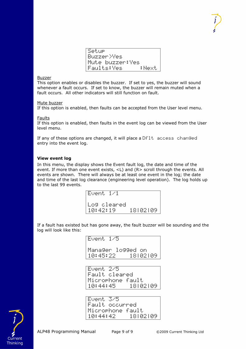
Buzzer
This option enables or disables the buzzer. If set to yes, the buzzer will sound
whenever a fault occurs. If set to know, the buzzer will remain muted when a
fault occurs. All other indicators will still function on fault.
Mute buzzer
If this option is enabled, then faults can be accepted from the User level menu.
Faults
If this option is enabled, then faults in the event log can be viewed from the User
level menu.
If any of these options are changed, it will place a Dflt access changed
entry into the event log.
View event log
In this menu, the display shows the Event fault log, the date and time of the
event. If more than one event exists, <L) and (R> scroll through the events. All
events are shown. There will always be at least one event in the log; the date
and time of the last log clearance (engineering level operation). The log holds up
to the last 99 events.
If a fault has existed but has gone away, the fault buzzer will be sounding and the
log will look like this:
Setup
Buzzer>Yes Mute buzzer:Yes
Faults:Yes :Next
Event 1/1
Log cleared
10:42:19 18|02|09
Event 1/5
Manager logged on
10:45:22 18|02|09
Event 2/5
Fault cleared
Microphone fault
10:44:45 18|02|09
Event 3/5
Fault occurred
Microphone fault
10:44:42 18|02|09

ALP48 Programming Manual Page 10 of 10 ©2009 Current Thinking Ltd
The sequence of events is:
At 10:44:42, a microphone fault occurred.
At 10:44:45, the microphone fault cleared
At 10:45:22, a user logged on with managerial privileges.
The following items are always noted in the event log:
Faults occurred
Faults cleared
Configuration changed
Manager or engineer logged in
Manager or engineer logged off
System initialised: this only occurs on unit power up
System reboot requested
Log cleared
As a result, an audit trail is shown on the status of the esystem, and any changes
made to the configuration.
Each menu option that adds an entry into the event log will be detailed in that
menu entry.
Set volume
This menu allows the user to change the volume settings for the microphone, and
sets the priority at which the microphone is to be used on the system.
Vol changes the microphone volume between 0db to -31db. The volume can
also be muted.
Bass changes the microphone bass level between +16db to -16db.
Mid changes the microphone mid level between +16db to -16db.
Treb changes the microphone treble level between +16db to -16db.
Lvl changes the priority of the microphone:
Page level will override all non-emergency pages and messages, but any
emergency page or message will still play.
Emer level will override all other audio except a dedicated fire microphone.
Note: if any key switch is defined as Emergency, this will override the Lvl
setting here. Configuring key switches is an engineer function, and will be
described later.
Any changes to the volume settings are always stored in the event log.
Set date & time
This menu allows the user to change the date and time, not only on the ALP, but
on every unit on the network, thus synchronising the time.
Set volume controls
Vol> 0 Bass: 0
Mid: 0 Treb: 0
Lvl:Page :Next

ALP48 Programming Manual Page 11 of 11 ©2009 Current Thinking Ltd
Use the <L) and (R> buttons to alter the currently selected element of the date
or time. Press [A] to move to the next element.
Saving the date and time places a Date + time changed entry into the log, and
updates the date/time on every unit on the network.
Change manager PIN
This menu allows the user to change the manager PIN.
The currently selected digit is shown as a digit, and not an asterisk. Use the <L)
and (R> buttons to scroll through the digits. Press [A] to move to the next digit.
Once you have entered the 4 digits for the PIN, the cursor will move to the first
digit of the Repeat PIN. Re-enter the same 4 digits.
Once the PIN has been entered twice, if Save is selected, it will check the 2 PINs.
If they are the same, the manager PIN will be updated and a Manager PIN
changed entry will be placed into the event log.
If they are different, a warning message will be displayed. Press any key to return
to the change manager PIN menu.
Set date and time
Date:>18|02|09
Time: 12:15:36
:Next
Set manager PIN
New PIN 0***
Repeat PIN ****
:Next

ALP48 Programming Manual Page 12 of 12 ©2009 Current Thinking Ltd
Engineer Level Menu
The engineering level menu allows access to all configuration and status displays.
It allows all items to be configured.
To enter the Engineering level, the user must log in using the valid Engineering
PIN.
ALP v3.8-Engineer
System reboot
>Log off
View audio sources View fault status
Accept faults
Setup
View event log
Set volume
Set date & time
Change manager PIN
Change engineer PIN
Button config
Set key switch
Message settings
Event log settings
Edit fault text
Monitor DCA4 fault
Edit site name
Network settings
Panel LED test
All menu options from Log off to Change manager PIN are detailed in the
Manager Level menu above.
Change engineer PIN
This menu allows the user to change the engineer PIN.
Set engineer PIN
New PIN 0***
Repeat PIN ****
:Next
The currently selected digit is shown as a digit, and not an asterisk. Use the <L)
and (R> buttons to scroll through the digits. Press [A] to move to the next digit.
Once you have entered the 4 digits for the PIN, the cursor will move to the first
digit of the Repeat PIN. Re-enter the same 4 digits.
Once the PIN has been entered twice, if Save is selected, it will check the 2 PINs.
If they are the same, the engineer PIN will be updated and a Engin’r PIN
changed entry will be placed into the event log.

ALP48 Programming Manual Page 13 of 13 ©2009 Current Thinking Ltd
If they are different, a warning message will be displayed. Press any key to return
to the change engineer PIN menu.
Button config
This menu allows the user to configure the panel buttons. As each button can
have one of multiple functions, it is necessary to first determine which function
the button is to have.
A submenu is displayed of the different button functions.
Button 1
Back
>Configure zone
Configure message
Special function
Button number
To configure a panel button, first that panel button MUST be pressed. The button
number will be displayed on the top line, and the button LED will show green,
indicating that that is the button to be configured.
Once the correct panel button has been selected, use the <L) and (R> navigation
buttons to scroll through this menu to select which function this panel button is to
perform.
Configure zone
This menu assigns this button to be a zone select button. All configured DCA4s
are shown in a list.
Button 1 Next
1| 1>Y 2:N 3:N 4:N
2| 1:N 2:N 3:N 4:N
3| 1:N 2:N 3:N 4:N
Each DCA4 is shown with 4 audio outputs. The network address of the DCA4 is
shown down the left side. The output number is shown across the line.
For example, 1| 1>Y 2:N 3:N 4:N means that this line refers to DCA4
address 1. The cursor is on output 1, and it is set to be included in this zone.
Outputs 2, 3 and 4 are not to be included in this zone.
To include a DCA4 output in the zone select list, press either <L) or (R> to toggle
the option for that output to Y. To deselect that output from the zone select list,
toggle the option to N. A DCA4 will only show in this menu if it has been
configured in the network setup (see later for details).
Press [A] to scroll through the outputs. The cursor scrolls from output 4 of the
current DCA4 to output 1 of the next DCA4. If on output 4 of the bottom DCA4,
the cursor scrolls to Next. Each page shows up to 3 DCA4s. If there are more
than 3 DCA4s on the system, then this menu has multiple pages. To get to the
next page, press [A] on Next.

ALP48 Programming Manual Page 14 of 14 ©2009 Current Thinking Ltd
Pressing Save will save all outputs set to Y as part of this zone, so when this
zone is pressed during normal operation, it selects these outputs for audio.
When the new button configuration is saved, a Btn config changed entry is
added to the event log.
Configure message
This menu assigns the button as a message button. During normal operation, a
message button triggers the assigned message to play to the selected zones.
To assign a message to this button, toggle through the messages using <L) and
(R> when the cursor is on Assign message. Each message is shown as a 3
letter descriptor. These descriptors are configurable through the Message
settings menu (described later) if the default descriptors need changing. The
above example states that when button 9 is pressed, play the test message to all
selected zones.
When the new button configuration is saved, a Btn config changed entry is
added to the event log.
Special functions
This menu assigns a button to a special function.
Only 1 special function can be assigned to a button. If you toggle a function to
Yes, and another function was already on Yes, then that other function will
automatically switch to No, leaving the current function on Yes.
When the new button configuration is saved, a Btn config changed entry is
added to the event log.
If this button is saved with all functions set to No, it disables this button and has
no effect when pressed.
Reset message
This function will assign this button as a message reset button.
Some messages are latching messages, i.e. that they will continue to repeat until
stopped from an external source. A reset message button will stop the message
repeat for the selected zones only.
For example, an alert message is playing in zones 1, 2 and 3. You wish to stop
the alert message in zone 1 only. You select zone 1 (LED should now be flashing
green and orange to indicate it is selected and an alert message is playing). You
Message button 9
Assign message>Tst
:Next
Function button 10
Reset message>No
Silence buzzer>No
Select BGM>Yes :Next

ALP48 Programming Manual Page 15 of 15 ©2009 Current Thinking Ltd
then press the message reset button. When the alert message reaches the end,
it will stop playing in zone 1 only. It will still repeat in zones 2 and 3.
To stop a message from playing in all zones, then all zones must be selected then
the message reset button pressed.
Silence buzzer
This function will assign this button as a silence buzzer button.
This function will assign this button as a silence buzzer button. This button will
behave the same as selecting Accept Faults from the menu, as described
above. The buzzer will be silenced except for a single beep once every 15
seconds as long as there are faults current.
Select BGM
This function will assign this button as a Music button.
A button assigned as a music button toggles the ALP48 music zone select mode.
When pressed, the display will change to indicate you have entered music select
mode.
When you see this display, the zone button LEDs will light to show which zones
are set for music.
If the zone LED is off, then there is no music in that zone. Pressing that zone
button will enable music for all outputs in that zone. The zone LED will light
indicating music is now enabled in that zone.
Conversely, you can turn music off in a zone by pressing a zone button with its
LED lit.
When the user has finished selecting the music zones, press the music button
again to exit this mode and return the paging panel back to its normal mode.
Set key switch
This menu assigns a function to a key switch. There are 4 key switches. Each
are be individually configured.
Use <L) and (R> on the Key switch ID to the select the correct key switch.
Use <L) and (R> on Function to select the desired function. The three
functions are: Reset, Protect and Emergency.
*BGM zone selection*
Press zone button to
Set or clear music
Press music to exit
Set key switch
Key switch ID>1
Function:Reset
:Next

ALP48 Programming Manual Page 16 of 16 ©2009 Current Thinking Ltd
Use <L) and (R> on Next to scroll through the options: Next, Exec and Quit.
Next will move cursor to Key switch ID.
Exec will accept the new configuration for this key switch, and depending
on the function, it may display more configuration screens. This will be
explained below.
Quit will move back to Engineering level menu without making any
changes.
Changing the key switch functionality will add a Key switch changed
entry to the event log.
Reset
This function stops all latching messages currently playing when the key switch is
activated.
When saving this function, it will return you back to the Engineering level menu.
Protect
This function protects selected panel buttons. These protected buttons will only
be enabled if the key switch is activated.
A new display is shown when Exec is pressed.
To protect a panel button, press it. Its LED should light indicating that button is
to be protected.
Repeat the process until all buttons that require protecting are lit.
The cursor will default to Save. Use <L) or (R> to toggle this between Save and
Quit. Press [A] to accept the selected choice.
Save will store this new protected buttons and move back to the Engineering
level menu.
Quit will discard all changes and move back to the Engineering level menu.
Emergency
This function is the same as Protect as detailed above, but with one extra
proviso:
When the key switch is activated, all paging from this microphone will be at
EMERGENCY level;
When the key switch is off, all paging from this microphone will be at PAGING
level.
This key switch functionality overrides the level of the microphone set in the Set
Volumes menu (as detailed above).
Message settings
This menu set the details for the pre-recorded messages that will be used. A
submenu will be displayed that allows each message to be configured.
Key switch 1 protect
Ensure LED is lit
to protect button
>Save

ALP48 Programming Manual Page 17 of 17 ©2009 Current Thinking Ltd
Use <L) and (R> to scroll up and down the table. Use [A] to enter that menu.
Back
This menu option will return you back to the Engineer level menu.
Messages available
This is an obsolete function that is no longer used. It has no effect on the
operation of the ALP48.
DVA 1 message 1
This menu allows the user to give a 3 letter designation, and to designate this
message as an alert or an evacuate message.
The message designation can be changed by changing the text, as described in
the inputting text section above.
If Alert is set to Yes, then when the ALP48 sees an output playing this
message, it will light the zone LED yellow for any zone that has this output
configured as part of that zone.
If Evac is set to Yes, then when the ALP48 sees an output playing this message,
it will light the zone LED red for any zone that has this output configured as part
of that zone.
When this configuration is saved, a DVA1 Msg1 name chgd entry is added to
the event log.
Other messages
All messages are handled as described in DVA 1 message 1, except each
configuration is specific to the message chosen.
The entry added to the event log details which message configuration has been
changed, e.g. DVA1 Msg2 name chgd relates to DVA 1 message 2.
Event log settings
This menu allows the user to clear the event log.
ALP v3.8-Engineer
Back
>Messages available
DVA 1 message 1
DVA 1 message 2
DVA 1 message 3
DVA 2 message 1
DVA 2 message 2
DVA 2 message 3
DVA 1 message 1
Text >Tst<
Alert:No Evac:No
:Next

ALP48 Programming Manual Page 18 of 18 ©2009 Current Thinking Ltd
To clear the log, change the option for Clear Log to Yes, then toggle the Next
option to Exec and press [A].
When the log is cleared, all entries are deleted and the event log will have one
entry in it.
Once the log has been cleared, it also resets all fault indicators. This allows any
current faults to be re-established, and thus added to the event log.
Edit fault text
This menu allows the user to configure the fault text for some faults, mainly faults
reported by the DCA4.
Edit fault text
Back
>Fire microphone 1
Fire microphone 2
HP microphone 1
HP microphone 2
LP microphone 1
LP microphone 2
Data microphone
AC power supply
Battery power
Message store 1
Message store 2
Zone 1 amplifier
Zone 2 amplifier
Zone 3 amplifier
Zone 4 amplifier
Zone 1 cable
Zone 2 cable
Zone 3 cable
Zone 4 cable
Next service date
Each menu option displays a screen that allows you to alter the fault text for that
fault.
Event log
Clear log>No
:Next
Event 1/1
Log cleared
16:09:43 18|02|09

ALP48 Programming Manual Page 19 of 19 ©2009 Current Thinking Ltd
All fault text is 19 characters long. See the Inputting text section above for
details on how to change the fault text.
When the fault text is saved, then that text will be displayed in the event log
whenever a fault of that nature occurs.
When the text for a fault is changed, an entry is added to the event log.
Fault texts
Fire microphone 1: this text is displayed whenever a DCA4 reports a fault on fire
microphone 1.
Event entry on change: Firemic1 text chgd
Fire microphone 2: this text is displayed whenever a DCA4 reports a fault on fire
microphone 2.
Event entry on change: Firemic2 text chgd
HP microphone 1: this text is displayed whenever a DCA4 reports a fault on high
priority microphone 1.
Event entry on change: HPmic1 text changed
HP microphone 2: this text is displayed whenever a DCA4 reports a fault on high
priority microphone 2.
Event entry on change: HPmic2 text changed
LP microphone 1: this text is displayed whenever a DCA4 reports a fault on low
priority microphone 1.
Event entry on change: LPmic1 text changed
LP microphone 2: this text is displayed whenever a DCA4 reports a fault on low
priority microphone 2.
Event entry on change: LPmic2 text changed
Data microphone: this text is displayed whenever a DCA4 reports a fault on the
data microphone.
Event entry on change: Datamic text chngd
AC power supply: this text is displayed whenever a DCA4 reports a fault on the
AC power supply.
Event entry on change: AC power text chgd
Battery power: this text is displayed whenever a DCA4 reports a fault on the
battery power supply.
Event entry on change: Batt power text chgd
Message store 1: this text is displayed whenever a DCA4 reports a fault on
message store 1.
Event entry on change: Store 1 text chngd
Edit fault text
Fire microphone 1
>Fault on fire mic 1
:Next

ALP48 Programming Manual Page 20 of 20 ©2009 Current Thinking Ltd
Message store 2: this text is displayed whenever a DCA4 reports a fault on
message store 2.
Event entry on change: Store 2 text chngd
Zone 1 amplifier: this text is displayed whenever a DCA4 reports a fault on the
amplifier attached to output 1.
Event entry on change: Zone1 amp text chgd
Zone 2 amplifier: this text is displayed whenever a DCA4 reports a fault on the
amplifier attached to output 2.
Event entry on change: Zone2 amp text chgd
Zone 3 amplifier: this text is displayed whenever a DCA4 reports a fault on the
amplifier attached to output 3.
Event entry on change: Zone3 amp text chgd
Zone 4 amplifier: this text is displayed whenever a DCA4 reports a fault on the
amplifier attached to output 4.
Event entry on change: Zone4 amp text chgd
Zone 1 cable: this text is displayed whenever a DCA4 reports a fault on the
amplifier cable attached to output 1.
Event entry on change: Zone1 cable text chd
Zone 2 cable: this text is displayed whenever a DCA4 reports a fault on the
amplifier cable attached to output 2.
Event entry on change: Zone2 cable text chd
Zone 3 cable: this text is displayed whenever a DCA4 reports a fault on the
amplifier cable attached to output 3.
Event entry on change: Zone3 cable text chd
Zone 4 cable: this text is displayed whenever a DCA4 reports a fault on the
amplifier cable attached to output 4.
Event entry on change: Zone4 cable text chd
Next service date: this text is displayed whenever a DCA4 reports that its next
service date has passed.
Event entry on change: Service text chgd
Monitor DCA4 fault
This menu enables the ALP48 to monitor all DCA4s for specific faults. This
enables the ALP48 to only show the specified faults in the fault log. To enable
monitoring for that fault, toggle the value to Y.
As there are 10 DCA4 faults that can be monitored, the display is split into 3
pages. To move to the next page, press [A] when the cursor is on Next.
The ALP48 receives regular status reports from the DCA4, including all faults
current on that DCA4. If the DCA4 reports a fault, and the appropriate
monitoring is enabled, then that fault is added to the event log.

ALP48 Programming Manual Page 21 of 21 ©2009 Current Thinking Ltd
If the fault monitoring information is saved, a Fault monitor chngd entry is
added to the event log.
Page 1
This page sets the monitoring for both fire microphones (FMic1 and FMic2) and
both high priority microphones (HPMic1 and HPMic2.
Page 2
This page set the monitoring for both low priority microphones (LPMic1 and
LPMic2), all outputs (Zones) and the power supplies (Power).
Page 3
This page set the monitoring for both message stores (Message) and for the
presence of the DCA4 itself (Present).
Edit site name
This menu enables you to change the site name for the ALP48. The site name
appears on the second line of the root menu.
The site name can contain up to 20 characters. Details on how to change the text
is described in the Inputting Text section above.
Note: unlike other inputting text options, there is no chevron ‘>’ indicating start
of text, as the text occupies the entirety of the line. As usual, the character being
edited will be underlined.
Saving the site name will add a Site name changed entry to the event log.
Monitor DCA4 fault
FMic1 >N FMic2 :N
HPMic1 :N HPMic2 :N
:Next
Monitor DCA4 fault
LPMic1 >N LPMic2 :N
Zones :N Power :N
:Next
Monitor DCA4 fault
Message>N Present:N
:Next
Edit site name
@udio Logistics
:Next

ALP48 Programming Manual Page 22 of 22 ©2009 Current Thinking Ltd
Network settings
This menu allows the user to enter details of the network. The network can
contain up to 20 DCA4s and 6 ALP48s. Each unit on the network MUST have a
UNIQUE address.
On entering this menu, there is a submenu, with options for configuring the
network details for this ALP48, as well as informing the ALP48 which other DCA4s
and ALP48s are on the network. It is important to set all the network details,
including which other units are present, as there is no automatic network
configuration, thus the ALP48 does not know what is on the network, or what
settings to set.
Network settings
Back
>Network config
DCA4 addresses
Other addresses
Back
This menu takes you back to the Engineering level menu.
Network config
This menu configures the network settings for the ALP48. There are network
options for determining how the ALP48 connects to the network, its network
address, and if it should generate a network fault if a fault is detected.
Present
This option determines how the ALP48 connects to the network. The possible
configurations are:
No: The ALP48 is not connected to the network. It will ignore all network traffic,
and it will not report its status to the network.
Net in & out: The ALP48 is connected by both the network in and the network out
ports.
Net in only: The ALP48 is connected by the network in port only.
Net out only: The ALP48 is connected by the network out port only.
Ring: The ALP48 is connect by both the network in and network out ports.
Additionally, the whole network is in a ring configuration.
Net address
This option sets the network address for this ALP48. This address MUST be
unique. No other ALP48 can have this address. If there are multiple ALP48s with
the same address, the network will be highly unstable, and will usually crash.
Network config
Present>Net out only
Net address:1
Faults:Yes :Next

ALP48 Programming Manual Page 23 of 23 ©2009 Current Thinking Ltd
Faults
If this option is set to Yes, it will record a network fault if the ALP48 does not
receive any data packets on the network port set in the Present option.
If this option is set to No, it will not report a fault if the configured network port
does not receive network data packets.
If the settings are saved, a Net settings chngd entry is added to the event
log.
DCA4 addresses
This menu option informs the ALP48 which DCA4s are present on the network. As
there can be up to 20 DCA4s, there are 2 pages.
Page 1:
Page 2:
Press <L) or (R> to toggle between a DCA4 being present ‘Y’ and not present ‘N’
at that address.
Scroll between the addresses by pressing [A].
To switch pages, press [A] when on the Next option.
To save the addresses, toggle Next to Save then press [A]. This will add a Net
settings chngd entry to the event log.
Other addresses
This menu option informs the ALP48 which ALP48s are present on the network,
including itself. There can be up to 6 ALP48s.
The local ALP48 is shown on this screen with a ‘=’ next to its address, instead of
the usual ‘>’ or ‘:’. You can scroll through the addresses by pressing [A], but you
can never scroll to the local ALP48, as its address is set in the Network Config
menu, and thus is always part of the network with that address.
Panel LED Test
This menu option puts the panel into LED test mode. It will cycle the LEDs in a
set sequence:
1. Lights all panel button LEDs green (selected mode)
DCA4 addresses
1>Y 2:N 3:N 4:N
5:N 6:N 7:N 8:N
9:N 10:N :Next
DCA4 addresses
11>Y 12:N 13:N 14:N
15:N 16:N 17:N 18:N
19:N 20:N :Next

ALP48 Programming Manual Page 24 of 24 ©2009 Current Thinking Ltd
2. Lights all panel button LEDs yellow (alert mode)
3. Lights all panel button LEDs red (evacuate mode)
4. Lights all central console LEDs (status LEDs)
It will cycle through the 4 steps, returning to step 1 after step 4. The screen will
change to indicate which step it currently is performing.
Each stage lasts for 1 second. During that stage, examine the LEDs for that stage
to determine if they are lit and with the correct colour. Any discrepancies mean
that the ALP48 is faulty.
System reboot
This menu allows the user to reboot the ALP48 firmware. Rebooting will re-
initialise the ALP48.
The menu first asks if you are sure you wish to reboot. By default, the answer
will be No.
Press <L) or (R> to toggle answer between No and Yes.
Press [A] to accept the choice made.
If the choice is Yes, it will reboot the ALP48.
If the choice is No, it will return you to the Engineering level menu.
Rebooting the ALP48 will add a Reboot requested entry into the event log.
Testing LEDs:
Selected
20:32:58 18|02|09
System reboot
This will force a
System reboot.
Are you sure? >No

ALP48 Programming Manual Page 25 of 25 ©2009 Current Thinking Ltd
Continuing Development
The features of the ALP48 are far reaching and represent the current leading edge
in Voice Alarm Control Equipment, however we are mindful of the needs of our
customers and their clients, so we have a policy of continual improvement. The
ALP48 has been designed to be updateable using a secure programming adapter.
An engineer who has been trained by Current Thinking should only do this.
While we subject all our software to a rigorous quality system we acknowledge
that bugs may be present due to the number of possible permutations offered by
the ALP48's flexibility. If you discover any bugs, or have additional requirements,
please email [email protected]
Regular updates, hints and FAQs will be posted on the current thinking websites
at:
www.current-thinking.com
or
www.voice-alarm.net