Embed Size (px)
Citation preview
Scholars Crossing Scholars Crossing
Faculty Publications and Presentations School of Engineering
11-2008
An Innovative Signal Distribution System That Allows EMI-Free An Innovative Signal Distribution System That Allows EMI-Free
Communications For Navy Ships Communications For Navy Ships
Mike Maiuzzo Liberty University
Follow this and additional works at: https://digitalcommons.liberty.edu/secs_fac_pubs
Recommended Citation Recommended Citation Maiuzzo, Mike, "An Innovative Signal Distribution System That Allows EMI-Free Communications For Navy Ships" (2008). Faculty Publications and Presentations. 1. https://digitalcommons.liberty.edu/secs_fac_pubs/1
This Article is brought to you for free and open access by the School of Engineering at Scholars Crossing. It has been accepted for inclusion in Faculty Publications and Presentations by an authorized administrator of Scholars Crossing. For more information, please contact [email protected].
Presentation Title
Speaker Name
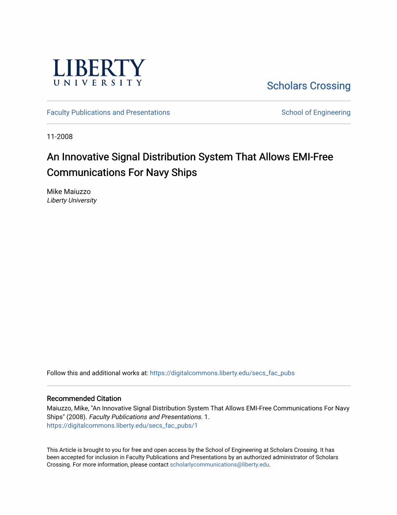
An Innovative Signal Distribution System That Allows EMI-Free Communications For Navy Ships
Ted Harwood, Sentel CorporationRich Adams, SPAWAR Systems Center, Pacific
Mike Maiuzzo, Liberty University
Page 2
BACKGROUNDBACKGROUNDNavy Ship Communications Systems Have Cosite EMI Problems Due to:– Adjacent-Signal EMI
Receiver Nonlinear DesensitizationCross ModulationReciprocal MixingTransmitter Noise
– Out-of-Band EMITransmitter Spurious Emissions/HarmonicsReceiver Spurious Responses
– Intermodulation ProductsStructural Generated IM ProductsReceiver IM ProductsTransmitter IM Products
Presentation Title
Speaker Name
Page 3
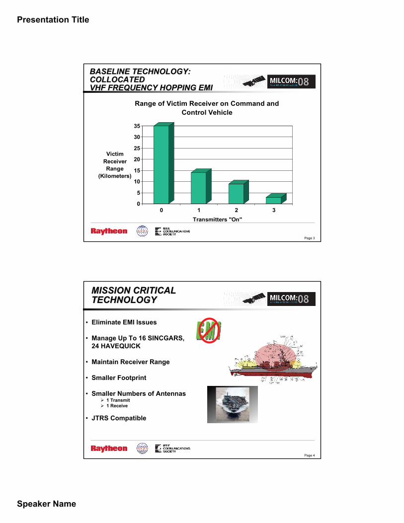
BASELINE TECHNOLOGY: BASELINE TECHNOLOGY: COLLOCATEDCOLLOCATEDVHF FREQUENCY HOPPING EMIVHF FREQUENCY HOPPING EMI
0
5
10
15
20
25
30
35
Victim Receiver Range
(Kilometers)
0 1 2 3Transmitters "On"
Range of Victim Receiver on Command and Control Vehicle
Page 4
MISSION CRITICAL MISSION CRITICAL TECHNOLOGYTECHNOLOGY
• Eliminate EMI Issues
• Manage Up To 16 SINCGARS, 24 HAVEQUICK
• Maintain Receiver Range
• Smaller Footprint
• Smaller Numbers of Antennas1 Transmit1 Receive
• JTRS Compatible
Presentation Title
Speaker Name
Page 5
RF DISTRIBUTION RF DISTRIBUTION GENESISGENESIS
SENTEL IRAD In Collaboration With SPAWAR FOR VHF SINCGARS (1999 – 2003)
SPAWAR SBIR PH I/II/III FOR UHF LOS/HAVE QUICK (2004 –Present)
Page 6
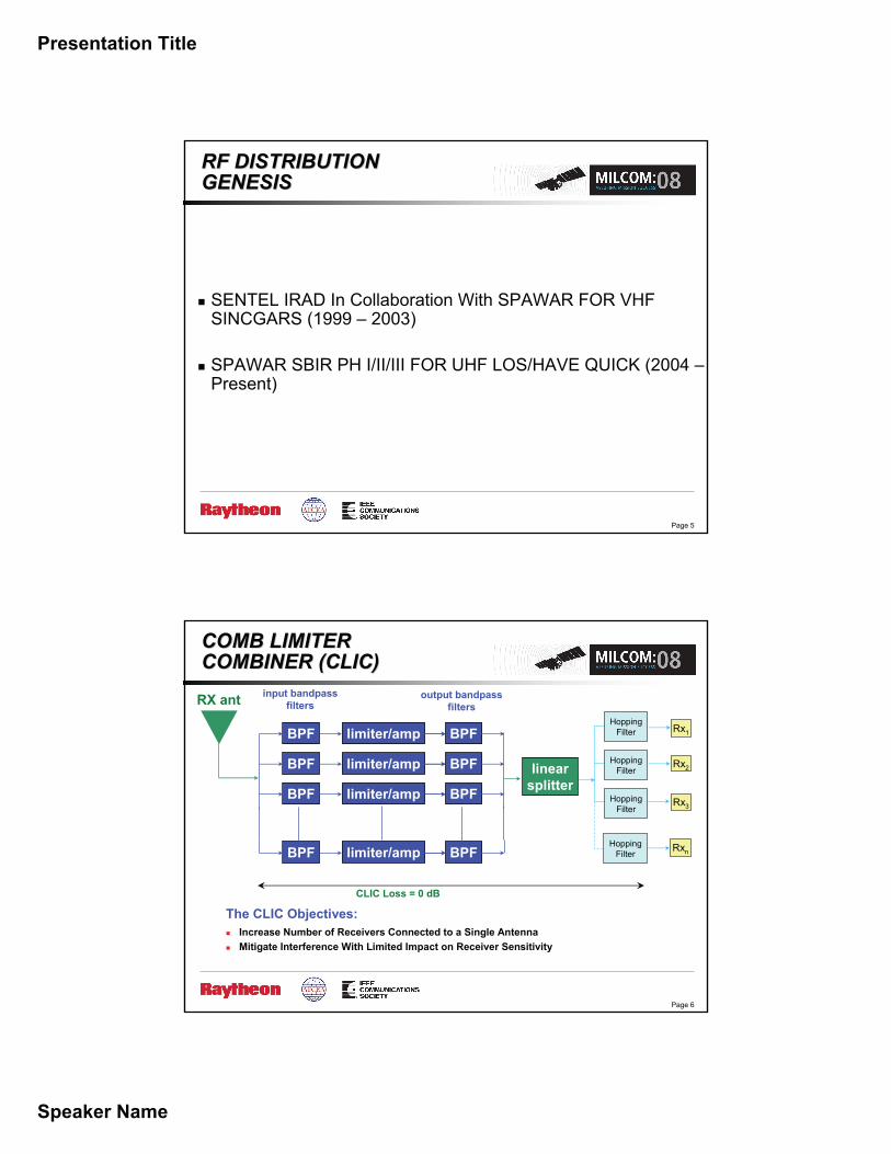
COMB LIMITER COMB LIMITER COMBINER (CLIC)COMBINER (CLIC)
The CLIC Objectives:Increase Number of Receivers Connected to a Single AntennaMitigate Interference With Limited Impact on Receiver Sensitivity
BPF
BPF BPFlimiter/amp
BPF BPFlimiter/amp
BPF BPFlimiter/amp
BPFlimiter/amp
linearsplitter
RX ant input bandpassfilters
output bandpassfilters
CLIC Loss = 0 dB
Rx1
HoppingFilter
HoppingFilter
HoppingFilter
HoppingFilter
Rx2
Rx3
Rxn
Presentation Title
Speaker Name
Page 7
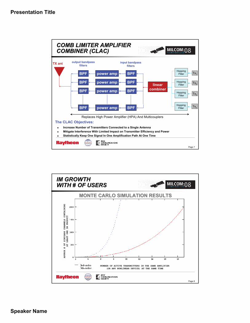
COMB LIMITER AMPLIFIERCOMB LIMITER AMPLIFIERCOMBINER (CLAC)COMBINER (CLAC)
Tx1
Tx2
Tx3
Txn
output bandpassfilters
BPF BPFpower amp
BPF BPFpower amp
BPF BPFpower amp
BPF BPFpower amp
linear combiner
TX ant input bandpassfilters
HoppingFilter
HoppingFilter
HoppingFilter
HoppingFilter
Replaces High Power Amplifier (HPA) And MulticouplersThe CLAC Objectives:
Increase Number of Transmitters Connected to a Single AntennaMitigate Interference With Limited Impact on Transmitter Efficiency and PowerStatistically Keep One Signal In One Amplification Path At One Time
Page 8
IM GROWTH IM GROWTH WITH # OF USERSWITH # OF USERS
MONTE CARLO SIMULATION RESULTSMONTE CARLO SIMULATION RESULTS
NUMBER OF ACTIVE TRANSMITTERS IN THE SAME AMPLIFIER (OR ANY NONLINEAR DEVICE) AT THE SAME TIME
APPROX # OF SINCGARS CHANNELS CONTAINING
AT LEAST ONE IM PRODUCT
Presentation Title
Speaker Name
Page 9
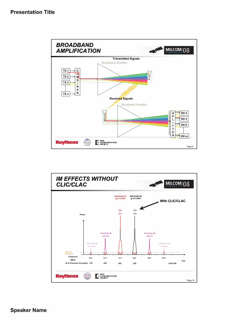
BROADBAND BROADBAND AMPLIFICATIONAMPLIFICATION
Transmitted Signals
TX n
TX 1 COMBINER
TX 2
TX 3
Broadband Amplifier
Broadband Amplifier
Received Signals
RX m
RX 4SPLITTER
RX 5
RX 6
Page 10
Receiver Threshold
(12) (26) (12)(26)(80) (80)(# of Channels Occupied)Total(236)
Fifth Order IM
(3F1-2F2)
Third Order IM
(2F1-F2)
Third Order IM
(2F2-F1)
Fifth Order IM
(3F2-2F1)
TX2
(F2)
SINCGARS #2@ 43.5 MHz
TX1
(F1)
SINCGARS #1 @ 37.5 MHz
Power
37.531.5 55.549.543.525.5Frequency
(MHz)
With CLIC/CLACWith CLIC/CLAC
IM EFFECTS WITHOUT IM EFFECTS WITHOUT CLIC/CLACCLIC/CLAC
(45) (45) Total (90)
Presentation Title
Speaker Name
Page 11
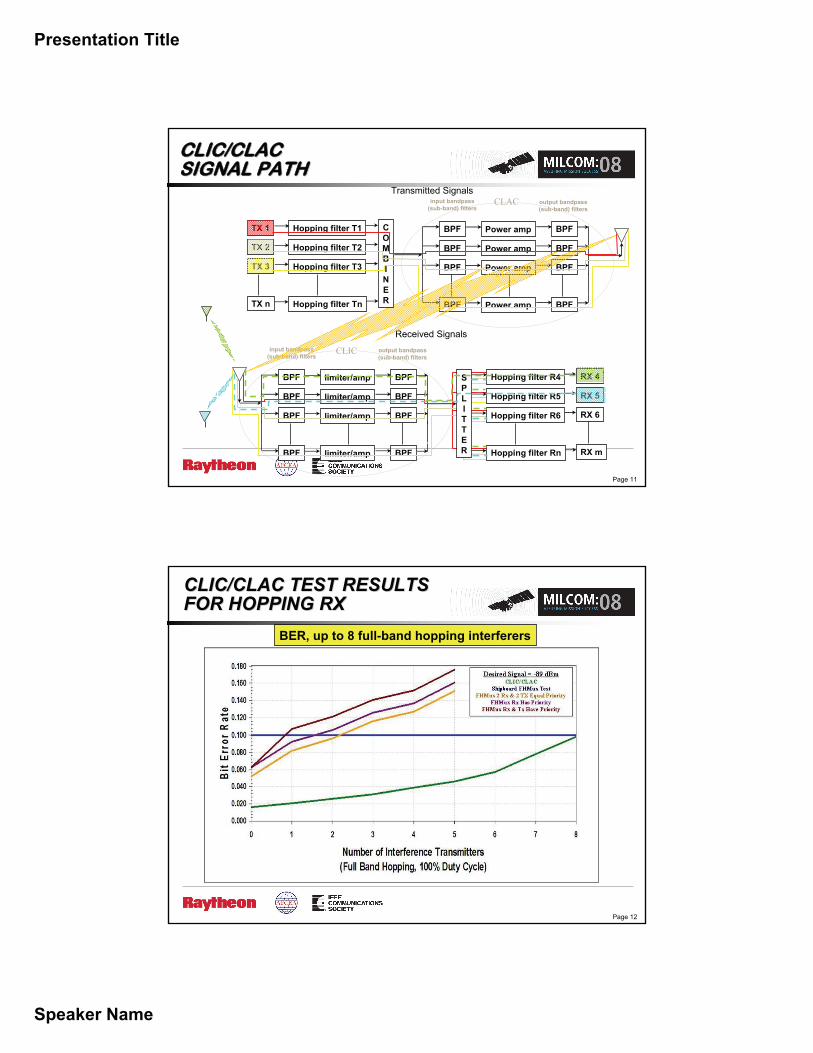
Transmitted Signals
Received Signals
CLAC
BPF
BPF BPFPower amp
BPF BPFPower amp
BPF BPFPower amp
BPFPower amp
input bandpass(sub-band) filters
output bandpass(sub-band) filters
BPF
BPF BPFlimiter/amp
BPF BPFlimiter/amp
BPF BPFlimiter/amp
BPFlimiter/amp
input bandpass(sub-band) filters
output bandpass(sub-band) filters
CLIC
TX n
TX 1 COMBINER
Hopping filter T1
TX 2 Hopping filter T2
TX 3 Hopping filter T3
Hopping filter Tn
RX m
RX 4SPLITTER
RX 5
RX 6
Hopping filter R4
Hopping filter R5
Hopping filter R6
Hopping filter Rn
CLIC/CLAC CLIC/CLAC SIGNAL PATHSIGNAL PATH
Page 12
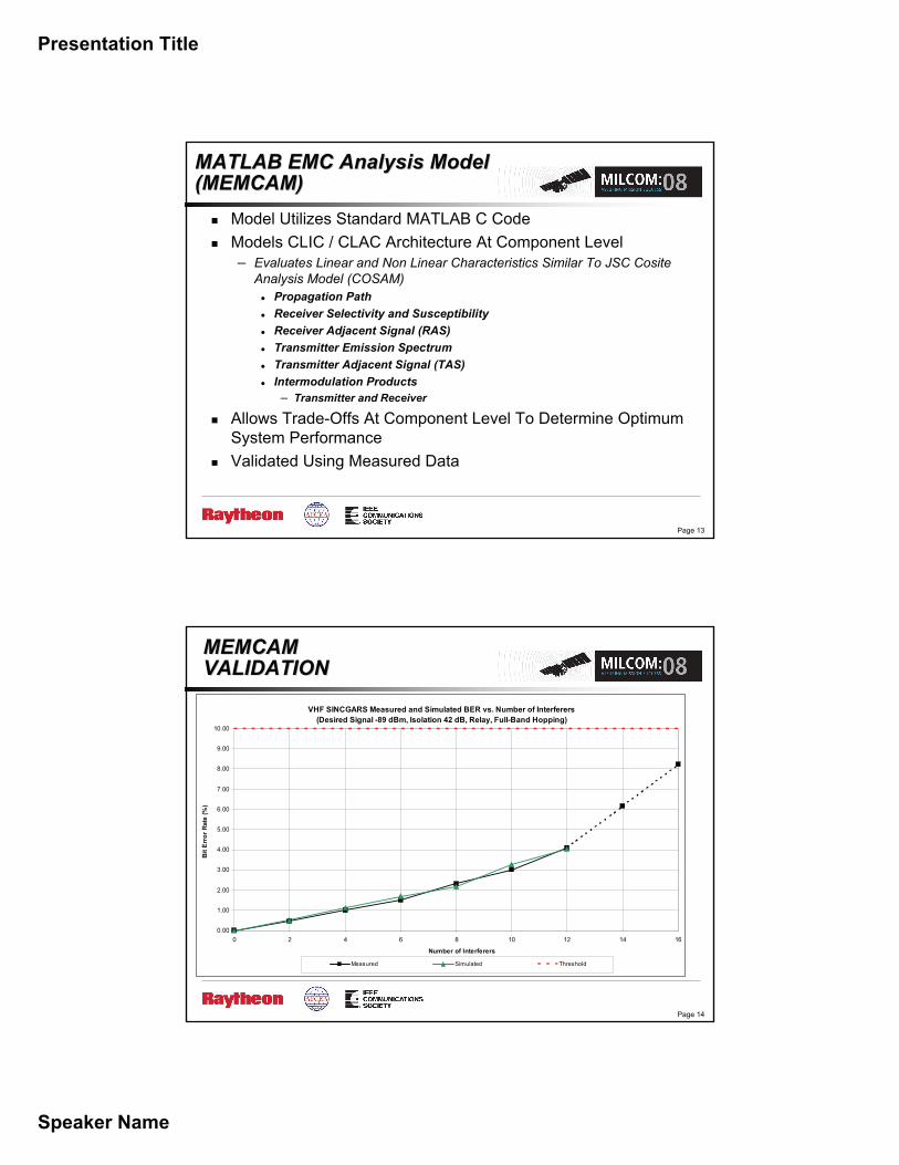
CLIC/CLAC TEST RESULTS CLIC/CLAC TEST RESULTS FOR HOPPING RXFOR HOPPING RX
BER, up to 8 full-band hopping interferers
Presentation Title
Speaker Name
Page 13
MATLAB EMC Analysis ModelMATLAB EMC Analysis Model(MEMCAM) (MEMCAM)
Model Utilizes Standard MATLAB C CodeModels CLIC / CLAC Architecture At Component Level– Evaluates Linear and Non Linear Characteristics Similar To JSC Cosite
Analysis Model (COSAM)Propagation PathReceiver Selectivity and SusceptibilityReceiver Adjacent Signal (RAS)Transmitter Emission SpectrumTransmitter Adjacent Signal (TAS)Intermodulation Products– Transmitter and Receiver
Allows Trade-Offs At Component Level To Determine Optimum System PerformanceValidated Using Measured Data
Page 14
MEMCAMMEMCAMVALIDATIONVALIDATION
VHF SINCGARS Measured and Simulated BER vs. Number of Interferers(Desired Signal -89 dBm, Isolation 42 dB, Relay, Full-Band Hopping)
0.00
1.00
2.00
3.00
4.00
5.00
6.00
7.00
8.00
9.00
10.00
0 2 4 6 8 10 12 14 16
Number of Interferers
Bit E
rror
Rat
e (%
)
Measured Simulated Threshold

Presentation Title
Speaker Name
Page 15
RANGE RANGE IMPROVEMENTIMPROVEMENT
05
101520253035
Victim Receiver Range
(Kilometers)
0 2 4 6 8 10 12 14 16Radios In Relay (50% Duty Cycle)
Range of Victim Receiver compared to the Number of Transmitters Operating on an Amphib
No Multiplexer With Legacy* With CLIC & CLAC**
*Maximum shipboard range 25 km, only one hopping radio per antenna (4 antennas for 16 radios)* *All radios hopping (2 antennas, 1 TX, 1 RX)
Page 16
LEGACY AMPHIB LEGACY AMPHIB LOS COMMSLOS COMMS
16 UHF Antennas
8 LOS
2 HQ
4 Tactical
(2 Spare)
5 VHF Antennas
4 Tactical
(1 Spare)
Presentation Title
Speaker Name
Page 17
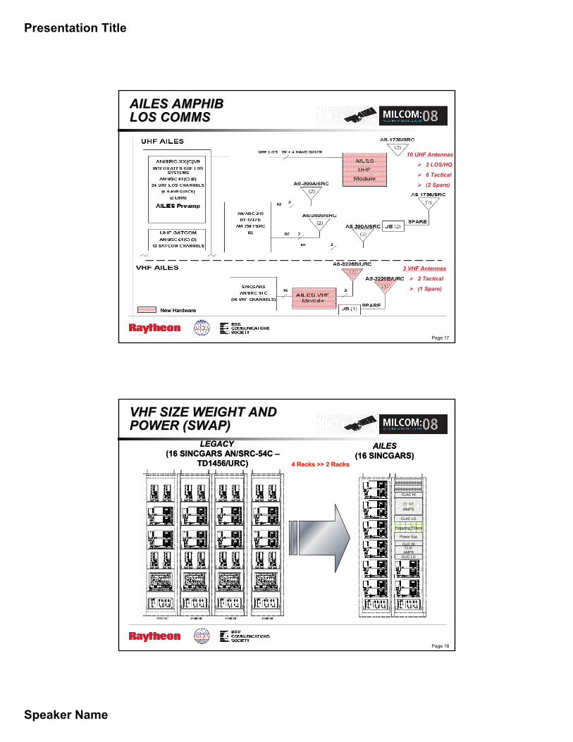
AILES AMPHIB AILES AMPHIB LOS COMMSLOS COMMS
New HardwareNew Hardware
10 UHF Antennas
2 LOS/HQ
6 Tactical
(2 Spare)
3 VHF Antennas
2 Tactical
(1 Spare)
Page 18
VHF SIZE WEIGHT AND VHF SIZE WEIGHT AND POWER (SWAP)POWER (SWAP)
LEGACY(16 SINCGARS AN/SRC-54C –
TD1456/URC)
AILES(16 SINCGARS)
4 Racks >> 2 Racks
CLAC HI
CLACAMPS
Hopping Filters
Power Sup
CLIC HICLIC
AMPSCLIC LO
CLAC LO
LEGACY(16 SINCGARS AN/SRC-54C –
TD1456/URC)
AILES(16 SINCGARS)
4 Racks >> 2 Racks
CLAC HI
CLACAMPS
Hopping Filters
Power Sup
CLIC HICLIC
AMPSCLIC LO
CLAC LO
CLAC HI
CLACAMPSCLACAMPS
Hopping Filters
Power Sup
CLIC HICLIC
AMPSCLIC
AMPSCLIC LO
CLAC LO
Presentation Title
Speaker Name
Page 19
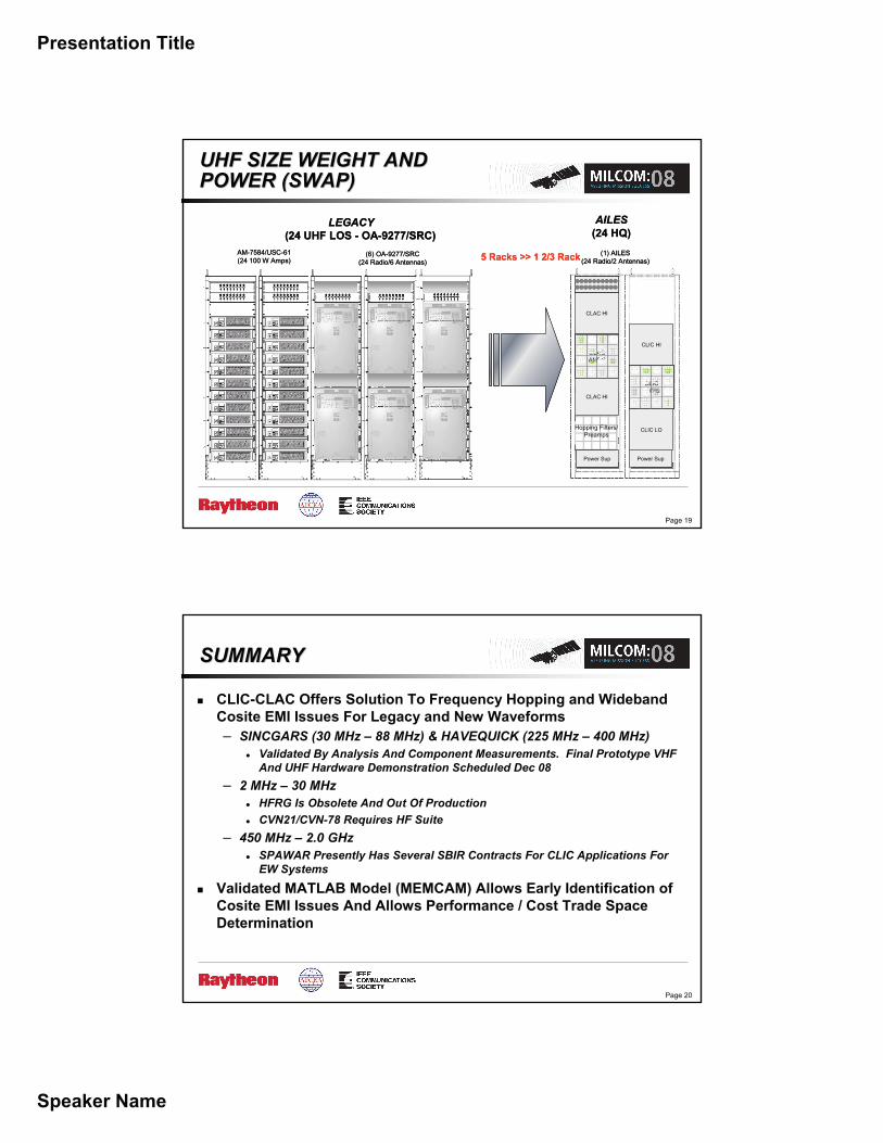
UHF SIZE WEIGHT AND UHF SIZE WEIGHT AND POWER (SWAP)POWER (SWAP)
AILES(24 HQ)
5 Racks >> 1 2/3 RackAM-7584/USC-61(24 100 W Amps)
(6) OA-9277/SRC(24 Radio/6 Antennas)
LEGACY(24 UHF LOS - OA-9277/SRC)
Hopping Filters/Preamps
Power Sup
CLACAMPS
(1) AILES(24 Radio/2 Antennas)
Power Sup
CLIC LO
CLICAMPS
CLIC HI
CLAC HI
CLAC HI
AILES(24 HQ)
5 Racks >> 1 2/3 RackAM-7584/USC-61(24 100 W Amps)
(6) OA-9277/SRC(24 Radio/6 Antennas)
LEGACY(24 UHF LOS - OA-9277/SRC)
Hopping Filters/Preamps
Power Sup
CLACAMPSCLACAMPS
(1) AILES(24 Radio/2 Antennas)
Power Sup
CLIC LO
CLICAMPSCLIC
AMPS
CLIC HI
CLAC HI
CLAC HI
Page 20
SUMMARYSUMMARY
CLIC-CLAC Offers Solution To Frequency Hopping and Wideband Cosite EMI Issues For Legacy and New Waveforms– SINCGARS (30 MHz – 88 MHz) & HAVEQUICK (225 MHz – 400 MHz)
Validated By Analysis And Component Measurements. Final Prototype VHF And UHF Hardware Demonstration Scheduled Dec 08
– 2 MHz – 30 MHzHFRG Is Obsolete And Out Of ProductionCVN21/CVN-78 Requires HF Suite
– 450 MHz – 2.0 GHzSPAWAR Presently Has Several SBIR Contracts For CLIC Applications For EW Systems
Validated MATLAB Model (MEMCAM) Allows Early Identification of Cosite EMI Issues And Allows Performance / Cost Trade Space Determination