Embed Size (px)
Citation preview

Slide 1
Digital CommunicationInter symbol interference, coherent and non-
coherent detectionLecture- 6 and 7
Ir. Muhamad Asvial, MSc., PhDCenter for Information and Communication Engineering Research (CICER)
Electrical Engineering Department - University of IndonesiaE-mail: [email protected]
http://www.ee.ui.ac.id/cicer

Slide 2
Bandpass modulation Bandpass modulation: The process of converting
data signal to a sinusoidal waveform where its amplitude, phase or frequency, or a combination of them, is varied in accordance with the transmitting data.
Bandpass signal:
where is the baseband pulse shape with energy .
We assume here (otherwise will be stated): is a rectangular pulse shape with unit energy. Gray coding is used for mapping bits to symbols. denotes average symbol energy given by
TtttitTEtgts ic
iTi 0 )()1(cos2)()(
)(tgT
)(tgT gE
sE
M
i is EM
E1
1

Slide 3
Demodulation and detection
• Demodulation: The receiver signal is converted to baseband, filtered and sampled.
• Detection: Sampled values are used for detection using a decision rule such as ML detection rule.
Nz
z1
z
T
0
)(1 t
T
0
)(tN)(tr
1z
Nz
z Decision circuits
(ML detector)m̂

Slide 4
Coherent detections
• Coherent detection– requires carrier phase recovery at the receiver and
hence, circuits to perform phase estimation.– Source of carrier-phase mismatch at the receiver:
• Propagation delay causes carrier-phase offset in the received signal.
• The oscillators at the receiver which generate the carrier signal, are not usually phased locked to the transmitted carrier.

Slide 5
Coherent detection ..
– Circuits such as Phase-Locked-Loop (PLL) are implemented at the receiver for carrier phase estimation ( ).
PLL
Oscillator 90 deg.
)()(cos2)()( tnttTEtgtr ii
iT ˆcos2
tT c
ˆsin2t
T c
Used by correlators
ˆ
I branch
Q branch

Slide 6
Bandpass Modulation Schemes
• One dimensional waveforms– Amplitude Shift Keying (ASK)– M-ary Pulse Amplitude Modulation (M-PAM)
• Two dimensional waveforms– M-ary Phase Shift Keying (M-PSK)– M-ary Quadrature Amplitude Modulation (M-QAM)
• Multidimensional waveforms– M-ary Frequency Shift Keying (M-FSK)

Slide 7
One dimensional modulation, demodulation and detection
• Amplitude Shift Keying (ASK) modulation:
tTEts c
ii cos2)(
cos2)(
,,1 )()(
1
1
ii
c
ii
Ea
tT
t
Mitats
)(1 t1s2s0 1E
“0” “1”On-off keying:

Slide 8
Example of bandpass modulation:Binary PAM

Slide 9
• Coherent detection of M-PAM
T
0
)(1 t
ML detector(Compare with M-1 thresholds))(tr 1z
m̂
One dimensional mod.,...–cont’d

Slide 10
Two dimensional mod.,…(MPSK)
• Coherent detection of MPSK
Compute Choose smallest
2
1arctanzz ̂
|ˆ| i
T
0
)(1 t
T
0
)(2 t)(tr
1z
2z
m̂

Slide 11
Two dimensional mod.,… (M-QAM)
• Coherent detection of M-QAM
T
0
)(1 t
ML detector1z
T
0
)(2 t
ML detector
)(tr
2z
m̂Parallel-to-serialconverter
s) threshold1 with (Compare M
s) threshold1 with (Compare M

Slide 12
Multi-dimensional mod.,…(M-FSK)
Mz
z1
z
T
0
)(1 t
T
0
)(tM)(tr
1z
Mz
zML detector:
Choose the largest element
in the observed vectorm̂

Slide 13
Non-coherent detection
• Non-coherent detection:– No need in a reference in phase with the received
carrier– Less complexity as compared to coherent detection at
the price of higher error rate.

Slide 14
Non-coherent detection …• Optimum differentially coherent detector
• Sub-optimum differentially coherent detector
» Performance degradation about 3 dB by using sub-optimum detector
T
0
)(1 t
)(tr m̂Decision
DelayT
T
0)(tr m̂Decision
DelayT

Slide 15
Non-coherent detection …
– Energy detection• Non-coherent detection for orthogonal signals (e.g. M-
FSK)
– Carrier-phase offset causes partial correlation between I and Q braches for each candidate signal.
– The received energy corresponding to each candidate signal is used for detection.

Slide 16
Non-coherent detection …
• Non-coherent detection of BFSK
T
0
)cos(/2 1tT
T
0)(tr
11z
12z
T
0
T
0
21z
22z
Decision stage:
)cos(/2 2 tT
)sin(/2 2 tT
)sin(/2 1tT
2
2
2
2 +
-
)(Tz
0ˆ ,0)( if1ˆ ,0)( if
mTzmTz
m̂
212
211 zz
222
221 zz

Slide 17
Error probability of bandpass modulation
• Before evaluating the error probability, it is important to remember that: – Type of modulation and detection ( coherent or non-coherent),
determines the structure of the decision circuits and hence the decision variable, denoted by z.
– The decision variable, z, is compared with M-1 thresholds, corresponding to M decision regions for detection purposes.
Nr
r1
r
T
0
)(1 t
T
0
)(tN)(tr
1r
Nr
rDecision CircuitsCompare z
with threshold.
m̂

Slide 18
Error probability …
• Non-coherent detection of BFSK
T
0
)cos(/2 1tT
T
0)(tr
11r
12r
T
0
T
0
21r
22r
Decision rule:
)cos(/2 2 tT
)sin(/2 2 tT
)sin(/2 1tT
2
2
2
2 +
-
z
0ˆ ,0)( if1ˆ ,0)( if
mTzmTz
m̂
212
2111 rrz
222
2212 rrz
21 zzz
Decision variable:Difference of envelopes

Slide 19
Error probability …
• Coherent detection of M-QAM …• M-QAM can be viewed as the combination of two
modulations on I and Q branches, respectively. • No error occurs if no error is detected on either I and Q branches.
Hence:• Considering the symmetry of the signal space and orthogonality of I
and Q branches:
PAMM
branches) Q and Ion detectederror noPr(1)(1)( MPMP CE
22 1I)on error Pr(no
Q)on error I)Pr(noon error Pr(nobranches) Q and Ion detectederror noPr(
MPE
0
2
1log3114)(
NE
MMQ
MMP b
E Average probability of symbol error for PAMM

Slide 20
Error probability …
• Coherent detection of MPSK …• The detector compares the phase of observation vector to M-1
thresholds.• Due to the circular symmetry of the signal space, we have:
where
• It can be shown that
dpPP
MMPMP
M
Mc
M
mmcCE )(1)(1)(11)(1)(
/
/ ˆ11
ss
MNEQMP s
Esin22)(
0
MNEMQMP b
Esinlog22)(
0
2or
2|| ;sinexp)cos(2)( 2
00ˆ
NE
NEp ss

Slide 21
Error probability …
• Coherent detection of M-FSK …• The dimensionality of signal space is M. An upper bound for
average symbol error probability can be obtained by using union bound. Hence
or, equivalently
0
1)(NEQMMP s
E
0
2log1)(N
EMQMMP bE

Slide 22
Bit error probability versus symbol error probability
• Number of bits per symbol • For orthogonal M-ary signaling (M-FSK)
• For M-PSK, M-PAM and M-QAM
21lim
12/
122 1
E
Bk
k
k
E
B
PP
MM
PP
Mk 2log
1for EE
B PkPP
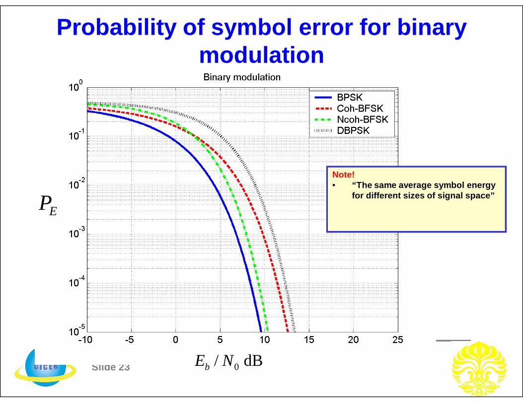
Slide 23
Probability of symbol error for binary modulation
EP
dB / 0NEb
Note!• “The same average symbol energy
for different sizes of signal space”

Slide 24
Probability of symbol error for M-PSK
EP
dB / 0NEb
Note!• “The same average symbol energy
for different sizes of signal space”

Slide 25
Probability of symbol error for M-FSK
EP
dB / 0NEb
Note!• “The same average symbol energy
for different sizes of signal space”

Slide 26
Probability of symbol error for M-PAM
EP
dB / 0NEb
Note!• “The same average symbol energy
for different sizes of signal space”

Slide 27
Probability of symbol error for M-QAM
EP
dB / 0NEb
Note!• “The same average symbol energy
for different sizes of signal space”


![Adaptive Resource Balanced Allocation Algorithm for Inter ... · inter-cell interference is Inter-Cell Interference Coordination (ICIC) [6]. Its major technique is Frequency Reuse,](https://img.pdfslide.net/doc/110x75/5fff02f74d96220ee55a274d/adaptive-resource-balanced-allocation-algorithm-for-inter-inter-cell-interference.jpg)