Embed Size (px)
Citation preview
Digital Control Unit- Installation, Operation & Maintenance
ALL BOSS PRESSURISATION EQUIPMENT MUST BE COMMISSIONED TO THE INDIVIDUAL SYSTEM REQUIREMENTS 01/10 RJAC
IMPORTANT INFORMATION
Environment
• It is not anticipated that this equipment will be exposed to adverse environmental conditions without additional protection. • Site the equipment in a frost free area. • Ensure that 100mm of clear access is available around the equipment with
500mm clear access at the front. • Flush the mains water supply pipe before connection to this equipment. • An inline filter must be fitted to the inlet of the equipment if the mains
water supply is suspected to contain debris. • Please refer to BS 7074 for the installation code of practice. • Do not use this equipment to fill a system unless otherwise stated; it is
designed to ‘top-up’ a system in the event of pressure loss due to de-aeration and minor system leakage.
Safety
• Electrical installation must be carried out by a competent person • WARNING – LIVE TERMINALS WITHIN THIS EQUIPMENT • Isolate the equipment before removing any covers • Do Not make any electrical adjustments to the equipment unless it is
isolated from the mains electrical supply • Do Not operate with the electrical covers removed • Do Not alter any internal pipe-work, this equipment is tested prior to
Dispatch. • Do Not obstruct and ventilation fans or apertures • Check supply voltage and overload protection is correct Lock-shield Valve
BOSS pressurisation equipment is supplied with a Lock-shield system connection valve (Not included on MX1-3E, MX2-3E, MX1-3HL, MX2-3HL or MDE units).
This valve acts as a system isolation valve, pressurisation unit drain valve and transducer connection point (Where fitted).
The Lock-shield valve is supplied in the normally closed position, this must be opened to allow system pressure to be monitored by the pressurisation equipment. To open remove the key, exposing the isolation valve spindle, open the valve (anticlockwise rotation) and replace cover (key).
Digital Control Unit- Installation, Operation & Maintenance
ALL BOSS PRESSURISATION EQUIPMENT MUST BE COMMISSIONED TO THE INDIVIDUAL SYSTEM REQUIREMENTS 01/10 RJAC
Installation
Remove the appropriate coverings. Ensure that the float valve is set to it lowest position. All pipework connections are to be made with appropriate proprietary
jointing compound. PTFE is not permitted. Connect the overflow pipework. Connect the mains water pipework. Connect the system pipework. Open the system isolation valve. (The Lockshield valve or the boilerfix
chrome plated valve (Boilerfix valves must be inline with the pipework to be open).
Check the break tank internal pump suction filter is present and clear. Connect the electrical supply to the fused connection block / fused spur as
appropriate. Connect the boiler to the boiler interlock connection / Common Alarm if
required. Commissioning
• Remove all covers • Connect overflow pipe-work and ensure a continuous fall to drain • Ensure the flow restrictor is installed in the float valve (Mini & Midi units) • Connect mains water supply to break tank float valve • Connect heating / chilled system to the system isolation valve • Connect mains electricity supply to unit, including provided earth
connection (Wiring is detailed separately for each unit) • Open the system isolation valve (1/4” Nickel Plated Ball Valve or ½”
Lockshield) • Program required pressure and alarm setpoints
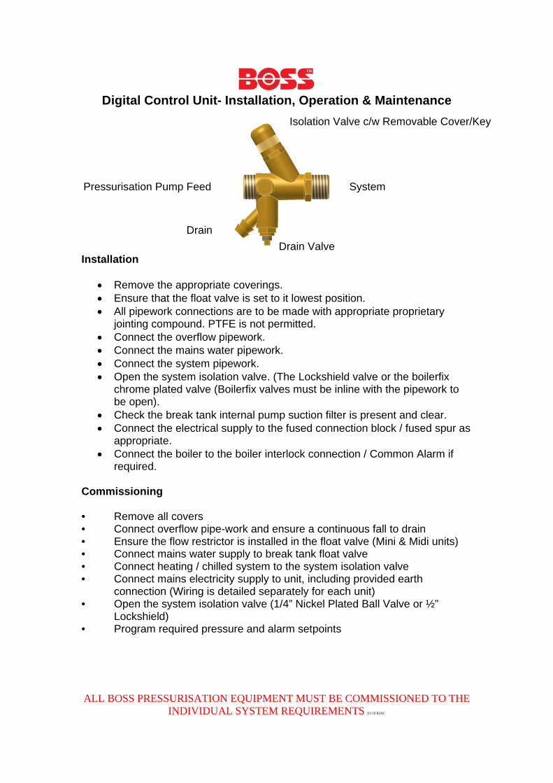
System
Isolation Valve c/w Removable Cover/Key
Drain Valve
Drain
Pressurisation Pump Feed
Digital Control Unit- Installation, Operation & Maintenance
ALL BOSS PRESSURISATION EQUIPMENT MUST BE COMMISSIONED TO THE INDIVIDUAL SYSTEM REQUIREMENTS 01/10 RJAC
Non Return Valves (NRV / Check Valves)
Non return valves must not be used between the system and the pressurisation unit. The only exception is when a single pressurisation unit is being used to supply two separate systems. This practice is not recommended as it removes the ability of the pressurisation unit to monitor a high pressure situation or to discriminate between the connected systems.
When supplying multiple systems it is common practice to isolate the systems using NRV’s.
This pressurisation equipment monitors the system pressure and replenishes as required, with an NRV in place rises in system pressure cannot be monitored. For initial commissioning of Digital Equipment an NRV must be bypassed to allow the pressurisation unit to ‘see’ system pressure.
Electrical Considerations Electrical installation must be carried out by a trained and competent person. Isolate the unit from the electrical mains supply before removing any covers, or servicing the unit. Unless otherwise stated the equipment requires a 230v, 50Hz single phase electrical supply.
Digital Control Unit- Installation, Operation & Maintenance
ALL BOSS PRESSURISATION EQUIPMENT MUST BE COMMISSIONED TO THE INDIVIDUAL SYSTEM REQUIREMENTS 01/10 RJAC
Maintenance
Before carrying out any maintenance please remember to first electrically isolate the equipment and then hydraulically isolate the equipment.
Please ensure that competent trained engineers are used to carry out any service or maintenance work. It is recommended that the system as a whole is serviced and inspected annually. At that time the gas charge within the system expansion vessel (if appropriate) should be checked and verified as equal to the cold fill pressure set on this pressurisation unit.
The cold fill pressure should be equal to the static height of the system +0.3bar, to ensure air is capable of being purged from the uppermost points of the system.
The pump, float valve (ball cock), low level switch and alarm operations should also be checked at this interval as a minimum. Check the internal filters within the break tank are present and clear. A visual check of the equipment for corrosion or damage should also be carried out and noted. All alarm and diagnostic counters should be recorded and compared to the previous service or commissioning for analysis of the system as a whole. This equipment is designed to provide periodic water top up in the event of minor losses from a sealed heating or chilled system. The flow rates of the pumps used must be taken into consideration for estimating water loss over the service period. Excessive pump activations or hour run are an indication of a system problem and should be investigated. Please consider the environment and report / rectify any significant water losses.
Maintenance Timeline
Commissioning by trained engineers Day 1
Check alarms and counters First 6 months
Service and Inspection Annually thereafter
Digital Control Unit- Installation, Operation & Maintenance
ALL BOSS PRESSURISATION EQUIPMENT MUST BE COMMISSIONED TO THE INDIVIDUAL SYSTEM REQUIREMENTS 01/10 RJAC
Warranty
This equipment is covered against manufacturing defects for 12 months from date of purchase from BSS.
This warranty covers the replacement of parts or products, verified as having a manufacturing defect, when inspected at the St Helens factory.
BSS reserves the right to inspect an installation to verify that the equipment has been installed in accordance with the written instructions.
Any modifications to the supplied equipment must be approved in writing by BSS, failure to do so will invalidate the warranty.
Site Visit
Before requesting a site visit, the following information must be made available to the BSS sales team.
• Serial number of the equipment. Failure to verify the serial number at the time of visit will invalidate the warranty • A purchase order to cover the work in the event that no manufacturing
defect if found. (This must be the direct customer of BSS). • A site contact name and number • A full description of the alleged fault Liability
BSS can only respond to warranty queries from its direct customer. If in doubt, please contact your installer to establish the supply chain.
Digital Control Unit- Installation, Operation & Maintenance
ALL BOSS PRESSURISATION EQUIPMENT MUST BE COMMISSIONED TO THE INDIVIDUAL SYSTEM REQUIREMENTS 01/10 RJAC
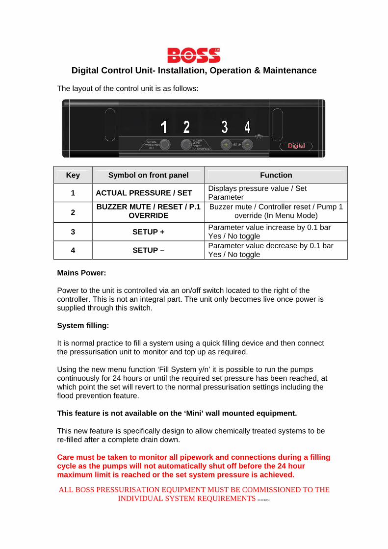
The layout of the control unit is as follows:
Key Symbol on front panel Function
1 ACTUAL PRESSURE / SET Displays pressure value / Set Parameter
2 BUZZER MUTE / RESET / P.1
OVERRIDE Buzzer mute / Controller reset / Pump 1
override (In Menu Mode)
3 SETUP + Parameter value increase by 0.1 bar Yes / No toggle
4 SETUP – Parameter value decrease by 0.1 bar Yes / No toggle
Mains Power:
Power to the unit is controlled via an on/off switch located to the right of the controller. This is not an integral part. The unit only becomes live once power is supplied through this switch.
System filling:
It is normal practice to fill a system using a quick filling device and then connect the pressurisation unit to monitor and top up as required.
Using the new menu function ‘Fill System y/n’ it is possible to run the pumps continuously for 24 hours or until the required set pressure has been reached, at which point the set will revert to the normal pressurisation settings including the flood prevention feature.
This feature is not available on the ‘Mini’ wall mounted equipment.
This new feature is specifically design to allow chemically treated systems to be re-filled after a complete drain down.
Care must be taken to monitor all pipework and connections during a filling cycle as the pumps will not automatically shut off before the 24 hour maximum limit is reached or the set system pressure is achieved.
Digital Control Unit- Installation, Operation & Maintenance
ALL BOSS PRESSURISATION EQUIPMENT MUST BE COMMISSIONED TO THE INDIVIDUAL SYSTEM REQUIREMENTS 01/10 RJAC
Digital Control Unit- Installation, Operation & Maintenance
ALL BOSS PRESSURISATION EQUIPMENT MUST BE COMMISSIONED TO THE INDIVIDUAL SYSTEM REQUIREMENTS 01/10 RJAC
Accessing Programme Parameters And Stored Information:
To enter the program and to set the unit up a password needs to be entered. Press + & - keys simultaneously and hold for 2 seconds. Then release. Then enter the code 0823. + to count up, - to count down. To index to the next digit press the Set key. To accept the code press the set key again. Interpreting The On Screen Information:
‘Cold Fill’ appears followed by a number, this shows the desired fill pressure. By using +/- keys the correct pressure can be entered. (Typically 1.0 Bar). Press and hold P.1 Override button to manually test pump 1 at this menu point (Pump 1 only). By pressing the Set key it accepts the set pressure and indexes to the next program item;
‘High Set’ appears followed by a number, this shows the high pressure alarm setting. By using +/- keys the correct pressure can be entered. (Typically 3.0 Bar). By pressing the Set key it accepts the high pressure alarm setting and indexes to the next program item;
‘Low Set’ appears followed by a number, this shows the low pressure alarm. By using +/- keys the correct pressure can be entered. (Typically 0.5 Bar). By pressing the Set key it accepts the low pressure alarm setting and indexes to the next program item;
‘Differential’ appears followed by a number, this shows the pump on/off differential. By using +/- keys the correct differential can be entered. (Typically 0.2 Bar). This variable is the difference between the set pressure and the pressure that the pump will activate (e.g. 1.0 bar Cold Fill pressure minus 0.2 bar Differential gives a pump start pressure of 0.8 bar). By pressing the Set key it accepts the setting and indexes to the next program item;
‘Flood Limit’ appears followed by a number, this shows the maximum pump run time. By using +/- keys the required time can be entered in 10 minute increments (Typically set at 10 minutes). By pressing the Set key it accepts the time setting and indexes to the next program item; ‘Pump 1 Count’ appears followed by a number. This is the number of times pump 1 has run / charged the system. The display can show 9999 recorded pump runs. By pressing the Set key it indexes to the next program item; ‘Pump 1 Hours’ appears followed by a number. This is the cumulative number of hours pump 1 has run / charged the system. The display can show 999.9 hours. By pressing the Set key it indexes to the next programme item;
Digital Control Unit- Installation, Operation & Maintenance
ALL BOSS PRESSURISATION EQUIPMENT MUST BE COMMISSIONED TO THE INDIVIDUAL SYSTEM REQUIREMENTS 01/10 RJAC
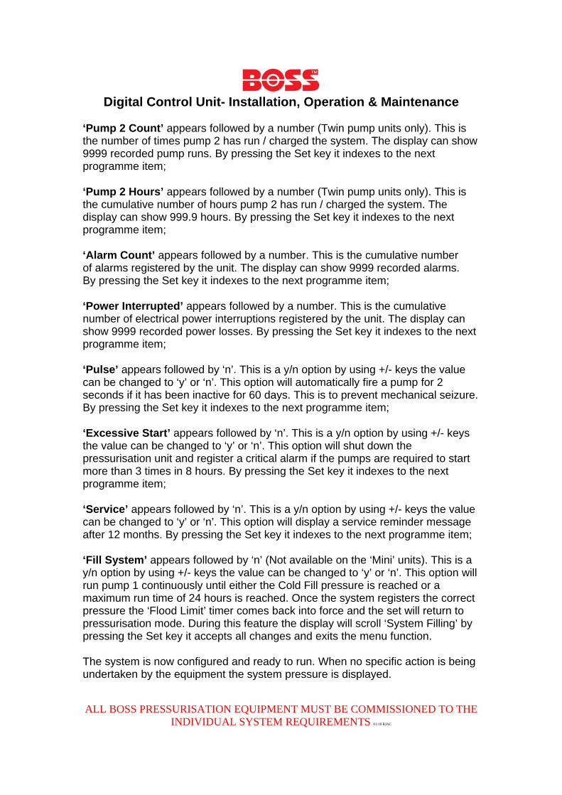
‘Pump 2 Count’ appears followed by a number (Twin pump units only). This is the number of times pump 2 has run / charged the system. The display can show 9999 recorded pump runs. By pressing the Set key it indexes to the next programme item;
‘Pump 2 Hours’ appears followed by a number (Twin pump units only). This is the cumulative number of hours pump 2 has run / charged the system. The display can show 999.9 hours. By pressing the Set key it indexes to the next programme item;
‘Alarm Count’ appears followed by a number. This is the cumulative number of alarms registered by the unit. The display can show 9999 recorded alarms. By pressing the Set key it indexes to the next programme item;
‘Power Interrupted’ appears followed by a number. This is the cumulative number of electrical power interruptions registered by the unit. The display can show 9999 recorded power losses. By pressing the Set key it indexes to the next programme item;
‘Pulse’ appears followed by ‘n’. This is a y/n option by using +/- keys the value can be changed to ‘y’ or ‘n’. This option will automatically fire a pump for 2 seconds if it has been inactive for 60 days. This is to prevent mechanical seizure. By pressing the Set key it indexes to the next programme item;
‘Excessive Start’ appears followed by ‘n’. This is a y/n option by using +/- keys the value can be changed to ‘y’ or ‘n’. This option will shut down the pressurisation unit and register a critical alarm if the pumps are required to start more than 3 times in 8 hours. By pressing the Set key it indexes to the next programme item;
‘Service’ appears followed by ‘n’. This is a y/n option by using +/- keys the value can be changed to ‘y’ or ‘n’. This option will display a service reminder message after 12 months. By pressing the Set key it indexes to the next programme item; ‘Fill System’ appears followed by ‘n’ (Not available on the ‘Mini’ units). This is a y/n option by using +/- keys the value can be changed to ‘y’ or ‘n’. This option will run pump 1 continuously until either the Cold Fill pressure is reached or a maximum run time of 24 hours is reached. Once the system registers the correct pressure the ‘Flood Limit’ timer comes back into force and the set will return to pressurisation mode. During this feature the display will scroll ‘System Filling’ by pressing the Set key it accepts all changes and exits the menu function. The system is now configured and ready to run. When no specific action is being undertaken by the equipment the system pressure is displayed.
Digital Control Unit- Installation, Operation & Maintenance
ALL BOSS PRESSURISATION EQUIPMENT MUST BE COMMISSIONED TO THE INDIVIDUAL SYSTEM REQUIREMENTS 01/10 RJAC
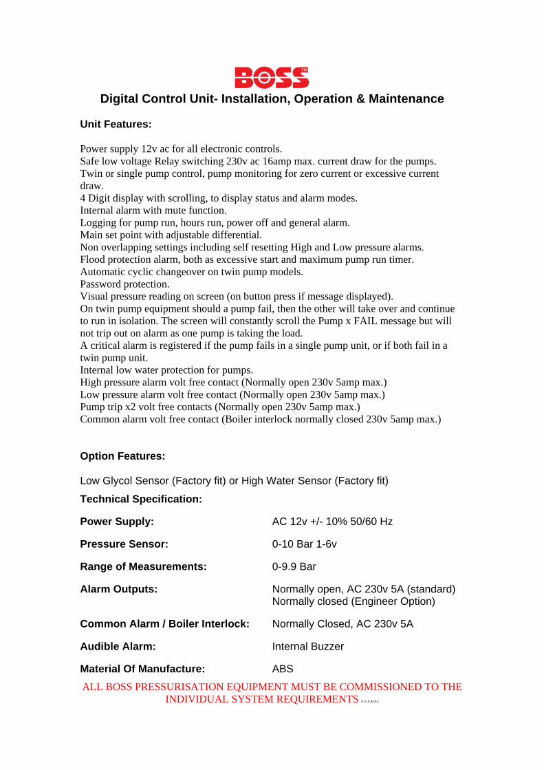
Unit Features:
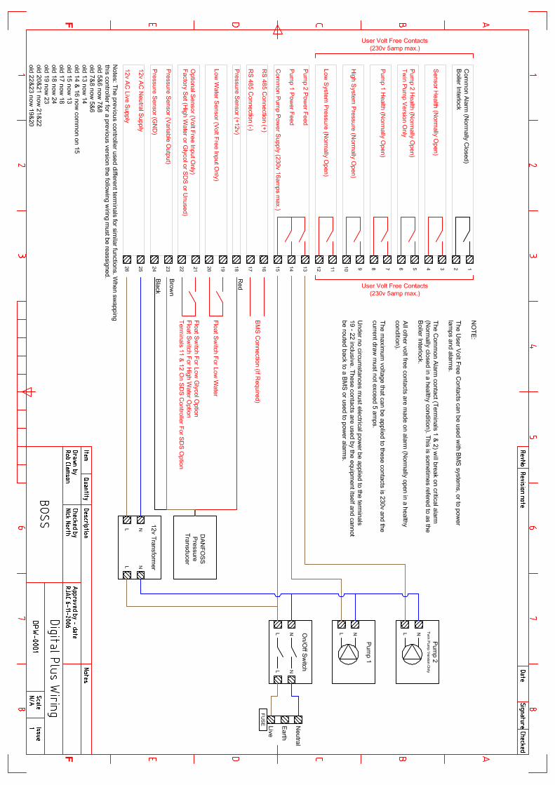
Power supply 12v ac for all electronic controls. Safe low voltage Relay switching 230v ac 16amp max. current draw for the pumps. Twin or single pump control, pump monitoring for zero current or excessive current draw. 4 Digit display with scrolling, to display status and alarm modes. Internal alarm with mute function. Logging for pump run, hours run, power off and general alarm. Main set point with adjustable differential. Non overlapping settings including self resetting High and Low pressure alarms. Flood protection alarm, both as excessive start and maximum pump run timer. Automatic cyclic changeover on twin pump models. Password protection. Visual pressure reading on screen (on button press if message displayed). On twin pump equipment should a pump fail, then the other will take over and continue to run in isolation. The screen will constantly scroll the Pump x FAIL message but will not trip out on alarm as one pump is taking the load. A critical alarm is registered if the pump fails in a single pump unit, or if both fail in a twin pump unit. Internal low water protection for pumps. High pressure alarm volt free contact (Normally open 230v 5amp max.) Low pressure alarm volt free contact (Normally open 230v 5amp max.) Pump trip x2 volt free contacts (Normally open 230v 5amp max.) Common alarm volt free contact (Boiler interlock normally closed 230v 5amp max.)
Option Features:
Low Glycol Sensor (Factory fit) or High Water Sensor (Factory fit)
Technical Specification:
Power Supply: AC 12v +/- 10% 50/60 Hz
Pressure Sensor: 0-10 Bar 1-6v
Range of Measurements: 0-9.9 Bar
Alarm Outputs: Normally open, AC 230v 5A (standard) Normally closed (Engineer Option)
Common Alarm / Boiler Interlock: Normally Closed, AC 230v 5A
Audible Alarm: Internal Buzzer
Material Of Manufacture: ABS
Digital Control Unit- Installation, Operation & Maintenance
ALL BOSS PRESSURISATION EQUIPMENT MUST BE COMMISSIONED TO THE INDIVIDUAL SYSTEM REQUIREMENTS 01/10 RJAC
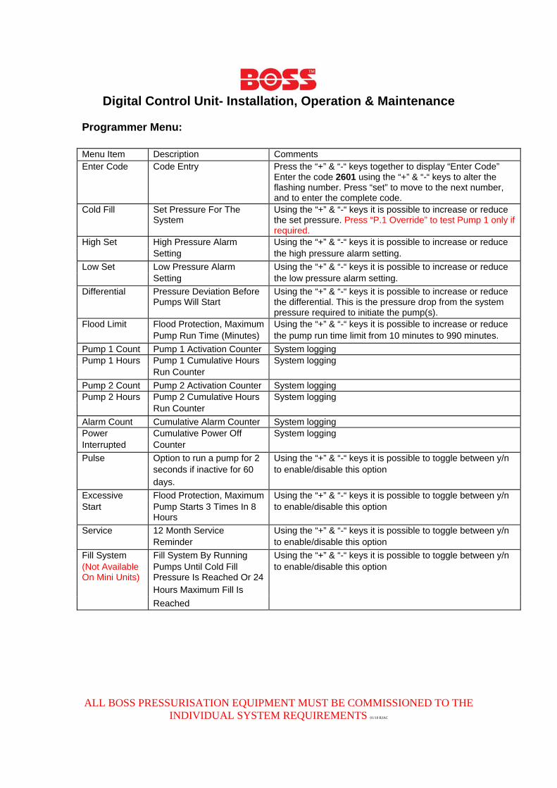
Programmer Menu:
Menu Item Description Comments Enter Code Code Entry Press the “+” & “-“ keys together to display “Enter Code”
Enter the code 2601 using the “+” & “-“ keys to alter the flashing number. Press “set” to move to the next number, and to enter the complete code.
Cold Fill Set Pressure For The System
Using the “+” & “-“ keys it is possible to increase or reduce the set pressure. Press “P.1 Override” to test Pump 1 only if required.
High Set High Pressure Alarm Using the “+” & “-“ keys it is possible to increase or reduce
Setting the high pressure alarm setting.
Low Set Low Pressure Alarm Using the “+” & “-“ keys it is possible to increase or reduce
Setting the low pressure alarm setting.
Differential Pressure Deviation Before Pumps Will Start
Using the “+” & “-“ keys it is possible to increase or reduce the differential. This is the pressure drop from the system pressure required to initiate the pump(s).
Flood Limit Flood Protection, Maximum Using the “+” & “-“ keys it is possible to increase or reduce
Pump Run Time (Minutes) the pump run time limit from 10 minutes to 990 minutes.
Pump 1 Count Pump 1 Activation Counter System logging Pump 1 Hours Pump 1 Cumulative Hours System logging
Run Counter Pump 2 Count Pump 2 Activation Counter System logging Pump 2 Hours Pump 2 Cumulative Hours System logging
Run Counter Alarm Count Cumulative Alarm Counter System logging Power Cumulative Power Off System logging Interrupted Counter Pulse Option to run a pump for 2 Using the “+” & “-“ keys it is possible to toggle between y/n
seconds if inactive for 60 to enable/disable this option
days. Excessive Flood Protection, Maximum Using the “+” & “-“ keys it is possible to toggle between y/n Start Pump Starts 3 Times In 8 to enable/disable this option Hours Service 12 Month Service Using the “+” & “-“ keys it is possible to toggle between y/n
Reminder to enable/disable this option
Fill System Fill System By Running Using the “+” & “-“ keys it is possible to toggle between y/n (Not Available Pumps Until Cold Fill to enable/disable this option On Mini Units) Pressure Is Reached Or 24 Hours Maximum Fill Is Reached
Digital Control Unit- Installation, Operation & Maintenance
ALL BOSS PRESSURISATION EQUIPMENT MUST BE COMMISSIONED TO THE INDIVIDUAL SYSTEM REQUIREMENTS 01/10 RJAC
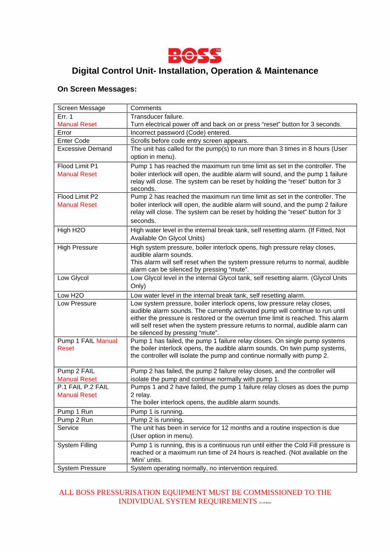
On Screen Messages:
Screen Message Comments Err. 1 Transducer failure. Manual Reset Turn electrical power off and back on or press “reset” button for 3 seconds. Error Incorrect password (Code) entered. Enter Code Scrolls before code entry screen appears. Excessive Demand The unit has called for the pump(s) to run more than 3 times in 8 hours (User
option in menu).
Flood Limit P1 Pump 1 has reached the maximum run time limit as set in the controller. The Manual Reset boiler interlock will open, the audible alarm will sound, and the pump 1 failure relay will close. The system can be reset by holding the “reset” button for 3
seconds. Flood Limit P2 Pump 2 has reached the maximum run time limit as set in the controller. The Manual Reset boiler interlock will open, the audible alarm will sound, and the pump 2 failure relay will close. The system can be reset by holding the “reset” button for 3
seconds.
High H2O High water level in the internal break tank, self resetting alarm. (If Fitted, Not
Available On Glycol Units)
High Pressure High system pressure, boiler interlock opens, high pressure relay closes, audible alarm sounds.
This alarm will self reset when the system pressure returns to normal, audible alarm can be silenced by pressing “mute”.
Low Glycol Low Glycol level in the internal Glycol tank, self resetting alarm. (Glycol Units
Only)
Low H2O Low water level in the internal break tank, self resetting alarm. Low Pressure Low system pressure, boiler interlock opens, low pressure relay closes,
audible alarm sounds. The currently activated pump will continue to run until either the pressure is restored or the overrun time limit is reached. This alarm will self reset when the system pressure returns to normal, audible alarm can be silenced by pressing “mute”.
Pump 1 FAIL Manual Reset
Pump 1 has failed, the pump 1 failure relay closes. On single pump systems the boiler interlock opens, the audible alarm sounds. On twin pump systems, the controller will isolate the pump and continue normally with pump 2.
Pump 2 FAIL Pump 2 has failed, the pump 2 failure relay closes, and the controller will Manual Reset isolate the pump and continue normally with pump 1. P.1 FAIL P.2 FAIL Pumps 1 and 2 have failed, the pump 1 failure relay closes as does the pump Manual Reset 2 relay. The boiler interlock opens, the audible alarm sounds.
Pump 1 Run Pump 1 is running. Pump 2 Run Pump 2 is running. Service The unit has been in service for 12 months and a routine inspection is due
(User option in menu).
System Filling Pump 1 is running, this is a continuous run until either the Cold Fill pressure is reached or a maximum run time of 24 hours is reached. (Not available on the ‘Mini’ units.
System Pressure System operating normally, no intervention required.
Digital Control Unit- Installation, Operation & Maintenance
ALL BOSS PRESSURISATION EQUIPMENT MUST BE COMMISSIONED TO THE INDIVIDUAL SYSTEM REQUIREMENTS 01/10 RJAC
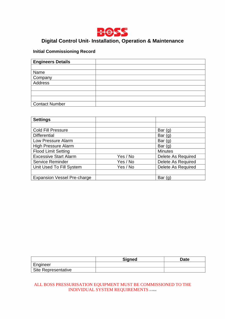
Initial Commissioning Record Engineers Details Name Company Address Contact Number Settings Cold Fill Pressure Bar (g) Differential Bar (g) Low Pressure Alarm Bar (g) High Pressure Alarm Bar (g) Flood Limit Setting Minutes Excessive Start Alarm Yes / No Delete As Required Service Reminder Yes / No Delete As Required Unit Used To Fill System Yes / No Delete As Required Expansion Vessel Pre-charge Bar (g) Signed Date Engineer Site Representative