Embed Size (px)
Citation preview
Digital Enterprise Technology Studies (CATIA and DELMIA) of the Saarinen Arch
Lawrence Wolf, Joseph Huddleston, John Schleicher, Satish Palshikar Oregon Institute of Technology, Freightliner Corporation,
Precision Castparts Corporation, Cascade Microtech Corporation [email protected], [email protected]
[email protected], [email protected]
For their studio projects while learning DET, undergraduate and graduate students modeled the St. Louis Arch using the exact mathematical relationships of Eero Saarinen. They used that digital model to do finite element stress analyses for stresses, deflections, and vibrations. They investigated the challenging construction methodology used in building the Arch. They confirmed Saarinen’s uniform stress assumptions using computing power that he never dreamed of. They checked out what was needed in the way of hydraulic force and piston travel to expand the two legs for “keystone” placement. They conceived and analyzed different tool-path strategies for the possible three- and five-axis cutting of exact physical models of that arch geometry. Most recently, using DELMIA to electronically model not only the tool path but also the machine tool operation and plant layout itself, precise 1/1000-sized models of the Arch are being cut and cast in aluminum and other materials. This paper is a follow-up of the paper submitted at the 2004 DET in Seattle entitled “CATIA Studies of the St. Louis Arch by OIT Students.” As a final step, the studies are focused on a physical model to be produced with the assistance of Freightliner LLC - a DaimlerChrysler Company, and the Precision Castparts Corporation. The long-term institutional objective for the overall project was not just to have courses in DET but also to position DET centrally within the undergraduate and graduate manufacturing and mechanical curricula, and finally to use it to its full power and functionality.
1. INTRODUCTION
Two hundred years ago, Thomas Jefferson (then President of the United States of America) commissioned Lewis and Clark to conduct a 4000-mile exploration of the Western United States commencing in St Louis, Missouri, and extending to the Pacific Ocean near what is now Portland, Oregon. The famous St. Louis Gateway Arch (The Jefferson National Expansion Memorial), designed by Finnish architect Eero Saarinen, commemorates that exceedingly successful historical event.
During the past two-year Bicentennial Celebration of the Lewis and Clark Expedition, Oregon Institute of Technology students have been doing several related studio projects in the courses in which Digital Enterprise Technology is used as the primary laboratory resource tool. These studies began in courses using CATIA
2 Digital Enterprise Technology
called “Solid Modeling,” “Finite Element Analysis,” and “Numerical Control Programming,” which are upper-divisional courses in the BS degree Mechanical Engineering Technology and Manufacturing Engineering Technology programs. This past year they have been extended into post-graduate courses using DELMIA called “Automated Technology for Tool Path Generation,” and “Plant Layout for Lean and Agile Manufacturing,” which are part of a new MS degree program in Manufacturing Engineering Technology.
The Jefferson National Expansion Memorial is also known as the Gateway Arch, and as the Saarinen Arch. It was designed by Eero Saarinen who won a design competition in 1948. Construction began in 1961. The arch was completed in 1965.
Saarinen’s concept was to have a monument of elegance, grace, and beauty meeting the competition requirement of symbolizing a large gateway to the western United States. He devised a simple and structurally efficient form that was to receive the American Institute of Architects 25-Year Award in 1990.
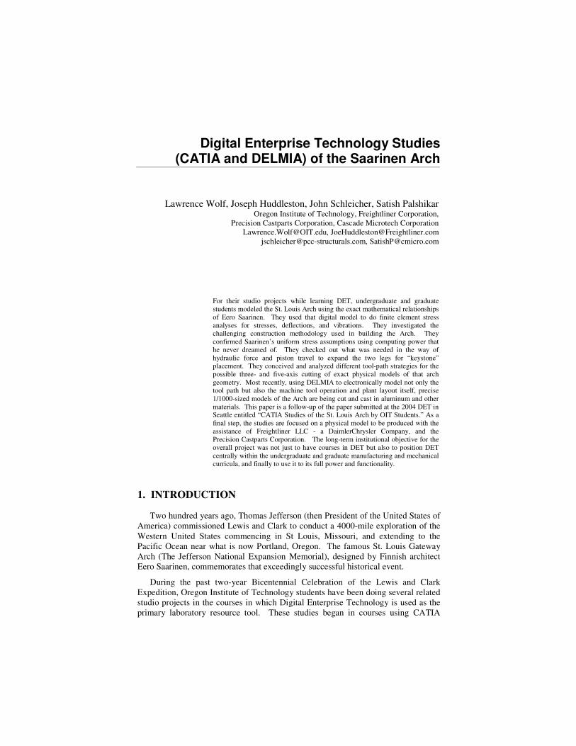
It is the tallest monument in the USA and has no straight edges (see Figure 1). It uses every ounce of material, with the exception of the internal elevators, for only one purpose. That purpose is nothing less than to defy gravity. Arguably it is the largest, if not the finest, example of “form follows function.”
Figure 1, Comparison of the Solid Model from the CATIA Screen to an Actual
Photo. The CATIA image is an infinite perspective. The photo has some distortion due to the fact that it was taken with a 100-mm lens.
The Arch is a purely mathematical shape. The centroidal curve is a catenary:
��
���
� −= 1668.99
cosh767.68x
y ft., or ��
���
� −1378.30
cosh960.20x
m.
Where x and y are the horizontal and vertical positions, respectively, of points on
the surface of the arch, and z is the distance outward from the plane of the centroidal

Digital Enterprise Technology 3
curve, the inner surfaces of the arch have the curvatures 2
2
xz
∂∂
, and 2
2
yz
∂∂
, as well as
the twist yxz
∂∂∂ 2
. A perfect subject for the study of CATIA!
The ARCH is 625 feet high by 600 feet wide at its base (190 x 183 m). The cross-section is an equilateral triangle. The side of the cross-section increases linearly with y. It is 17 feet (5.185 m) at the top of the arch and 54 feet (16.47 m) at the base.
Leave 3 lines space between the paper title and author name. Leave 5 line spaces between author affiliation and start of the abstract. Your paper should begin with a brief Introduction. 2. INTRODUCING THE STUDENTS
The students were working on the BS degree in Manufacturing or Mechanical Engineering Technology at Oregon Institute of Technology – Portland. They were third- and fourth-year students. They were employed as machinists, technicians, engineers, and managers. They were half-time students enrolled in evening courses in Solid Modeling, Finite Element Analysis, and Numerical Control Programming.
A studio approach was used emphasizing creativity. Each student had a door key and a password. Teamwork was encouraged. Mathematical theory was included along with demonstrations in CATIA. Students learned most actual CATIA from the program documentation, the textbook, and each other. While in the courses, they also did other “studios” in addition to the Arch. 3. FINITE ELEMENT ANALYSIS A homogeneous solid structure was modeled rather than a stainless shell over concrete and a carbon steel undershell. This was a “first order” analysis. An effective density was used, which is the actual weight of steel plus the weight of concrete divided by the computed volume (44.9 pounds per cubic foot or 719.3 kg per cubic meter). An effective modulus of elasticity was computed at the 300-foot-level (91.5 m) cross-section and was then used for the entire structure. The relationship for the effective modulus of elasticity is:
AEAEA
E sscceffective
+= = 2.63 E6 pounds per square inch (18.12 E9 Pa)
where: =cA the area of the concrete,
=sA the area of the steel,
=cE the elastic modulus of concrete, and
=sE the elastic modulus of steel.
4 Digital Enterprise Technology
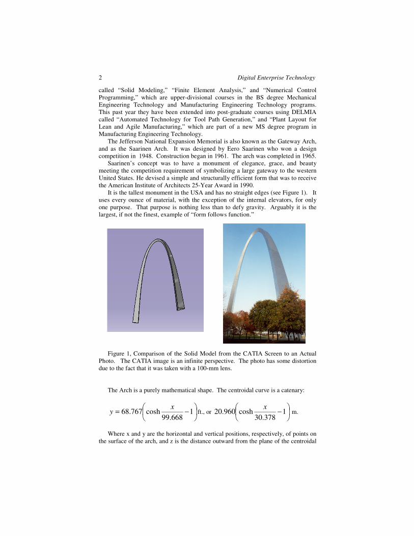
3.1. Principal Stresses from FEA The finite element analysis shows that Saarinen was correct (see Figure 2). The dominant principal stresses are all compressive and for the most part constant (ranging from about 60 to 80 psi., or 0.413 to .551 MPa). They are essentially in the direction of the centroidal curve. The exception is on the inside corner near the base, due to Saarinen’s probably not having considering the effect of the built-in condition at the base. .
Figure 2, The Principal Stresses Due to the Arch’s Own Distributed Weight. The deformation is displayed with a high magnification factor that exaggerates the
inward bending halfway up the Arch legs.
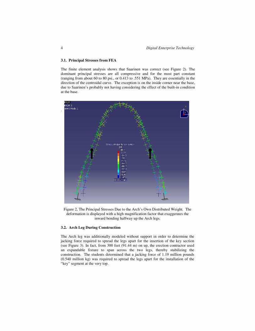
3.2. Arch Leg During Construction The Arch leg was additionally modeled without support in order to determine the jacking force required to spread the legs apart for the insertion of the key section (see Figure 3). In fact, from 300 feet (91.44 m) on up, the erection contractor used an expandable fixture to span across the two legs, thereby stabilizing the construction. The students determined that a jacking force of 1.19 million pounds (0.540 million kg) was required to spread the legs apart for the installation of the “key” segment at the very top.
Digital Enterprise Technology 5
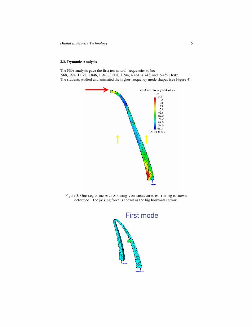
3.3. Dynamic Analysis The FEA analysis gave the first ten natural frequencies to be: .568, .924, 1.072, 1.846, 1.943, 3.808, 3.244, 4.461, 4.742, and 6.459 Hertz. The students studied and animated the higher-frequency mode shapes (see Figure 4).
Figure 3, One Leg of the Arch Showing Von Mises Stresses. The leg is shown deformed. The jacking force is shown as the big horizontal arrow.
First mode
6 Digital Enterprise Technology
Figure 4, The Arch in the First Mode of Vibration. The first mode (.568 Hertz) is a cantilever vibration straight out in the z direction.
4 MACHINING THE MODEL
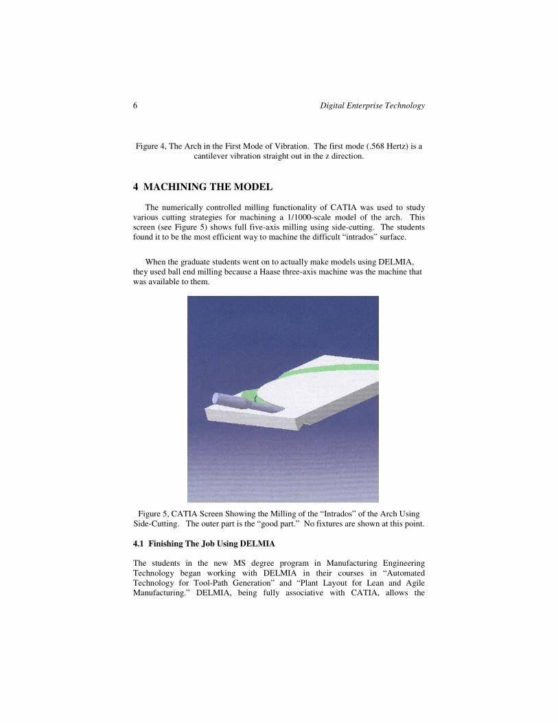
The numerically controlled milling functionality of CATIA was used to study various cutting strategies for machining a 1/1000-scale model of the arch. This screen (see Figure 5) shows full five-axis milling using side-cutting. The students found it to be the most efficient way to machine the difficult “intrados” surface.
When the graduate students went on to actually make models using DELMIA, they used ball end milling because a Haase three-axis machine was the machine that was available to them.
Figure 5, CATIA Screen Showing the Milling of the “Intrados” of the Arch Using Side-Cutting. The outer part is the “good part.” No fixtures are shown at this point. 4.1 Finishing The Job Using DELMIA The students in the new MS degree program in Manufacturing Engineering Technology began working with DELMIA in their courses in “Automated Technology for Tool-Path Generation” and “Plant Layout for Lean and Agile Manufacturing.” DELMIA, being fully associative with CATIA, allows the
Digital Enterprise Technology 7
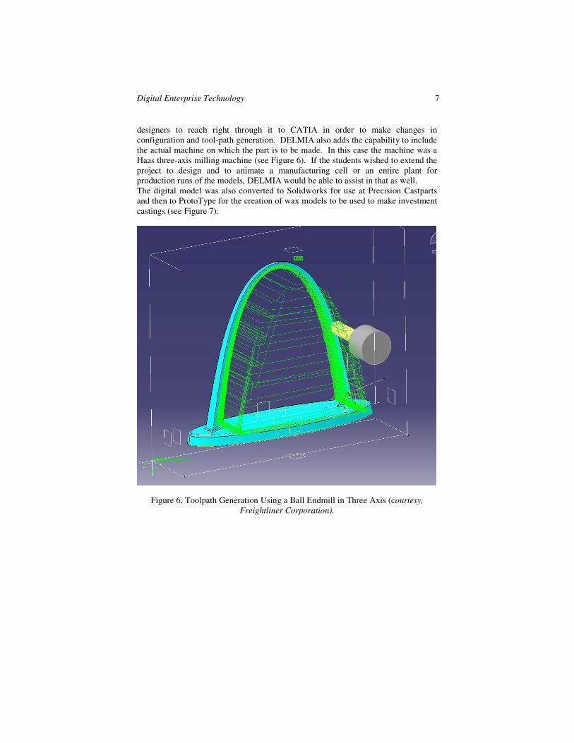
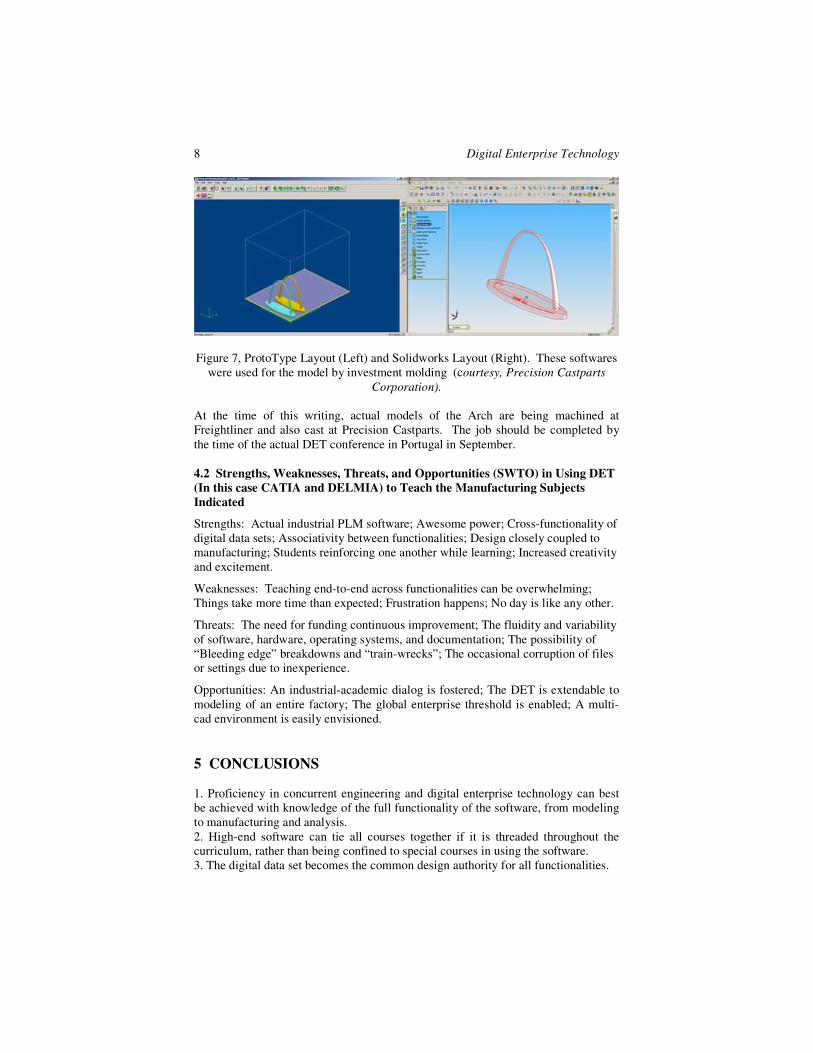
designers to reach right through it to CATIA in order to make changes in configuration and tool-path generation. DELMIA also adds the capability to include the actual machine on which the part is to be made. In this case the machine was a Haas three-axis milling machine (see Figure 6). If the students wished to extend the project to design and to animate a manufacturing cell or an entire plant for production runs of the models, DELMIA would be able to assist in that as well. The digital model was also converted to Solidworks for use at Precision Castparts and then to ProtoType for the creation of wax models to be used to make investment castings (see Figure 7).
Figure 6, Toolpath Generation Using a Ball Endmill in Three Axis (courtesy, Freightliner Corporation).
8 Digital Enterprise Technology
Figure 7, ProtoType Layout (Left) and Solidworks Layout (Right). These softwares were used for the model by investment molding (courtesy, Precision Castparts
Corporation). At the time of this writing, actual models of the Arch are being machined at Freightliner and also cast at Precision Castparts. The job should be completed by the time of the actual DET conference in Portugal in September. 4.2 Strengths, Weaknesses, Threats, and Opportunities (SWTO) in Using DET (In this case CATIA and DELMIA) to Teach the Manufacturing Subjects Indicated
Strengths: Actual industrial PLM software; Awesome power; Cross-functionality of digital data sets; Associativity between functionalities; Design closely coupled to manufacturing; Students reinforcing one another while learning; Increased creativity and excitement.
Weaknesses: Teaching end-to-end across functionalities can be overwhelming; Things take more time than expected; Frustration happens; No day is like any other.
Threats: The need for funding continuous improvement; The fluidity and variability of software, hardware, operating systems, and documentation; The possibility of “Bleeding edge” breakdowns and “train-wrecks”; The occasional corruption of files or settings due to inexperience.
Opportunities: An industrial-academic dialog is fostered; The DET is extendable to modeling of an entire factory; The global enterprise threshold is enabled; A multi-cad environment is easily envisioned. 5 CONCLUSIONS 1. Proficiency in concurrent engineering and digital enterprise technology can best be achieved with knowledge of the full functionality of the software, from modeling to manufacturing and analysis. 2. High-end software can tie all courses together if it is threaded throughout the curriculum, rather than being confined to special courses in using the software. 3. The digital data set becomes the common design authority for all functionalities.
Digital Enterprise Technology 9
4. Working in groups, in a studio fashion, is a catalyst for learning.
6 ACKNOWLEDGEMENTS Students Whose Work Appears In This Presentation: John Schleicher, development engineer “Bo” Nonn, self-employed designer-inventor Curt Kemper, manufacturing manager Ryan Patterson, designer Brian Fullbright, manufacturing engineer The co-authors of this paper were also students in the MS degree program while this work was being produced. Cooperating Corporations Freightliner LLC - - a DaimlerChrysler Company, Portland, Oregon, for donating the time on the Haas machine. Precision Castparts Corporation, Portland, Oregon, for casting the model for investment molding.