Embed Size (px)
Citation preview
Digital Fiberoptic SensorFS-N Series
In addit ion to i ts MEGA power,
the FS-N Ser ies introduces unprecedented setup ease
with one cl ick operat ion.
NEO-MEGA
ONE CLICKPRESET DATUM
2
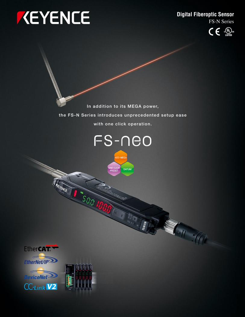
Certainty and simplicity
There are two major qualities that are important in fiber sensors.
First, the sensor must have improved basic performance, including ample beam power and accuracy,
for greater detection stability.
Second, the sensor must be easy for anyone to setup and operate.
Instant alarm readout!

3
NEO-MEGA
ONE CLICKPRESET DATUM
Complete setting in just one click
High power reduces labor hours
Automatic maintenance
ONE CLICK PRESET
NEO-MEGA
DATUM
An entirely new concept in setup ease. Just one click calibrates the sensitivity
and resets the display.
Increased sensor power greatly reduces maintenance and setup time.
The sensor automatically detects reduced light intensity due to debris build-up
and automatically re-calibrates to the original display state.
World’s most powerful beam World’s most accurate World’s highest
ambient-light resistance
NEO is supported by the world's highest level of performance
Achieves 250 times more light intensity
Detects wire as small as
ø0.6 μm (0.024 mil)
Unaffected up to
30,000 lux
Simple, Convenient
New Concept
New Concept
4
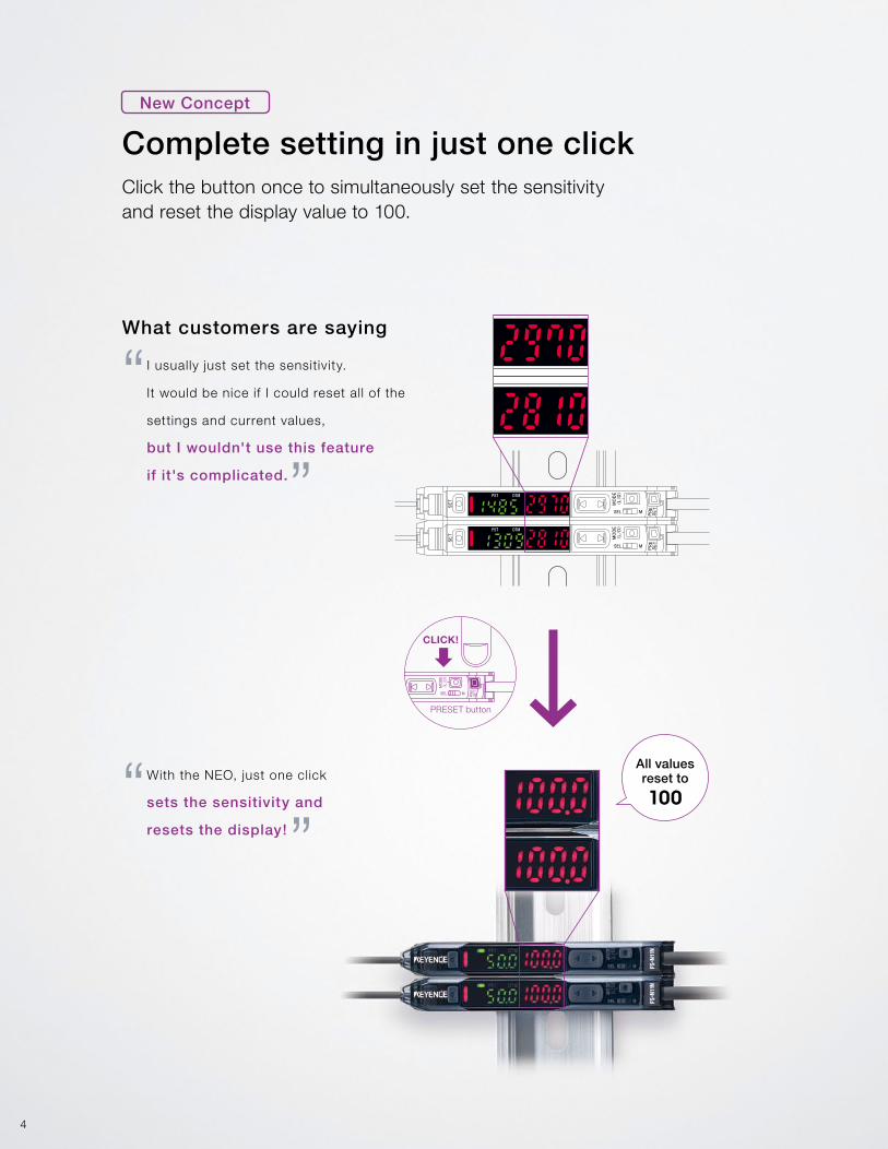
Click the button once to simultaneously set the sensitivity and reset the display value to 100.
What customers are saying
I usually just set the sensitivity.
It would be nice if I could reset all of the
settings and current values,
but I wouldn't use this feature
if it's complicated.
With the NEO, just one click
sets the sensitivity and
resets the display!
All values reset to
100
Complete setting in just one click
“
“
”
”
PRESET button
CLICK!
New Concept
5
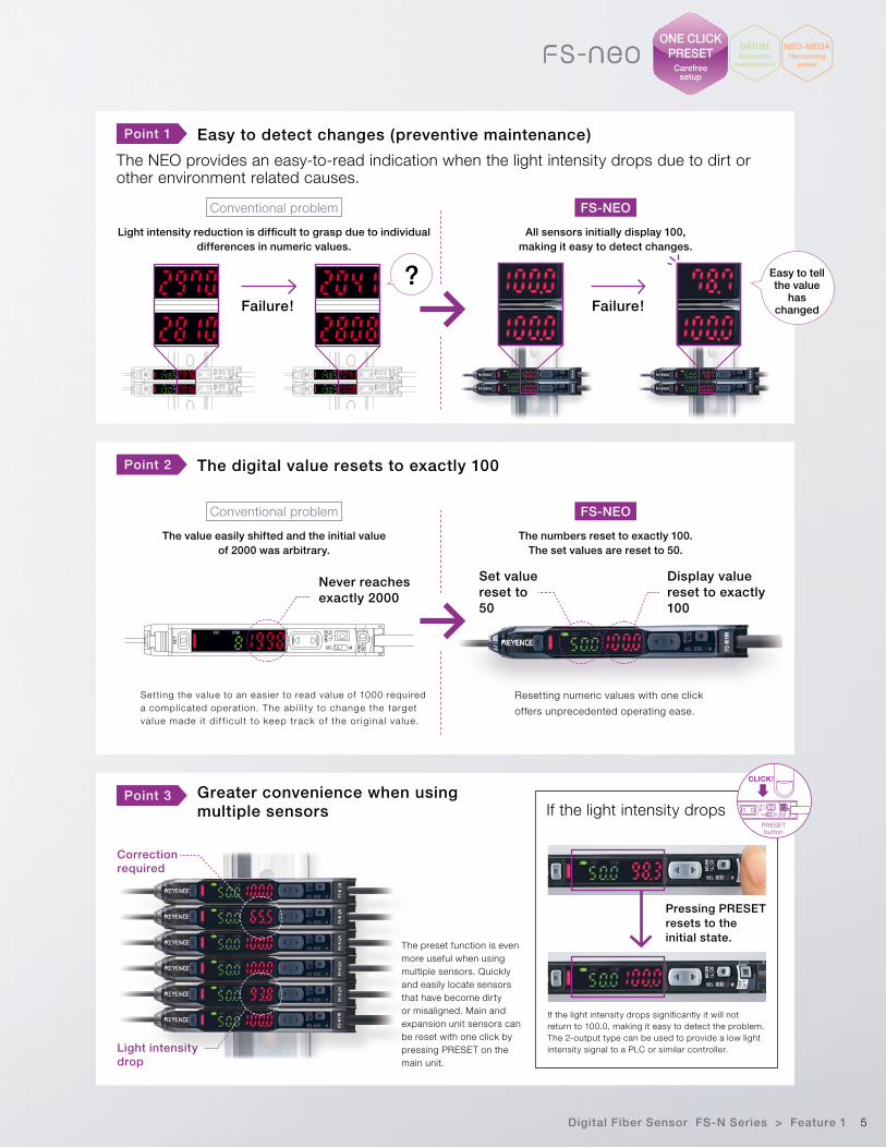
Point 1
Point 2
Point 3
Easy to detect changes (preventive maintenance)
The digital value resets to exactly 100
Greater convenience when using multiple sensors
The NEO provides an easy-to-read indication when the light intensity drops due to dirt or other environment related causes.
Conventional problem
Conventional problem
Light intensity reduction is difficult to grasp due to individual differences in numeric values.
The value easily shifted and the initial value of 2000 was arbitrary.
All sensors initially display 100, making it easy to detect changes.
The numbers reset to exactly 100. The set values are reset to 50.
Failure! Failure!
? Easy to tell the value
has changed
FS-NEO
FS-NEO
Setting the value to an easier to read value of 1000 required a complicated operation. The ab i l i t y to change the target va lue made i t d i f f icu l t to keep track of the or ig ina l va lue.
Resetting numeric values with one click
offers unprecedented operating ease.
Never reaches exactly 2000
Display value reset to exactly 100
Set value reset to 50
Correction required
Light intensity drop
The preset function is even more useful when using multiple sensors. Quickly and easily locate sensors that have become dirty or misaligned. Main and expansion unit sensors can be reset with one click by pressing PRESET on the main unit.
CLICK!
PRESET button
If the light intensity drops significantly it will not return to 100.0, making it easy to detect the problem. The 2-output type can be used to provide a low light intensity signal to a PLC or similar controller.
Pressing PRESET resets to the initial state.
If the light intensity drops
Digital Fiber Sensor FS-N Series > Feature 1
DATUMAutomatic
maintenance
NEO-MEGAHarnessing
power
ONE CLICKPRESET
Carefree setup
6 Digital Fiber Sensor FS-N Series > Feature 2
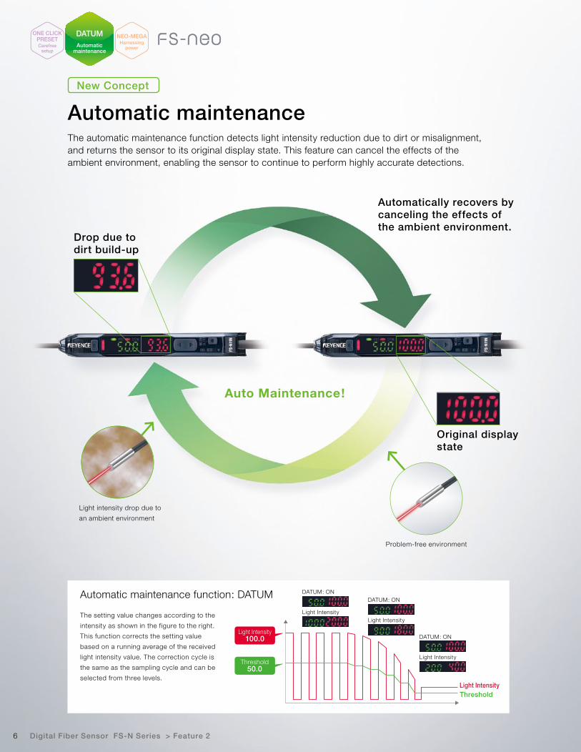
Automatically recovers by canceling the effects of the ambient environment.
Drop due to dirt build-up
Original display state
Auto Maintenance!
Light intensity drop due to
an ambient environment
Problem-free environment
The automatic maintenance function detects light intensity reduction due to dirt or misalignment, and returns the sensor to its original display state. This feature can cancel the effects of the ambient environment, enabling the sensor to continue to perform highly accurate detections.
Automatic maintenanceNew Concept
DATUMAutomatic
maintenance
ONE CLICKPRESETCarefree
setup
NEO-MEGAHarnessing
power
Automatic maintenance function: DATUM
The setting value changes according to the
intensity as shown in the figure to the right.
This function corrects the setting value
based on a running average of the received
light intensity value. The correction cycle is
the same as the sampling cycle and can be
selected from three levels.
Threshold50.0
Light Intensity100.0
Light IntensityThreshold
DATUM: ON
Light Intensity
DATUM: ON
Light Intensity
DATUM: ON
Light Intensity

7
3
1
2
Short distance [FINE]
Conventional LED
Long distance [MEGA]
NEO-LED
Power selector switch
SLIDE!
Prevent light saturation with a simple operationStrong light may result in reduced contrast. In
this case, simply press the “MODE” + “SET”
buttons to automatically adjust the NEO to the
proper light intensity.
Switch selectable MEGA powerHassle-free operation allows easy changeover
between standard and high power.
Reduced light intensity variationsWith conventional models, amplifying the projected
beam of condensed light causes the focus of the
beam to be sensitive to minute positioning errors
in the light-emitting device. The NEO-LED solves
this positioning problem by using a reflector around
the light emitting source. The reflector reduces light
intensity variations.
Circular reflector
LED chip that equally emitslight from its entire surface
The circular reflector helps compensate for light positioning errors by redirecting any stray light back into the fiber.
Detecting the seam between transparent films
Target present
Target present
No target
No target
Light saturation
Digital Fiber Sensor FS-N Series > Feature 3
"High power" = "large excess gain" that not only reduces the need for maintenance but also expands sensor head capabilities, which reduces setup time.
World’s highest power reduces maintenance time
Simple, Convenient
DATUMAutomatic
maintenance
ONE CLICKPRESETCarefree
setup
NEO-MEGAHarnessing
power
Custom LED emits concentrated intensity only from the top surface.
World's most powerful beam: NEO-MEGAGuideline for received light intensity
NEO-MEGA
Conventional standard*1
The emitted light intensity is about 4 times stronger than conventional models. *1. FS-V30 Series in FINE mode *2. FS-V30 Series
0 0501.97"
501.97"
1003.94"
1003.94"
Distance
Hys
tere
sis
Rep
eata
bili
ty
Distance
1505.91"
1505.91"
NEO-MEGA, the world's most powerful beam, allows for significant improvement of repeatability and hysteresis.
250 times greater than conventional models
FS-N SeriesConventional Model*2
Hysteresis characteristics (Typical)Repeatability (Typical)
Conventional Model*2
FS-N Series
mminch
mminch
8
Reliable even when using multiple sensors
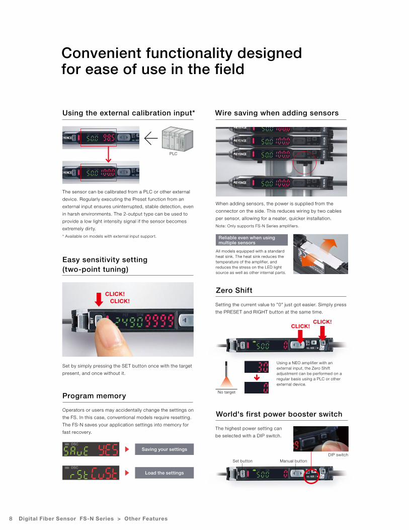
Convenient functionality designed for ease of use in the field
Using the external calibration input*
Easy sensitivity setting (two-point tuning)
Wire saving when adding sensors
PLC
The sensor can be calibrated from a PLC or other external
device. Regularly executing the Preset function from an
external input ensures uninterrupted, stable detection, even
in harsh environments. The 2-output type can be used to
provide a low light intensity signal if the sensor becomes
extremely dirty.
* Available on models with external input support.
Set by simply pressing the SET button once with the target
present, and once without it.
When adding sensors, the power is supplied from the
connector on the side. This reduces wiring by two cables
per sensor, allowing for a neater, quicker installation.
Note: Only supports FS-N Series amplifiers.
All models equipped with a standard heat sink. The heat sink reduces the temperature of the amplifier, and reduces the stress on the LED light source as well as other internal parts.
CLICK!CLICK!
Digital Fiber Sensor FS-N Series > Other Features
Zero Shift
World's first power booster switch
Program memory
Setting the current value to "0" just got easier. Simply press
the PRESET and RIGHT button at the same time.
The highest power setting can
be selected with a DIP switch.
Operators or users may accidentally change the settings on
the FS. In this case, conventional models require resetting.
The FS-N saves your application settings into memory for
fast recovery.
Using a NEO amplifier with an external input, the Zero Shift adjustment can be performed on a regular basis using a PLC or other external device.
CLICK!CLICK!
No target
Saving your settings
Load the settings
DIP switch
Set button Manual button
9
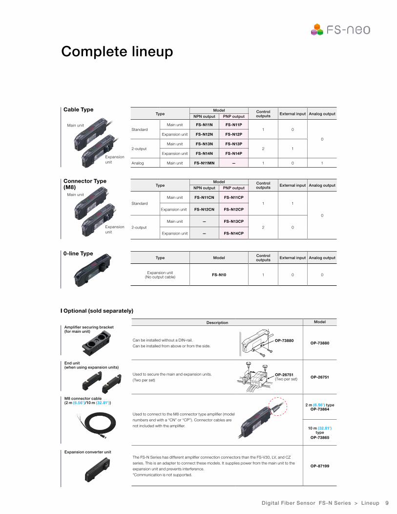
Complete lineup
Cable Type
Connector Type (M8)
0-line Type
Optional (sold separately)
Amplifier securing bracket(for main unit)
End unit(when using expansion units)
Expansion converter unit
M8 connector cable(2 m (6.56')/10 m (32.81'))
Main unit
Main unit
Expansion unit
Expansion unit
TypeModel Control
outputs External input Analog outputNPN output PNP output
StandardMain unit FS-N11N FS-N11P
1 0
0Expansion unit FS-N12N FS-N12P
2-outputMain unit FS-N13N FS-N13P
2 1Expansion unit FS-N14N FS-N14P
Analog Main unit FS-N11MN — 1 0 1
TypeModel Control
outputs External input Analog outputNPN output PNP output
Standard
Main unit FS-N11CN FS-N11CP
1 1
0
Expansion unit FS-N12CN FS-N12CP
2-output
Main unit — FS-N13CP
2 0
Expansion unit — FS-N14CP
Type Model Control outputs External input Analog output
Expansion unit(No output cable) FS-N10 1 0 0
OP-73880
OP-26751(Two per set)
Digital Fiber Sensor FS-N Series > Lineup
Description Model
Can be installed without a DIN-rail.
Can be installed from above or from the side.OP-73880
Used to secure the main and expansion units.
(Two per set)OP-26751
Used to connect to the M8 connector type amplifier (model
numbers end with a “CN” or “CP”). Connector cables are
not included with the amplifier.
2 m (6.56') typeOP-73864
10 m (32.81') type
OP-73865
The FS-N Series has different amplifier connection connectors than the FS-V30, LV, and CZ
series. This is an adapter to connect these models. It supplies power from the main unit to the
expansion unit and prevents interference.
*Communication is not supported.
OP-87199
10
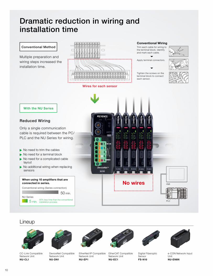
Dramatic reduction in wiring and installation time
Wires for each sensor
Conventional WiringTrim each cable for wiring to the terminal block. Identify and mark each cable.
Apply terminal connectors.
Tighten the screws on the terminal block to connect each sensor.
Reduced Wiring
Only a single communication cable is required between the PC/PLC and the NU Series for wiring.
Multiple preparation and wiring steps increased the installation time.
▲
No need to trim the cables
▲
No need for a terminal block
▲
No need for a complicated cable layout
▲
No additional wiring when replacing sensors
When using 10 amplifiers that are connected in series.
Conventional wiring (Series connection)
NU Series50 min.
5 min.90% less time than the conventional installation process
No wires
Conventional Method
With the NU Series
CC-Link Compatible Network UnitNU-CL1
DeviceNet Compatible Network UnitNU-DN1
EtherNet/IP Compatible Network UnitNU-EP1
EtherCAT Compatible Network UnitNU-EC1
Digital Fiberoptic SensorFS-N10
e-CON Network Input UnitNU-EN8N
Lineup
PLC
HMI

11
Status monitoring, settings changes, and setup backup/recovery can be done via HMI, PLC, or PC.
Improved functionality through remote access
System configuration image
It is desired to prevent false detection by the sensor before it stops production. However, there is no way to monitor it without looking at each sensor.
If multiple products are manufactured on the same line, settings need to be adjusted for each sensor during changeover.
When shipping a machine, it is necessary to provide setting procedure details for the sensors. Assembling this information can be quite time consuming.
The sensor status can be monitored on an HMI, PLC or PC, making it easier to detect problems before errors occur.
The NU allows for settings to be changed externally from an HMI, PLC or PC. As a result, changeover time can be reduced, even where sensor settings must be changed frequently.
When shipping a machine, backup settings can be quickly saved on an HMI, PLC or PC. Recovering these settings is quick and easy.
Monitoring
Tooling change (setting value change)
Settings backup/recovery
Conventional Method With the NU Series
Sensor and switch outputs can be connected with an e-CON (wire-press) connector (OP-84338 set of 2), making it possible to monitor their ON/OFF status on an HMI, PLC, or PC.
Also available: Sensor input unitNetwork Sensor Input Unit NU-EN8N Photoelectric
sensor
Data writing Data writingData reading Data reading
PLCHMI PC
Laser sensor Pressure sensor
Set screw
12
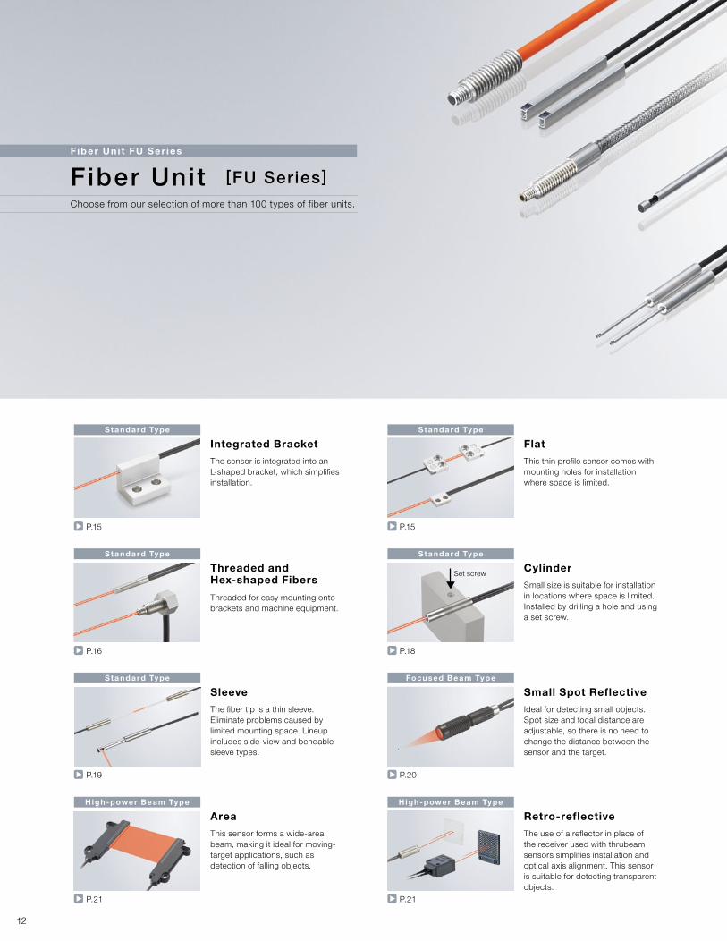
Standard Type Standard Type
Standard Type Standard Type
Standard Type Focused Beam Type
High-power Beam Type High-power Beam Type
P.15 P.15
P.16 P.18
P.19 P.20
P.21 P.21
Integrated Bracket Flat
Threaded and Hex-shaped Fibers
Cylinder
Sleeve Small Spot Reflective
Area Retro-reflective
The sensor is integrated into an L-shaped bracket, which simplifies installation.
This thin profile sensor comes with mounting holes for installation where space is limited.
Threaded for easy mounting onto brackets and machine equipment.
Small size is suitable for installation in locations where space is limited. Installed by drilling a hole and using a set screw.
The fiber tip is a thin sleeve. Eliminate problems caused by limited mounting space. Lineup includes side-view and bendable sleeve types.
Ideal for detecting small objects. Spot size and focal distance are adjustable, so there is no need to change the distance between the sensor and the target.
This sensor forms a wide-area beam, making it ideal for moving-target applications, such as detection of falling objects.
The use of a reflector in place of the receiver used with thrubeam sensors simplifies installation and optical axis alignment. This sensor is suitable for detecting transparent objects.
Fiber Uni t FU Ser ies
Fiber Unit [FU Series]
Choose from our selection of more than 100 types of fiber units.
13
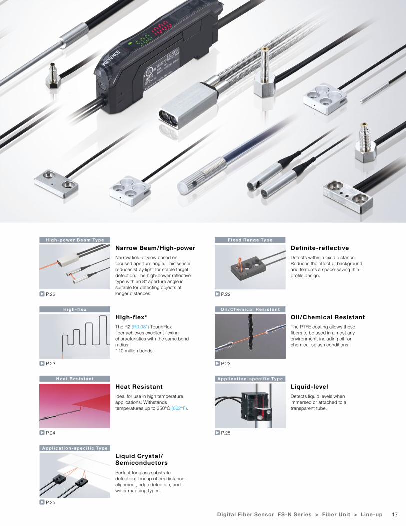
High-power Beam Type Fixed Range Type
High-f lex Oi l / Chemica l Res is tant
Heat Res is tant App l icat ion-spec i f ic Type
App l icat ion-spec i f ic Type
P.22 P.22
P.23 P.23
P.24 P.25
P.25
Narrow Beam/High-power Definite-reflective
High-flex* Oil/Chemical Resistant
Heat Resistant Liquid-level
Liquid Crystal/Semiconductors
Narrow field of view based on focused aperture angle. This sensor reduces stray light for stable target detection. The high-power reflective type with an 8° aperture angle is suitable for detecting objects at longer distances.
Detects within a fixed distance. Reduces the effect of background, and features a space-saving thin-profile design.
The R2 (R0.08") ToughFlex fiber achieves excellent flexing characteristics with the same bend radius.* 10 million bends
The PTFE coating allows these fibers to be used in almost any environment, including oil- or chemical-splash conditions.
Ideal for use in high temperature applications. Withstands temperatures up to 350°C (662°F).
Detects liquid levels when immersed or attached to a transparent tube.
Perfect for glass substrate detection. Lineup offers distance alignment, edge detection, and wafer mapping types.
Digital Fiber Sensor FS-N Series > Fiber Unit > Line-up
14
Model Page
FU- 10 P.20
FU- 11
P.21FU- 12
FU- 13
FU- 15
FU- 16
P.22FU- 16Z
FU- 18
FU- 18M P.22, 25
FU- 20 P.20
FU- 21X P.17
FU- 22X P.18, 19
FU- 23X P.18
FU- 24XP.17
FU- 25
FU- 31
P.19FU- 32
FU- 33
FU- 34
FU- 35FA
P.17
FU- 35FG
FU- 35FZ
FU- 35TG
FU- 35TZ
FU- 37P.22
FU- 38
FU- 38HP.24, 25
FU- 38K
FU- 38L P.25
FU- 38LK P.24, 25
FU- 38RP.25
FU- 38S
FU- 38V P.22, 25
FU- 4FP.18
FU- 4FZ
FU- 40P.22
FU- 40G
FU- 40S P.25
FU- 41TZP.15
FU- 42TZ
FU- 43 P.19
FU- 44TZ P.15
FU- 45XP.18, 19
FU- 46
FU- 47TZ P.15
FU- 48 P.18, 23
Model Page
FU- 48UP.23
FU- 49U
FU- 49X P.18, 23
FU- 5FP.18
FU- 5FZ
FU- 50 P.22
FU- 51TZ
P.15FU- 52TZ
FU- 53TZ
FU- 54TZ
FU- 55 P.18
FU- 56 P.18, 19
FU- 57TE P.23
FU- 57TZ P.15
FU- 58 P.18
FU- 58U P.23
FU- 59 P.18, 23
FU- 59U P.23
FU- 6F
P.17FU- 61
FU- 61Z
FU- 63
P.19FU- 63T
FU- 63Z
FU- 65X
FU- 66
P.17
FU- 66TZ
FU- 66Z
FU- 67
FU- 67G
FU- 67TG
FU- 67TZ
FU- 67V
FU- 68
P.23FU- 69U
FU- 69X
FU- 7F P.16
FU- 70U P.23
FU- 71P.16
FU- 71Z
FU- 73
P.19FU- 75F
FU- 76F
FU- 77
P.16FU- 77G
FU- 77TG
Model Page
FU- 77TZ
P.16FU- 77V
FU- 78
FU- 79P.23
FU- 79U
FU- 81C
P.24
FU- 82C
FU- 83C
FU- 84C
FU- 85A
FU- 85H
FU- 85Z
FU- 86A
FU- 86H
FU- 86Z
FU- 87
FU- 87K
FU- 88
FU- 88K
FU- 91P.23
FU- 92
FU- 93
P.25
FU- 93Z
FU- 95
FU- 95HA
FU- 95S
FU- 95W
FU- 95Z
FU- 96 P.23
FU- A05
P.21
FU- A05D
FU- A10
FU- A10D
FU- E11
FU- E40
FU- L50Z
P.15
FU- L51Z
FU- L52Z
FU- L53Z
FU- L54Z
FU- L41Z
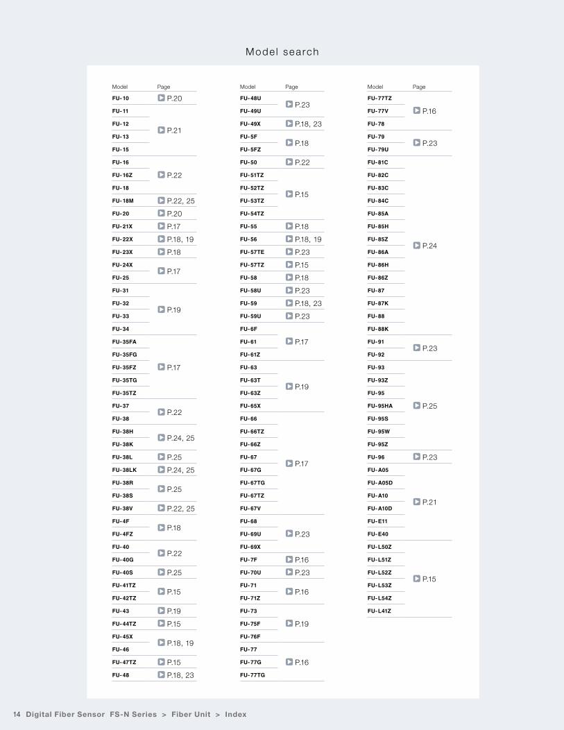
Mode l sea rch
Digital Fiber Sensor FS-N Series > Fiber Unit > Index
15Digital Fiber Sensor FS-N Series > Fiber Unit > Selection Chart
Fibre Uni t FU Ser ies
Type Fiber unit length (Diameter)Ambient temperature
Appearance(mm inch)
Minimumbend radius(mm inch)
Detecting distance (mm inch)*1 Optical axis diameter (mm inch)
(Standard target to be detected)
ModelWeightDetecting
methodBeam emitting
directionOptical axis
height (mm inch)MEGAFINE
Other power modes
Thrubeam
Top
10 0.39"
2 m 6.56' Free-cut (ø2.2 ø0.09")-40 to + 50˚C-40 to + 122˚F
R2 R0.08"ToughFlex
MEGA:FINE:
2200450
86.61"17.72"
ULTRA:SUPER:TURBO:HSP:
17001000
760290
66.93"39.37"29.92"11.42"
ø1.13 ø0.04"
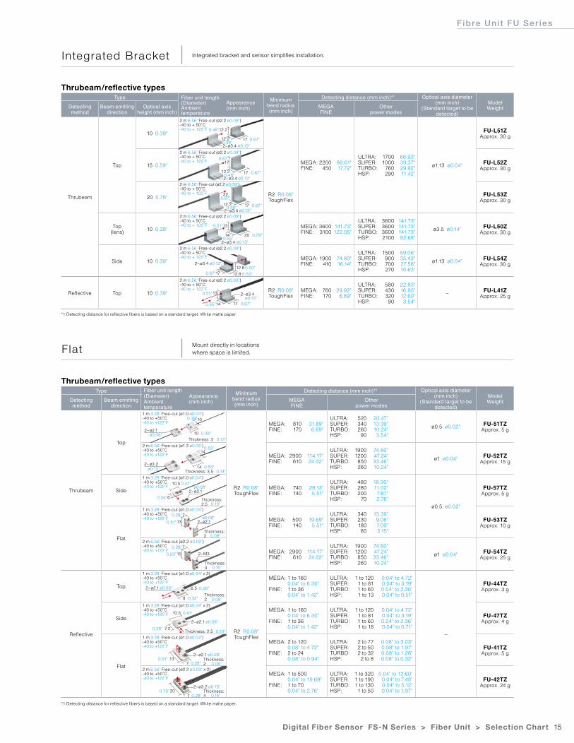
FU-L51ZApprox. 30 g
15 0.59"
2 m 6.56' Free-cut (ø2.2 ø0.09")-40 to + 50˚C-40 to + 122˚F FU-L52Z
Approx. 30 g
20 0.79"
2 m 6.56' Free-cut (ø2.2 ø0.09")-40 to + 50˚C-40 to + 122˚F FU-L53Z
Approx. 30 g
Top(lens) 10 0.39"
2 m 6.56' Free-cut (ø2.2 ø0.09")-40 to + 50˚C-40 to + 122˚F MEGA:
FINE:36003100
141.73"122.05"
ULTRA:SUPER:TURBO:HSP:
3600360036002100
141.73"141.73"141.73"82.68"
ø3.5 ø0.14" FU-L50ZApprox. 30 g
Side 10 0.39"
2 m 6.56' Free-cut (ø2.2 ø0.09")-40 to + 50˚C-40 to + 122˚F MEGA:
FINE:1900
41074.80"16.14"
ULTRA:SUPER:TURBO:HSP:
1500900700270
59.06"35.43"27.56"10.63"
ø1.13 ø0.04" FU-L54ZApprox. 30 g
Reflective Top 10 0.39"
2 m 6.56' Free-cut (ø2.2 ø0.09")-40 to + 50˚C-40 to + 122˚F R2 R0.08"
ToughFlexMEGA:FINE:
760170
29.92"6.69"
ULTRA:SUPER:TURBO:HSP:
580430320
90
22.83"16.93"12.60"3.54"
− FU-L41ZApprox. 25 g
Type Fiber unit length (Diameter)Ambient temperature
Appearance(mm inch)
Minimumbend radius(mm inch)
Detecting distance (mm inch)*1 Optical axis diameter (mm inch)
(Standard target to be detected)
ModelWeightDetecting
methodBeam emitting
directionMEGAFINE
Other power modes
Thrubeam
Top
1 m 3.28' Free-cut (ø1.0 ø0.04")-40 to +50˚C-40 to +122˚F
R2 R0.08"ToughFlex
MEGA:FINE:
810170
31.89"6.69"
ULTRA:SUPER:TURBO:HSP:
520340260
90
20.47"13.39"10.24"3.54"
ø0.5 ø0.02" FU-51TZApprox. 5 g
2 m 6.56' Free-cut (ø1.3 ø0.05")-40 to +50˚C-40 to +122˚F MEGA:
FINE:2900
610114.17"24.02"
ULTRA:SUPER:TURBO:HSP:
19001200850260
74.80"47.24"33.46"10.24"
ø1 ø0.04" FU-52TZApprox. 15 g
Side
1 m 3.28' Free-cut (ø1.0 ø0.04")-40 to +50˚C-40 to +122˚F MEGA:
FINE:740140
29.13"5.51"
ULTRA:SUPER:TURBO:HSP:
480280200
70
18.90"11.02"
7.87"2.76"
ø0.5 ø0.02"
FU-57TZApprox. 5 g
Flat
1 m 3.28' Free-cut (ø1.0 ø0.04")-40 to +50˚C-40 to +122˚F MEGA:
FINE:500140
19.69"5.51"
ULTRA:SUPER:TURBO:HSP:
34023018080
13.39"9.06"7.09"3.15"
FU-53TZApprox. 10 g
2 m 6.56' Free-cut (ø2.2 ø0.09")-40 to +50˚C-40 to +122˚F MEGA:
FINE:2900
610114.17"24.02"
ULTRA:SUPER:TURBO:HSP:
19001200850260
74.80"47.24"33.46"10.24"
ø1 ø0.04" FU-54TZApprox. 25 g
Reflective
Top
1 m 3.28' Free-cut (ø1.0 ø0.04" x 2)-40 to +50˚C-40 to +122˚F
R2 R0.08"ToughFlex
MEGA:
FINE:
1 to 1600.04" to 6.30"1 to 360.04" to 1.42"
ULTRA:SUPER:TURBO:HSP:
1 to 1201 to 811 to 601 to 13
0.04" to 4.72"0.04" to 3.19"0.04" to 2.36"0.04" to 0.51"
−
FU-44TZApprox. 3 g
Side
1 m 3.28' Free-cut (ø1.0 ø0.04" x 2)-40 to +50˚C-40 to +122˚F
MEGA:
FINE:
1 to 1600.04" to 6.30"1 to 360.04" to 1.42"
ULTRA:SUPER:TURBO:HSP:
1 to 1201 to 811 to 601 to 18
0.04" to 4.72"0.04" to 3.19"0.04" to 2.36"0.04" to 0.71"
FU-47TZApprox. 4 g
Flat
1 m 3.28' Free-cut (ø1.0 ø0.04")-40 to +50˚C-40 to +122˚F
MEGA:
FINE:
2 to 1200.08" to 4.72"2 to 240.08" to 0.94"
ULTRA:SUPER:TURBO:HSP:
2 to 772 to 502 to 32
2 to 8
0.08" to 3.03"0.08" to 1.97"0.08" to 1.26"0.08" to 0.32"
FU-41TZApprox. 5 g
2 m 6.56' Free-cut (ø2.2 ø0.09" x 2)-40 to +50˚C-40 to +122˚F
MEGA:
FINE:
1 to 5000.04" to 19.69"1 to 700.04" to 2.76"
ULTRA:SUPER:TURBO:HSP:
1 to 3201 to 1901 to 1301 to 50
0.04" to 12.60"0.04" to 7.48"0.04" to 5.12"0.04" to 1.97"
FU-42TZApprox. 24 g
Thrubeam/reflective types
Thrubeam/reflective types
Integrated Bracket Integrated bracket and sensor simplifies installation.
F lat Mount directly in locations where space is limited.
*1 Detecting distance for reflective fibers is based on a standard target: White matte paper.
*1 Detecting distance for reflective fibers is based on a standard target: White matte paper.
2−ø3.4
2−ø3.4
2−ø3.4 ø0.13"
2−ø3.4
2−ø3.4
2−ø3.4
20
17
17
17
12.8
12.8
17
14
12.2
12.2
13
17
12.2
13
17
22
14
12.20.48"
0.48"
0.48"
0.48"
0.87"
ø0.13"
0.67"
0.67"
0.67"
0.67" 0.50"0.50"
0.67"
0.67"
0.55"
0.55"
0.39"
0.39"0.12"
0.14"
0.55"
0.55"
0.41"
0.24"
0.51"
0.28"
0.28"
0.59"
0.26"
0.32"
ø0.08"
ø0.08"
ø0.08"
ø0.13"
0.79"
0.51"
0.51"
2−ø2.1
2−ø3.2
2−ø2.1
2−ø2.1 ø0.08"
2−ø2.1 ø0.08"
2−ø3.2 ø0.13"
2−ø2.1
2−ø2.1
2−M3
Thickness: 3
Thickness: 3.5
Thickness: 2
Thickness: 2.5
Thickness: 2
Thickness: 4
Thickness: 2.5
Thickness: 2
Thickness: 4
10
14
8
10.5
7
7
6
10
14
6.5
7.2
13
20
10.5
13
15
7
7
ø0.13"
ø0.13"
ø0.13"
ø0.13"
ø0.08"
0.41"
0.28"
0.51"
0.79"
0.28"
0.28"
0.10"
0.08"
0.08"
0.10"
0.08"
0.16"
0.16"
16
Type Fiber unit length (Diameter)Ambient temperature
Appearance(mm inch)
Minimumbend radius(mm inch)
Detecting distance (mm inch) Optical axis diameter (mm inch)
(Standard target to be detected)
ModelWeightDetecting
method Size/Shape MEGAFINE
Other power modes
Thrubeam
M4
Hex-shaped
2 m 6.56' Free-cut (ø2.2 ø0.09")-40 to +50˚C-40 to +122˚F R2 R0.08"
ToughFlexMEGA:FINE:
3100640
122.05"25.20"
ULTRA:SUPER:TURBO:HSP:
21001300880320
82.68"51.18"34.65"12.60"
ø1.13 ø0.04"
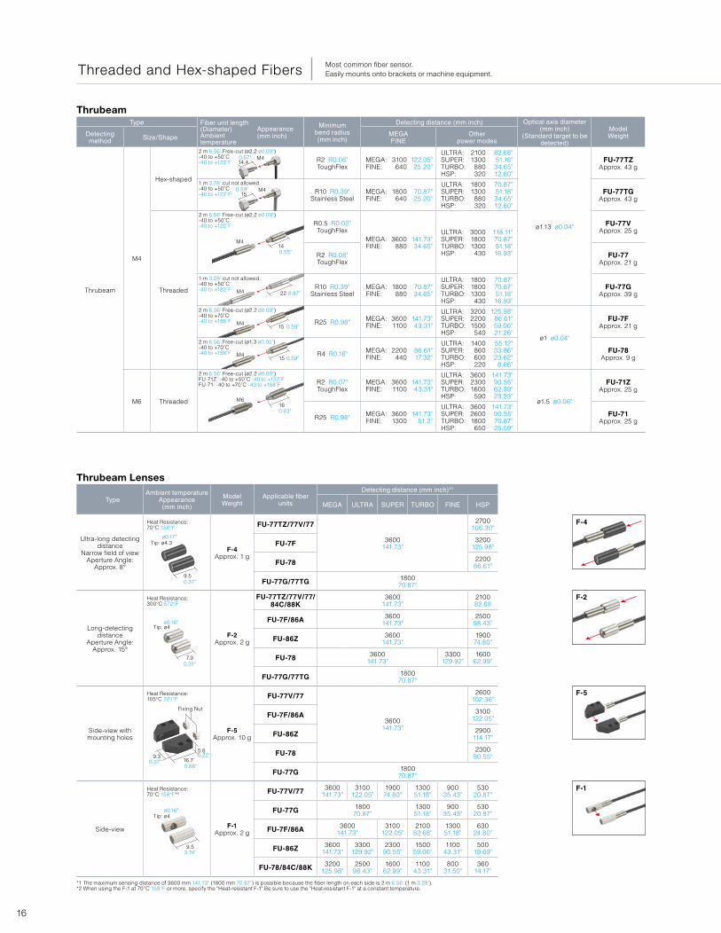
FU-77TZApprox. 43 g
1 m 3.28' cut not allowed.-40 to +50˚C-40 to +122˚F R10 R0.39"
Stainless SteelMEGA:FINE:
1800640
70.87"25.20"
ULTRA:SUPER:TURBO:HSP:
18001300880320
70.87"51.18"34.65"12.60"
FU-77TGApprox. 43 g
Threaded
2 m 6.56' Free-cut (ø2.2 ø0.09")-40 to +50˚C-40 to +122˚F R0.5 R0.02"
ToughFlexMEGA:FINE:
3600880
141.73"34.65"
ULTRA:SUPER:TURBO:HSP:
300018001300430
118.11"70.87"51.18"16.93"
FU-77VApprox. 25 g
R2 R0.08"ToughFlex
FU-77Approx. 21 g
1 m 3.28' cut not allowed.-40 to +50˚C-40 to +122˚F R10 R0.39"
Stainless SteelMEGA:FINE:
1800880
70.87"34.65"
ULTRA:SUPER:TURBO:HSP:
180018001300430
70.87"70.87"51.18"16.93"
FU-77GApprox. 39 g
2 m 6.56' Free-cut (ø2.2 ø0.09")-40 to +70˚C-40 to +158˚F R25 R0.98" MEGA:
FINE:36001100
141.73"43.31"
ULTRA:SUPER:TURBO:HSP:
320022001500540
125.98"86.61"59.06"21.26"
ø1 ø0.04"
FU-7FApprox. 21 g
2 m 6.56' Free-cut (ø1.3 ø0.05")-40 to +70˚C-40 to +158˚F R4 R0.16" MEGA:
FINE:2200
44086.61"17.32"
ULTRA:SUPER:TURBO:HSP:
1400860600220
55.12"33.86"23.62"
8.66"
FU-78Approx. 9 g
M6 Threaded
2 m 6.56' Free-cut (ø2.2 ø0.09")FU-71Z: -40 to +50˚C -40 to +122˚FFU-71: -40 to +70˚C -40 to +158˚F R2 R0.07"
ToughFlexMEGA:FINE:
36001100
141.73"43.31"
ULTRA:SUPER:TURBO:HSP:
360023001600
590
141.73"90.55"62.99"23.23"
ø1.5 ø0.06"
FU-71ZApprox. 25 g
R25 R0.98" MEGA:FINE:
36001300
141.73"51.2"
ULTRA:SUPER:TURBO:HSP:
360026001800
650
141.73"90.55"70.87"25.59"
FU-71Approx. 25 g
Thrubeam
*1 The maximum sensing distance of 3600 mm 141.73" (1800 mm 70.87") is possible because the fiber length on each side is 2 m 6.56' (1 m 3.28').*2 When using the F-1 at 70°C 158°F or more, specify the "Heat-resistant F-1".Be sure to use the "Heat-resistant F-1" at a constant temperature.
TypeAmbient temperature
Appearance (mm inch)
ModelWeight
Applicable fiber units
Detecting distance (mm inch)*1
MEGA ULTRA SUPER TURBO FINE HSP
Ultra-long detecting distance
Narrow field of viewAperture Angle:
Approx. 8°
Heat Resistance: 70°C 158°F
F-4Approx. 1 g
FU-77TZ/77V/77
3600141.73"
2700106.30"
FU-7F 3200125.98"
FU-78 220086.61"
FU-77G/77TG 180070.87"
Long-detecting distance
Aperture Angle: Approx. 15°
Heat Resistance: 300°C 572°F
F-2Approx. 2 g
FU-77TZ/77V/77/84C/88K
3600141.73"
210082.68
FU-7F/86A 3600141.73"
250098.43"
FU-86Z 3600141.73"
190074.80"
FU-78 3600141.73"
3300129.92"
160062.99"
FU-77G/77TG 180070.87"
Side-view withmounting holes
Heat Resistance: 105°C 221°F
F-5Approx. 10 g
FU-77V/77
3600141.73"
2600102.36"
FU-7F/86A 3100122.05"
FU-86Z 2900114.17"
FU-78 230090.55"
FU-77G 180070.87"
Side-view
Heat Resistance: 70°C 158°F*2
F-1Approx. 2 g
FU-77V/77 3600141.73"
3100122.05"
190074.80"
130051.18"
90035.43"
53020.87"
FU-77G 180070.87"
130051.18"
90035.43"
53020.87"
FU-7F/86A 3600141.73"
3100122.05"
210082.68"
130051.18"
63024.80"
FU-86Z 3600141.73"
3300129.92"
230090.55"
150059.06"
110043.31"
50019.69"
FU-78/84C/88K 3200125.98"
250098.43"
160062.99"
110043.31"
80031.50"
36014.17"
Thrubeam Lenses
Threaded and Hex-shaped Fibers Most common fiber sensor.Easily mounts onto brackets or machine equipment.
M4
M4
M4
M4
M4
M6
M4
14.40.57"
0.55"
0.59"
0.59"
0.87"
0.59"
0.63"
ø0.17"
ø0.16"
0.37"
0.31"
0.66"
0.22"0.37"
3.74"
ø0.16"
14
22
15
15
16
15
Tip: ø4.3
Tip: ø4
Tip: ø4
Fixing Nut
9.5
7.9
9.5
16.79.3
5.6
F-4
F-2
F-5
F-1
17Digital Fiber Sensor FS-N Series > Fiber Unit > Selection Chart
Fibre Uni t FU Ser ies
Type Fiber unit length (Diameter)Ambient temperature
Appearance(mm inch)
Minimumbend radius(mm inch)
Detecting distance (mm inch)*1
ModelWeightDetecting
method Size/Shape Detectingarrangement
MEGAFINE
Other power modes
Reflective
M3
Hex-shaped
Coaxial
1 m 3.28' Free-cut (ø1.3 ø0.05 x 2)-40 to +50˚C-40 to +122˚F
R2 R0.08"ToughFlex
MEGA:FINE:
40070
15.75"2.76"
ULTRA:SUPER:TURBO:HSP:
27017011032
10.63"6.69"4.33"1.26"
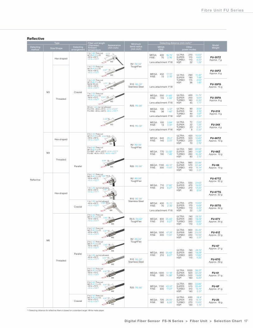
FU-35TZApprox. 7 g
Lens attachment: P.18
Threaded
1 m 3.28' Free-cut (ø1.3 ø0.05 x 2)-40 to +50˚C-40 to +122˚F
MEGA:FINE:
45072
17.72"2.76"
ULTRA:SUPER:TURBO:HSP:
29019011536
11.42"7.48"4.53"1.42"
FU-35FZApprox. 6 g
1 m 3.28' Free-cut (ø1.3 ø0.05 x 2)Spiral 30 cm-40 to +50˚C-40 to +122˚F
R10 R0.39"Stainless Steel
FU-35FGApprox. 15 gLens attachment: P.18
1 m 3.28' Free-cut (ø1.3 ø0.05 x 2)-40 to +70˚C-40 to +158˚F
R25 R0.98"
MEGA:FINE:
550110
21.65"4.33"
ULTRA:SUPER:TURBO:HSP:
40025016045
15.75"9.84"6.30"1.77"
FU-35FAApprox. 6 g
Lens attachment: P.18
50 cm 1.64' cut not allowed.FU-21X: -40 to +70˚C -40 to +158˚FFU-24X: -40 to +50°C -40 to +122˚F
MEGA:FINE:
13036
5.12"1.42"
ULTRA:SUPER:TURBO:HSP:
90544023
3.54"2.13"1.57"0.91"
FU-21XApprox. 4 g
Lens attachment: P.18
R10 R0.39"
MEGA:FINE:
10013
3.94"0.51"
ULTRA:SUPER:TURBO:HSP:
723223
8
2.83"1.26"0.91"0.32"
FU-24XApprox. 4 g
Lens attachment: P.18
M4
Hex-shaped
Parallel
2 m 6.56' Free-cut (ø1.3 ø0.05 x 2)-40 to +50˚C-40 to +122˚F
R2 R0.08"ToughFlex
MEGA:FINE:
640140
25.2"5.51"
ULTRA:SUPER:TURBO:HSP:
420320220
70
16.54"12.60"8.66"2.76"
FU-66TZApprox. 10 g
Threaded
2 m 6.56' Free-cut (ø1.3 ø0.05 x 2)FU-66Z: -40 to +50°C -40 to +122˚FFU-66: -40 to +70˚C -40 to +158˚F
MEGA:FINE:
770190
30.32"7.48"
ULTRA:SUPER:TURBO:HSP:
560380260
80
22.05"14.96"10.24"
3.15"
FU-66ZApprox. 10 g
R25 R0.98" MEGA:FINE:
1100300
43.31"11.81"
ULTRA:SUPER:TURBO:HSP:
860570410140
33.86"22.44"16.14"5.51"
FU-66Approx. 10 g
M6
Hex-shaped
2 m 6.56' Free-cut (ø2.2 ø0.09 x 2)-40 to +50˚C-40 to +122˚F
R2 R0.08"ToughFlex
MEGA:FINE:
710210
27.95"8.27"
ULTRA:SUPER:TURBO:HSP:
55047031090
21.65"18.50"12.20"3.54"
FU-67TZApprox. 32 g
1 m 3.28' cut not allowed.-40 to +50˚C-40 to +122˚F
R10 R0.39"Stainless Steel
FU-67TGApprox. 32 g
Coaxial
1 m 3.28' cut not allowed.-40 to +50˚C-40 to +122˚F
MEGA:FINE:
40070
15.75"2.76"
ULTRA:SUPER:TURBO:HSP:
27017011032
10.63"6.69"4.33"1.26"
FU-35TGApprox. 32 g
Lens attachment: P.18
Threaded
Parallel
2 m 6.56' Free-cut (ø2.2 ø0.09 x 2)-40 to +50˚C-40 to +122˚F
R0.5 R0.02"ToughFlex
MEGA:FINE:
900210
35.43"8.27"
ULTRA:SUPER:TURBO:HSP:
740490320110
29.13"19.29"12.60"4.33"
FU-67VApprox. 25 g
2 m 6.56' Free-cut (ø2.2 ø0.09 x 2)-40 to +50˚C-40 to +122˚F
R2 R0.08"ToughFlex
MEGA:FINE:
1200300
47.24"11.81"
ULTRA:SUPER:TURBO:HSP:
900590430140
35.43"23.23"16.93"
5.51"
FU-61ZApprox. 22 g
2 m 6.56' Free-cut (ø2.2 ø0.09 x 2)-40 to +50˚C-40 to +122˚F
MEGA:FINE:
900210
35.43"8.27"
ULTRA:SUPER:TURBO:HSP:
740490320110
29.13"19.29"12.60"4.33"
FU-67Approx. 21 g
1 m 3.28' cut not allowed.-40 to +50˚C-40 to +122˚F R10 R0.39"
Stainless SteelFU-67G
Approx. 29 g
2 m 6.56' Free-cut (ø2.2 ø0.09 x 2)-40 to +70˚C-40 to +158˚F
R25 R0.98"
MEGA:FINE:
1300380
51.18"14.96"
ULTRA:SUPER:TURBO:HSP:
1000820500160
39.37"32.28"19.69"6.30"
FU-61Approx. 21 g
2 m 6.56' Free-cut (ø2.2 ø0.09 x 2)-40 to +70˚C-40 to +158˚F
MEGA:FINE:
1100300
43.31"11.81"
ULTRA:SUPER:TURBO:HSP:
860570410140
33.86"22.44"16.14"5.51"
FU-6FApprox. 21 g
Coaxial
2 m 6.56' Free-cut (ø2.2 ø0.09 x 2)-40 to +70˚C-40 to +158˚F
MEGA:FINE:
720160
28.35"6.30"
ULTRA:SUPER:TURBO:HSP:
630410270130
24.8"16.14"10.63"
5.12"
FU-25Approx. 18 g
Reflective
*1 Detecting distance for reflective fibers is based on a standard target: White matte paper.
Threaded and Hex-shaped Fibers Most common fiber sensor.Easily mounts onto brackets or machine equipment.
M3
M3
M3
M3
M4
M4
M6
M6
M6
M6
M6
M6
M6
M6
M6
M6
M3
18.50.73"
0.67"
0.71"
0.91"
0.59"
0.53"
0.59"
0.62"
0.67"
0.89"
0.63"
0.63"
0.67"
0.67"
0.67"
0.67"
0.67"
17
18
15
15
13.5
15.8
17
16
16
17
17
17
17
17
22.5
23
18
Type Fiber unit length (Diameter)Ambient temperature
Appearance(mm inch)
Minimumbend radius(mm inch)
Detecting distance (mm inch)*1 Optical axis diameter (mm inch)
(Standard target to be detected)
ModelWeightDetecting
methodSize
(mm inch)MEGAFINE
Other power modes
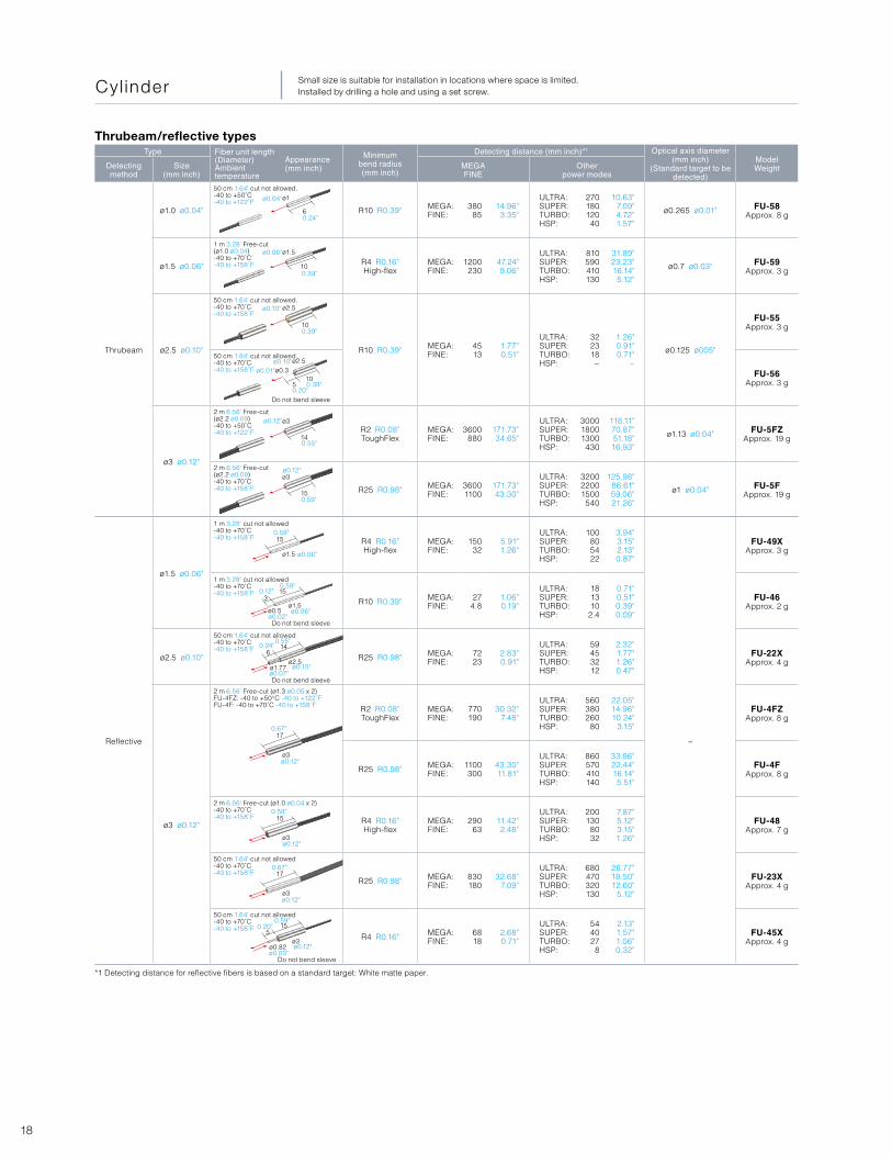
Thrubeam
ø1.0 ø0.04"
50 cm 1.64' cut not allowed.-40 to +50˚C-40 to +122˚F
R10 R0.39" MEGA:FINE:
38085
14.96"3.35"
ULTRA:SUPER:TURBO:HSP:
27018012040
10.63"7.09"4.72"1.57"
ø0.265 ø0.01" FU-58Approx. 8 g
ø1.5 ø0.06"
1 m 3.28' Free-cut (ø1.0 ø0.04)-40 to +70˚C-40 to +158˚F R4 R0.16"
High-flexMEGA:FINE:
1200230
47.24"9.06"
ULTRA:SUPER:TURBO:HSP:
810590410130
31.89"23.23"16.14"5.12"
ø0.7 ø0.03" FU-59Approx. 3 g
ø2.5 ø0.10"
50 cm 1.64' cut not allowed.-40 to +70˚C-40 to +158˚F
R10 R0.39" MEGA:FINE:
4513
1.77"0.51"
ULTRA:SUPER:TURBO:HSP:
322318−
1.26"0.91"0.71"
−
ø0.125 ø005"
FU-55Approx. 3 g
50 cm 1.64' cut not allowed.-40 to +70˚C-40 to +158˚F FU-56
Approx. 3 g
ø3 ø0.12"
2 m 6.56' Free-cut (ø2.2 ø0.09)-40 to +50˚C-40 to +122˚F R2 R0.08"
ToughFlexMEGA:FINE:
3600880
171.73"34.65"
ULTRA:SUPER:TURBO:HSP:
300018001300430
118.11"70.87"51.18"16.93"
ø1.13 ø0.04" FU-5FZApprox. 19 g
2 m 6.56' Free-cut (ø2.2 ø0.09)-40 to +70˚C-40 to +158˚F R25 R0.98" MEGA:
FINE:36001100
171.73"43.30"
ULTRA:SUPER:TURBO:HSP:
320022001500540
125.98"86.61"59.06"21.26"
ø1 ø0.04" FU-5FApprox. 19 g
Reflective
ø1.5 ø0.06"
1 m 3.28' cut not allowed-40 to +70˚C-40 to +158˚F R4 R0.16"
High-flexMEGA:FINE:
15032
5.91"1.26"
ULTRA:SUPER:TURBO:HSP:
100805422
3.94"3.15"2.13"0.87"
−
FU-49XApprox. 3 g
1 m 3.28' cut not allowed-40 to +70˚C-40 to +158˚F
R10 R0.39" MEGA:FINE:
274.8
1.06"0.19"
ULTRA:SUPER:TURBO:HSP:
181310
2.4
0.71"0.51"0.39"0.09"
FU-46Approx. 2 g
ø2.5 ø0.10"
50 cm 1.64' cut not allowed-40 to +70˚C-40 to +158˚F
R25 R0.98" MEGA:FINE:
7223
2.83"0.91"
ULTRA:SUPER:TURBO:HSP:
59453212
2.32"1.77"1.26"0.47"
FU-22XApprox. 4 g
ø3 ø0.12"
2 m 6.56' Free-cut (ø1.3 ø0.05 x 2)FU-4FZ: -40 to +50°C -40 to +122˚FFU-4F: -40 to +70˚C -40 to +158˚F R2 R0.08"
ToughFlexMEGA:FINE:
770190
30.32"7.48"
ULTRA:SUPER:TURBO:HSP:
560380260
80
22.05"14.96"10.24"
3.15"
FU-4FZApprox. 8 g
R25 R0.98" MEGA:FINE:
1100300
43.30"11.81"
ULTRA:SUPER:TURBO:HSP:
860570410140
33.86"22.44"16.14"5.51"
FU-4FApprox. 8 g
2 m 6.56' Free-cut (ø1.0 ø0.04 x 2)-40 to +70˚C-40 to +158˚F R4 R0.16"
High-flexMEGA:FINE:
29063
11.42"2.48"
ULTRA:SUPER:TURBO:HSP:
2001308032
7.87"5.12"3.15"1.26"
FU-48Approx. 7 g
50 cm 1.64' cut not allowed-40 to +70˚C-40 to +158˚F
R25 R0.98" MEGA:FINE:
830180
32.68"7.09"
ULTRA:SUPER:TURBO:HSP:
680470320130
26.77"18.50"12.60"
5.12"
FU-23XApprox. 4 g
50 cm 1.64' cut not allowed-40 to +70˚C-40 to +158˚F
R4 R0.16" MEGA:FINE:
6818
2.68"0.71"
ULTRA:SUPER:TURBO:HSP:
544027
8
2.13"1.57"1.06"0.32"
FU-45XApprox. 4 g
*1 Detecting distance for reflective fibers is based on a standard target: White matte paper.
Thrubeam/reflective types
Cyl inder Small size is suitable for installation in locations where space is limited.Installed by drilling a hole and using a set screw.
ø1ø0.04"
ø0.06"
ø0.10"
ø0.10"ø0.01"
ø0.12"
ø0.12"
ø0.06"
ø0.06"
ø0.10"ø0.07"
ø0.12"
ø0.12"
ø0.12"
ø0.12"ø0.03"
0.67"
0.59"
0.67"
0.59"0.20"
ø0.02"
0.24"
0.39"
0.39"
0.39"0.20"
0.55"
0.59"
0.59"
0.59"
0.55"
0.12"
0.24"
ø1.5
ø2.5
Do not bend sleeve
Do not bend sleeve
Do not bend sleeve
Do not bend sleeve
ø3
ø3
ø1.5
ø3
ø3
ø3
ø1.5
ø3
ø2.5
ø0.5
ø0.82
ø1.77
3
5
6
15
15
14
ø2.5ø0.3
6
10
10
14
15
15
17
17
15
105
19Digital Fiber Sensor FS-N Series > Fiber Unit > Selection Chart
Fibre Uni t FU Ser ies
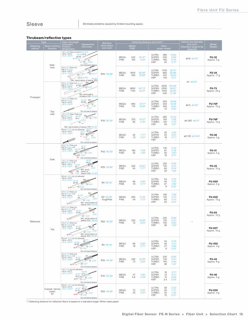
Type Fiber unit length (Diameter)Ambient temperature
Appearance(mm inch)
Minimumbend radius(mm inch)
Detecting distance (mm inch)*1 Optical axis diameter (mm inch)
(Standard target to be detected)
ModelWeightDetecting
methodBeam emitting
directionMEGAFINE
Other power modes
Thrubeam
Side-view
1 m 3.28' Free-cut (ø1.3 ø0.05")-40 to +70˚C-40 to +158˚F
R25 R0.98"
MEGA:FINE:
520100
20.47"3.94"
ULTRA:SUPER:TURBO:HSP:
38023016055
14.96"9.06"6.30"2.17"
ø0.6 ø0.02" FU-32Approx. 5 g
2 m 6.56' Free-cut (ø2.2 ø0.09")-40 to +70˚C-40 to +158˚F MEGA:
FINE:1600
33062.99"12.99"
ULTRA:SUPER:TURBO:HSP:
1100660470140
43.31"25.98"18.50"
5.51"
ø1 ø0.04"
FU-34Approx. 17 g
Topview
2 m 6.56' Free-cut (ø2.2 ø0.09")-40 to +70˚C-40 to +158˚F MEGA:
FINE:36001100
141.73"43.31"
ULTRA:SUPER:TURBO:HSP:
320022001500540
125.98"86.61"59.06"21.26"
FU-73Approx. 24 g
1 m 3.28' Free-cut (ø1.0 ø0.04")-40 to +70˚C-40 to +158˚F
R10 R0.39"
MEGA:FINE:
690170
27.17"6.69"
ULTRA:SUPER:TURBO:HSP:
500340240
72
19.69"13.39"
9.45"2.83"
ø0.5 ø0.02" FU-75FApprox. 10 g
1 m 3.28' Free- Free-cut (ø1.0 ø0.04")-40 to +70˚C-40 to +158˚F MEGA:
FINE:37085
14.57"3.35"
ULTRA:SUPER:TURBO:HSP:
26018012040
10.24"7.09"4.72"1.57"
ø0.265 ø0.01" FU-76FApprox. 10 g
50 cm 1.64' cut not allowed-40 to +70˚C-40 to +158˚F
MEGA:FINE:
4513
1.77"0.51"
ULTRA:SUPER:TURBO:HSP:
322318−
1.26"0.91"0.71"
−
ø0.125 ø0.004" FU-56Approx. 3 g
Reflective
Side
2 m 6.56' Free-cut (ø1.0 ø0.04" x 2)-40 to +70˚C-40 to +158˚F R10 R0.39" MEGA:
FINE:180
327.09"1.26"
ULTRA:SUPER:TURBO:HSP:
130815018
5.12"3.19"1.97"0.71"
−
FU-31Approx. 5 g
1 m 3.28' Free-cut (ø2.2 ø0.09" x 2)-40 to +70˚C-40 to +158˚F R25 R0.98" MEGA:
FINE:320
4512.60"
1.77"
ULTRA:SUPER:TURBO:HSP:
2501409032
9.84"5.51"3.54"1.26"
FU-33Approx. 10 g
Top
50 cm 1.64' cut not allowed-40 to +70˚C-40 to +158˚F
R4 R0.16" MEGA:FINE:
6818
2.68"0.71"
ULTRA:SUPER:TURBO:HSP:
544027
8
2.13"1.57"1.06"0.32"
FU-65XApprox. 5 g
2 m 6.56' Free-cut (ø1.3 ø0.05" x 2)-40 to +50˚C-40 to +122˚F R2 R0.08"
ToughFlexMEGA:FINE:
29054
11.42"2.13"
ULTRA:SUPER:TURBO:HSP:
1901208023
7.48"4.72"3.15"0.91"
FU-63ZApprox. 10 g
2 m 6.56' Free-cut (ø1.3 ø0.05" x 2)-40 to +70˚C-40 to +158˚F
R25 R0.98" MEGA:FINE:
33072
12.99"2.83"
ULTRA:SUPER:TURBO:HSP:
230150100
36
9.06"5.91"3.94"1.42"
FU-63Approx. 10 g
2 m 6.56' Free-cut (ø1.3 ø0.05 x 2)-40 to +70˚C-40 to +158˚F FU-63T
Approx. 10 g
50 cm 1.64' cut not allowed-40 to +70˚C-40 to +158˚F
R4 R0.16" MEGA:FINE:
6818
2.68"0.71"
ULTRA:SUPER:TURBO:HSP:
544027
8
2.13"1.57"1.06"0.32"
FU-45XApprox. 4 g
2 m 6.56' Free-cut (ø1.3 ø0.05" x 2)-40 to +70˚C-40 to +158˚F R25 R0.98" MEGA:
FINE:330
7212.99"2.83"
ULTRA:SUPER:TURBO:HSP:
230150100
36
9.06"5.91"3.94"1.42"
FU-43Approx. 8 g
1 m 3.28' cut not allowed-40 to +70˚C-40 to +158˚F
R10 R0.39" MEGA:FINE:
274.8
1.06"0.19"
ULTRA:SUPER:TURBO:HSP:
181310
2.4
0.71"0.51"0.39"0.09"
FU-46Approx. 2 g
Coaxial, narrow beam10°
50 cm 1.64' cut not allowed-40 to +70˚C-40 to +158˚F
R25 R0.98" MEGA:FINE:
7223
2.83"0.91"
ULTRA:SUPER:TURBO:HSP:
59453212
2.32"1.77"1.26"0.47"
FU-22XApprox. 4 g
*1 Detecting distance for reflective fibers is based on a standard target: White matte paper.
Thrubeam/reflective types
Sleeve Eliminate problems caused by limited mounting space.
Do not bend sleeve
Do not bend sleeve
Do not bend sleeve
Do not bend sleeve
Do not bend sleeve
Do not bend sleeve
Do not bend sleeve
Do not bend sleeve
Do not bend sleeve
Min. bend radius of sleeve: R25
Min. bend radius of sleeve: R10
Min. bend radius of sleeve: R10
Min. bend radius of sleeve: R10
Min. bend radius of sleeve: R25
Min. bend radius of sleeve: R10
Min. bend radius of sleeve: R10
ø0.82ø0.03"
ø0.12"
R0.98"
R0.98"
R0.39"
R0.39"
R0.39"
R0.39"
ø0.05"
ø0.07"
2.56"
2.64"
0.59"
0.59"
0.59"
1.77"
0.59"
ø0.03"
ø0.02"
ø0.01"
ø0.08"
ø0.08"
ø0.11"
ø0.10"
0.39"0.20"
ø0.10"
0.59"0.59"
0.59"
ø0.82
ø2.5
ø2.8
ø0.19"
M3
ø3
ø4
ø1.5
ø2.5
ø4.8
M4
M4
ø0.3
ø2
ø0.82
ø0.82
ø1.65
ø0.5
ø1.77
ø2.1
ø2
ø1.65
ø1.65
ø1.2
ø0.4
ø1.65
ø2.5
M3
ø3
ø3
15
15
5
15
15
5
22
3
6
65
67
67
67
65
45
15
15
10
15
15
15
15
15
14
15
15
15
15
15
15
15
67
M4
0.59"
0.59"
0.59"
0.59"
0.59"
0.59"
0.59"
0.59"
0.59"
0.55"
0.12"
0.20"
0.87"
0.59"
2.64"
2.64"
2.64"
0.59"
2.56"
ø0.03"
ø0.08"
ø0.07"
ø0.07"
ø0.03"
ø0.07"
ø0.02"ø0.06"
ø0.10"ø0.07"
0.24"
ø0.12"
R0.39"
20
TypeBeam spot diameter
(mm inch)Focal distance
(mm inch)Fiber unit length (Diameter)Ambient temperature
Appearance(mm inch)
ModelWeight
Minimum bend radius (mm inch)
Adjustable beam spot
ø0.9 to 3.5ø0.04" to 0.14"
10 to 300.39" to 1.18"
2 m 6.56' Free-cut(ø1.3 ø0.05 x 2)-40 to +70˚C-40 to +158˚F
FU-10Approx. 5 g R25 R0.98"
Type Beam spot diameter (mm inch)
Focal distance(mm inch)
Fiber unit length (Diameter)Ambient temperature
Appearance(mm inch)
ModelWeight
Minimum bend radius (mm inch)
Small spot Approx. ø0.1 ø0.004"
50.20"
50 cm 1.64' cut not allowed-40 to +70˚C-40 to +158˚F
FU-20Approx. 2 g R25 R0.98"
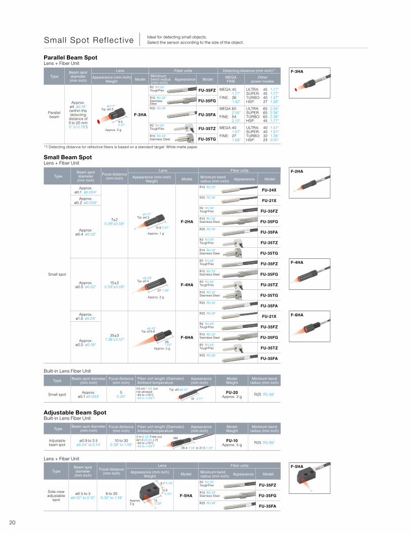
TypeBeam spot diameter
(mm inch)
Focal distance(mm inch)
Lens Fiber units
Appearance (mm inch)Weight Model Minimum bend
radius (mm inch) Appearance Model
Small spot
Approx. ø0.1 ø0.004"
7±20.28"±0.08" F-2HA
R10 R0.39"FU-24X
Approx. ø0.2 ø0.008"
R25 R0.98"FU-21X
Approx. ø0.4 ø0.02"
R2 R0.08"ToughFlex FU-35FZ
R10 R0.39"Stainless Steel FU-35FG
R25 R0.98"FU-35FA
R2 R0.08"ToughFlex FU-35TZ
R10 R0.39"Stainless Steel FU-35TG
Approx. ø0.5 ø0.02"
15±20.59"±0.08" F-4HA
R2 R0.08"ToughFlex FU-35FZ
R10 R0.39"Stainless Steel FU-35FG
R2 R0.08"ToughFlex FU-35TZ
R10 R0.39"Stainless Steel FU-35TG
R25 R0.98"FU-35FA
Approx. ø1.0 ø0.04"
35±31.38"±0.12" F-6HA
R25 R0.98"FU-21X
Approx. ø2.0 ø0.08"
R2 R0.08"ToughFlex FU-35FZ
R10 R0.39"Stainless Steel FU-35FG
R2 R0.08"ToughFlex FU-35TZ
R25 R0.98"FU-35FA
TypeBeam spot diameter
(mm inch)
Lens Fiber units Detecting distance (mm inch)*1
Appearance (mm inch)Weight Model
Minimum bend radius(mm inch)
Appearance Model MEGAFINE
Other power modes
Parallel beam
Approx. ø4 ø0.16"(within the detecting
distance of 0 to 20 mm 0" to 0.79")
F-3HA
R2 R0.08"ToughFlex FU-35FZ MEGA:
FINE:
451.77"361.42"
ULTRA:SUPER:TURBO:HSP:
45454027
1.77"1.77"1.57"1.06"
R10 R0.39"Stainless Steel
FU-35FG
R25 R0.98"
FU-35FA
MEGA:
FINE:
652.56"542.13"
ULTRA:SUPER:TURBO:HSP:
65656045
2.56"2.56"2.36"1.77"
R2 R0.08"ToughFlex FU-35TZ MEGA:
FINE:
401.57"271.06"
ULTRA:SUPER:TURBO:HSP:
40403223
1.57"1.57"1.26"0.91"
R10 R0.39"Stainless Steel FU-35TG
*1 Detecting distance for reflective fibers is based on a standard target: White matte paper.
Adjustable Beam SpotBuilt-in Lens Fiber Unit
Built-in Lens Fiber Unit
Small Beam SpotLens + Fiber Unit
Parallel Beam SpotLens + Fiber Unit
Lens + Fiber Unit
Smal l Spot Ref lect ive Ideal for detecting small objects.Select the sensor according to the size of the object.
TypeBeam spot diameter
(mm inch)
Focal distance(mm inch)
Lens Fiber units
Appearance (mm inch)Weight Model Minimum bend
radius (mm inch) Appearance Model
Side-viewadjustable
spot
ø0.5 to 3ø0.02" to 0.12"
8 to 300.32" to 1.18" F-5HA
R2 R0.08"ToughFlex FU-35FZ
R10 R0.39"Stainless Steel FU-35FG
R25 R0.98"FU-35FA
F-3HA
F-2HA
F-4HA
F-6HA
F-5HA
9.5
Tip: ø4.3
Approx. 2 g
15.6
27
26
Tip: ø4.3
Tip: ø7.4
Tip: ø10.6
Approx. 1 g
Approx. 2 g
Approx. 5 g
M6
26.4 1.04" to 31.5 1.24"
18
Tip: ø3 ø0.12"
Approx. 2 g
8.7
5.6
15
ø0.17"
ø0.17"
ø0.29"
ø0.42"
0.61"
1.06"
1.02"
0.71"
0.34"
0.22"
0.59"
0.37"
21Digital Fiber Sensor FS-N Series > Fiber Unit > Selection Chart
Fibre Uni t FU Ser ies
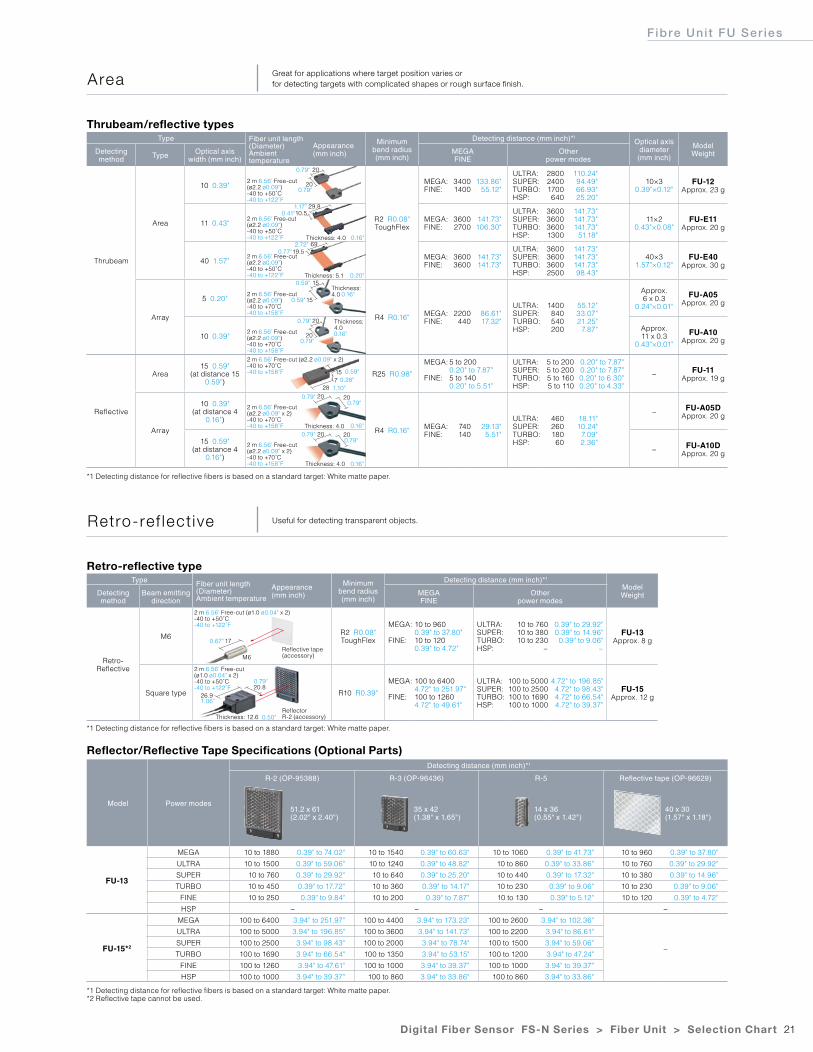
Type Fiber unit length (Diameter)Ambient temperature
Appearance(mm inch)
Minimumbend radius(mm inch)
Detecting distance (mm inch)*1Optical axis
diameter (mm inch)
ModelWeightDetecting
method Type Optical axis width (mm inch)
MEGAFINE
Other power modes
Thrubeam
Area
10 0.39"2 m 6.56' Free-cut (ø2.2 ø0.09")-40 to +50˚C-40 to +122˚F
R2 R0.08"ToughFlex
MEGA:FINE:
34001400
133.86"55.12"
ULTRA:SUPER:TURBO:HSP:
280024001700640
110.24"94.49"66.93"25.20"
10×30.39"×0.12"
FU-12Approx. 23 g
11 0.43"2 m 6.56' Free-cut (ø2.2 ø0.09")-40 to +50˚C-40 to +122˚F
MEGA:FINE:
36002700
141.73"106.30"
ULTRA:SUPER:TURBO:HSP:
3600360036001300
141.73"141.73"141.73"
51.18"
11×20.43"×0.08"
FU-E11Approx. 20 g
40 1.57"2 m 6.56' Free-cut (ø2.2 ø0.09")-40 to +50˚C-40 to +122˚F
MEGA:FINE:
36003600
141.73"141.73"
ULTRA:SUPER:TURBO:HSP:
3600360036002500
141.73"141.73"141.73"98.43"
40×31.57"×0.12"
FU-E40Approx. 30 g
Array
5 0.20"2 m 6.56' Free-cut (ø2.2 ø0.09")-40 to +70˚C-40 to +158˚F
R4 R0.16" MEGA:FINE:
2200440
86.61"17.32"
ULTRA:SUPER:TURBO:HSP:
1400840540200
55.12"33.07"21.25"
7.87"
Approx. 6 x 0.3
0.24"×0.01"
FU-A05Approx. 20 g
10 0.39"2 m 6.56' Free-cut (ø2.2 ø0.09")-40 to +70˚C-40 to +158˚F
Approx. 11 x 0.3
0.43"×0.01"
FU-A10Approx. 20 g
Reflective
Area15 0.59"
(at distance 15 0.59")
2 m 6.56' Free-cut (ø2.2 ø0.09" x 2)-40 to +70˚C-40 to +158˚F R25 R0.98"
MEGA:
FINE:
5 to 2000.20" to 7.87"5 to 1400.20" to 5.51"
ULTRA:SUPER:TURBO:HSP:
5 to 2005 to 2005 to 1605 to 110
0.20" to 7.87"0.20" to 7.87"0.20" to 6.30"0.20" to 4.33"
− FU-11Approx. 19 g
Array
10 0.39"(at distance 4
0.16")
2 m 6.56' Free-cut (ø2.2 ø0.09" x 2)-40 to +70˚C-40 to +158˚F
R4 R0.16" MEGA:FINE:
740140
29.13"5.51"
ULTRA:SUPER:TURBO:HSP:
46026018060
18.11"10.24"
7.09"2.36"
− FU-A05DApprox. 20 g
15 0.59"(at distance 4
0.16")
2 m 6.56' Free-cut (ø2.2 ø0.09" x 2)-40 to +70˚C-40 to +158˚F
− FU-A10DApprox. 20 g
Type Fiber unit length (Diameter)Ambient temperature
Appearance(mm inch)
Minimumbend radius(mm inch)
Detecting distance (mm inch)*1
ModelWeightDetecting
methodBeam emitting
directionMEGAFINE
Other power modes
Retro-Reflective
M6
2 m 6.56' Free-cut (ø1.0 ø0.04" x 2)-40 to +50˚C-40 to +122˚F
R2 R0.08"ToughFlex
MEGA:
FINE:
10 to 9600.39" to 37.80"10 to 1200.39" to 4.72"
ULTRA:SUPER:TURBO:HSP:
10 to 76010 to 38010 to 230
−
0.39" to 29.92"0.39" to 14.96"0.39" to 9.06"
−
FU-13Approx. 8 g
Square type
2 m 6.56' Free-cut (ø1.0 ø0.04" x 2)-40 to +50˚C-40 to +122˚F
R10 R0.39"
MEGA:
FINE:
100 to 64004.72" to 251.97"100 to 12604.72" to 49.61"
ULTRA:SUPER:TURBO:HSP:
100 to 5000100 to 2500100 to 1690100 to 1000
4.72" to 196.85"4.72" to 98.43"4.72" to 66.54"4.72" to 39.37"
FU-15Approx. 12 g
Model Power modes
Detecting distance (mm inch)*1
R-2 (OP-95388) R-3 (OP-96436) R-5 Reflective tape (OP-96629)
FU-13
MEGA 10 to 1880 0.39" to 74.02" 10 to 1540 0.39" to 60.63" 10 to 1060 0.39" to 41.73" 10 to 960 0.39" to 37.80"
ULTRA 10 to 1500 0.39" to 59.06" 10 to 1240 0.39" to 48.82" 10 to 860 0.39" to 33.86" 10 to 760 0.39" to 29.92"
SUPER 10 to 760 0.39" to 29.92" 10 to 640 0.39" to 25.20" 10 to 440 0.39" to 17.32" 10 to 380 0.39" to 14.96"
TURBO 10 to 450 0.39" to 17.72" 10 to 360 0.39" to 14.17" 10 to 230 0.39" to 9.06" 10 to 230 0.39" to 9.06"
FINE 10 to 250 0.39" to 9.84" 10 to 200 0.39" to 7.87" 10 to 130 0.39" to 5.12" 10 to 120 0.39" to 4.72"
HSP − − − −
FU-15*2
MEGA 100 to 6400 3.94" to 251.97" 100 to 4400 3.94" to 173.23" 100 to 2600 3.94" to 102.36"
−
ULTRA 100 to 5000 3.94" to 196.85" 100 to 3600 3.94" to 141.73" 100 to 2200 3.94" to 86.61"
SUPER 100 to 2500 3.94" to 98.43" 100 to 2000 3.94" to 78.74" 100 to 1500 3.94" to 59.06"
TURBO 100 to 1690 3.94" to 66.54" 100 to 1350 3.94" to 53.15" 100 to 1200 3.94" to 47.24"
FINE 100 to 1260 3.94" to 47.61" 100 to 1000 3.94" to 39.37" 100 to 1000 3.94" to 39.37"
HSP 100 to 1000 3.94" to 39.37" 100 to 860 3.94" to 33.86" 100 to 860 3.94" to 33.86"
*1 Detecting distance for reflective fibers is based on a standard target: White matte paper.
*1 Detecting distance for reflective fibers is based on a standard target: White matte paper.
Retro-reflective type
Thrubeam/reflective types
Reflector/Reflective Tape Specifications (Optional Parts)
*1 Detecting distance for reflective fibers is based on a standard target: White matte paper.*2 Reflective tape cannot be used.
51.2 x 61(2.02" x 2.40")
35 x 42(1.38" x 1.65")
14 x 36(0.55" x 1.42")
40 x 30(1.57" x 1.18")
Area Great for applications where target position varies or for detecting targets with complicated shapes or rough surface finish.
Retro-ref lect ive Useful for detecting transparent objects.
20
15
20
29.8
69
15
200.79"
0.16"
0.16"
0.16"
0.16"
0.16"
0.20"
1.17"
0.59"
0.59"
0.79"
0.79"
0.79"
0.67"
1.06"
0.79"
0.79"
0.79"
0.79"
0.28"1.10"
0.59"
2.72"0.77"
0.41"
0.79"
15
20
10.5
19.5
Thickness: 4.0
Thickness: 5.1
Thickness: 4.0
Thickness: 4.0
Thickness: 4.0
Thickness: 4.0
7
20
20
20
20
28
Reflective tape(accessory)
ReflectorR-2 (accessory)
M6
17
26.920.8
Thickness: 12.6 0.50"
22
Type Fiber unit length (Diameter)Ambient temperature
Appearance(mm inch)
Minimumbend radius(mm inch)
Detecting distance (mm inch)*1 Optical axis diameter (mm inch)
(Standard target to be detected)
ModelWeightDetecting
methodBeam emitting
direction Aperture angle MEGAFINE Other power modes
Thrubeam
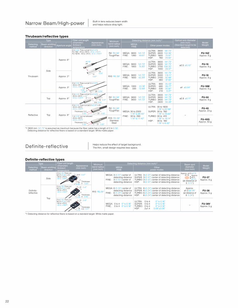
Side
Approx. 6°
2 m 6.56' Free-cut (ø1.0 ø0.04")FU-16Z: -40 to +50˚C -40 to +122˚FFU-16/18: -40 to +70˚C -40 to +158˚F R2 R0.08"
ToughFlexMEGA:FINE:
36001260
141.73"49.61"
ULTRA:SUPER:TURBO:HSP:
360026001800
760
141.73"102.36"
70.87"29.92"
ø2.5 ø0.10"
FU-16ZApprox. 8 g
R10 R0.39"
MEGA:FINE:
36001900
141.73"74.80"
ULTRA:SUPER:TURBO:HSP:
3600360027001000
141.73"141.73"106.30"
39.37"
FU-16Approx. 8 g
Approx. 2° MEGA:FINE:
36001600
141.73"62.99"
ULTRA:SUPER:TURBO:HSP:
360030002100960
141.73"118.11"92.68"37.80"
FU-18Approx. 8 g
Approx. 3°
2 m 6.56' Free-cut (ø1.0 ø0.04")-40 to +70˚C-40 to +158˚F MEGA:
FINE:1300330
51.18"12.99"
ULTRA:SUPER:TURBO:HSP:
900680530210
35.43"26.77"20.87"
8.27"
ø1 ø0.04" FU-18MApprox. 6 g
Top Approx. 6°
2 m 6.56' Free-cut (ø1.0 ø0.04")-40 to +50˚C-40 to +122˚F R2 R0.08"
ToughFlexMEGA:FINE:
36003600
141.73"141.73"
ULTRA:SUPER:TURBO:HSP:
3600360036002400
141.73"141.73"141.73"94.49"
ø2.8 ø0.11" FU-50Approx. 8 g
Reflective Top Approx. 8°
2 m 6.56' Free-cut (ø2.2 ø0.09" x 2)-40 to +50˚C-40 to +122˚F R2 R0.08"
ToughFlex MEGA:
FINE:
30 to 23001.18" to 90.55"30 to 2901.18" to 11.42"
ULTRA:
SUPER:
TURBO:
HSP:
30 to 16001.18" to 62.99"30 to 7601.18" to 29.92"30 to 4101.18" to 16.14"30 to 1601.18" to 6.30"
−
FU-40Approx. 23 g
1 m 3.28' cut not allowed-40 to +50˚C-40 to +122˚F
R10 R0.39"Stainless
Steel
FU-40GApprox. 50 g
Type Fiber unit length (Diameter)Ambient temperature
Appearance(mm inch)
Minimum bend radius(mm inch)
Detecting distance (mm inch)*1Beam spot diameter
(mm inch)
ModelWeightDetecting
methodBeam emitting
directionMEGAFINE
Other power modes
Definite-reflective
Side
2 m 6.56' Free-cut(ø1.0 ø0.04" x 2)-40 to +70˚C-40 to +158˚F
R10 R0.39"
MEGA:
FINE:
3 (0.12") center of detecting distance3 (0.12") center of detecting distance
ULTRA:SUPER:TURBO:HSP:
3 (0.12") center of detecting distance3 (0.12") center of detecting distance3 (0.12") center of detecting distance3 (0.12") center of detecting distance (at distance of
3 0.12")
FU-37Approx. 6 g
Top
2 m 6.56' Free-cut (ø1.0 ø0.04" x 2)-40 to +70˚C-40 to +158˚F
MEGA:
FINE:
6 (0.24") center of detecting distance6 (0.24") center of detecting distance
ULTRA:SUPER:TURBO:HSP:
6 (0.24") center of detecting distance6 (0.24") center of detecting distance6 (0.24") center of detecting distance6 (0.24") center of detecting distance
Approx. ø1.5 ø0.06"
(at distance of 6 0.24")
FU-38Approx. 5 g
2 m 6.56' Free-cut (ø1.0 ø0.04" x 2)-40 to +70˚C-40 to +158˚F
MEGA:FINE:
0 to 40 to 4
0" to 0.16"0" to 0.16"
ULTRA:SUPER:TURBO:HSP:
0 to 40 to 40 to 42±1.4
0" to 0.16"0" to 0.16"0" to 0.16"
0.08"±0.06"
− FU-38VApprox. 5 g
*1 3600 mm 141.73" is assumed as maximum because the fiber cable has a length of 2 m 6.56'. Detecting distance for reflective fibers is based on a standard target: White matte paper.
*1 Detecting distance for reflective fibers is based on a standard target: White matte paper.
Thrubeam/reflective types
Definite-reflective types
Narrow Beam/High-power Built-in lens reduces beam width and helps reduce stray light.
Def in i te-ref lect ive Helps reduce the effect of target background. The thin, small design requires less space.
17
13
ø4ø0.16"
0.67"
0.06"0.08" 0.79"
0.47"
0.83"
0.83"0.20"
0.20"
0.57"
0.75"
0.14"
0.16"
0.51"
20
21
21
12
1.5
Thickness: 5.2
Thickness: 5.2
4
2
3.6
Approx. ø4.5 ø0.18Approx. ø3.5ø0.14
12
12
19
19
19
Thickness: 5
Thickness: 4
Thickness: 4.3
14.4
0.75"
0.75"
0.47"
0.47"
0.20"
0.16"
0.17"
23Digital Fiber Sensor FS-N Series > Fiber Unit > Selection Chart
Fibre Uni t FU Ser ies
Type Fiber unit length (Diameter)Ambient temperature
Appearance(mm inch)
Minimum bend radius(mm inch)
Detecting distance (mm inch)*1 Optical axis diameter (mm inch)
(Standard target to be detected)
ModelWeightDetecting
methodSize
(mm inch)MEGAFINE
Other power modes
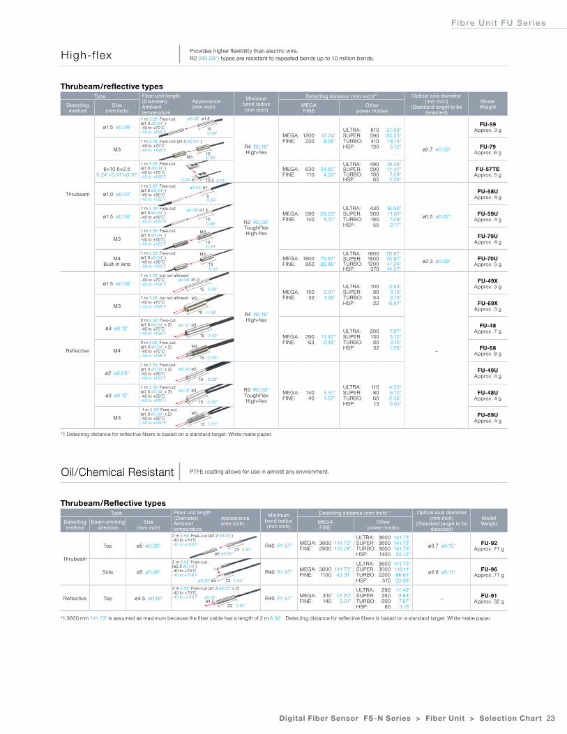
Thrubeam
ø1.5 ø0.06"
1 m 3.28' Free-cut (ø1.0 ø0.04" )-40 to +70˚C-40 to +158˚F
R4 R0.16"High-flex
MEGA:FINE:
1200230
47.24"9.06"
ULTRA:SUPER:TURBO:HSP:
810590410130
31.89"23.23"16.14"5.12" ø0.7 ø0.03"
FU-59Approx. 3 g
M3
1 m 3.28' Free-cut (ø1.0 ø0.04" )-40 to +70˚C-40 to +158˚F
FU-79Approx. 6 g
6×10.5×2.50.24"×0.41"×0.10"
1 m 3.28' Free-cut (ø1.0 ø0.04" )-40 to +70˚C-40 to +158˚F
MEGA:FINE:
630110
24.80"4.33"
ULTRA:SUPER:TURBO:HSP:
49029018065
19.29"11.42"7.09"2.56"
FU-57TEApprox. 5 g
ø1.0 ø0.04"
1 m 3.28' Free-cut (ø1.0 ø0.04" )-40 to +50˚C-40 to +122˚F
R2 R0.08"ToughFlexHigh-flex
MEGA:FINE:
590140
23.23"5.51"
ULTRA:SUPER:TURBO:HSP:
43030018055
16.93"11.81"7.09"2.17"
ø0.5 ø0.02"
FU-58UApprox. 4 g
ø1.5 ø0.06"
1 m 3.28' Free-cut (ø1.0 ø0.04" )-40 to +50˚C-40 to +122˚F
FU-59UApprox. 4 g
M3
1 m 3.28' Free-cut (ø1.0 ø0.04" )-40 to +50˚C-40 to +122˚F
FU-79UApprox. 4 g
M4Built-in lens
1 m 3.28' Free-cut (ø1.0 ø0.04" )-40 to +50˚C-40 to +122˚F
MEGA:FINE:
1800850
70.87"33.46"
ULTRA:SUPER:TURBO:HSP:
180018001200
370
70.87"70.87"47.24"14.57"
ø2.3 ø0.09" FU-70UApprox. 5 g
Reflective
ø1.5 ø0.06"
1 m 3.28' cut not allowed-40 to +70˚C-40 to +158˚F
R4 R0.16"High-flex
MEGA:FINE:
15032
5.91"1.26"
ULTRA:SUPER:TURBO:HSP:
100805422
3.94"3.15"2.13"0.87"
−
FU-49XApprox. 3 g
M3
1 m 3.28' cut not allowed-40 to +70˚C-40 to +158˚F
FU-69XApprox. 3 g
ø3 ø0.12"
2 m 6.56' Free-cut (ø1.0 ø0.04" x 2)-40 to +70˚C-40 to +158˚F
MEGA:FINE:
29063
11.42"2.48"
ULTRA:SUPER:TURBO:HSP:
2001308032
7.87"5.12"3.15"1.26"
FU-48Approx. 7 g
M4
2 m 6.56' Free-cut (ø1.0 ø0.04" x 2)-40 to +70˚C-40 to +158˚F
FU-68Approx. 8 g
ø2 ø0.08"
1 m 3.28' Free-cut (ø1.0 ø0.04" x 2)-40 to +50˚C-40 to +122˚F
R2 R0.08"ToughFlexHigh-flex
MEGA:FINE:
14040
5.51"1.57"
ULTRA:SUPER:TURBO:HSP:
110806013
4.33"5.12"2.36"0.51"
FU-49UApprox. 4 g
ø3 ø0.12"
1 m 3.28' Free-cut (ø1.0 ø0.04" x 2)-40 to +50˚C-40 to +122˚F
FU-48UApprox. 4 g
M3
1 m 3.28' Free-cut (ø1.0 ø0.04" x 2)-40 to +50˚C-40 to +122˚F
FU-69UApprox. 4 g
Type Fiber unit length (Diameter)Ambient temperature
Appearance(mm inch)
Minimum bend radius(mm inch)
Detecting distance (mm inch)*1 Optical axis diameter (mm inch)
(Standard target to be detected)
ModelWeightDetecting
methodBeam emitting
directionSize
(mm inch)MEGAFINE
Other power modes
Thrubeam
Top ø5 ø0.20"
2 m 6.56' Free-cut (ø2.2 ø0.09")-40 to +70˚C-40 to +158˚F R40 R1.57" MEGA:
FINE:36002800
141.73"110.24"
ULTRA:SUPER:TURBO:HSP:
3600360036001400
141.73"141.73"141.73"55.12"
ø3.7 ø0.15" FU-92Approx. 71 g
Side ø5 ø0.20"
2 m 6.56' Free-cut (ø2.2 ø0.09")-40 to +70˚C-40 to +158˚F
R40 R1.57" MEGA:FINE:
36001100
141.73"43.31"
ULTRA:SUPER:TURBO:HSP:
360030002200
510
141.73"118.11"86.61"20.08"
ø2.8 ø0.11" FU-96Approx. 71 g
Reflective Top ø4.5 ø0.18"
2 m 6.56' Free-cut (ø1.3 ø0.05" x 2)-40 to +70˚C-40 to +158˚F R40 R1.57" MEGA:
FINE:310140
12.20"5.51"
ULTRA:SUPER:TURBO:HSP:
290250200
80
11.42"9.84"7.87"3.15"
− FU-91Approx. 32 g
*1 Detecting distance for reflective fibers is based on a standard target: White matte paper.
*1 3600 mm 141.73" is assumed as maximum because the fiber cable has a length of 2 m 6.56'. Detecting distance for reflective fibers is based on a standard target: White matte paper.
Thrubeam/reflective types
Thrubeam/Reflective types
High-f lex Provides higher flexibility than electric wire.R2 (R0.08") types are resistant to repeated bends up to 10 million bends.
Oil/Chemical Resistant PTFE coating allows for use in almost any environment.
10
10
6
10
10
13
15
10
15
10
10
13
15
10.5
ø1.5ø0.06"
ø0.04"
ø0.06"
ø0.06"
ø0.12"
ø0.08"
ø0.12"
0.39"
0.39"
0.39"
0.39"
0.39"
0.39"
0.51"
0.39"
0.59"
0.59"
0.51"
0.59"
0.41"
0.24"
0.24"
M3
ø1
ø1.5
M3
M4
ø1.5
M3
ø3
ø2
ø3
M3
M4
6
ø5
ø4.5
ø5
22
22
23
0.87"
1.44"
0.87"
ø0.87"
ø0.20"
ø0.18"
24
Type Fiber unit length (Diameter)Ambient temperature
Appearance(mm inch)
Minimum bend radius(mm inch)
Detecting distance (mm inch)*1 Optical axis diameter (mm inch)
(Standard target to be detected)
ModelWeightDetecting
methodHeat resistant temperatures*2
MEGAFINE
Other power modes
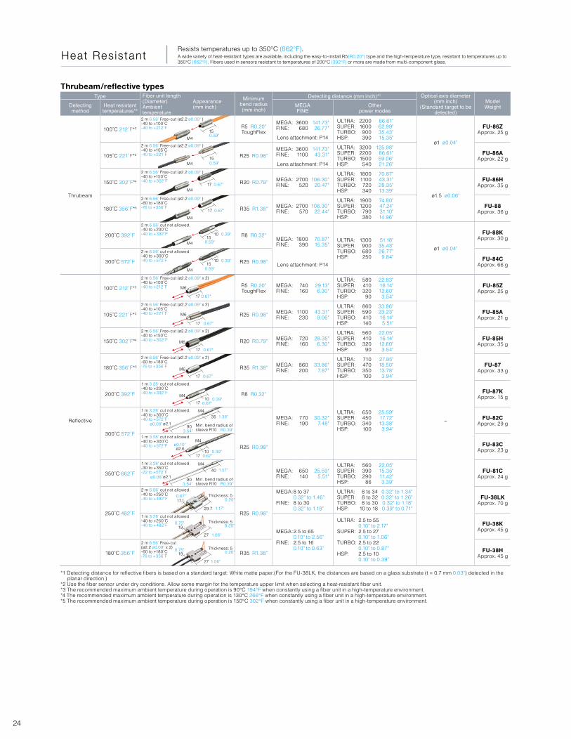
Thrubeam
100˚C 212˚F*3
2 m 6.56' Free-cut (ø2.2 ø0.09" )-40 to +100˚C-40 to +212˚F R5 R0.20"
ToughFlex
MEGA:FINE:
3600680
141.73"26.77"
ULTRA:SUPER:TURBO:HSP:
22001600900390
86.61"62.99"35.43"15.35"
ø1 ø0.04"
FU-86ZApprox. 25 g
Lens attachment: P14
105˚C 221˚F*3
2 m 6.56' Free-cut (ø2.2 ø0.09" )-40 to +105˚C-40 to +221˚F R25 R0.98"
MEGA:FINE:
36001100
141.73"43.31"
ULTRA:SUPER:TURBO:HSP:
320022001500540
125.98"86.61"59.06"21.26"
FU-86AApprox. 22 g
Lens attachment: P14
150˚C 302˚F*4
2 m 6.56' Free-cut (ø2.2 ø0.09" )-40 to +150˚C-40 to +302˚F R20 R0.79" MEGA:
FINE:2700
520106.30"
20.47"
ULTRA:SUPER:TURBO:HSP:
18001100720340
70.87"43.31"28.35"13.39"
ø1.5 ø0.06"
FU-86HApprox. 35 g
180˚C 356˚F*5
2 m 6.56' Free-cut (ø2.2 ø0.09" )-60 to +180˚C-76 to +356˚F R35 R1.38" MEGA:
FINE:2700
570106.30"
22.44"
ULTRA:SUPER:TURBO:HSP:
19001200790380
74.80"47.24"31.10"14.96"
FU-88Approx. 36 g
200˚C 392˚F
2 m 6.56' cut not allowed.-40 to +200˚C-40 to +392˚F R8 R0.32"
MEGA:FINE:
1800390
70.87"15.35"
ULTRA:SUPER:TURBO:HSP:
1300900680250
51.18"35.43"26.77"
9.84"
ø1 ø0.04"
FU-88KApprox. 30 g
300˚C 572˚F
2 m 6.56' cut not allowed.-40 to +300˚C-40 to +572˚F R25 R0.98" FU-84C
Approx. 66 gLens attachment: P14
Reflective
100˚C 212˚F*3
2 m 6.56' Free-cut (ø2.2 ø0.09" x 2)-40 to +100˚C-40 to +212˚F R5 R0.20"
ToughFlexMEGA:FINE:
740160
29.13"6.30"
ULTRA:SUPER:TURBO:HSP:
580410320
90
22.83"16.14"12.60"3.54"
−
FU-85ZApprox. 25 g
105˚C 221˚F*3
2 m 6.56' Free-cut (ø2.2 ø0.09" x 2)-40 to +105˚C-40 to +221˚F R25 R0.98" MEGA:
FINE:1100230
43.31"9.06"
ULTRA:SUPER:TURBO:HSP:
860590410140
33.86"23.23"16.14"5.51"
FU-85AApprox. 21 g
150˚C 302˚F*4
2 m 6.56' Free-cut (ø2.2 ø0.09" x 2)-40 to +150˚C-40 to +302˚F R20 R0.79" MEGA:
FINE:720160
28.35"6.30"
ULTRA:SUPER:TURBO:HSP:
560410320
90
22.05"16.14"12.60"3.54"
FU-85HApprox. 35 g
180˚C 356˚F*5
2 m 6.56' Free-cut (ø2.2 ø0.09" x 2)-60 to +180˚C-76 to +356˚F R35 R1.38" MEGA:
FINE:860200
33.86"7.87"
ULTRA:SUPER:TURBO:HSP:
710470350100
27.95"18.50"13.78"3.94"
FU-87Approx. 33 g
200˚C 392˚F
1 m 3.28' cut not allowed.-40 to +200˚C-40 to +392˚F R8 R0.32"
MEGA:FINE:
770190
30.32"7.48"
ULTRA:SUPER:TURBO:HSP:
650450340100
25.59"17.72"13.38"
3.94"
FU-87KApprox. 15 g
300˚C 572˚F
1 m 3.28' cut not allowed.-40 to +300˚C-40 to +572˚F
R25 R0.98"
FU-82CApprox. 29 g
1 m 3.28' cut not allowed.-40 to +300˚C-40 to +572˚F FU-83C
Approx. 23 g
350˚C 662˚F
1 m 3.28' cut not allowed.-30 to +350˚C-22 to +572˚F MEGA:
FINE:650140
25.59"5.51"
ULTRA:SUPER:TURBO:HSP:
560390290
86
22.05"15.35"11.42"3.39"
FU-81CApprox. 24 g
250˚C 482˚F
2 m 6.56' cut not allowed.-40 to +250˚C-40 to +482˚F
R25 R0.98"
MEGA:
FINE:
8 to 370.32" to 1.46"8 to 300.32" to 1.18"
ULTRA:SUPER:TURBO:HSP:
8 to 348 to 328 to 30
10 to 18
0.32" to 1.34"0.32" to 1.26"0.32" to 1.18"0.39" to 0.71"
FU-38LKApprox. 70 g
1 m 3.28' cut not allowed.-40 to +250˚C-40 to +482˚F
MEGA:
FINE:
2.5 to 650.10" to 2.56"2.5 to 160.10" to 0.63"
ULTRA:
SUPER:
TURBO:
HSP:
2.5 to 550.10" to 2.17"2.5 to 270.10" to 1.06"2.5 to 220.10" to 0.87"2.5 to 100.10" to 0.39"
FU-38KApprox. 45 g
180˚C 356˚F
2 m 6.56' Free-cut (ø2.2 ø0.09" x 2)-60 to +180˚C-76 to +356˚F
R35 R1.38" FU-38HApprox. 45 g
*1 Detecting distance for reflective fibers is based on a standard target: White matte paper.(For the FU-38LK, the distances are based on a glass substrate (t = 0.7 mm 0.03") detected in the planar direction.)
*2 Use the fiber sensor under dry conditions. Allow some margin for the temperature upper limit when selecting a heat-resistant fiber unit.*3 The recommended maximum ambient temperature during operation is 90°C 194°F when constantly using a fiber unit in a high-temperature environment.*4 The recommended maximum ambient temperature during operation is 130°C 266°F when constantly using a fiber unit in a high-temperature environment.*5 The recommended maximum ambient temperature during operation is 150°C 302°F when constantly using a fiber unit in a high-temperature environment.
Thrubeam/reflective types
Heat ResistantResists temperatures up to 350°C (662°F). A wide variety of heat-resistant types are available, including the easy-to-install R5(R0.20") type and the high-temperature type, resistant to temperatures up to 350°C (662°F). Fibers used in sensors resistant to temperatures of 200°C (392°F) or more are made from multi-component glass.
M4
M4
M4
M4
M4
M6
M6
M6
M6
M4
M4
ø2.6
17.1
19
19
ø2.1
ø2.1
M4
M4
Min. bend radius of sleeve R10
Min. bend radius of sleeve R10
M4
150.59"
0.59"
0.59"
0.59"
0.67"
0.67"
0.67"
0.67"
0.67"
0.67"
0.67"
0.75"
0.75"
1.17"
1.06"
1.06"
3.54"
3.54"
ø0.08"
ø0.10"
ø0.08"
0.67"
0.67"
0.39"
0.39"
0.39"
0.39"
1.57"
R0.39"
R0.39"
0.20"
0.20"
0.20"
1.38"
15
15
15
10
10
17
17
17
17
17
1710
17
29.7
27
27
10
Thickness: 5
Thickness: 5
Thickness: 5
90
90
35
40
17
25Digital Fiber Sensor FS-N Series > Fiber Unit > Selection Chart
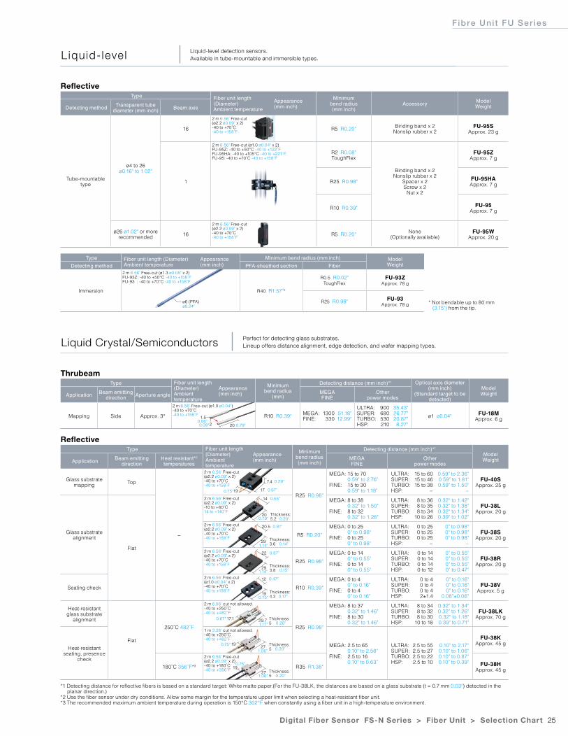
Fibre Uni t FU Ser ies
Type Fiber unit length (Diameter)Ambient temperature
Appearance(mm inch)
Minimum bend radius
(mm)
Detecting distance (mm inch)*1 Optical axis diameter(mm inch)
(Standard target to be detected)
ModelWeightApplication Beam emitting
direction Aperture angle MEGAFINE
Other power modes
Mapping Side Approx. 3°
2 m 6.56' Free-cut (ø1.0 ø0.04")-40 to +70˚C-40 to +158˚F R10 R0.39" MEGA:
FINE:1300330
51.18"12.99"
ULTRA:SUPER:TURBO:HSP:
900680530210
35.43"26.77"20.87"
8.27"
ø1 ø0.04" FU-18MApprox. 6 g
Type Fiber unit length (Diameter)Ambient temperature
Appearance(mm inch)
Minimum bend radius(mm inch)
Detecting distance (mm inch)*1
ModelWeight Application Beam emitting
directionHeat resistant*2
temperaturesMEGAFINE
Other power modes
Glass substratemapping Top
−
2 m 6.56' Free-cut (ø2.2 ø0.09" x 2)-40 to +70˚C-40 to +158˚F
R25 R0.98"
MEGA:
FINE:
15 to 700.59" to 2.76"15 to 300.59" to 1.18"
ULTRA:SUPER:TURBO:HSP:
15 to 6015 to 4615 to 38
−
0.59" to 2.36"0.59" to 1.81"0.59" to 1.50"
−
FU-40SApprox. 25 g
Glass substratealignment
Flat
2 m 6.56' Free-cut (ø2.2 ø0.09" x 2)-10 to +60˚C14 to +140˚F
MEGA:
FINE:
8 to 380.32" to 1.50"8 to 320.32" to 1.26"
ULTRA:SUPER:TURBO:HSP:
8 to 368 to 358 to 34
10 to 26
0.32" to 1.42"0.32" to 1.38"0.32" to 1.34"0.39" to 1.02"
FU-38LApprox. 20 g
2 m 6.56' Free-cut (ø2.2 ø0.09" x 2)-40 to +70˚C-40 to +158˚F
R5 R0.20"
MEGA:
FINE:
0 to 250" to 0.98"0 to 250" to 0.98"
ULTRA:SUPER:TURBO:HSP:
0 to 250 to 250 to 25
−
0" to 0.98"0" to 0.98"0" to 0.98"
−
FU-38SApprox. 20 g
2 m 6.56' Free-cut (ø2.2 ø0.09" x 2)-40 to +70˚C-40 to +158˚F
R25 R0.98"
MEGA:
FINE:
0 to 140" to 0.55"0 to 140" to 0.55"
ULTRA:SUPER:TURBO:HSP:
0 to 140 to 140 to 140 to 12
0" to 0.55"0" to 0.55"0" to 0.55"0" to 0.47"
FU-38RApprox. 20 g
Seating check
2 m 6.56' Free-cut (ø1.0 ø0.04" x 2)-40 to +70˚C-40 to +158˚F
R10 R0.39"
MEGA:
FINE:
0 to 40" to 0.16"0 to 40" to 0.16"
ULTRA:SUPER:TURBO:HSP:
0 to 40 to 40 to 42±1.4
0" to 0.16"0" to 0.16"0" to 0.16"
0.08"±0.06"
FU-38VApprox. 5 g
Heat-resistantglass substrate
alignment
Flat
250˚C 482˚F
2 m 6.56' cut not allowed.-40 to +250˚C-40 to +482˚F
R25 R0.98"
MEGA:
FINE:
8 to 370.32" to 1.46"8 to 300.32" to 1.46"
ULTRA:SUPER:TURBO:HSP:
8 to 348 to 328 to 30
10 to 18
0.32" to 1.34"0.32" to 1.26"0.32" to 1.18"0.39" to 0.71"
FU-38LKApprox. 70 g
Heat-resistantseating, presence
check
1 m 3.28' cut not allowed.-40 to +250˚C-40 to +482˚F
MEGA:
FINE:
2.5 to 650.10" to 2.56"2.5 to 160.10" to 0.63"
ULTRA:SUPER:TURBO:HSP:
2.5 to 552.5 to 272.5 to 222.5 to 10
0.10" to 2.17"0.10" to 1.06"0.10" to 0.87"0.10" to 0.39"
FU-38KApprox. 45 g
180˚C 356˚F*3
2 m 6.56' Free-cut (ø2.2 ø0.09" x 2)-40 to +180˚C-40 to +356˚F
R35 R1.38" FU-38HApprox. 45 g
Type Fiber unit length (Diameter)Ambient temperature
Appearance(mm inch)
Minimum bend radius(mm inch)
Accessory ModelWeight Detecting method Transparent tube
diameter (mm inch) Beam axis
Tube-mountable type
ø4 to 26ø0.16" to 1.02"
16
2 m 6.56' Free-cut (ø2.2 ø0.09" x 2)-40 to +70˚C-40 to +158˚F
R5 R0.20" Binding band x 2Nonslip rubber x 2
FU-95SApprox. 23 g
1
2 m 6.56' Free-cut (ø1.0 ø0.04" x 2)FU-95Z: -40 to +50°C -40 to +122˚FFU-95HA: -40 to +105°C -40 to +221˚FFU-95: -40 to +70˚C -40 to +158˚F
R2 R0.08"ToughFlex
Binding band x 2Nonslip rubber x 2
Spacer x 2Screw x 2
Nut x 2
FU-95ZApprox. 7 g
R25 R0.98" FU-95HAApprox. 7 g
R10 R0.39" FU-95Approx. 7 g
ø26 ø1.02" or morerecommended 16
2 m 6.56' Free-cut (ø2.2 ø0.09" x 2)-40 to +70˚C-40 to +158˚F
R5 R0.20" None(Optionally available)
FU-95WApprox. 20 g
Type Fiber unit length (Diameter)Ambient temperature
Appearance(mm inch)
Minimum bend radius (mm inch) ModelWeight Detecting method PFA-sheathed section Fiber
Immersion
2 m 6.56' Free-cut (ø1.3 ø0.05" x 2)FU-93Z: -40 to +50°C -40 to +158˚FFU-93 : -40 to +70°C -40 to +158˚F
R40 R1.57"*
R0.5 R0.02"ToughFlex
FU-93ZApprox. 78 g
R25 R0.98" FU-93Approx. 78 g
*1 Detecting distance for reflective fibers is based on a standard target: White matte paper.(For the FU-38LK, the distances are based on a glass substrate (t = 0.7 mm 0.03") detected in the planar direction.)
*2 Use the fiber sensor under dry conditions. Allow some margin for the temperature upper limit when selecting a heat-resistant fiber unit. *3 The recommended maximum ambient temperature during operation is 150°C 302°F when constantly using a fiber unit in a high-temperature environment.
* Not bendable up to 80 mm (3.15") from the tip.
Thrubeam
Reflective
Reflective
Liquid- leve l Liquid-level detection sensors.Available in tube-mountable and immersible types.
Liquid Crystal/Semiconductors Perfect for detecting glass substrates.Lineup offers distance alignment, edge detection, and wafer mapping types.
ø6 (PFA)ø0.24"
0.79"
0.29"
0.67"
0.55"
0.81"
0.87"
0.47"
0.79"
1.14"
1.14"
0.75"
0.67"
0.75"
0.75"
1.17"
1.06"
1.06"
0.75"
0.08"0.06"
202
1.5
17
20
19
29
29
Thickness: 5.2
Thickness: 4.3
Thickness: 3.6
Thickness: 3.8
19
7.4
14
12
20.5
22
17.1 29.7 Thickness: 5
19
19
27
27
Thickness: 5
Thickness: 5
0.20"
0.14"
0.15"
0.17"
0.20"
0.20"
0.20"
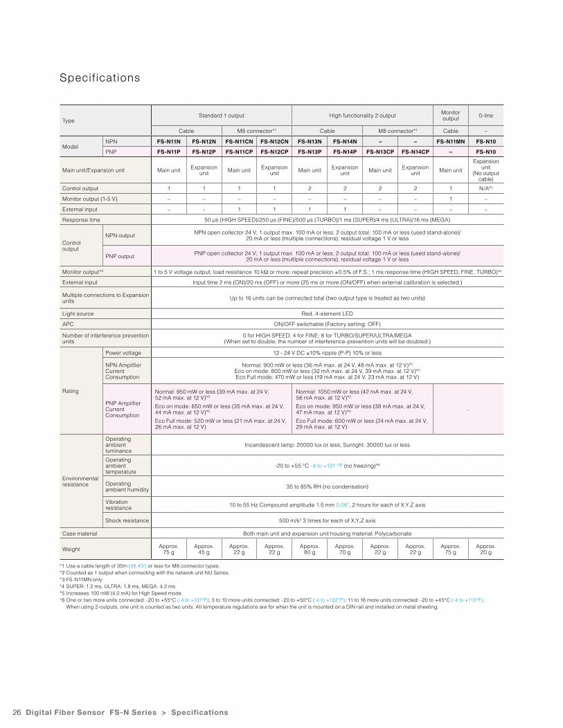
26
Speci f icat ions
Digital Fiber Sensor FS-N Series > Specifications
TypeStandard 1 output High functionality 2 output Monitor
output 0-line
Cable M8 connector*1 Cable M8 connector*1 Cable –
ModelNPN FS-N11N FS-N12N FS-N11CN FS-N12CN FS-N13N FS-N14N – – FS-N11MN FS-N10
PNP FS-N11P FS-N12P FS-N11CP FS-N12CP FS-N13P FS-N14P FS-N13CP FS-N14CP – FS-N10
Main unit/Expansion unit Main unit Expansion unit Main unit Expansion
unit Main unit Expansion unit Main unit Expansion
unit Main unit
Expansion unit
(No output cable)
Control output 1 1 1 1 2 2 2 2 1 N/A*2
Monitor output (1-5 V) – – – – – – – – 1 –
External input – – 1 1 1 1 – – – –
Response time 50 µs (HIGH SPEED)/250 µs (FINE)/500 µs (TURBO)/1 ms (SUPER)/4 ms (ULTRA)/16 ms (MEGA)
Controloutput
NPN output NPN open collector 24 V; 1 output max: 100 mA or less; 2 output total: 100 mA or less (used stand-alone)/20 mA or less (multiple connections); residual voltage 1 V or less
PNP output PNP open collector 24 V; 1 output max: 100 mA or less; 2 output total: 100 mA or less (used stand-alone)/20 mA or less (multiple connections); residual voltage 1 V or less
Monitor output*3 1 to 5 V voltage output; load resistance 10 kΩ or more; repeat precision ±0.5% of F.S.; 1 ms response time (HIGH SPEED, FINE, TURBO)*4
External input Input time 2 ms (ON)/20 ms (OFF) or more (25 ms or more (ON/OFF) when external calibration is selected.)
Multiple connections to Expansion units Up to 16 units can be connected total (two output type is treated as two units)
Light source Red, 4-element LED
APC ON/OFF switchable (Factory setting: OFF)
Number of interference prevention units
0 for HIGH SPEED; 4 for FINE; 8 for TURBO/SUPER/ULTRA/MEGA (When set to double, the number of interference-prevention units will be doubled.)
Rating
Power voltage 12 - 24 V DC ±10% ripple (P-P) 10% or less
NPN Amplifier Current Consumption
Normal: 900 mW or less (36 mA max. at 24 V, 48 mA max. at 12 V)*5
Eco on mode: 800 mW or less (32 mA max. at 24 V, 39 mA max. at 12 V)*5
Eco Full mode: 470 mW or less (19 mA max. at 24 V, 23 mA max. at 12 V)
PNP Amplifier Current Consumption
Normal: 950 mW or less (39 mA max. at 24 V, 52 mA max. at 12 V)*5
Eco on mode: 850 mW or less (35 mA max. at 24 V, 44 mA max. at 12 V)*5
Eco Full mode: 520 mW or less (21 mA max. at 24 V, 26 mA max. at 12 V)
Normal: 1050 mW or less (42 mA max. at 24 V, 56 mA max. at 12 V)*5
Eco on mode: 950 mW or less (38 mA max. at 24 V, 47 mA max. at 12 V)*5
Eco Full mode: 600 mW or less (24 mA max. at 24 V, 29 mA max. at 12 V)
–
Environmental resistance
Operating ambient luminance
Incandescent lamp: 20000 lux or less; Sunlight: 30000 lux or less
Operating ambient temperature
-20 to +55 °C -4 to +131 °F (no freezing)*6
Operating ambient humidity 35 to 85% RH (no condensation)
Vibration resistance 10 to 55 Hz Compound amplitude 1.5 mm 0.06", 2 hours for each of X,Y,Z axis
Shock resistance 500 m/s2 3 times for each of X,Y,Z axis
Case material Both main unit and expansion unit housing material: Polycarbonate
Weight Approx. 75 g
Approx. 45 g
Approx. 22 g
Approx. 22 g
Approx. 80 g
Approx. 70 g
Approx. 22 g
Approx. 22 g
Approx. 75 g
Approx. 20 g
*1 Use a cable length of 30m (98.43') or less for M8 connector types.*2 Counted as 1 output when connecting with the network unit NU Series.*3 FS-N11MN only*4 SUPER: 1.2 ms, ULTRA: 1.8 ms, MEGA: 4.2 ms*5 Increases 100 mW (4.0 mA) for High Speed mode*6 One or two more units connected: -20 to +55°C (-4 to +131°F); 3 to 10 more units connected: -20 to +50°C (-4 to +122°F); 11 to 16 more units connected: -20 to +45°C (-4 to +113°F). When using 2-outputs, one unit is counted as two units. All temperature regulations are for when the unit is mounted on a DIN rail and installed on metal sheeting.
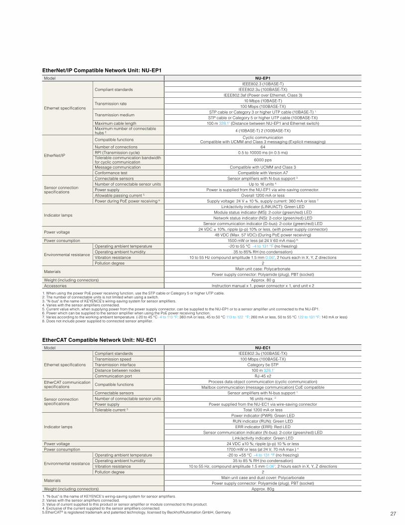
27
EtherNet/IP Compatible Network Unit: NU-EP1Model NU-EP1
Ethernet specifications
Compliant standardsIEEE802.3 (10BASE-T)
IEEE802.3u (100BASE-TX)IEEE802.3af (Power over Ethernet, Class 3)
Transmission rate10 Mbps (10BASE-T)
100 Mbps (100BASE-TX)
Transmission mediumSTP cable or Category 3 or higher UTP cable (10BASE-T) 1.
STP cable or Category 5 or higher UTP cable (100BASE-TX)Maximum cable length 100 m 328.1' (Distance between NU-EP1 and Ethernet switch)Maximum number of connectable hubs 2. 4 (10BASE-T) 2 (100BASE-TX)
EtherNet/IP
Compatible functions Cyclic communicationCompatible with UCMM and Class 3 messaging (Explicit messaging)
Number of connections 64RPI (Transmission cycle) 0.5 to 10000 ms (in 0.5 ms)Tolerable communication bandwidth for cyclic communication 6000 pps
Message communication Compatible with UCMM and Class 3Conformance test Compatible with Version A7
Sensor connection specifications
Connectable sensors Sensor amplifiers with N-bus support 3.
Number of connectable sensor units Up to 16 units 4.
Power supply Power is supplied from the NU-EP1 via wire-saving connector.Allowable passing current 5. Overall 1200 mA or lessPower during PoE power receiving 6. Supply voltage: 24 V ± 10 %, supply current: 360 mA or less 7.
Indicator lamps
Link/activity indicator (LINK/ACT): Green LEDModule status indicator (MS): 2-color (green/red) LEDNetwork status indicator (NS): 2-color (green/red) LED
Sensor communication indicator (D-bus): 2-color (green/red) LED
Power voltage24 VDC ± 10%, ripple (p-p) 10% or less, (with power supply connector)
48 VDC (Max. 57 VDC) (During PoE power receiving)Power consumption 1500 mW or less (at 24 V 60 mA max) 8.
Environmental resistance
Operating ambient temperature -20 to 55 °C -4 to 131 °F (no freezing)Operating ambient humidity 35 to 85% RH (no condensation)Vibration resistance 10 to 55 Hz compound amplitude 1.5 mm 0.06", 2 hours each in X, Y, Z directionsPollution degree 2
MaterialsMain unit case: Polycarbonate
Power supply connector: Polyamide (plug), PBT (socket)Weight (including connectors) Approx. 80 gAccessories Instruction manual x 1, power connector x 1, end unit x 2
1. When using the power PoE power receiving function, use the STP cable or Category 5 or higher UTP cable.2. The number of connectable units is not limited when using a switch.3. "N-bus" is the name of KEYENCE's wiring-saving system for sensor amplifiers.4. Varies with the sensor amplifiers connected.5. Current value which, when supplying power from the power supply connector, can be supplied to the NU-EP1 or to a sensor amplifier unit connected to the NU-EP1.6. Power which can be supplied to the sensor amplifier when using the PoE power receiving function.7. Varies according to the working ambient temperature. (-20 to 45 °C -4 to 113 °F: 360 mA or less, 45 to 50 °C 113 to 122 °F: 260 mA or less, 50 to 55 °C 122 to 131 °F: 140 mA or less)8. Does not include power supplied to connected sensor amplifier.
EtherCAT Compatible Network Unit: NU-EC1Model NU-EC1
Ethernet specifications
Compliant standards IEEE802.3u (100BASE-TX)Transmission speed 100 Mbps (100BASE-TX)Transmission interface Category 5e STPDistance between nodes 100 m 328.1'Communication port RJ-45 x2
EtherCAT communication specifications Compatible functions
Process data object communication (cyclic communication)Mailbox communication (message communication) CoE compatible
Sensor connection specifications
Connectable sensors Sensor amplifiers with N-bus support 1.
Number of connectable sensor units 16 units max. 2.
Power supply Power supplied from the NU-EC1 via wire-saving connectorTolerable current 3. Total 1200 mA or less
Indicator lamps
Power indicator (PWR): Green LEDRUN indicator (RUN): Green LED
ERR indicator (ERR): Red LEDSensor communication indicator (N-bus): 2-color (green/red) LED
Link/activity indicator: Green LEDPower voltage 24 VDC ±10 %; ripple (p-p) 10 % or lessPower consumption 1700 mW or less (at 24 V, 70 mA max.) 4.
Environmental resistance
Operating ambient temperature -20 to +55 °C -4 to 131 °F (no freezing)Operating ambient humidity 35 to 85 % RH (no condensation)Vibration resistance 10 to 55 Hz, compound amplitude 1.5 mm 0.06", 2 hours each in X, Y, Z directionsPollution degree 2
MaterialsMain unit case and dust cover: Polycarbonate
Power supply connector: Polyamide (plug), PBT (socket)Weight (including connectors) Approx. 80g
1. "N-bus" is the name of KEYENCE's wiring-saving system for sensor amplifiers.2. Varies with the sensor amplifiers connected.3. Value of current supplied to this product or sensor amplifier or module connected to this product.4. Exclusive of the current supplied to the sensor amplifiers connected.5.EtherCAT® is registered trademark and patented technology, licensed by BeckhoffAutomation GmbH, Germany.
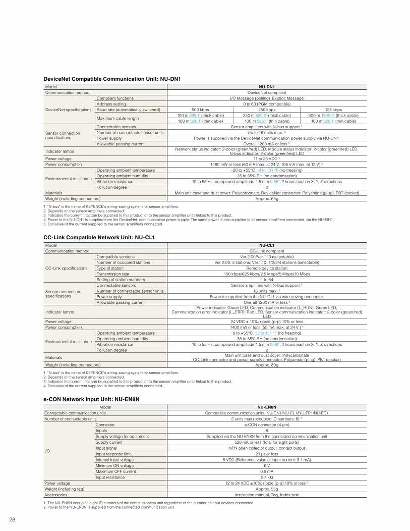
28
DeviceNet Compatible Communication Unit: NU-DN1Model NU-DN1Communication method DeviceNet compliant
DeviceNet specifications
Compliant functions I/O Message (polling) Explicit MessageAddress setting 0 to 63 (PGM compatible)Baud rate (automatically switched) 500 kbps 250 kbps 125 kbps
Maximum cable length100 m 328.1' (thick cable) 250 m 820.2' (thick cable) 500 m 1640.4' (thick cable)100 m 328.1' (thin cable) 100 m 328.1' (thin cable) 100 m 328.1' (thin cable)
Sensor connection specifications
Connectable sensors Sensor amplifiers with N-bus support 1.
Number of connectable sensor units Up to 16 units max. 2.
Power supply Power is supplied via the DeviceNet communication power supply via NU-DN1.Allowable passing current Overall 1200 mA or less 3.
Indicator lamps Network status indicator: 2-color (green/red) LED, Module status indicator: 2-color (green/red) LED, N-bus indicator: 2-color (green/red) LED
Power voltage 11 to 25 VDC 4.
Power consumption 1480 mW or less (60 mA max. at 24 V, 106 mA max. at 12 V) 5.
Environmental resistance
Operating ambient temperature -20 to +55°C -4 to 131 °F (no freezing)Operating ambient humidity 35 to 85% RH (no condensation)Vibration resistance 10 to 55 Hz, compound amplitude 1.5 mm 0.06", 2 hours each in X, Y, Z directionsPollution degree 2
Materials Main unit case and dust cover: Polycarbonate, DeviceNet connector: Polyamide (plug), PBT (socket)Weight (including connectors) Approx. 65g
1. "N-bus" is the name of KEYENCE's wiring-saving system for sensor amplifiers.2. Depends on the sensor amplifiers connected.3. Indicates the current that can be supplied to this product or to the sensor amplifier units linked to this product.4. Power to the NU-DN1 is supplied from the DeviceNet. communication power supply. The same power is also supplied to all sensor amplifiers connected, via the NU-DN1.5. Exclusive of the current supplied to the sensor amplifiers connected.
CC-Link Compatible Network Unit: NU-CL1Model NU-CL1Communication method CC-Link compliant
CC-Link specifications
Compatible versions Ver.2.00/Ver.1.10 (selectable)Number of occupied stations Ver.2.00: 3 stations; Ver.1.10: 1/2/3/4 stations (selectable)Type of station Remote device stationTransmission rate 156 kbps/625 kbps/2.5 Mbps/5 Mbps/10 MbpsSetting of station numbers 1 to 64
Sensor connection specifications
Connectable sensors Sensor amplifiers with N-bus support 1.
Number of connectable sensor units 16 units max. 2.
Power supply Power is supplied from the NU-CL1 via wire-saving connector.Allowable passing current Overall 1200 mA or less 3
Indicator lampsPower indicator: Green LED, Communication indicator (L_RUN): Green LED,
Communication error indicator (L_ERR): Red LED, Sensor communication indicator: 2-color (green/red) LED
Power voltage 24 VDC ± 10%; ripple (p-p) 10% or lessPower consumption 1400 mW or less (55 mA max. at 24 V ) 4.
Environmental resistance
Operating ambient temperature 0 to +55°C 32 to 131 °F (no freezing)Operating ambient humidity 35 to 85% RH (no condensation)Vibration resistance 10 to 55 Hz, compound amplitude 1.5 mm 0.06", 2 hours each in X, Y, Z directionsPollution degree 2
Materials Main unit case and dust cover: PolycarbonateCC-Link connector and power supply connector: Polyamide (plug), PBT (socket)
Weight (including connectors) Approx. 80g
1. "N-bus" is the name of KEYENCE's wiring-saving system for sensor amplifiers.2. Depends on the sensor amplifiers connected.3. Indicates the current that can be supplied to this product or to the sensor amplifier units linked to this product.4. Exclusive of the current supplied to the sensor amplifiers connected.
e-CON Network Input Unit: NU-EN8NModel NU-EN8N
Connectable communication units Compatible communication units, NU-DN1/NU-CL1/NU-EP1/NU-EC1Number of connectable units 2 units max.(occupied ID numbers: 8) 1.
I/O
Connector e-CON connector (4-pin)Inputs 8Supply voltage for equipment Supplied via the NU-EN8N from the connected communication unitSupply current 520 mA or less (total for eight ports)Input signal NPN open collector output, contact outputInput response time 20 µs or lessInternal input voltage 8 VDC (Reference value of input current: 3.1 mA)Minimum ON voltage 6 VMaximum OFF current 0.9 mAInput resistance 2.4 kΩ
Power voltage 12 to 24 VDC ±10%; ripple (p-p) 10% or less 2.
Weight (including tag) Approx. 55gAccessories Instruction manual, Tag, Index seal
1. The NU-EN8N occupies eight ID numbers of the communication unit regardless of the number of input devices connected.2. Power to the NU-EN8N is supplied from the connected communication unit.
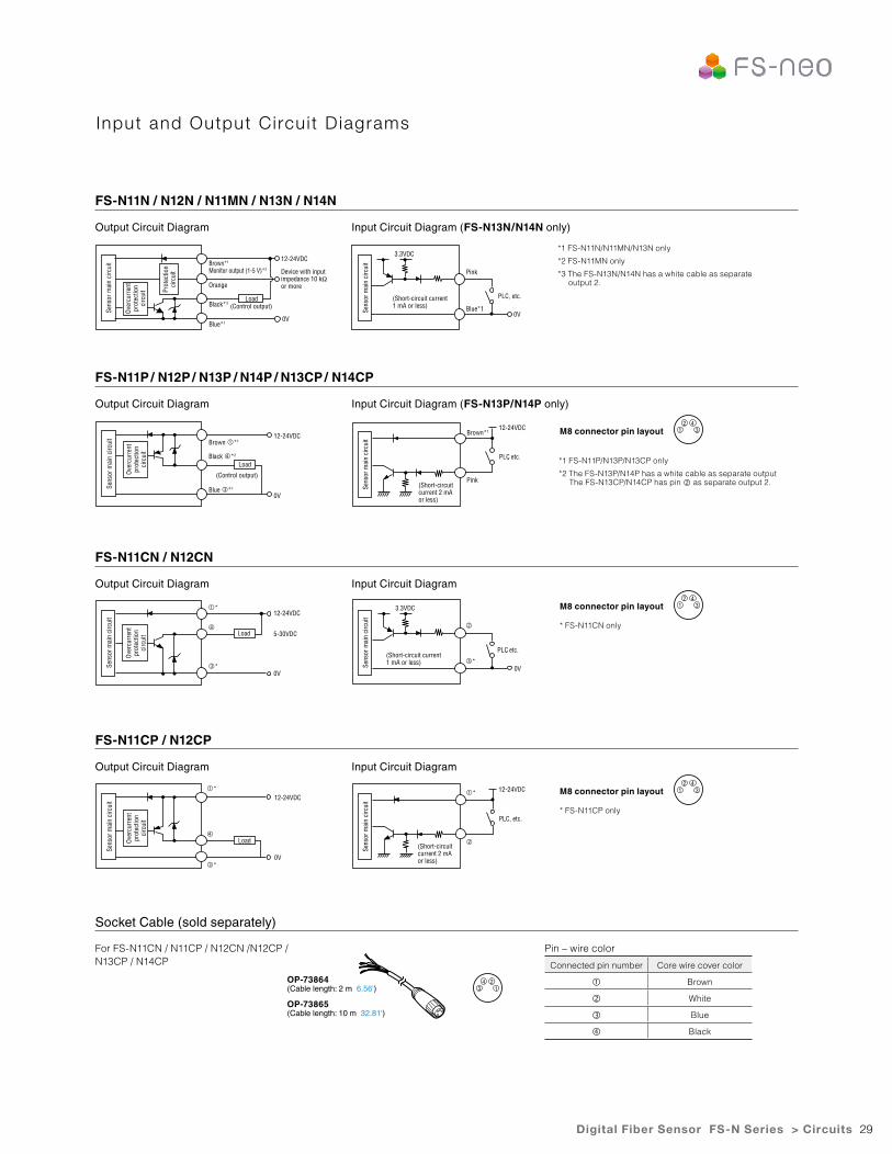
29
Input and Output Circui t D iagrams
Output Circuit Diagram
Output Circuit Diagram
Output Circuit Diagram
Output Circuit Diagram
For FS-N11CN / N11CP / N12CN /N12CP / N13CP / N14CP
Input Circuit Diagram (FS-N13N/N14N only)
Input Circuit Diagram (FS-N13P/N14P only)
Input Circuit Diagram
Input Circuit Diagram
FS-N11N / N12N / N11MN / N13N / N14N
FS-N11P / N12P / N13P / N14P / N13CP / N14CP
FS-N11CN / N12CN
FS-N11CP / N12CP
Socket Cable (sold separately)
*1 FS-N11N/N11MN/N13N only
*2 FS-N11MN only
*3 The FS-N13N/N14N has a white cable as separate output 2.
*1 FS-N11P/N13P/N13CP only
*2 The FS-N13P/N14P has a white cable as separate output The FS-N13CP/N14CP has pin as separate output 2.Pink
Brown*112-24VDC
PLC, etc.
(Short-circuit current 2 mA or less)
M8 connector pin layout 12 4
3
* FS-N11CN only
M8 connector pin layout 12 4
3
* FS-N11CP only
M8 connector pin layout 12 4
3
12-24VDC
5-30VDC
0V
*
*
PLC, etc.
3.3VDC
0V
*
Load
12-24VDC
0V
*
*
12-24VDC
PLC, etc.
*
OP-73865(Cable length: 10 m 32.81')
Digital Fiber Sensor FS-N Series > Circuits
(Control output)
12-24VDC
Device with input impedance 10 kΩ or more
0V
Orange
Brown*1
Monitor output (1-5 V)*2
Black*3
Blue*1
Pink
Blue*1
(Short-circuit current 1 mA or less)
PLC, etc.
3.3VDC
0VSens
or m
ain
circ
uit
Load
12-24VDC
0V
(Control output)
Brown *1
Black *2
Blue *1Sens
or m
ain
circ
uit
Over
curr
ent
prot
ectio
n ci
rcui
t
Sens
or m
ain
circ
uit
(Short-circuit current 1 mA or less)Se
nsor
mai
n ci
rcui
t
(Short-circuit current 2 mA or less)
Sens
or m
ain
circ
uit
34 2
1
Sens
or m
ain
circ
uit
Over
curr
ent
prot
ectio
n ci
rcui
t
OP-73864(Cable length: 2 m 6.56')
Pin – wire color
Connected pin number Core wire cover color
Brown
White
Blue
Black
Sens
or m
ain
circ
uit
Prot
ectio
n ci
rcui
t
Over
curr
ent
prot
ectio
n ci
rcui
t
Load
Sens
or m
ain
circ
uit
Over
curr
ent
prot
ectio
n ci
rcui
t Load
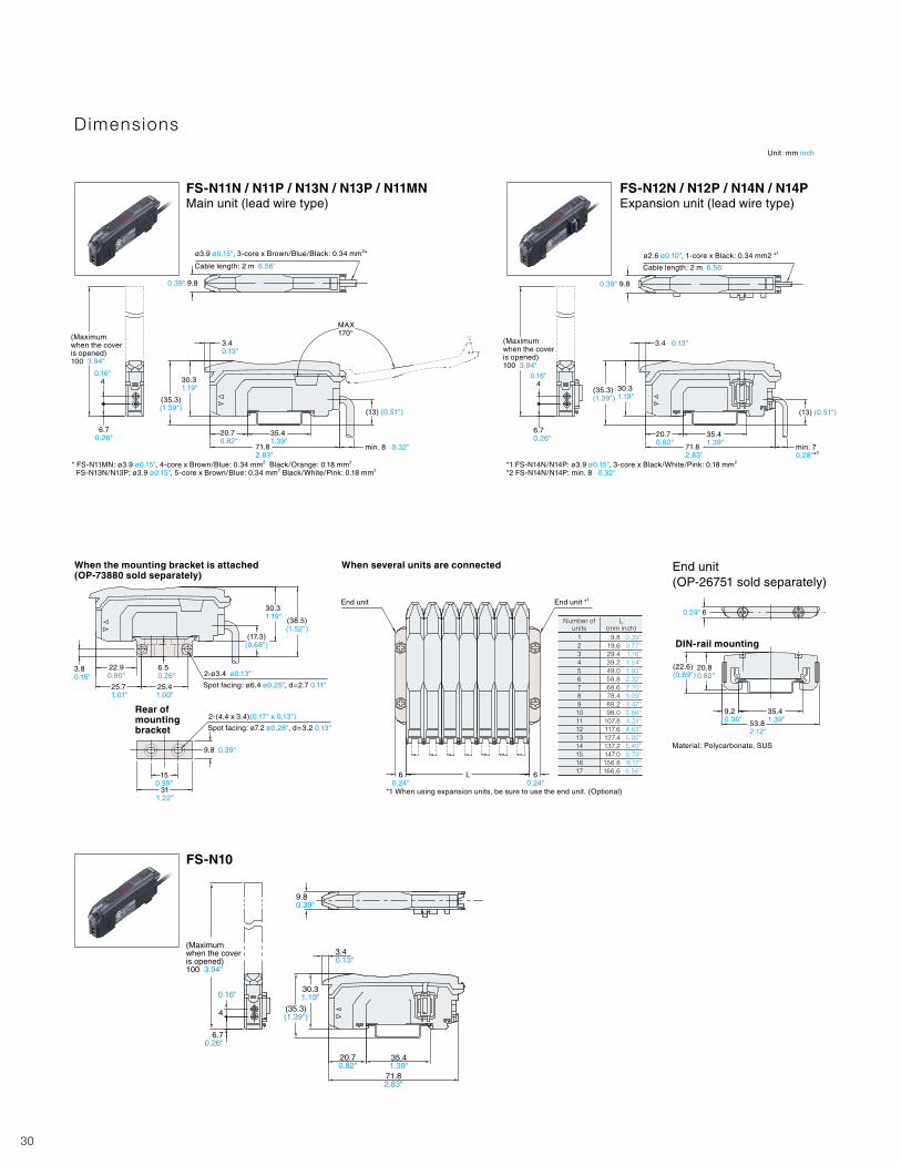
30
Dimensions
FS-N11N / N11P / N13N / N13P / N11MNMain unit (lead wire type)
FS-N10
FS-N12N / N12P / N14N / N14PExpansion unit (lead wire type)
Cable length: 2 m 6.56' Cable length: 2 m 6.56'
0.39" 9.8 0.39" 9.8
0.16"4
0.16"4
6.70.26"
6.70.26"
3.4 0.13"
3.4 0.13"
30.31.19" 30.3
1.19"
20.70.82"
20.70.82"
71.82.83"
71.82.83"
35.41.39"
35.41.39"
MAX170°
(35.3)(1.39")
(35.3)(1.39")
(13) (0.51") (13) (0.51")
min. 8 0.32"
Unit: mm inch
min. 7 0.28"*2
(Maximum when the cover is opened) 100 3.94"
(Maximum when the cover is opened) 100 3.94"
ø3.9 ø0.15", 3-core x Brown/Blue/Black: 0.34 mm2* ø2.6 ø0.10", 1-core x Black: 0.34 mm2 *1
* FS-N11MN: ø3.9 ø0.15", 4-core x Brown/Blue: 0.34 mm2 Black/Orange: 0.18 mm2
FS-N13N/N13P: ø3.9 ø0.15", 5-core x Brown/Blue: 0.34 mm2 Black/White/Pink: 0.18 mm2*1 FS-N14N/N14P: ø3.9 ø0.15", 3-core x Black/White/Pink: 0.18 mm2
*2 FS-N14N/N14P: min. 8 0.32"
When the mounting bracket is attached (OP-73880 sold separately)
DIN-rail mounting
When several units are connected End unit (OP-26751 sold separately)
3.80.15"
6.50.26"
9.8 0.39"
60.24"
60.24"
0.24" 6
L150.59"
311.22"
22.90.90"
25.71.01"
25.41.00"
2-ø3.4 ø0.13"
2-(4.4 x 3.4)(0.17" x 0.13")
Spot facing: ø6.4 ø0.25", d=2.7 0.11"
Spot facing: ø7.2 ø0.28", d=3.2 0.13"
30.31.19"
End unit End unit *1
(17.3)(0.68")
(38.5)(1.52")
(22.6)(0.89")
20.80.82"
9.20.36"
35.41.39"53.8
2.12"
*1 When using expansion units, be sure to use the end unit. (Optional)
Material: Polycarbonate, SUS
Number of units
L (mm inch)
1 9.8 0.39"2 19.6 0.77"3 29.4 1.16"4 39.2 1.54"5 49.0 1.93"6 58.8 2.32"7 68.6 2.70"8 78.4 3.09"9 88.2 3.47"10 98.0 3.86"11 107.8 4.24"12 117.6 4.63"13 127.4 5.02"14 137.2 5.40"15 147.0 5.79"16 156.8 6.17"17 166.6 6.56"
Rear of mounting bracket
(Maximum when the cover is opened) 100 3.94"
3.40.13"
30.31.19"
6.70.26"
4
0.16"
(35.3)(1.39")
71.82.83"
20.70.82"
35.41.39"
9.80.39"
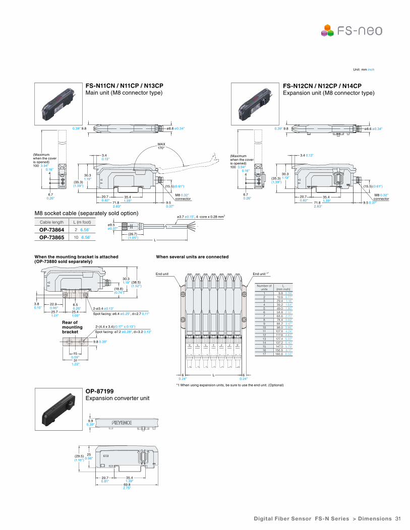
31
FS-N11CN / N11CP / N13CPMain unit (M8 connector type)
OP-87199Expansion converter unit
FS-N12CN / N12CP / N14CPExpansion unit (M8 connector type)
0.39" 9.8 0.39" 9.8ø8.6 ø0.34" ø8.6 ø0.34"
0.16"4
0.16"4
6.70.26"
6.70.26"
3.4 0.13"
3.4 0.13"
30.31.19"
30.31.19"
20.70.82"
20.70.82"
71.82.83"
71.82.83"
35.41.39"
35.41.39"
MAX170°
(35.3)(1.39")
(35.3)(1.39")
(15.5)(0.61") (15.5)(0.61")
9.5 0.37"
9.5 0.37"
ø3.7 ø0.15", 4 -core x 0.28 mm2
L
M8 0.32"connector
M8 0.32"connector
(Maximum when the cover is opened) 100 3.94"
(Maximum when the cover is opened) 100 3.94"
M8 socket cable (separately sold option)
Cable length L (m foot)
OP-73864 2 6.56'
OP-73865 10 6.56'
ø9.5ø0.37"
(26.7)(1.05")
When the mounting bracket is attached (OP-73880 sold separately)
When several units are connected
3.80.15"
6.50.26"
9.8 0.39"
60.24"
60.24"
L
150.59"
311.22"
22.90.90"25.71.01"
25.41.00"
2-ø3.4 ø0.13"
2-(4.4 x 3.4)(0.17" x 0.13")
Spot facing: ø6.4 ø0.25", d=2.7 0.11"
Spot facing: ø7.2 ø0.28", d=3.2 0.13"
30.31.19"
End unit End unit *1
(18.8)(0.74")
(38.5)(1.52")
*1 When using expansion units, be sure to use the end unit. (Optional)
Number of units
L (mm inch)
1 9.8 0.39"2 19.6 0.77"3 29.4 1.16"4 39.2 1.54"5 49.0 1.93"6 58.8 2.32"7 68.6 2.70"8 78.4 3.09"9 88.2 3.47"10 98.0 3.86"11 107.8 4.24"12 117.6 4.63"13 127.4 5.02"14 137.2 5.40"15 147.0 5.79"16 156.8 6.17"17 166.6 6.56"
Digital Fiber Sensor FS-N Series > Dimensions
Rear of mounting bracket
Unit: mm inch
9.9
25(29.5)
20.7 35.4
69.8
0.39"
0.98"(1.16")
0.81" 1.39"
2.75"
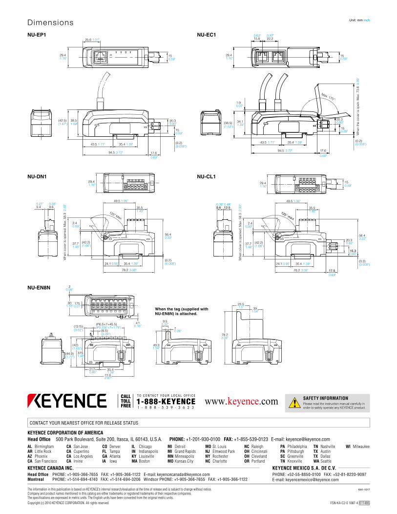
www.keyence.com
FSN-KA-C2-E 1087-4 611486 Copyright (c) 2010 KEYENCE CORPORATION. All rights reserved.
E-mail: [email protected]
E-mail: [email protected] E-mail: [email protected]
NU-EN8N
NU-EP1 NU-EC1
NU-DN1 NU-CL1
70.28"
9.50.37"
49.31.94"
78.23.08"
391.54"
25.51.0"When the tag (supplied with
NU-EN8N) is attached.
(13.15)(0.52")
(P6.5×7=45.5)(P0.256"×7=1.79")
(6.5)(0.26")
37.51.48"
(42)(1.65")
(44.9)(1.77")
21.7 35.40.85" 1.39"
72.82.87"
1.750.07"
20.08"
301.18"
4.10.16"
25.6 1.01"
43.5 1.71" 35.4 1.39"
94.5 3.72" 17.60.69"
(0.2)
(42.5) 38.5(1.67") 1.52" (38.5)
(1.52")
20.30.80"
20.30.80"
20.30.80"
29.41.16"
29.41.16"
15
(0.008")
(0.2)(0.008")
0.59"
150.59"
150.59"
150.59"
150.59"
22.2
34.1
1.9
1.34"
0.07"
94.5
43.5
15.8 0.87"0.62"
Whe
n th
e co
ver i
s op
en: M
ax. 7
3.6
0.8
0"
Max. 170°
35.4
3.72"
1.71" 1.39"
17.6
0.69"
2.4
37.7
56.42.22"
(42.2)
0.09"
1.48" (1.66")
5.4 9.60.21" 0.38"
49.5 1.95"
24.1 35.4
78.2
0.95" 1.39"
3.08"
24.1 35.4
78.2
0.95" 1.39"
3.08"
35.51.40"
49.5 1.95"
35.51.40"125° Max.
Whe
n co
ver i
s op
ened
: Max
. 58.
3 2
.30"
2.4
37.7 (42.2)
0.09"
1.48" (1.66")
Whe
n co
ver i
s op
ened
: Max
. 58.
3 2
.30"
(0.2)(0.008")
56.42.22"
(0.2)(0.008")
29.41.16" 29.4
1.16"
9.6 12.50.38" 0.49"
0.60"15.3
125° ma x
17.50.69"
Dimensions Unit: mm inch