Embed Size (px)
Citation preview

International Journal of Engineering Research & Science (IJOER) ISSN: [2395-6992] [Vol-2, Issue-3, March- 2016]
Page | 25
Digital Filter Design of Infinite Impulse Response (IIR)
Infrasound to Detect Fetal Heart Rate Mochamad Karjadi
1, Nur Sultan Salahuddin
2, Eri Prasetyo Wibowo
3, Hamzah Afandi
4
1Department of Electrical Engineering, Gunadarma University, Jakarta 2,3,4
Department of System Computer, Gunadarma University, Jakarta
Abstract— One way of checking on a pregnant woman is inspection using ultrasonic wave Doppler technique, this check is
done by putting Doppler ultrasonic waves over the abdomen to capture the heart beat of the fetus with the addition of the gel
material, there sebaga in pregnant women who are allergic to the gel material. Alternatively we can use the technique in
frassonik waves. With a digital design II Chebyshev band pass filter with a frequency range of 2-3Hz, the heart rate of
pregnant women with fetal heart beat can be distinguished. With the help of software MatLab and Xilink will be resolved in
the manufacture of digital filter terser but. The simulation results with the software quite satisfactory.
Keywords— heartbeat, infrasound.
I. INTRODUCTION
1.1 Background Research
Since the beginning of pregnancy, it is advisable to conduct regular control to the nearest obstetrician. During the inspection
control is highly dependent on the doctor or clinic in question, but in general here is given the type of examinations
performed and it is necessary to ensure the health of mother and baby during pregnancy to child birth. One of these checks is
the examination with Doppler ultrasound, this check is done by putting Doppler ultrasonic waves over the abdomen to
capture the heart beat of the fetus with the addition of the gel material, there sebaga in pregnant women who are allergic to
the gel material.
1.2 Some researchers History:
[G.S. Dawes, G.H.A. Visser, J.D.S. Goodman, C.W.G. Redman: 1981] ultrasonic sensors are used, compared to
ultrasound-based technique with electro cardiography A direct and noted that the short-term index calculation error(STV)
variability(calculated as the beat-to-beat changes) caused by the approach of ultrasoundreaches100%.
[G.W. Lawson, G.S. Dawes, C.W.G. Redman: 1982] uses ultrasonic sensors to do the same, but for other types of fetal
monitor, download the error log many of the calculations (200%). In both cases the signal is recorded using a fetal monitor
from generation before hand, which implement peak detection method to identify fetal heart rate. In further experiments,
using a fetal monitor with the new generation of the auto correlation function.
[G.W. Lawson, R. Belcher, G.S. Dawes, C.W.G. Redman : 1983] gained a lot of errors is low on TV ratings: -35%. A
minus sign means that the pen-ultrasonic approach decreased short-term variability in relation to the FECG.
[J. Wrobel, J. Jezewski, Dawid Roj, Tomasz P., Robert C., Adam : 2010]Estimated instantaneous reliability of the fetal
heart rate (FHR) is influenced by autocorrelation techniques commonly used in the channel Doppler ultrasound fetal moni-
tor today. Has noted greatly reduce the short-term variability, which is quite surprising because as has been shown
previously, determine fetal monitor FHR signal with satisfactory accuracy in relation to electro cardiography direct reference
to the fetus. The purpose of this study was to identify the source kesala-han caused by a commonly used approach. Results
may be possible to developed the method for the correction of FHR variability describes the quantitative index for certain
types of fetal monitor, which relies on the proposed cancellation of the constant error correction component, which has been
assigned to an average properties of the autocorrelation function. Although the random error component remaining after
correction is still not very satisfactory considering the instantaneous values, significanting katan Pen-track assessment of the
reliability of the measurement of fetal heart rate variability in global cases confirmed one hour
Fetal heart beat sound (relatively weak), then actually using a sensitive microphone, the fetal heart can be detected by
strengthening the signal generated by the microphone. The problem is no fetal heart beat in addition there is also another's
heart beat that results in a stronger heart beat intensity. The frequency of fetal heart rate is higher than the heart beat of the
International Journal of Engineering Research & Science (IJOER) ISSN: [2395-6992] [Vol-2, Issue-3, March- 2016]
Page | 26
mother (fetal heart rate is 120-160beats per minute (about2-3Hz) while the heart of the mother around 80-90 beats per
minute), then by technical filtering, then the heart beat the mother can be filtered in order to obtain only the fetal heartbeat.
Therefore, through this study, researchers will propose to design a digital filter (band pass filter) using approaches in
frasound (2-3 Hz) are not widely used to monitor fetal heart beat rate, using Simulink and XiLink FPGA tool.
II. LITERATURE REVIEW
A filter is a circuit that is designed to skip a frequency band ter-course while weakening all signals outside this band. The
digital filter is an implementation of the algo-Ritma mathematics into the hardware and / or software that operates on an
input digital signal for the purpose of filtering is achieved. Jarin-gan-network regular filter is active or passive. Tissues of
passive filters contain only prisoners, inductor, and capacitor alone. Active filters menggunalan transistor or op-amp plus ta-
hanan, inductors, and capacitors. But ja-rang inductors used in filters are active, because uku-rannya large and expensive and
could have Kompo-nen-component in a large persistence. With Filter we can filter out the frequency we want, there are
several types of filters. As we know, based on the frequency that is passed, in general filter terbagi into 4 yak-ni Low Pass
Filter; High Pass Filter; Band Pass Filter; and Band Stop Filter. IIR filters have infinite impulse response filter where the
output is a function of input current conditions, previous input and output at an earlier time (causal), better known as
recursive filters that involve pros-ice feedback and feed forward. For this study, researchers used a type of IIR digital filter.
IIR filter is one type of digital filters are widely used in applications of Digital Signal Processing (DSP). IIR stands for
Infinite Impulse Response. Why is it called the re-sponge infinite impulse (infinite)? Due to the feedback in the filter, if you
are me-enter an impulse (ie a signal '1' followed by many signals '0'), then on his output will continue to oscillate for their
feedback, although in practice it will be lost on someday. Advantages include IIR filter-kan is a need for fewer coefficient for
frequency response-uensi steep so as to reduce the amount of computation time. In general, the transfer function of the digital
filter IIR (Infinite Impulse Response) Order N [Smith, 1995] are as follows:
(1) The equation is different is expressed as the equation:
(2)
Input-output equation IIR filter is as follows:
(3)
Based IIR filter design techniques can be categorized in several design techniques. While the filters FIR (Finite Impulse
Response) basically have two methods of design, namely the window (the window) and pitajamak the transition band
(multiband with transition bands). IIR digital filter design techniques are based on bilinear transformation from analog
transfer function prototype. Ana-log transfer function is typically one of the type of transfer function: But-terworth,
Chebyshev Type 1, Type 2 Chebyshev and Elliptic (or Cauer). The difference between these filter types can be explained by
looking at the lower pass filter (lowpass) analogous to those described below [Antoni-ou, 1993].
a. Butterworth transfer function has escaped under maximum flat magnitude response and magnitude response berku-
rang horizontally with air-tarnbah frequency.
b. The transfer function passes under Chebyshev Type I had a magnitude responsive to the ri-ak equilibrium on tape
passes and a magnitude response is reduced horizontally with increasing frequency in the outer tape passes.

International Journal of Engineering Research & Science (IJOER) ISSN: [2395-6992] [Vol-2, Issue-3, March- 2016]
Page | 27
c. The transfer function passes under Chebyshev Type II has a magnitude response reduced horizontally on tape passes
with increasing frequency and magnitude response ripple equilibrium pad prevent a tape.
d. The transfer function passes under Elliptic mempu-nyai ripple magnitude response of equilibrium on the second
tape, ribbon or ribbon prevent escapes.
2.1 Advantages of Digital Filters: 1
1. The working area is wide (can be frequency for low and high) with a sampling frequency menga-tour. It can even be
used in areas Very Low Frequency, where the analog filter is difficult to apply in this frequency area, so it can be
used for applications elektroni-ka biomedical.
2. Can provide phase response is absolutely linear.
3. Because the digital filter implementations can use the programmable pro-cessor, the frequency response can be
changed automatically.
4. Some of the input signal (several chan-nel) can be filtered by a digital filter without doubling the hardware for each
channel.
5. With the development of technology and fab-rikasi VLSI chip, power consumption and smaller digital filter can
reduce the cost of production.
6. Advantages include IIR filter requires fewer coefficients for steep frequency response so as to reduce the amount of
computation time.
7. In the Order IIR filter low frequency response that can produce sharp / steep (almost close to ideal).
8. The digital filter is very stable against the effects of temperature and time.
9. The digital filter can handle signals with low fre-keunsi accurate.
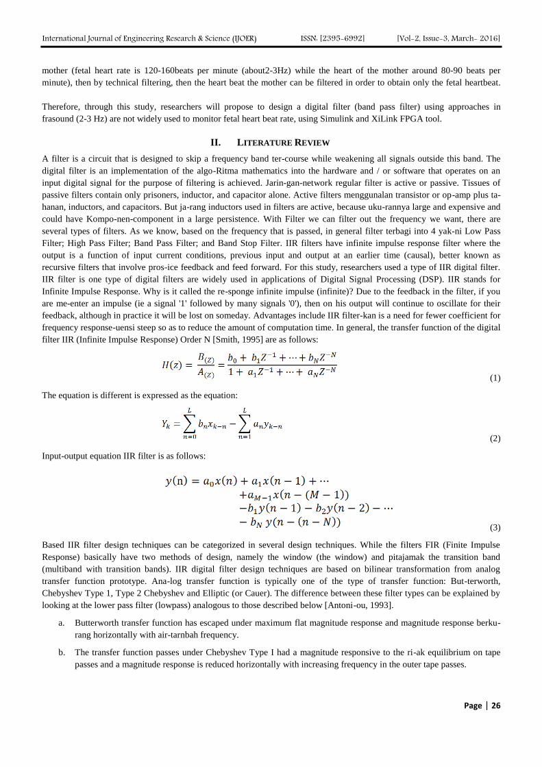
2.2 Digital Filter Chebyshev
Chebyshev filter is a part of the analog or digital type filter that has a sharper roll-off and more ripple in the passband (type I)
or stopband ripple (type II) than the Butterworth filter. Chebyshev filter has the property to minimize the error between the
ideal and the actual characteristics of the filter for the filter range, but the ripple in the passband. This type of filter is named
in honor of a scientist named Pafnuty Chebyshev, due to their mathematical characteristics derived from the Chebyshev
polynomials. Due to the passband ripple inherent in Chebyshev filter, a filter that has a smooth response in the passband but a
more irregular response in the stopband are preferred for some applications [Williams, 2006]. To find or search order (order)
n on Chebyshev, use the following equation
(4)
(5)
FIGURE. 1. CHEBYSHEV TIPE I LOWPASS FILTER [IFEACHOR, 202]
International Journal of Engineering Research & Science (IJOER) ISSN: [2395-6992] [Vol-2, Issue-3, March- 2016]
Page | 28
FIGURE. 2. CHEBYSHEV TIPE II LOWPASS FILTER [IFEACHOR, 202]
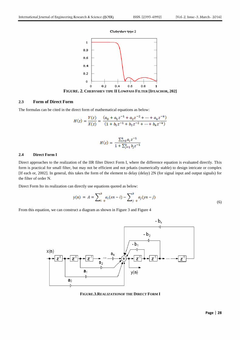
2.3 Form of Direct Form
The formulas can be cited in the direct form of mathematical equations as below:
2.4 Direct Form I
Direct approaches to the realization of the IIR filter Direct Form I, where the difference equation is evaluated directly. This
form is practical for small filter, but may not be efficient and not prkatis (numerically stable) to design intricate or complex
[If each or, 2002]. In general, this takes the form of the element to delay (delay) 2N (for signal input and output signals) for
the filter of order N.
Direct Form Ito its realization can directly use equations quoted as below:
(6)
From this equation, we can construct a diagram as shown in Figure 3 and Figure 4
FIGURE.3.REALIZATIONOF THE DIRECT FORM I

International Journal of Engineering Research & Science (IJOER) ISSN: [2395-6992] [Vol-2, Issue-3, March- 2016]
Page | 29
FIGURE. 4. SCHEMATIC DIAGRAM OF AN IIR FILTER
2.5 Direct Form II
Alternatively Direct Form II only requires N delay units, where N is the order of the filter, could potentially have as many as
half a Direct Form I. This structure is obtained by reversing the order of the numerator and denominator of parts Direct Form
I, because the two systems are actually linear, and commutative apply for the property. Kemuadian, one will see that there are
two columns of delay (delay) ie z-1 utilizing the center nets, and these can be combined because there were a lot of repeats.
The disadvantage is that Direct Form II increases the chances of arithmetic (calculation) over-flow filter or a high Q
resonance [Ruggiero, 1982]. It has been proven that Q increases, the noise around these two forms of topology increases
indefinitely. This is because, conceptually first signal passes through the filter all poles (which can usually improve gai at the
resonance frequency) before generating saturation, then pass through a filter that is all zero (which often weakens as many as
half of all poles bracing). Realizations of Direct Form II can dikutif in mathematical terms:
Y(z) = H(z) . X(z)
Y(z) = N(z) . W(z)
(7)
Y(z) = N(z) . W(z)

International Journal of Engineering Research & Science (IJOER) ISSN: [2395-6992] [Vol-2, Issue-3, March- 2016]
Page | 30
From the equation above, we can construct a diagram as in Figure6 below:
FIGURE5. REALIZATION OF THEDIRECT FORM II
2.6 Research Objectives
The specific objectives of this program are:
1. Creating a digital filter design type of Band Pass Filters IIR Chebyshev II order 4 so that it candiimplcment as ikan
on the FPGA board.
2. Realizing a digital infrasonic filter that can later be used for development, detection of fetal heart beat in the form of
SoC (System on Chip).
3. Program MATLAB is used to memu-dahkan seek coefficient digital filter design.
4. Program Xlink is used for the simulation of digital filter design MatLab and to mens in kronasikan (match) results.
2.7 Research Methods
2.7.1 Digital Filter Design
This section discusses the design, designing band pass Chebyshev digital filter by performing mathematical calculations. To
be implemented in a XilinxIse14.2 with VHDL is a hardware description language standard for VHSIC. Hardware
description language used in electronic design automation to describe digital and mixed-signal systems such as the field
programmable gate array and integrated circuits. Block diagram of the overall system can be described as below:
XLINK ISE
Download to FPGASpartan-3E
Program MatLab
Simulink Model
Code Generation(sysgen / accel DSP)
RTL DHL CORE
Bitstream
Hardware SimulationModelSim
FIGURE 6. BLOCK DIAGRAM GLOBAL RESEARCH

International Journal of Engineering Research & Science (IJOER) ISSN: [2395-6992] [Vol-2, Issue-3, March- 2016]
Page | 31
The location is on the pole Butterworth filter and the Chebyshev polynomial coefficients appropriate and have been obtained
and tabulated by Weinberg (see Table 1).
An abbreviated set of coefficients polynomial for Butterworth and Chebyshev functions presented here, some form of
polynomial factors have been calculated and tabulated. Polynomial given in the foundation needed to build a low-pass
transfer function. The general form of the transfer functions as in the table below:
TABLE1.
THE COEFFICIENT OF LOW-PASS FILTER POLYNOMIAL DENOMINATOR (DENOMINATOR POLYNOMIALS)
(8)
The coefficient of the denominator of the equation (8) are tabulated in Table to function for the Butterworth and Chebyshev
functions to four possible values of passband ripple (0.5 dB, 1 dB, 2 dB and 3 dB). The use of the filter order from k = 1 to k
= 5. If desired gain in dc numerator constant then have A0 = B0 (Note: the coefficient is defined according to the equation
(8) (6).
Creating a Digital Design Band-Pass Filter Chebyshev. To be able to operate on digital signal processing systems must have
a sampling rate of at least 2 x frequency data in accordance with the terms Nyquist, in this design used 200 Hz (fs). Bandpass
digital filter required specification, the system as follows:
International Journal of Engineering Research & Science (IJOER) ISSN: [2395-6992] [Vol-2, Issue-3, March- 2016]
Page | 32
Range band pass filter of 2 Hz to 3 Hz with attenuation that is still allowed no more than 3 dB at a frequency of two
sides of the ramp.
Attenuation should be less than 18 dB at the frequency of 1 Hz and 4 Hz.
The type of response required by the ripple Chebyshev 3 dB.
Looking folding frequency (f0) is f0 = fs / 2 = 200/2 = 100 Hz. There are two frequency of 2 Hz and 3 Hz to be selected
as a band-edge frequency as f1 and f3. For search, the values of the main and sub prime rates, the frequency will be
changed to a form of normalization,
v1 = f1/f0 = 2/100 =0.02 (9)
v3 = f3/f0 = 3/100 =0.03 (10)
b = v3- v1 = 0.03 – 0.02 = 0.01 (11)
va = fr1/f0 = 1/100 = 0.01 (12)
vb = fr2/f0 = 4/100 = 0.04 (13)
The center frequenciesv2are:
tan2
v2 =tan v1 tan v3 = tan x 0.02tan x 0.03
= tan (1,8)tan (2,7)
= 0.0314 x 0.0472
= 0.0015
tan v2 = 0.0385
v2 = 2,2048
v2 = 0.0245(14)
Transformation for the constants D and E with the assumption that λr = 1 rad/s.
So to λa and λb representing two analog frequencies, are as follows:
International Journal of Engineering Research & Science (IJOER) ISSN: [2395-6992] [Vol-2, Issue-3, March- 2016]
Page | 33
(17)
(18)
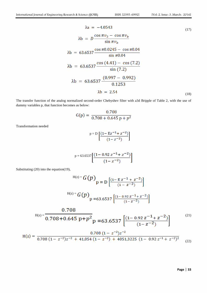
The transfer function of the analog normalized second-order Chebyshev filter with a3d Bripple of Table 2, with the use of
dummy variables p, that function becomes as below:
Transformation needed
p = D
p = 63.6537
Substituting (20) into the equation(19),
H(z) =
H(z) =
H(z) = (21)
(22)

International Journal of Engineering Research & Science (IJOER) ISSN: [2395-6992] [Vol-2, Issue-3, March- 2016]
Page | 34
(23)
the coefficient of the equation (23) are as follows:
TABLE 2
VALUE COEFFICIENT OF EQUATION (23)
No Koefisien Nilai Desimal Hexadesimal
1 A0 0.00017 17 0011
2 A2 -0.00034 -34 FFDE
3 A4 0.00017 17 0011
4 B1 -1,8123 -181230 D3C12
5 B2 2,7894 278940 4419C
6 B3 -1,7940 -179400 D4338
7 B4 0.96027 96027 1771B
X
+X
X
X
X
X
X
+
+
+
++
Divider 100000
Z-1
Z-1
Divider 100000
Z-1
Z-1
Z-1
Z-1
Z-1
Z-1
Din Fout
Clk
ResA0
A2
A4
B1
B2
B3
B4
FIGURE 7. REALIZATION FOR SYSTEMS OF EQUATIONS23
2.7.2 IIR filter Deployment Process
Analog input signal must first sample and digitally using ADC(analog-to-digital con-verter). The resulting binary numbers,
representing the values of consecutive samples of the input signal, will be transferred to the processors, which perform
numerical calculations on them. These calculations usually involving mathematical operations by downloading galikan input
values by a constant and Menam-even the same product. If necessary, result-Tungan perhi, who now represents the values of
the samples of the filtered signal, is output through a DAC (digital to analog converter) to convert the signal back to its
original analog form.
Modules are used for implements its-invest the IIR filter is as follows: Module Multiplication, Addition module, splitter
modules, and modules Reduction, that all of it was developed using the programming language VHDL.
International Journal of Engineering Research & Science (IJOER) ISSN: [2395-6992] [Vol-2, Issue-3, March- 2016]
Page | 35
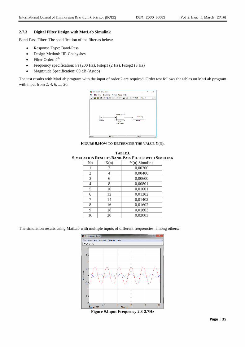
2.7.3 Digital Filter Design with MatLab Simulink
Band-Pass Filter: The specification of the filter as below:
Response Type: Band-Pass
Design Method: IIR Chebyshev
Filter Order: 4th
Frequency specification: Fs (200 Hz), Fstop1 (2 Hz), Fstop2 (3 Hz)
Magnitude Specification: 60 dB (Astop)
The test results with MatLab program with the input of order 2 are required. Order test follows the tables on MatLab program
with input from 2, 4, 6, ..., 20.
FIGURE 8.HOW TO DETERMINE THE VALUE Y(N).
TABLE3.
SIMULATION RESULTS BAND-PASS FILTER WITH SIMULINK
No X(n) Y(n) Simulink
1 2 0,00200
2 4 0,00400
3 6 0,00600
4 8 0,00801
5 10 0,01001
6 12 0,01202
7 14 0,01402
8 16 0,01602
9 18 0,01803
10 20 0,02003
The simulation results using MatLab with multiple inputs of different frequencies, among others:
Figure 9.Input Frequency 2.3-2.7Hz

International Journal of Engineering Research & Science (IJOER) ISSN: [2395-6992] [Vol-2, Issue-3, March- 2016]
Page | 36
2.7.4 Implementation of Simulation-Based FPGA Digital Filter
Band-Pass Filter: coefficient that has been designed (calculated) has been given in the equation above. Now this VHDL code
used to rate circuit with the use of tool SINTESI Xlink and simulated using the simulator Xlink with the input sequence (2, 4,
6, ..., 20). At this stage the researchers used a type ofprogram Xlink with Spartan-3E, according to the FPGA board that had
been prepared.
FIGURE 11.SIMULATION RESULTS IN FPGA
2.7.5 Analysis and Discussion
At the time of testing or simulation is no occurrence of errors or differences in results between MatLab programs with Xilinx.
The incidence of errors is limited to the types of data types Xilink, about fractions, as in Table4.
TABLE 4.
SIMULATION RESULTS BAND-PASS FILTER BASED ON SIMULINK WITH XILINK
No X(n) Y(n) Simulink Y2(n)Xilink
1 2 0,00200 0
2 4 0,00400 0
3 6 0,00600 0
4 8 0,00801 0
5 10 0,01001 -1
6 12 0,01202 -1
7 14 0,01402 -1
8 16 0,01602 -1
9 18 0,01803 -1
10 20 0,02003 -1
Band-Pass circuit design has been completed using VHDL and implementation da-lam Xilinx Spartan-3E (package: FG320,
speed: -5), in the process of making this design using theXilinxISE14.6 design tools. The tables use the following resources
for Spartan-3E on the design and implementation of digital filters lawyer-data rule,

International Journal of Engineering Research & Science (IJOER) ISSN: [2395-6992] [Vol-2, Issue-3, March- 2016]
Page | 37
TABLE 6.
ADVANCED HDL SYNTHESIS REPORT
Circuit Total
multipli
ers
Total
Addres
s
Total
Registers
(Flip –
Flop)
Low
Pass
4 5 64
Band
Pass
6 7 256
High
Pass
4 5 64
III. DISCUSSION
The minimum period for a bandpass filter is 1.384 ns (maximum frequency: 722 648 MHz). Number 4 input LUTs for
bandpass filter is 209. The total number of gates use in the design of implementation is 2408 to bandpass filter.
IV. CONCLUSION
Designs of Digital IIR Bandpass Filters have been achieved. A number of findings have
identified during the design and simulation phases, as follows:
1. IIR filter can be implemented based FPGAs.
2. The coefficient of the IIR filter design has been done by calculation. VHDL has been used to get into the hardware
description. VHDL code has been written, synthesized, mapped and then successfully configured with a prototype.
IIR filter is designed completely in accordance with the design requirements.
3. In testing the filter circuit is still a difference between the results of Matlab simulation program to program Xilinx.
This is influenced by the use of dividers components that perform the division process with the result of rounding.
4. One of the problems in the process simulation program Xilinx is the use of integer data, where data from the fraction
should rounding first.
5. The results of the FPGA board to produce the same output analog signals with analog signal input. So that this
algorithm is correct and appropriate, the file * .ucf can be used to make chips infrasound.
REFERENCES
[1] Pavel Zahradnik, Boris Simak and Michal Kopp, Miroslav Vlcek, “Band-Pass Filters for Direct Sampling Receivers”,IARIA, 2012.
ISBN: 978-1-61208-183-0,ICN 2012 : The Eleventh International Conference on Networks.
[2] Shahnam Mirzaei, Anup Hosangadi, Ryan Kastner, “FPGA Implementation of High Speed FIR FiltersUsing Add and Shift Method”,
IEEE, 2006
[3] Pramod Kumar Meher, Shrutisagar Chandrasekaran, Abbes Amira, “FPGA Realization of FIR Filters by Efficient and Flexible
Systolization Using Distributed Arithmetic”, IEEE Transactions on Signal Processing.
[4] Masahide Abe, Hiroki Arai, Masayuki Kawamata, “Design and FPGA Implementation of a Structure of Evolutionary Digital Filters
for Hardware Implementation”, 0-7803-8834-8/05, 2005,IEEE.
[5] P Yadav, A Khare, K Parandham Gowd, “Design of Semi-Adaptive 190-200 KHz Digital Band Pass Filters for SAR Applications”,
(IJACSA) International Journal of Advanced Computer Science and Applications, Vol. 4, No.3, 2013.
[6] Ankit Jairath, Sunil Kumar Shah, Amit jain, “Design & implementation of FPGA based digital filters”,ISSN: 2278 – 1323
International Journal of Advanced Research in Computer Engineering & Technology (IJARCET) Volume 1, Issue 7, September 2012
[7] K. Rajalakshmi, A. Kandaswamy, “VLSI Architecture of Digital Auditory Filter for Speech Processor of Cochlear
Implant”,International Journal of Computer Applications (0975 – 8887) Volume 39– No.7, February 2012
[8] Apurva Singh Chauhan, A.Mukund Lal, Varun Maheshwari, D.Bhagwan Das,” Hardware Implementation of DSP Filter on FPGAs”,
International Journal of Computer Applications (0975 – 8887) Volume 62– No.16, January 2013

International Journal of Engineering Research & Science (IJOER) ISSN: [2395-6992] [Vol-2, Issue-3, March- 2016]
Page | 38
[9] Sunil Kumar Yadav, Rajesh Mehra, “Analysis of FPGA Based Recursive Filter Using Optimization Techniques for High
Throughput”, International Journal of Engineering and Advanced Technology (IJEAT) ISSN: 2249 – 8958, Volume-3, Issue-4, April
2014
[10] Harish V. Dixit,Vikas Gupta,” International Journal of Engineering Research and Applications (IJERA)”, ISSN: 2248-9622, Vol. 2,
Issue 5, September- October 2012, pp.303-307
[11] Solmanraju Putta, 2,J Kishore, 3,P. Suresh, “FPGA Implementation of DA Algritm for Fir Filter”, International Journal of
Computational Engineering Research,|Vol, 03, Issue,8, Issn 2250-3005, August,2013, Page 78
[12] Vijay Kumar Ch1, Leelakrishna Muthyala1, Chitra E2, “Design of a High Speed FIR Filter on FPGA by Using DA-OBC Algorithm”,
International Journal of Engineering Research and General Science Volume 2, Issue 4, June-July, 2014, ISSN 2091-2730
[13] B. Mamatha1, V.V.S.V.S. Ramachandram2, “Design and Implementation of 120 Order FIR Filter Based on FPGA”, International
Journal of Engineering Sciences & Emerging Technologies, August 2012, ISSN: 2231 – 6604 Volume 3, Issue 1, pp: 90-97, IJESET
[14] Mr. Shridhar Devamane,”FPGA Implementation of FIR Filter Using BitSerial Arithmetic Technique”, International Journalof
Innovative ResearchinElectrical, Electronics, Instrumentationand Control Engineering, Vol. 2, Issue 10, October 2014
[15] Miss Pooja D Kocher 1, Mr. U A Patil 2, “Implementation and Comparison of LowPass FIR Filter on FPGA Using
DifferentTechniques”, International Journal of Innovative Research in Science,Engineering and Technology, (An ISO 3297: 2007
Certified Organization), Vol. 2, Issue 9, September 2013
[16] Apurva Singh Chauhan, Vipul Soni,”Design of FIR Filter on FPGAs using IP cores”, International Journal of Advancements in
Technology, http://ijict.org/ ISSN 0976-4860
[17] R.Raja Sulochana, Vasujadevi Midasala, S Nagakishore Bhavanam, Jeevan Reddy K,”Design and Implementation of FPGA based
Low Power DigitalFIR Filter”,IOSR Journal of Electronics and Communication Engineering (IOSR-JECE),ISSN: 2278-2834, ISBN:
2278-8735. Volume 4, Issue 1 (Nov-Dec. 2012), PP 11-19
[18] Tanveet Kaur, Asst. Professor, “Approachfor Designof FIR Filterusing Kaiser Window”, ISTP Journal of Research in Electrical and
Electronics Engineering (ISTP-JREEE) 1st International Conference on Research in Science, Engineering & Management
(IOCRSEM 2014)
[19] Zoran Golubicic,Slobodan Simic,Aleksa J. Zejak,”Designand FPGA Implementationof Digital PulseCompression for Band–Pass
Radar Signals”, Journal of Electrical Engineering, Vol. 64, No. 3, 2013, 191–195.
[20] Antoniou, A., 1993, Digital Filters: AnaJisys, Design, and Applications, McGraw- Hi\l, New YorkChi-Jui Chou, Satish
Mohanakrishnan, 2008.
[21] Wahyu Kusuma Raharja, 2008, Simulasi Rancangan Filter Butterworth Menggunakan XILlNXISE8.1i dan MODELSIM 6.1b,
Proceeding, Seminar IImiah Nasional Komputer danSistem Intelijen (KOMMIT 2008).
[22] Spartan-3 Starter Kit Board User Guide UG130 (v1.1) May 13, 2005.
[23] Ifeachor, E. C. and Jervis, B. W., “Digital Signal Processing: A Practical Approach, ser. 2nd Edition”. England: Pearson Education
Limited, 2002.
[24] Mariza Wijayanti, Abdul Hakim, Sunny Arief S, “Designing and Simulation of Band-pass Infinite Impulse Response Digital Filter
Using FPGA Devices”, ICMECE Singapura, 2012.


![] for 0,1ts/book01_cor.pdf · Sec n 2 rv y x g impulse response (FIR) and infinite impulse response (IIR) two-channel filter banks. The basic operations of these filter banks are](https://img.pdfslide.net/doc/110x75/5e225d35d8f7aa6f2d527ddd/-for-01-tsbook01corpdf-sec-n-2-rv-y-x-g-impulse-response-fir-and-infinite.jpg)


![Preliminary Estimation of Tsunami Hazards … · Web viewpersonal communications]. High-pass filter of Butterworth Infinite Impulse Response (IIR) digital filters [Mathworks, 2015]](https://img.pdfslide.net/doc/110x75/5cd7a3a888c9935d038d7151/preliminary-estimation-of-tsunami-hazards-web-viewpersonal-communications.jpg)