Embed Size (px)
Citation preview
NASA Technical Memorandum 88313
.
Digital = Flight = Control =System Software Written in Automated- Engineering-Design Language: A Usets Guide of Verification and Validation Tools Jim Saito, Ames Research Center, Moffett Field, California
January 1987
National Aeronautics and Space Administration
Ames Research Center Moffett Field, California 94035
https://ntrs.nasa.gov/search.jsp?R=19880003112 2018-07-03T13:07:54+00:00Z
CONTENTS
LIST OF SYMBOLS .................................................................... v
SUMMARY ............................................................................ 1
INTRODUCTION ....................................................................... 1
DFCSVL OVERVIEW .................................................................... 2 DFCSVL Environment ............................................................ 2
Environment Computer ..................................................... 2 Remote Link .............................................................. 2 DFCSVL Software .......................................................... 3
Univac Environment ............................................................ 4
TESTING ............................................................................ 5
AED V & V TOOL DESCRIPTIONS ........................................................ 5 Static Tools .................................................................. 8
-d option: Module Dependencies ......................................... 1 1 -g option: Global Cross Reference ...................................... 1 1 -i option: Interface ................................................... 13 -1 option: Enhanced Listing and Statement Profile ...................... 15 -s option: Symbols (SET/VSE) ........................................... 18 -t option: Calling Tree ................................................ 19 -u option: Units ....................................................... 21 -v option: Invocations ................................................. 25 -x option: Cross Reference ............................................. 2~ -r option: Reaching Set ................................................ 26
Dynamic Tools ................................................................ 3~ The DFCSVL and Dynamic Execution ........................................ 31 Instrumenting the Source Code ........................................... 34 Assertion Tool .......................................................... 35 Trace Tool .............................................................. 38 Probe Tool .............................................................. 42
Symbolic Execution ........................................................... 45
EXTRACT PROGRAM (EXTR) ............................................................ 48 . PALLET INTERFACE PROGRAM (PIF) .................................................... 50
4 REPORT GENERATOR .................................................................. 56
CONSTRAINTS ....................................................................... 58 Universal Constraints ........................................................ 59 Syntax Constraints ........................................................... 59 Tool Deficiencies ............................................................ 59
iii
SUMMARY OF AED V & V TOOL COMMANDS ................................................ 60 PDP-11/60 UNIX* Tool Interface Commands ...................................... 61 Univac 1100 Commands ......................................................... 61
APPENDIX A V & V TOOL DEVELOPMENT COMPUTER ..................................... 79
APPENDIX B REHOSTING THE TOOLS ................................................. 80
APPENDIX C PDP-11/60 INTERFACE HANDLERS ........................................ 86
REFERENCES ........................................................................ 8a
i v
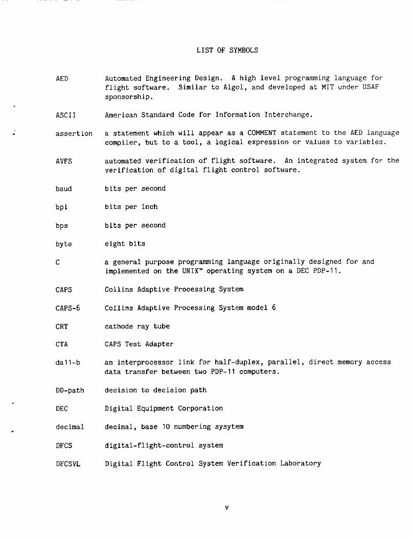
LIST OF SYMBOLS
AED Automated Engineering Design. flight software. sponsorship.
A high level programming language for Similar to Algol, and developed at MIT under USAF
ASCI I American Standard Code for Information Interchange.
c
assertion a statement which will appear as a COMMENT statement to the AED language compiler, but to a tool, a logical expression or values to variables.
AVFS automated verification of flight software. An integrated system f o r the verification of digital flight control software.
baud bits per second
bpi bits per inch
bPS bits per second
byte eight bits
C a general purpose programming language originally designed for and implemented on the UNIX” operating system on a DEC PDP-11.
CAPS Collins Adaptive Processing System
CAPS-6 Collins Adaptive Processing System model 6
CRT cathode ray tube
CTA CAPS Test Adapter
dall-b an interprocessor link for half-duplex, parallel, direct memory access data transfer between two PDP-11 computers.
DD-path decision to decision path
DEC Digital Equipment Corporation
decimal decimal, base 10 numbering sysytem
DFCS digital-flight-control system
DFCSVL Digital Flight Control System Verification Laboratory
V
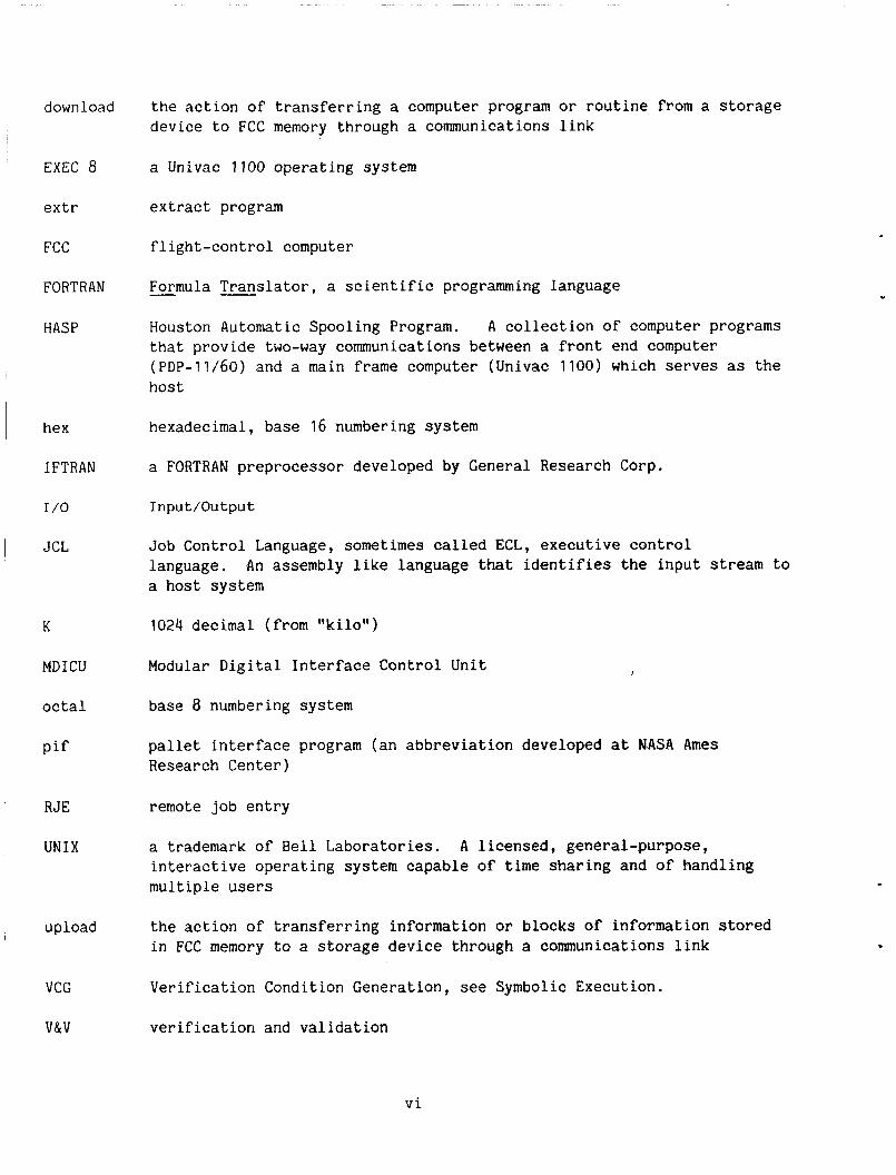
down load
EXEC 8
extr
FCC
FORTRAN
HASP
hex
I FTRAN
I /o
JCL
K
MDICU
octal
pif
R JE
UNIX
upload
VCG
V&V
the action of transferring a computer program or routine from a storage device to FCC memory through a communications link
a Univac 1100 operating system
extract program
flight-control computer
- Formula Translator, a scientific programming language
Houston Automatic Spooling Program. A collection of computer programs that provide two-way communications between a front end computer (PDP-11/60) and a main frame computer (Univac 1100) which serves as the host
hexadecimal, base 16 numbering system
a FORTRAN preprocessor developed by General Research Corp.
Input /Ou tput
Job Control Language, sometimes called ECL, executive control language. a host system
1024 decimal (from "kilo")
Modular Digital Interface Control Unit
base 8 numbering system
pallet interface program (an abbreviation developed at NASA Ames Research Center)
remote job entry
a trademark of Bell Laboratories. A licensed, general-purpose, interactive operating system capable of time sharing and of' handling multiple users
the action of transferring information or blocks of information stored in FCC memory t o a storage device through a communications link
Verification Condition Generation, see Symbolic Execution.
verification and validation
An assembly like language that identifies the input stream t o
vi
SUMMARY
The user's guide of verification and validation (V&V) tools for the Automated- Engineering-Design (AED) language is specifically written to update the information found in several documents pertaining to the automated verification of flight soft- ware tools. The intent of this document is to provide, in one document, all the information necessary to adequately prepare a run to use the AED V&V tools. No attempt is made to discuss the FORTRAN V&V tools since they were not updated and are not currently active. Additionally, this document contains the current descriptions of the AED V&V tools and provides information to augment the NASA TM 84276 entitled "An Integrated User-Oriented Laboratory for Verification of Digital-Flight-Control Systems--Features and Capabilities.''
The AED V&V tools are accessed from the digital-flight-control-systems verifi- cation laboratory (DFCSVL) via a PDP-11/60 digital computer. interface handlers on the PDP-11/60 generate a Univac run stream which is trans- mitted to the Univac via a Remote Job Entry (RJE) link. Job execution takes place on the Univac 1100 and the job output is transmitted back to the DFCSVL and stored as a PDP-11/60 printfile.
The AED V&V tool-
INTRODUCTION
The increased use of digital processors in recent civil and military aircraft's flight control and management systems is forcing a reappraisal of the tools and techniques used for avionic-system design, development and test. A joint NASA/ Federal Aviation Administration (FAA) program on the verification and validation (V&V) of digital-flight-control systems (DFCS) led to the establishment of a veri- fication laboratory at NASA Ames Research Center. The laboratory includes an inte- grated, user oriented environment for tool development and analysis, an initial set of static and dynamic verification tools and a redundant DFCS for use as a test bed. The verification tools are designed to aid the control engineer and avionic system designer in the development and checkout of the flight-control system.
An in-house research project to analyze the effectiveness of the static tools was started and deficiencies in the tools were found. The tools were upgraded to correct these deficiencies before an independent analysis by industry was to be started under NASA contract.
1
I This user's guide revises and upgrades part of a previous document, "Automated Verification of Flight Software--User's Manual" (ref. 1). It will, however, pertain only to the V&V tools specifically designed for the Automated-Engineering-Design (AED) Language, which is the language the digital-flight-control-system software uses in the DFCS verification laboratory (DFCSVL). the FORTRAN V&V tools were excluded from this document because they were not updated after delivery of the tools. engineer" will refer to the same person.
Information and descriptions of
Throughout this document the term "user" and "control
This guide augments the software description of the DFCSVL environment in the NASA TM-84276 entitled ''An Integrated User-Oriented Laboratory for Verification of Digital Flight Control Systems--Features and Capabilities" (ref. 2), provides a description of the tool environment, consolidates the description of each tool, describes the PDP-11/60 commands necessary to get the tools into execution, and lists the constraints associated with the tools. Flow diagrams are provided to help clarify the tool's processing paths. opmental environment and the rehosting requirements necessary for effective and successful hosting onto the target computer. the tool's interface handlers on the PDP-11/60.
Appendices A and B describe the tools' devel-
Appendix C provides a description of
DFCSVL OVERVIEW
The DFCSVL, as seen in figure 1, was established in 1981 at Ames Research The Ames Research Center to perform research experiments related to the DFCS.
Center's studies in fault-tolerant and V&V software tools used a near-term DFCS system in the DFCSVL.
DFCSVL Environment
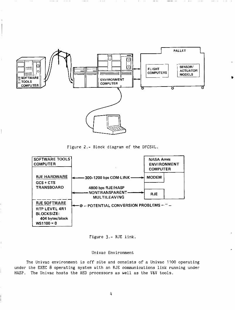
Figure 2 is a block diagram of the functions of the DFCSVL. The DFCSVL includes a PDP-11/60 digital computer (Environment Computer), a palletized DFCS, based on the Collins Adaptive Processing (CAPS) model 6)), a CRT terminal, and a remote computer (Software Tools Computer). computer which is located at the Pacific Missile Test Center facility in Point Mugu, California (referred to as the Point Mugu facility) and accessed via a Remote Job Entry (RJE) communications link between the DFCSVL and Point Mugu.
The V&V tools are hosted on the Univac
Environment Computer- The "environment computer" is a PDP-11/60 digital com- puter with 256K words of memory, two disk drives with a storage capacity of 52 Mbytes, one 1600 bpi density tape drive, one 600-line/min line printer, and three CRT terminals connected to the system. For further details refer to section 5 of reference 2.
Remote Link- The Univac 1100 is connected to the PDP-11/60 through a RJE communications (dataphone) link or a standard dataphone link as seen in figure 3.
2
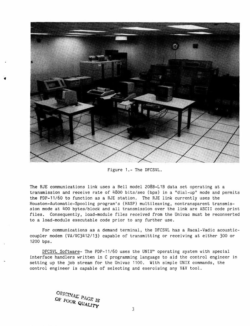
Figure 1.- The DFCSVL.
The RJE communications link uses a Bell model 208B-L1B data set operating at a transmission and receive rate of 4800 bits/sec (bps) in a "dial-up" mode and permits the PDP-11/60 to function as a RJE station. Houston-Automatic-Spooling program's (HASP) multileaving, nontransparent transmis- sion mode at 400 bytes/block and all transmission over the link are ASCII code print files. Consequently, load-module files received from the Univac must be reconverted to a load-module executable code prior to any further use.
The RJE link currently uses the
For communications as a demand terminal, the DFCSVL has a Racal-Vadic acoustic- coupler modem (VA/VC3412/13) capable of transmitting o r receiving at either 300 or 1200 bps .
DFCSVL Software- The PDP-11/60 uses the UNIX" operating system with special interface handlers written in C programming language to aid the control engineer in setting up the job stream for the Univac 1100. With simple UNIX commands, the control engineer is capable of selecting and exercising any V&V tool.
3
SOFTWARE TOOLS COMPUTER
-300-1200 bps COM-LINK b
4800 bps RJE/HASP -NONTRANSPARENT *
MU LTI LE AV I NG
Figure 2.- Block diagram of the DFCSVL.
NASA Ames ENVIRONMENT COMPUTER
MODEM
RJE
RJE HARDWARE GCS + CTS TRANSBOARD
_-_-_--- RJE SOFTWARE RTP LEVEL 4R1 BLOC KS I2 E :
WSllOO = 0 404 bytedblock
Figure 3 . - RJE link.
Univac Environment
The Univac environment is off site and consists of a Univac 1100 operating under the EXEC 8 operating system with an RJE communications link running under HASP. The Univac hosts the AED processors as well as the V&V tools.
4
Requirements for the off-site Univac are:
1. Hardware a. Univac 1100/63 computer b. Tape units; 1600-bpi and 6250-bpi capabilities c. Disk units; mass-storage medium
2. Software a. EXEC 8 level 38R5A operating system b. AED processors; CAPS cross compiler
CAPS cross assembler AED link editor tape transmission program
(These processors execute under the EXEC 8 system and were originally developed and executed under a Univac 1100 using the EXEC 8 operating system. )
c. Software V&V tools reside and execute on the Univac 1100
The system will receive and return batch jobs across the RJE link which originates at Ames Research Center. The system will also provide the hardware and computer time to execute AED and FORTRAN IV programs.
TEST I NG
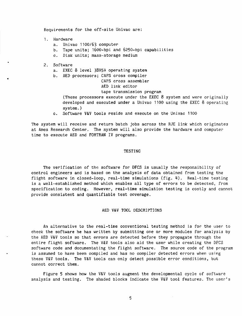
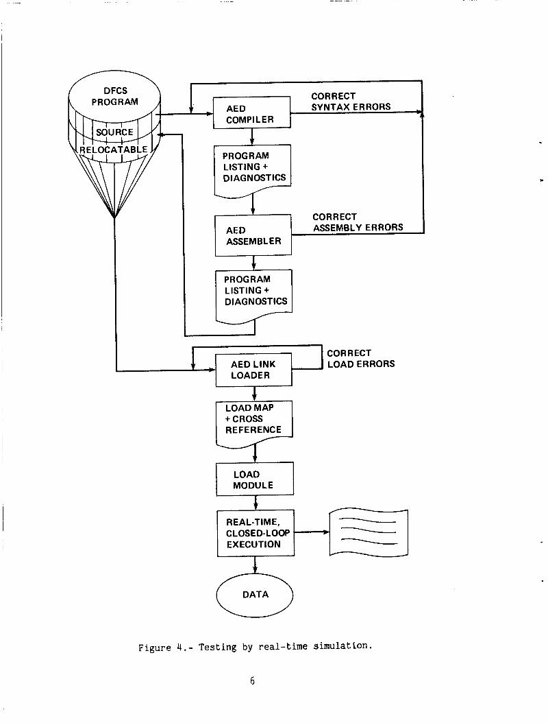
The verification of the software for DFCS is usually the responsibility of control engineers and is based on the analysis of data obtained from testing the flight software in closed-loop, real-time simulations (fig. 4). Real-time testing is a well-established method which enables all type of errors to be detected, from specification to coding. However, real-time simulation testing is costly and cannot provide consistent and quantifiable test coverage.
AED V&V TOOL DESCRIPTIONS
An alternative to the real-time conventional testing method is for the user to check the software he has written by submitting one or more modules for analysis by the AED V&V tools so that errors are detected before they propagate through the entire flight software. The V&V tools also aid the user while creating the DFCS software code and documentating the flight software. The source code of the program is assumed to have been compiled and has no compiler detected errors when using these V&V tools. The V&V tools can only detect possible error conditions, but cannot correct them.
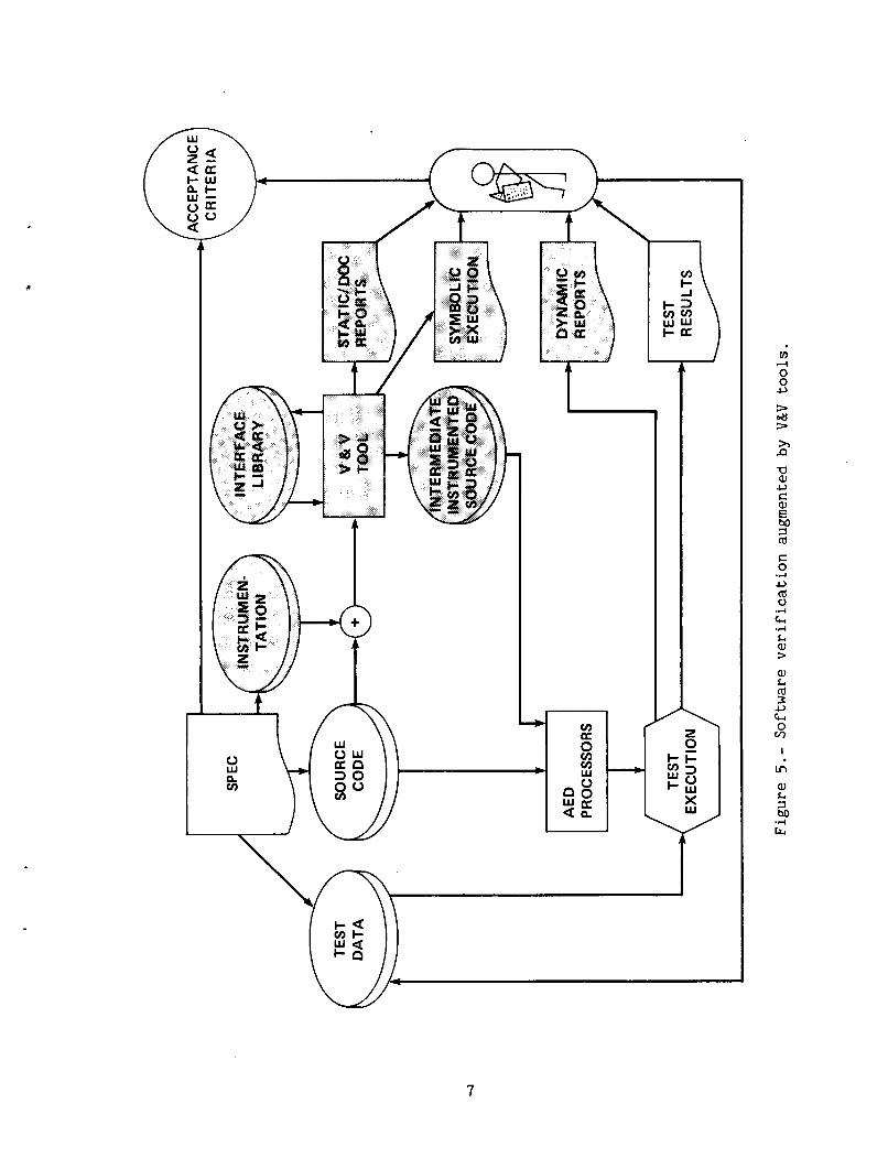
Figure 5 shows how the V&V tools augment the developmental cycle of software analysis and testing. The shaded blocks indicate the V&V tool features. The user's
5
CORRECT t * AED SYNTAX ERRORS
COMPl L ER B
RELOCATABLE
REAL-TIME, CLOSED- LOOP EXECUTION
t CORRECT AED ASSEMBLY ERRORS ASSEMBLER
\ * \ -
LISTING +
LISTING + DIAGNOSTICS
1 4 AEDLINK 1 ILOADERRORS LOADER
c
Figure 4.- Testing by real-time simulation.
6
J
t / f
\
7
source code is analyzed by the static V&V tools to assist in finding inconsistencies in the use of the variables and in the structure of a program, and produces a static analysis or documentation report. Assertions, which are logical statements yielding either a true or false condition, can be added to the source text to further detect static or dynamic errors. An assertion statement is interpreted by the AED compiler as just another comment statement.
The AED dynamic tools automatically insert probes at appropriate points in a module to determine testing coverage, to insert assertions into a module to check on assertion violations, or to trace variables in the code. During dynamic test, these probes record data which are used to report execution coverage, assertion viola- tions, execution time, and the values of important variables. The data recorded are stored in CAPS memory for later analysis by the report generator on the PDP-11/60. This information is used with other tests to indicate the focus of retesting which is discussed in more detail under "Symbolic Execution.tt
The tools are used to perform formal verification of formulas and assertions via symbolic execution. input. The procedure for formal verification is to execute the program "symboli- cally"; that is to use symbols as input data rather than specific numbers. The program is verified or "proven" correct for a wider range of its variables than is practical to assign during the execution test.
When a program is executed, numerical data is supplied as
During the analysis by the static INTERFACE tool, an interface library is created and maintained as shown in figure 5. This interface-library file is the key to multiple module interface checks. changes in interface properties; e.g., addition or deletion of parameters, changes in the type or use of parameters, changes to COMMON, and changes to invocations.
The INTERFACE tool analyzes each module for
The following sections contain more complete details of the full power of the AED V&V tools and how to use them.
Static Tools
Static Tools encompass the static analysis tools and the tools designed specif- The reason for this grouping is consistency with ically for documentation purposes.
the UNIX command. When the tool is documentation type, the tool is identified as such.
Static analysis tools are designed to uncover inconsistencies in the use of variables and in the structure of the module. An inconsistency indicates the exis- tence of an error or the possibility of an error.
Static analysis tools perform: set and use checking, loop checking, type checking, path checking, interface checking, and input/output (I/O) checking. Detailed descriptions and sample outputs are shown as each tool is discussed in this section. static tools.
The general format presented here is of the UNIX command to exercise the
8
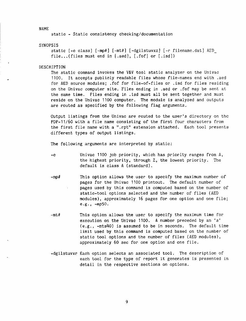
NAME static - Static consistency checking/documentation
SYNOPSIS static [-c class] [-mpC] [-mtb] [-dgilstuvxz] [-r filename.dat1 AED- file ...( files must end in [.aed], [.fof] or [.isd])
DESCRIPTION The static command invokes the V&V tool static analyzer on the Univac 1100. It accepts publicly readable files whose file-names end with .aed for AED source modules; .fof for file-of-files or .isd for files residing on the Univac computer site. Files ending in .aed o r .fof may be sent at the same time. Files ending in .isd must all be sent together and must reside on the Univac 1100 computer. The module is analyzed and outputs are routed as specified by the following flag arguments.
Output listings from the Univac are routed to the user's directory on the PDP-11/60 with a file name consisting of the first four characters from the first file name with a ".rpt" extension attached. Each tool presents different types of output listings.
The following arguments are interpreted by static:
-C Univac 1100 job priority, which has priority ranges from A, the highest priority, through Z, the lowest priority. The default is class A (standard).
-mp#
-mtb
This option allows the user to specify the maximum number of pages for the Univac 1100 printout. The default number of pages used by this command is computed based on the number of static-tool options selected and the number of files (AED modules), approximately 16 pages for one option and one file; e.g., -mp50.
This option allows the user to specify the maximum time for execution on the Univac 1100. A number preceded by an ' s ' (e.g., -mts40) is assumed to be in seconds. The default time limit used by this command is computed based on the number of static tool options and the number of files (AED modules), approximately 60 sec for one option and one file.
-dgilstuvxr Each option selects an associated tool. The description of each tool for the type of report it generates is presented in detail in the respective sections on options.
9
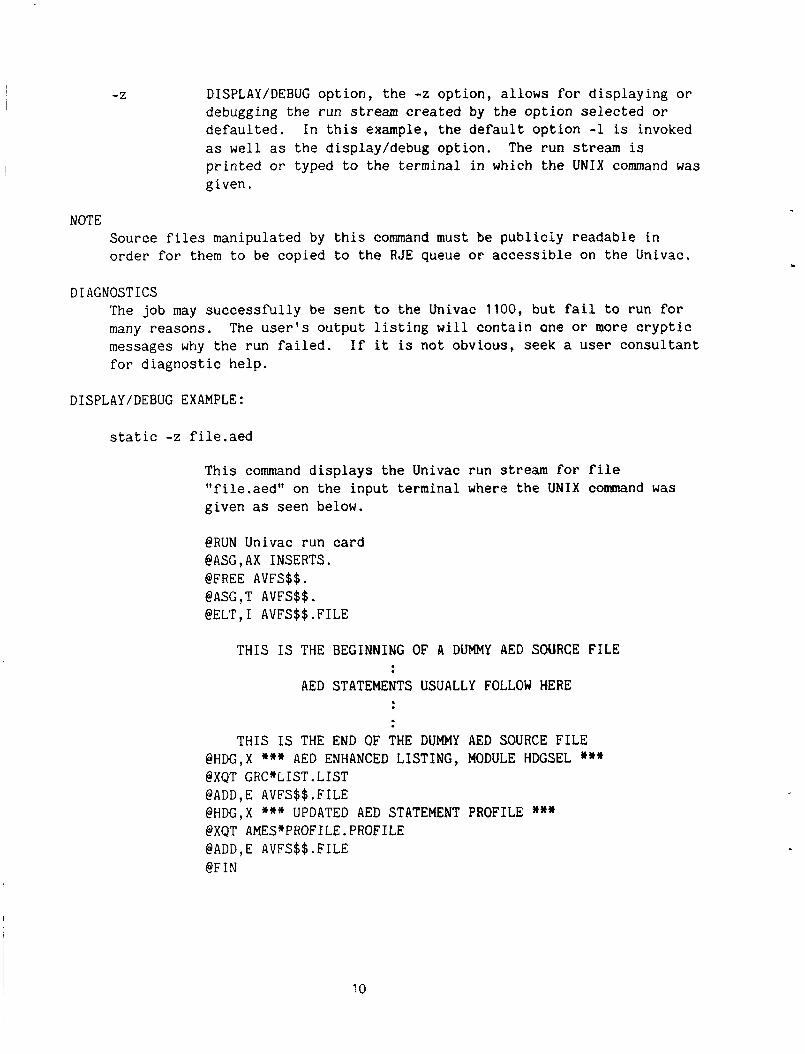
DISPLAY/DEBUG option, the -2 option, allows for displaying or debugging the run stream created by the option selected or defaulted. In this example, the default option -1 is invoked as well as the display/debug option. The run stream is printed or typed to the terminal in which the UNIX command was given.
NOTE Source files manipulated by this command must be publicly readable in order for them to be copied to the RJE queue or accessible on the Univac.
DIAGNOSTICS The job may successfully be sent to the Univac 1100, but fail to run for many reasons, messages why the run failed. If it is not obvious, seek a user consultant for diagnostic help.
The user's output listing will contain one or mQre cryptic
DISPLAY/DEBUG EXAMPLE:
static -z file.aed
This command displays the Univac run stream for file "file.aed" on the input terminal where the UNIX command was given as seen below.
@RUN Univac run card @ASG,AX INSERTS. @FREE AVFS$$. @ASG ,T AVFS$$ . @ELT,I AVFS$$.FILE
THIS IS THE BEGINNING OF A DUMMY AED SOURCE FILE
AED STATEMENTS USUALLY FOLLOW MERE
THIS IS THE END OF THE DUMMY AED SOURCE FILE @HDG,X *** AED ENHANCED LISTING, MODULE HDGSEL *** @XQT GRC*LIST.LIST @ADD,E AVFS$$.FILE @HDG,X *** UPDATED AED STATEMENT PROFILE *** @XQT AMES*PROFILE.PROFILE @ADD, E AVFS$$ . FILE @FIN
10
I +
4
L
-d option: MODULE DEPENDENCIES.- UNIX COMMAND EXAMPLE:
static -d alatcom.aed
This command generates a module-dependency report for the AED module alatcom.
UNIVAC COMMAND EXAMPLE:
@XQT AMES*DEPEND.DEPEND @ADD,E AVFS$$.filename
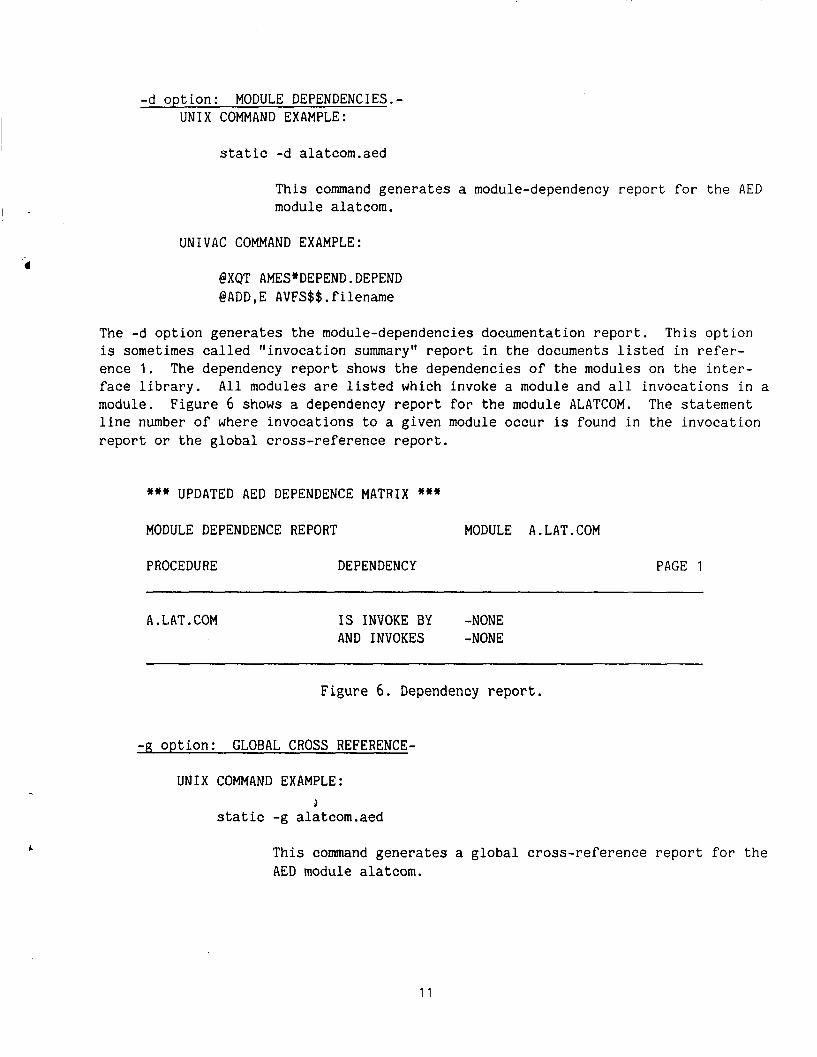
The -d option generates the module-dependencies documentation report. This option is sometimes called "invocation summary" report in the documents listed in refer- ence 1. The dependency report shows the dependencies of the modules on the inter- face library. All modules are listed which invoke a module and all invocations in a module. The statement line number of where invocations to a given module occur is found in the invocation report or the global cross-reference report.
Figure 6 shows a dependency report for the module ALATCOM.
*** UPDATED AED DEPENDENCE MATRIX ***
MODULE DEPENDENCE REPORT MODULE A.LAT.COM
PROCEDURE DEPENDENCY PAGE 1
A. L AT. COM IS INVOKE BY -NONE AND INVOKES -NONE
Figure 6. Dependency report.
-g option: GLOBAL CROSS REFERENCE-
UNIX COMMAND EXAMPLE: i
static -g alatcom.aed
This command generates a global cross-reference report for the AED module alatcom.
1 1
I UNIVAC COMMAND EXAMPLE:
@XQT AMES*GBLXREF.INITIAL @XQT AMES*GBLXREF.GLOBAL @ADD,E AVFS$$.filenarne @XQT AMES*GBLXREF.FINAL
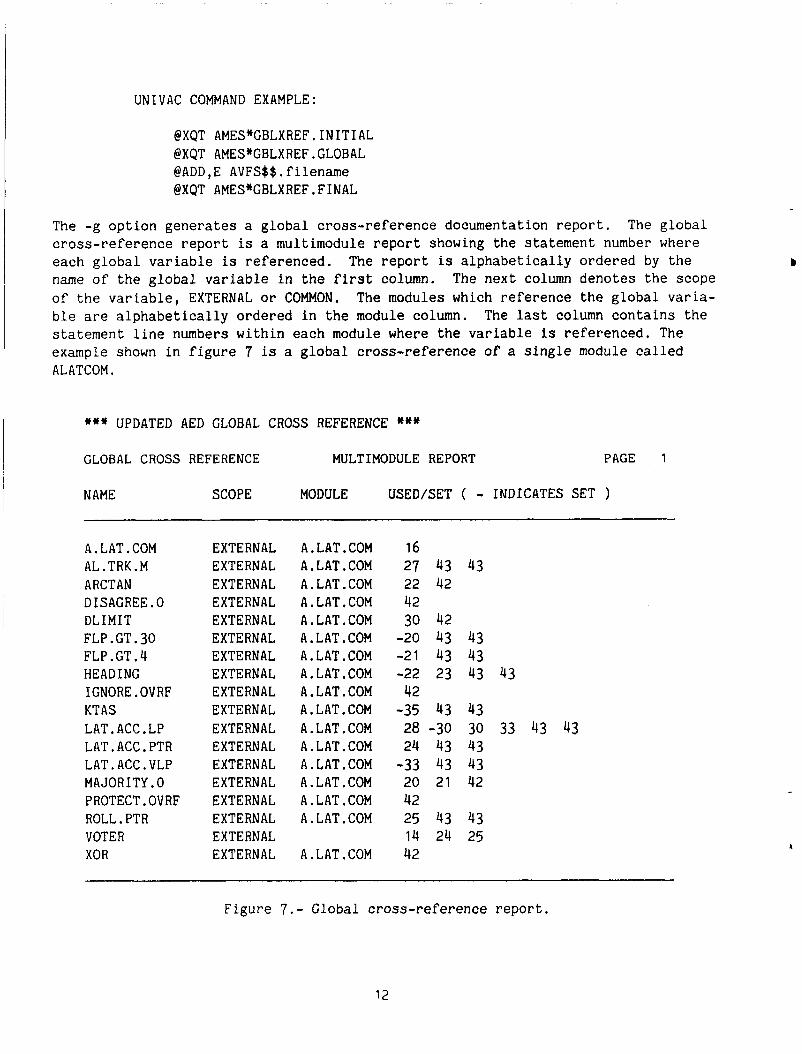
The -g option generates a global cross-reference documentation report. cross-reference report is a multimodule report showing the statement number where each global variable is referenced. The report is alphabetically ordered by the name of the global variable in the first column. of the variable, EXTERNAL or COMMON. ble are alphabetically ordered in the module column. statement line numbers within each module where the variable is referenced. The example shown in figure 7 is a global cross-reference of a single module called ALATCOM.
The global
The next column denotes the scope The modules which reference the global varia-
The last column contains the
*** UPDATED AED GLOBAL CROSS REFERENCE *** GLOBAL CROSS REFERENCE MULTIMODULE REPORT PAGE 1
NAME SCOPE MODULE USED/SET ( - INDICATES SET )
A. LAT . COM AL. TRK. M ARCTAN DISAGREE.0 DLIMIT FLP . GT. 30 FLP . GT .4 HEADING 1GNORE.OVRF KT AS LAT.ACC.LP LAT.ACC.PTR LAT.ACC.VLP MAJORITY.0 PROTECT.OVRF ROLL. PTR VOTER XOR
EXTERNAL EXTERNAL EXTERNAL EXTERNAL EXTERNAL E XT E RNA L EXTERNAL EXTERNAL EXTERNAL EXTERNAL EXTERNAL EXTERNAL EXTERNAL EXTERNAL EXTERNAL EXTERNAL EXTERNAL EXTERNAL
A. LAT .COM A. LAT . COM A. LAT. COM A. LAT. COM A. LAT .COM A, LAT . COM A. LAT . COM A. LAT . COM A. LAT . COM A, LAT. COM A. LAT . COM A. LAT. COM A. LAT . COM A. LAT .COM A. LAT . COM A. LAT. COM
A. LAT . COM
16 27 43 43 22 42 42 30 42 -20 43 43 -21 43 43 -22 23 43 43
-35 43 43 28 -30 30 33 43 43 24 43 43 -33 43 43 20 21 42 42 25 43 43 14 24 25 42
42
Figure 7.- Global cross-reference report.
12
-i option: INTERFACE-
-
UNIX COMMAND EXAMPLE:
s t a t i c -i aforexec.aed
T h i s command generates an interface analysis report for the AED module aforexec.
UNIVAC COMMAND EXAMPLE:
@XQT AMES*INTER.INTER @ A D D , E AVFS$$.filename
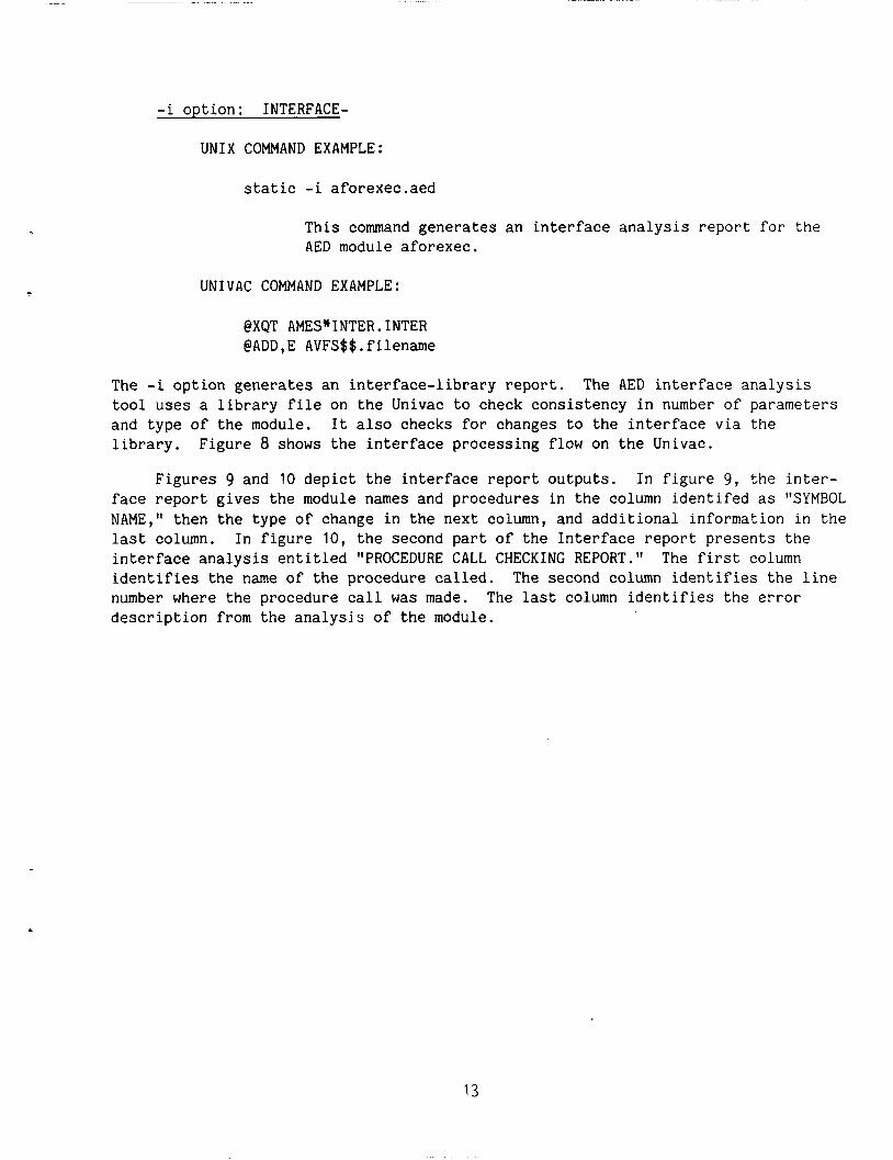
The -i option generates an interface-library report. tool uses a l ibrary f i l e on the Univac to check consistency i n number of parameters and type of the module. l ibrary.
The AED interface analysis
I t a l so checks for changes to the interface via the Figure 8 shows t h e interface processing flow on the Univac.
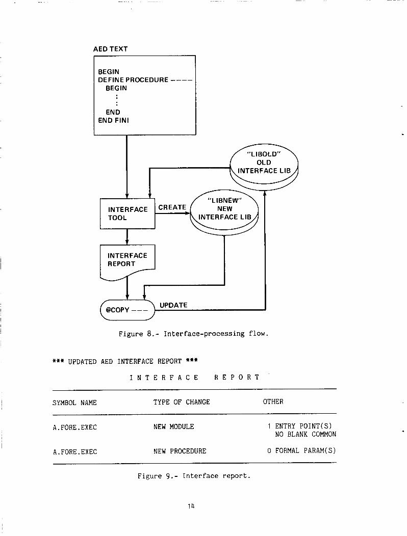
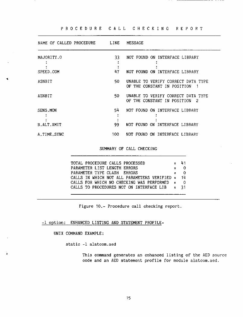
Figures 9 and 10 depict the interface report outputs. In figure 9 , the inter- face report gives the module names and procedures i n the column identifed as "SYMBOL NAME," then the type of change i n the next column, and additional information i n the l a s t column. In figure 10, the second part of the Interface report presents the interface analysis en t i t l ed "PROCEDURE CALL CHECKING REPORT.'' The f i r s t column ident i f ies the name of the procedure called. number where the procedure c a l l was made. The l a s t column ident i f ies the error description from the analysis of the module.
The second column ident i f ies the l i n e
AED TEXT
BEGIN DEFINE PROCEDURE ----
BEG I N
END END FIN1
INTERFACE LIB
INTERFACE CREAT TOOL INTERFACE LIB
i
Figure 8.- Interface-processing flow.
*** UPDATED AED INTERFACE REPORT *** I N T E R F A C E R E P O R T
SYMBOL NAME TYPE OF CHANGE OTHER ~~ ~
A.FORE.EXEC
A.FORE.EXEC
NEW MODULE
NEW PROCEDURE
1 ENTRY POINT(S) NO BLANK COMMON
0 FORMAL PARAM(S)
Figure 9.- Interface report.
14
P R O C E D U R E C A L L C H E C K I N G R E P O R T
I
NAME OF CALLED PROCEDURE LINE MESSAGE
MAJORITY.0
SPEED. COM
ASNB I T
ASNB IT
SENS . MON
B.ALT.XMIT
33 NOT FOUND ON INTERFACE LIBRARY
47 NOT FOUND ON INTERFACE LIBRARY
50 UNABLE TO VERIFY CORRECT DATA TYPE OF THE CONSTANT IN POSITION 1
50 UNABLE TO VERIFY CORRECT DATA TYPE OF THE CONSTANT IN POSITION 2
54 NOT FOUND ON INTERFACE LIBRARY
99 NOT FOUND ON INTERFACE LIBRARY
A.TIME.SYNC 100 NOT FOUND ON INTERFACE LIBRARY
SUMMARY OF CALL CHECKING
TOTAL PROCEDURE CALLS PROCESSED = 41 PARAMETER LIST LENGTH ERRORS = o PARAMETER TYPE CLASH ERRORS = o CALLS IN WHICH NOT ALL PARAMETERS VERIFIED = 14 CALLS FOR WHICH NO CHECKING WAS PERFORMED = 0 CALLS TO PROCEDURES NOT ON INTERFACE LIB = 31
Figure 10.- Procedure call checking report.
-1 option: ENHANCED LISTING AND STATEMENT PROFILE-
UNIX COMMAND EXAMPLE:
static -1 alatcom.aed
This command generates an enhanced listing of the AED source code and an AED statement profile for module alatcom.aed.
15
UNIVAC COMMAND EXAMPLE:
@XQT GRC*LIST.LIST @ADD,E AVFS$$.filename @XQT AMES*PROFILE.PROFILE @ADD,E AVFS$$.filename
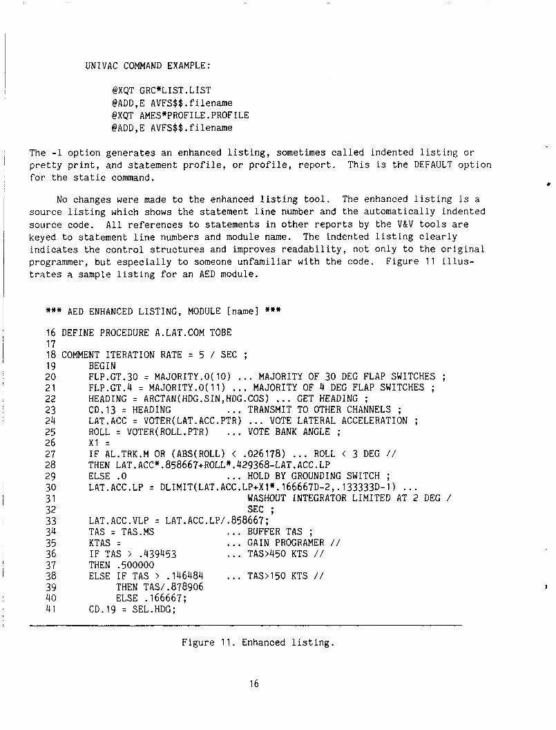
The -1 option generates an enhanced listing, sometimes called indented listing or pretty print, and statement profile, o r profile, report. This is the DEFAULT option for the static command.
c
No changes were made to the enhanced listing tool. The enhanced listing is a source listing which shows the statement line number and the automatically indented source code. All references to statements in other reports by the V&V tools are keyed to statement line numbers and module name. indicates the control structures and improves readability, not only to the original programmer, but especially to someone unfamiliar with the code. Figure 1 1 illus- trates a sample listing for an AED module.
The indented listing clearly
*** AED ENHANCED LISTING, MODULE [name] *** 16 DEFINE PROCEDURE A.LAT.COM TOBE 17 18 COMMENT ITERATION RATE = 5 / SEC ; 19 BEGIN 20 FLP.GT.30 = MAJORITY.O(l0) ... MAJORITY OF 30 DEG FLAP SWITCHES ; 21 FLP.CT.4 = MAJORITY.O(l1) ... MAJORITY OF 4 DEG FLAP SWITCHES ; 22 HEADING = ARCTAN(HDG.SIN,HDC.COS) ... GET HEADING ; 24 LAT.ACC = VOTER(LAT.ACC.PTR) ... VOTE LATERAL ACCELERATION ; 25 ROLL = VOTER(ROLL.PTR) ... VOTE BANK ANGLE ; 26 Xl =
28 27 29 ELSE .O ... HOLD BY GROUNDING SWITCH ; 31 WASHOUT INTEGRATOR LIMITED AT 2 DEG / 32 SEC ; 33 LAT.ACC.VLP = LAT.ACC.LP/.858667; 34 TAS = TAS.MS . .. BUFFER TAS ; 35 KTAS = ... GAIN PROGRAMER / / 36 IF TAS > .439453 ... TAS>450 KTS / / 37 THEN .500000 38 ELSE IF TAS > .146484 . . . TAS>150 KTS / / 39 THEN TAS/ .878906 40 ELSE .166667; 4 i CD.19 = SEL.HDG;
23 CD.13 = HEADING ... TRANSMIT TO OTHER CHANNELS ;
IF AL.TRK.M OR (ABS(R0LL) < .026178) ... ROLL < 3 DEG / / THEN LAT . ACC* .858667+ROLL*. 429368-LAT. ACC . LP
30 LAT. ACC . LP = DLIMIT( LAT . ACC. LP+X 1 * .166667D-2, .133333D- 1 ) . . .
I
Figure 11. Enhanced listing.
16
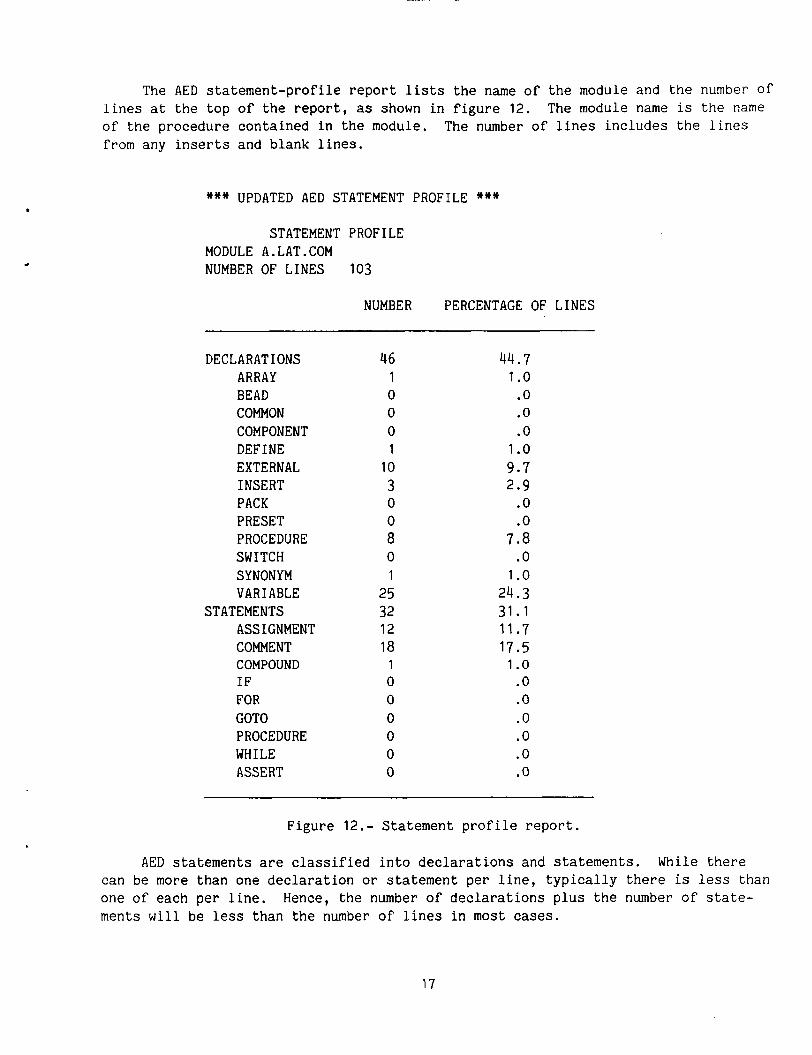
The AED statement-profile report lists the name of the module and the number of lines at the top of the report, as shown in figure 12. The module name is the name of the procedure contained in the module. The number of lines includes the lines from any inserts and blank lines.
*** UPDATED AED STATEMENT PROFILE ***
STATEMENT PROFILE MODULE A.LAT.COM NUMBER OF LINES 103
NUMBER PERCENTAGE OF LINES
DECLARATIONS ARRAY BEAD COMMON COMPONENT DEFINE EXTERNAL INSERT PACK PRESET PROCEDURE SWITCH SYNONYM VARIABLE
ASSIGNMENT COMMENT COMPOUND IF FOR GOT0 PROCEDURE WHILE ASSERT
STATEMENTS
46 1 0 0 0 1
10 3 0 0 8 0 1
25 32 12 18
1 0 0 0 0 0 0
44.7 1 .o .o .o .o
1 .o 9.7 2.9
.o
.o 7.8
.o 1 .o
24.3 31.1 11.7 17.5
1 .o .o .o .o .o .o .o
Figure 12.- Statement profile report.
AED statements are classified into declarations and statements. While there can be more than one declaration or statement per line, typically there is less than one of each per line. ments will be less than the number of lines in most cases.
Hence, the number of declarations plus the number of state-
17
Under declarations, there are declarations for arrays, beads, common, compo- nents, defines, externals, packs, presets, procedures, switches, synonyms, and variables. Each of these is counted separately. Inserts are listed under declara- tions, but are not included in the count for declarations. In AED, the inserts normally contain declarations. The line percentage is computed on the basis of the total number of lines printed on top of the profile report.
Under statements, there are statements for assignment, compound, if, for, goto, procedure, and while categories, A line can contain several categories. For exam- ple, a statement consisting of a BEGIN ... END construct is counted as a compound statement. Another example of a statement containing several categories is the IF statement. It usually contains a BEGIN. ..END compound statement as well as a proce- dure invocation. Comments and assertions categories are listed under statements and are counted separately.
i
-s option: SYMBOLS (SET/USE).-
UNIX COMMAND EXAMPLE:
static -s alatcom.aed
This command generates a SET/USE listing for module alatcom.aed.
UNIVAC COMMAND EXAMPLE:
@XQT AMES*SETUSE.SETUSE @ADD,E AVFS$$.filename
I The -s option generates a symbols report, also called SET/USE. of an AED source module for SET/USE checking analyzes the variables used before they are set to a value, or set and not used. When 1/0 assertions are added t o the source module, a complete static analysis check is made with the SETNSE tool.
The static analysis 1
Input/Output assertions are used in a static analysis to check for consistency between the intended use of a variable and the actual use of a variable. Variables which provide input data to a module should be asserted with an input assertion.
An input assertion has the form:
COMMENT INPUT* <type> <variable>;
An example of an input assertion is
COMMENT INPUT* REAL HEIGHT;
where the variable named HEIGHT is an input t o the module.
18
Variables which provide output data from a module should be asserted with an output assertion. An output assertion has the form
COMMENT OUTPUT* <type> <variable>;
Variables which are used both as input and as output should have both assertions.
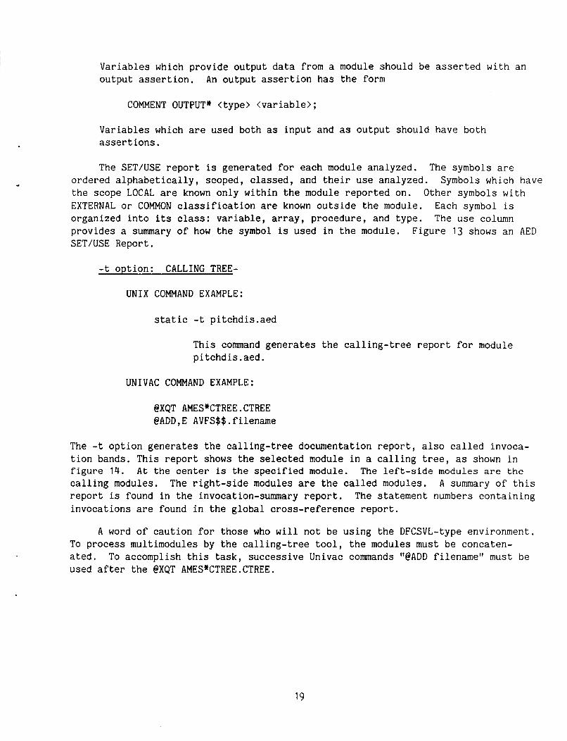
The SET/USE report is generated for each module analyzed. The symbols are ordered alphabetically, scoped, classed, and their use analyzed. Symbols which have the scope LOCAL are known only within the module reported on. Other symbols with EXTERNAL or COMMON classification are known outside the module. Each symbol is organized into its class: variable, array, procedure, and type. The use column provides a summary of how the symbol is used in the module. Figure 13 shows an AED SET/USE Report.
-t option: CALLING TREE-
UNIX COMMAND EXAMPLE:
static -t pitchdis.aed
This command generates the calling-tree report for module pitchdis.aed.
UNIVAC COMMAND EXAMPLE:
@XQT AMES*CTREE.CTREE @ADD,E AVFS$$.filename
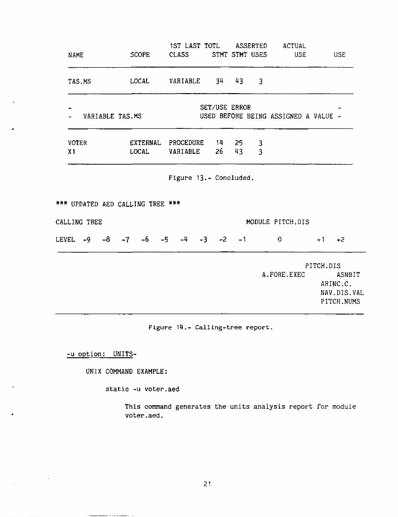
The -t option generates the calling-tree documentation report, also called invoca- tion bands. This report shows the selected module in a calling tree, as shown in figure 14. At the center is the specified module. The left-side modules are t h e calling modules. A summary of this report is found in the invocation-summary report. The statement numbers containing invocations are found in the global cross-reference report.
The right-side modules are the called modules.
A word of caution for those who will not be using the DFCSVL-type environment. To process multimodules by the calling-tree tool, the modules must be concaten- ated. To accomplish this task, successive Univac commands "@ADD filename" must be used after the @XQT AMES*CTREE.CTREE.
19
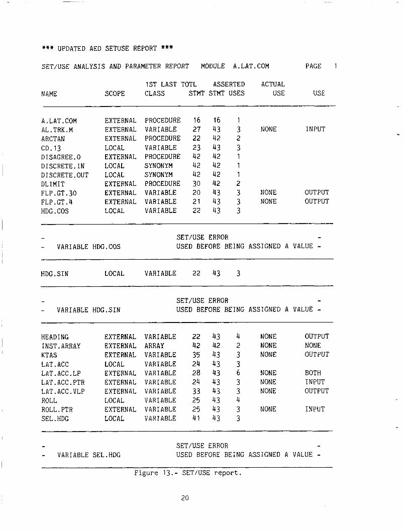
*** UPDATED AED SETUSE REPORT *** SET/USE ANALYSIS AND PARAMETER REPORT MODULE A.LAT.COM PAGE 1
1ST LAST TOTL ASSERTED ACTUAL NAME SCOPE CLASS STMT STMT USES USE USE
A. LAT .COM AL . TRK. M ARCTAN CD. 13 DISAGREE.0 DISCRETE.IN DISCRETE.OUT DLIMIT FLP . GT. 30 FLP . GT .4 HDG .COS
EXTERNAL EXTERNAL EXTERNAL LOCAL EXTERNAL LOCAL LOCAL EXTERNAL EXTERNAL EXTERNAL LOCAL
PROCEDURE VARIABLE PROCEDURE VARIABLE PROCEDURE SYNONYM SYNONYM PROCEDURE VARIABLE VARIABLE VARIABLE
16 16 1 27 43 3 NONE INPUT 22 42 2 23 43 3 42 42 1 42 42 1 42 42 1 30 42 2 20 43 3 NONE OUTPUT 21 43 3 NONE OUTPUT 22 43 3
- - VARIABLE HDG.COS
SET/USE ERROR - USED BEFORE BEING ASSIGNED A VALUE -
~~ ~
HDG . SIN LOCAL VARIABLE 22 43 3
- - VARIABLE HDG.SIN
SET/USE ERROR - USED BEFORE BEING ASSIGNED A VALUE -
HEADING 1NST.ARRAY KT AS LAT. ACC LAT.ACC.LP LAT.ACC.PTR LAT.ACC.VLP ROLL ROLL. PTR SEL. HDG
EXTERNAL EXTERNAL EXTERNAL LOCAL EXTERNAL EXTERNAL EXTERNAL LOCAL EXTERNAL LOCAL
VARIABLE ARRAY VARIABLE VARIABLE VARIABLE VARIABLE VARIABLE VARIABLE VARIABLE VARIABLE
22 42 35 24 28 24 33 25 25 41
43 4 NONE OUTPUT 42 2 NONE NONE 43 3 NONE OUTPUT
43 6 NONE BOTH 43 3 NONE INPUT 43 3 NONE OUTPUT
43 3 NONE INPUT
43 3
43 4
43 3
- - VARIABLE SEL.HDG
SET/USE ERROR - USED BEFORE BEING ASSIGNED A VALUE -
Figure 13.- SET/USE report .
20
NAME 1ST LAST TOTL ASSERTED ACTUAL
SCOPE CLASS STMT STMT USES USE USE
TAS . MS LOCAL VARIABLE 34 43 3
- - VARIABLE TAS.MS
SETNSE ERROR - USED BEFORE BEING ASSIGNED A VALUE -
VOTER x1
EXTERNAL PROCEDURE 14 25 3 LOCAL VARIABLE 26 43 3
Figure 13.- Concluded.
*** UPDATED AED CALLING TREE *** CALLING TREE MODULE PITCH.DIS
LEVEL -9 -a -7 -6 -5 -4 -3 -2 -1 0 +1 +2
PITCH.DIS A.FORE.EXEC ASNB IT
AR1NC.C. NAV.DIS.VAL PITCH.NUMS
Figure 14.- Calling-tree report.
-u option: UNITS-
UNIX COMMAND EXAMPLE:
static -u voter.aed
This command generates the units analysis report fo r module voter.aed.
21
UNIVAC COMMAND EXAMPLE:
@XQT AMES*UNITS.UNITS @ADD,E AVFS$$.filenarne
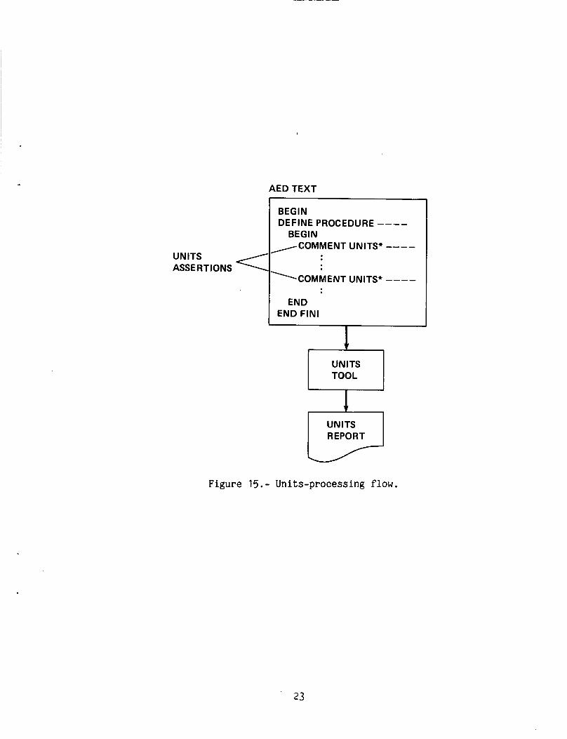
The -u option generates the units analysis report. into a program so consistency checks are made on the use of units. for which units are specified has units declared in the form
Units assertions are inserted Each variable
COMMENT UNITS* <variable> = <units expression>;
For example, t o state that the variable named SPEED has units of FEET/SEC, and TIME has units of SEC, type in
I COMMENT UNITS* SPEED = FEET/SEC; COMMENT UNITS* TIME = SEC;
To state that the variable named DIST has units of METER,
COMMENT UNITS* DIST = METER;
The units analyzer ensures the operations on the variable
type in
, which hav if ied units, is done in a consistent manner. That is, if an assignment was made such as
SPEED = DIST * TIME; the units analyzer would report a units error of the form:
*****UNITS ERROR***** FEET/SEC=METER*SEC
Units are combined symbolically across multiplication and division to form new units. Checks are made across addition, subtraction, and assignment operations to ensure units consistency. tool. Currently the tool is incapable of handling embedded operations such as an argument in the calling list of a procedure, or embedded by parentheses.
Figure 15 shows the flow diagram for processing the units
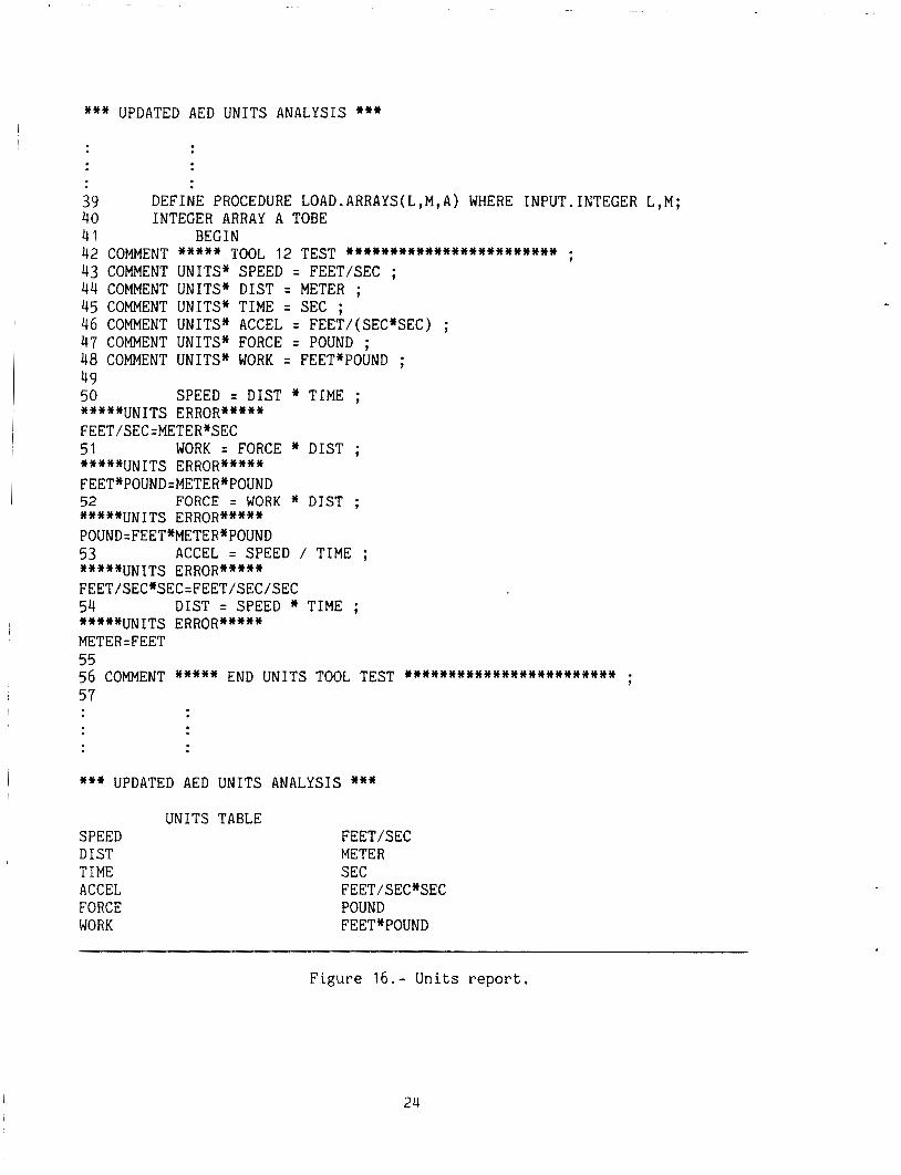
After the units analysis is complete, the units for each variable is listed in the units table.
Figure 16 shows units specified for speed, distance, time, acceleration, force, and work. The error messages are displayed in the source code listing when incon- sistent units occur during analysis. The units table summarizing the units asser- tions, follows the source-code listing.
22
AED TEXT
UNITS ASSE R T I ONS
BEGIN DEFINE PROCEDURE ----
BEGIN COMMENT UNITS* ----
~ C O M M E N T UNITS* ----
END FIN1 k-- UNITS REPORT
Figure 15.- Units-processing flow.
23
*** UPDATED AED UNITS ANALYSIS ***
39 DEFINE PROCEDURE LOAD.ARRAYS(L,M,A) WHERE INPUT. INTEGER L,M; 40 INTEGER ARRAY A TOBE 41 BEG IN 42 COMMENT +*+** TOOL 12 TEST +~+w**+c+*+*++*Y*++++,*+ ; 43 COMMENT UNITS* SPEED = FEET/SEC ; 44 COMMENT UNITS* DIST = METER ; 45 COMMENT UNITS* TIME = SEC ; 46 COMMENT UNITS* ACCEL = FEET/(SEC*SEC) ; 47 COMMENT UNITS* FORCE = POUND ; 48 COMMENT UNITS* WORK = FEET*POUND ; 49 50 SPEED = DIST * TIME ; *****UNITS ERROR***** FEET/SEC=METER*SEC 51 WORK = FORCE * DIST ; *****UNITS ERROR***** FEET*POUND=METER*POUND 52 FORCE = WORK * DIST ; *****UNITS ERROR*****
53 ACCEL = SPEED / TIME ; *****UNITS ERROR***** FEET/SEC*SEC=FEET/SEC/SEC 54 DIST = SPEED * TIME ; *****UNITS ERROR***** METER=FEET 55
57
POUND=FEET*METER*P~UND
56 COMMENT ***** END UNITS TOOL TEST . . . . . . . . . . . . . . . . . . . . . . . . ;
*** UPDATED AED UNITS ANALYSIS *** UNITS TABLE
SPEED DIST TIME ACCEL FORCE WORK
FEET/SEC METER SEC
POUND FEET*POUND
FEET/SEC*SEC
Figure 16.- Units repor t .
24
-v option: INVOCATIONS-
UNIX COMMAND EXAMPLE:
static -v aforeinit.aed
This command generates the INVOCATION-documentation report for module aforeinit.aed
UNIVAC COMMAND EXAMPLE:
@XQT AMES*INVOKE.INVOKE @ADD,E AVFS$$.filename
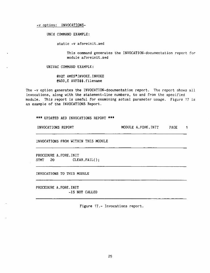
The -v option generates the INVOCATION-documentation report. The report shows all invocations, along with the statement-line numbers, to and from the specified module. This report is useful for examining actual parameter usage. Figure 17 is an example of the INVOCATIONS Report.
*** UPDATED AED INVOCATIONS REPORT *** INVOCATIONS REPORT MODULE A.FORE.INIT PAGE 1
INVOCATIONS FROM WITHIN THIS MODULE
PROCEDURE A.FORE.INIT STMT 20 CLEAR.FAIL0;
INVOCATIONS TO THIS MODULE
PROCEDURE A.FORE.INIT -IS NOT CALLED
Figure 17.- Invocations report.
25
-x option: CROSS REFERENCE.-
UNIX COMMAND EXAMPLE:
static -x altitude.aed
This command generates the cross-reference documentation report for module altitude.aed
UNIVAC COMMAND EXAMPLE:
@XQT AMES*XREF.XREF @ADD,E AVFS$$.filename
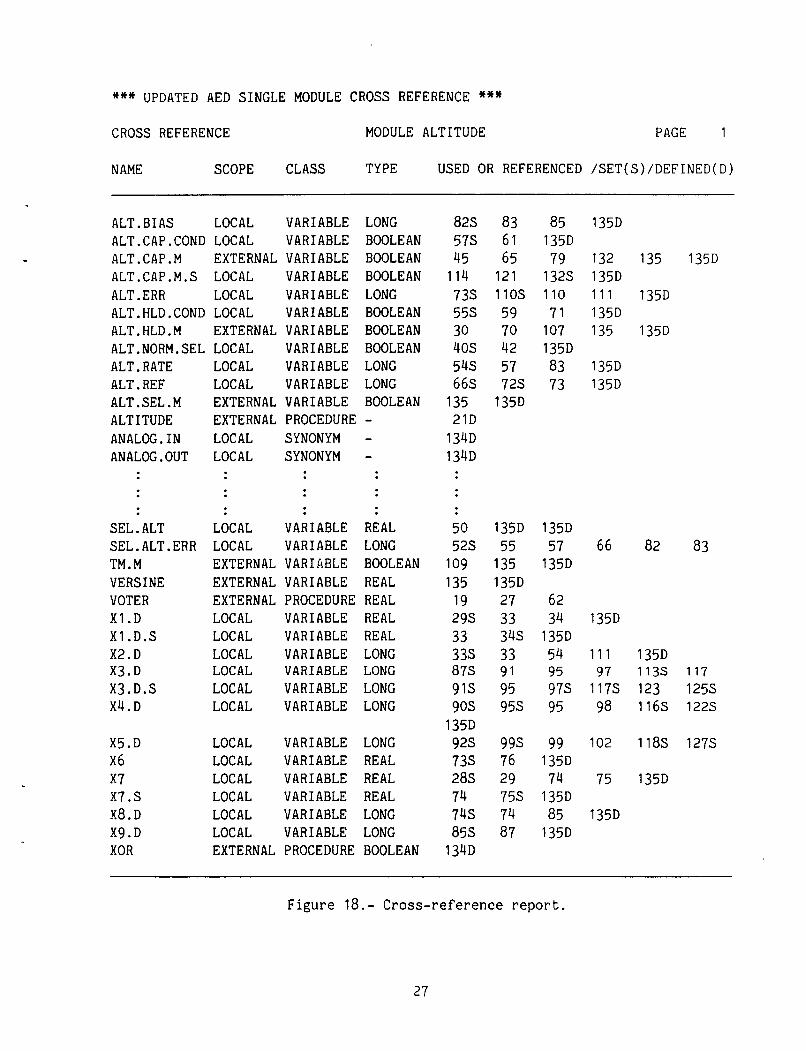
The -x option generates the cross-reference documentation report (fig. 18). report provides a "symbol" to cross reference each module analyzed (fig. 18). this guide the definition of symbol means an AED variable. All local symbols, exter- nal symbols, common symbols, and parameters referenced in the module are included. Symbol names are ordered alphabetically in the first column. The scope column indicates symbols known only in this module (LOCAL), external symbols (EXTERNAL), and common symbols (COMMON), and parameters (PARAMETER). The CLASS column identifies the symbol as a variable, a procedure, or a synonym. The TYPE column identifies the symbol type as a long, real, boolean, integer, or pointer. The last four columns identify every occurrence of a symbol by line number and if the symbol was used or referenced, set, or defined in a particular line.
This For
-r option: REACHING SET-
UNIX COMMAND EXAMPLE:
static -r ctrl.dat aforexec.aed
This command generates the REACHING SET analysis report for module aforexec.aed within the range specified in "ctrl.dat".
UNIVAC COMMAND EXAMPLE:
@XQT AMES*REACH.REACH @ADD,E AVFS$$.filename
The -r option generates the REACHING-SET analysis report. the REACHING-SET option, executes the module retesting capability of the V&V tools. When a set of untested decision-to-decision paths (DD-paths) has been iso- lated, the V&V tools help the user identify the sections of code f o r further test- ing. statement-line number and the ending-statement line number bounding the DD-path
The analysis specified by I
To reach the desired DD-path number, the user specifies the beginning 1
26
*** UPDATED AED SINGLE MODULE CROSS REFERENCE *** CROSS REFERENCE MODULE ALTITUDE PAGE 1
NAME SCOPE CLASS TYPE USED OR REFERENCED /SET(S)/DEFINED(D)
ALT . BIAS LOCAL VARIABLE LONG ALT.CAP.COND LOCAL VARIABLE BOOLEAN ALT.CAP.M EXTERNAL VARIABLE BOOLEAN ALT.CAP.M.S LOCAL VARIABLE BOOLEAN ALT. ERR LOCAL VARIABLE LONG ALT.HLD.COND LOCAL VARIABLE BOOLEAN ALT.HLD.M EXTERNAL VARIABLE BOOLEAN ALT.NORM.SEL LOCAL VARIABLE BOOLEAN ALT. RATE LOCAL VARIABLE LONG ALT. REF LOCAL VARIABLE LONG ALT.SEL.M EXTERNAL VARIABLE BOOLEAN ALTITUDE EXTERNAL PROCEDURE - ANALOG.IN LOCAL SYNONYM - ANALOC.OUT LOCAL SYNONYM -
SEL. ALT LOCAL VARIABLE REAL SEL.ALT.ERR LOCAL VARIABLE LONG TM.M EXTERNAL VARIABLE BOOLEAN VERSINE EXTERNAL VARIABLE REAL VOTER EXTERNAL PROCEDURE REAL X1 .D LOCAL VARIABLE REAL X1 .D.S LOCAL VARIABLE REAL X2.D LOCAL VARIABLE LONG X3.D LOCAL VARIABLE LONG X3.D.S LOCAL VARIABLE LONG X4.D LOCAL VARIABLE LONG
X5.D LOCAL VARIABLE LONG X6 LOCAL VARIABLE REAL x7 LOCAL VARIABLE REAL x7.s LOCAL VARIABLE REAL X8.D LOCAL VARIABLE LONG X9.D LOCAL VARIABLE LONG XOR EXTERNAL PROCEDURE BOOLEAN
82s 83 57s 61 45 65 114 121 73s 110s 55s 59 30 70 40s 42 54s 57 66s 72s 135 135D 21D 134D 134D
50 135D 52s 55 109 135 135 135D 19 27 29s 33 33 34s 33s 33 87s 91 91s 95 90s 95s
92s 99s 73s 76 28s 29 74 75s 74s 74 85s 87
135D
134D
85 135D 79 132s 110 71 107 135D 83 73
135D
132 135 135D 135D 1 1 1 135D 135D 135 135D
135D 135D
135D
135D 57 66 82 83
62 34 135D 135D 54 1 1 1 135D 95 97 113s 117 97s 117s 123 125s 95 98 116s 122s
99 102 118s 127s
74 75 135D
85 135D
135D
135D
135D
Figure 18.- Cross-reference report.
27
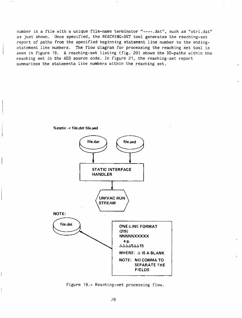
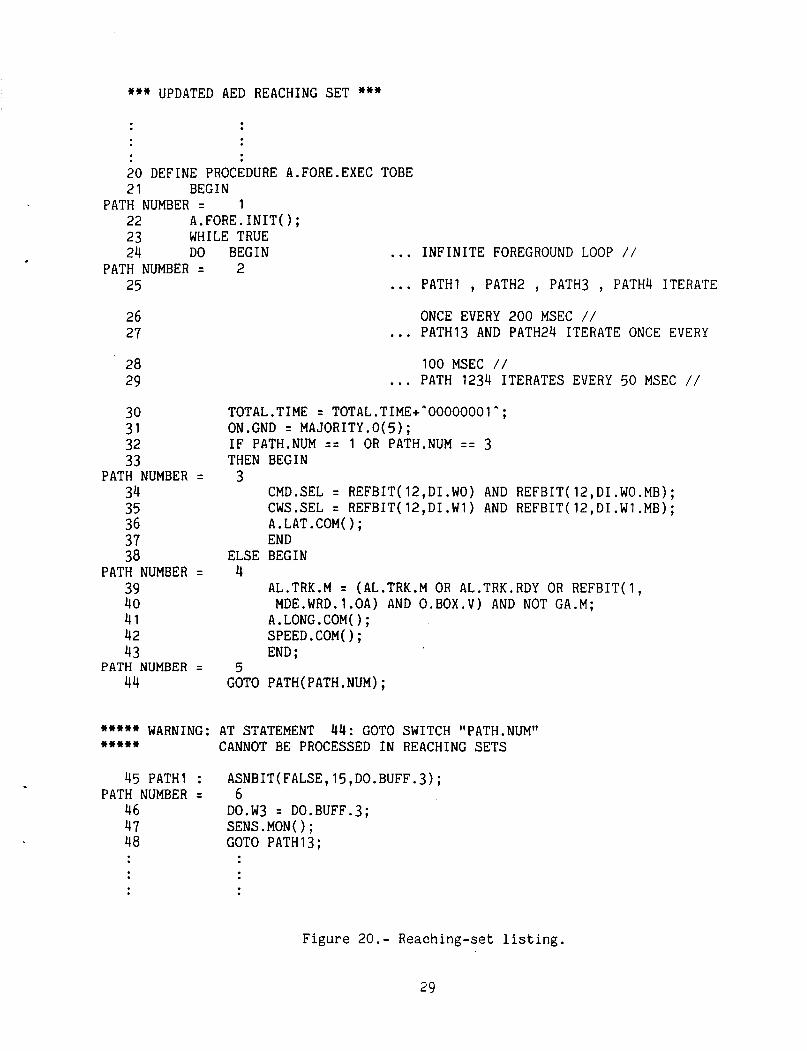
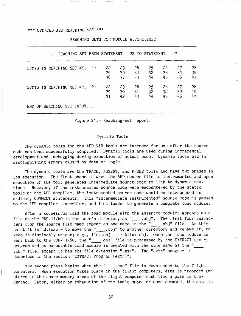
number in a file with a unique file-name terminator "---- .dat", such as "ctrl.dat" as just shown. report of paths from the specified beginning statement line number to the ending- statement line numbers. The flow diagram for processing the reaching set t oo l is seen in figure 19. reaching set in the AED source code. In figure 21, the reaching-set report summarizes the statements line numbers within the reaching set.
Once specified, the REACHING-SET tool generates the reaching-set I
~ A reaching-set listing (fig. 20) shows the DD-paths within the
%static -r file.dat file.aed
file.dat file.aed
STATIC INTERFACE HANDLER
UNIVAC RUN STREAM
NOTE:
ONE-LINE FORMAT (215) NNNNNXXXXX
A A A A 5 A A 1 5
WHERE: A IS A BLANK
NOTE: NO COMMA TO SEPARATE THE FIELDS
e.g.
Figure 19.- Reaching-set processing flow.
28
*** UPDATED AED REACHING SET ***
20 DEFINE PROCEDURE A.FORE.EXEC TOBE 21 BEGIN
PATH NUMBER = 1 22 A.FORE.INIT0; 23 WHILE TRUE 24 DO BEGIN ... INFINITE FOREGROUND LOOP / / 25 ... PATH1 , PATH2 , PATH3 , PATH4 ITERATE PATH NUMBER = 2
26 27
28 29
30 31 32 33
34 35 36 37 38
39 40 41 42 43
44
PATH NUMBER =
PATH NUMBER =
PATH NUMBER =
ONCE EVERY 200 MSEC / / ... PATH13 AND PATH24 ITERATE ONCE EVERY 100 MSEC / / ... PATH 1234 ITERATES EVERY 50 MSEC / /
TOTAL.TIME = TOTAL.TIME+*OOOOOOOIA; ON.GND = MAJORITY.O(S); IF PATH.NUM = = 1 OR PATH.NUM = = 3 THEN BEGIN
3 CMD.SEL = REFBIT(12,DI.WO) AND REFBIT(12,DI.WO.MB); CWS.SEL = REFBIT(12,DI.Wl) AND REFBIT(12,DI.Wl.MB); A.LAT.COM( ) ; END
ELSE BEGIN 4
AL.TRK.M = (AL.TRK.M OR AL.TRK.RDY OR REFBIT(1, MDE.WRD.1.OA) AND 0.BOX.V) AND NOT GA.M; A.LONG.COM(); SPEED.COM(); END ;
5 GOTO PATH(PATH.NUM);
***** WARNING: AT STATEMENT 44: GOTO SWITCH "PATH.NUMfl ***** CANNOT BE PROCESSED IN REACHING SETS
45 PATH1 : PATH NUMBER =
46 47 48
ASNBIT( FALSE, 15, DO.BUFF. 3) ;
DO.W3 = D0.BUFF.3; 6
SENS.MON0; GOTO PATH13;
Figure 20.- Reaching-set listing.
29
*** UPDATED AED REACHING SET *** REACHING SETS FOR MODULE A.FORE.EXEC
1. REACHING SET FROM STATEMENT 22 TO STATEMENT 47
STMTS IN REACHING SET NO. 1 : 22 23 24 25 26 27 28 29 30 31 32 33 34 35 36 37 43 44 45 46 47
STMTS IN REACHING SET NO. 2: 22 23 24 25 26 27 28 29 30 31 32 38 39 40 41 42 43 44 45 46 47
END OF REACHING SET INPUT ...
Figure 21.- Reaching-set report.
Dynamic Tools
The dynamic tools for the AED V&V tools are intended for use after the source code has been successfully compiled. development and distinguishing errors caused by data or logic.
Dynamic tools are used during incremental debugging during execution of actual code. Dynamic tools aid in
The dynamic tools are the TRACE, ASSERT, and PROBE tools and have two phases in its execution. The first phase is when the AED source file is instrumented and upon execution of the tool generates intermediate source code to link to dynamic rou- tines. However, if the instrumented source code were encountered by the static tools or the AED compiler, the instrumented source code would be interpreted as ordinary COMMENT statements. This "intermediate instrumented" source code is passed t o the AED compiler, assembler, and link loader to generate a complete load module.
After a successful load the load module with the asserted modules appears as a file on the PDP-11/60 in the user's directory as 'I- .obj". ters from the source file name appear as the name in the .obj" file. At this point it is advisable to move the "-.obj" to another directory and rename it, to keep it distinctly unique; e.g., 1ink.obj - - - > Alink.obj. Once the load module is sent back to the PDP-11/60, the 'I- .obj" file is processed by the EXTRACT (extr) program and an executable load module is created with the same name as the "-
.obj" file, except it has the file extension I'.exe". described in the section "EXTRACT Program (extr)".
The first four charac-
The "extr" program is
The second phase begins when the 'I- .exel' file is downloaded to the flight computers. When execution takes place in the flight computers, data is recorded and stored in the spare memory areas of the flight computer each time a path is tra- versed. Later, either by exhaustion of the table space or upon command, the data is
collected and uploaded to a data file on the PDP-11/60. When the data is on the PDP-11/60 it is massaged and dynamic reports are generated which help to show where retesting should be addressed in more detail. See the section "Symbolic Execution."
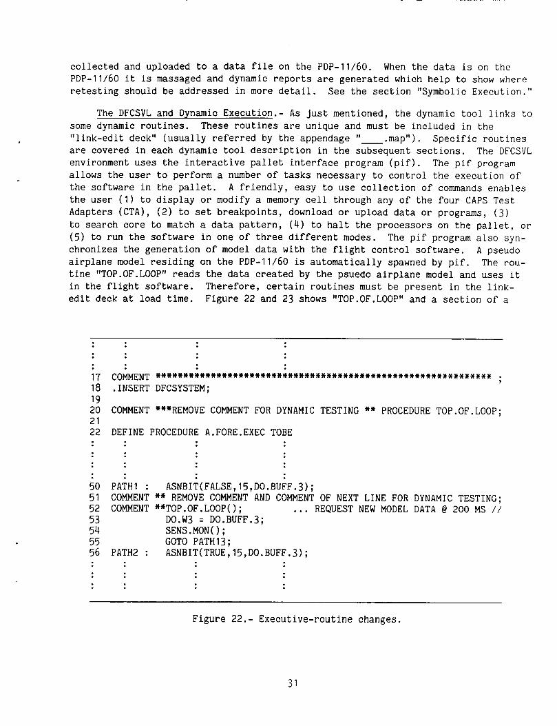
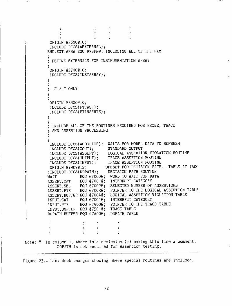
The DFCSVL and Dynamic Execution.- As just mentioned, the dynamic tool links to some dynamic routines. These routines are unique and must be included in the "link-edit deck" (usually referred by the appendage It- .map"). are covered in each dynamic tool description in the subsequent sections. The DFCSVL environment uses the interactive pallet interface program (pif). allows the user to perform a number of tasks necessary to control the execution of the software in the pallet. A friendly, easy to use collection of commands enables the user (1) to display or modify a memory cell through any of the four CAPS Test Adapters (CTA), (2) to set breakpoints, download or upload data or programs, (3) to search core to match a data pattern, ( 4 ) to halt the processors on the pallet, or (5) to run the software in one of three different modes. chronizes the generation of model data with the flight control software. A pseudo airplane model residing on the PDP-11/60 is automatically spawned by pif. tine ttTOP.OF.LOOPtt reads the data created by the psuedo airplane model and uses it in the flight software. Therefore, certain routines must be present in the link- edit deck at load time. Figure 22 and 23 shows "TOP.OF.LOOP" and a section of a
Specific routines
The pif program
The pif program also syn-
The rou-
17 COMMENT 18 .INSERT 19 20 COMMENT 21 22
50 51 52 53 54 55 56
. . . . . . . . . . . . . . . . . . . . . . . . . . . . . . . . . . . . . . . . . . . . . . . . . . . . . . . . . . . . . . DFCSYSTEM;
7
***REMOVE COMMENT FOR DYNAMIC TESTING ** PROCEDURE TOP.OF.LOOP; DEFINE PROCEDURE A.FORE.EXEC TOBE
PATH1 : ASNBIT(FALSE, 15,DO.BUFF.3); COMMENT ** REMOVE COMMENT AND COMMENT OF NEXT LINE FOR COMMENT **TOP.OF.LOOP(); ... REQUEST NEW MODEL
DO.W3 = D0.BUFF.3; SENS . MON( ) ; GOT0 PATH13;
PATH2 : ASNBIT(TRUE, 15,DO.BUFF.3) ;
DYNAMIC TESTING; DATA @ 200 MS / /
Figure 22.- Executive-routine changes.
31
ORIGiN @3600@,0; INCLUDE DFCS(AEXTERNAL);
END.EXT.ARRA EQU @3BFF@; INCLUDING ALL OF THE RAM
; DEFINE EXTERNALS FOR INSTRUMENTATION ARRAY 7
ORIGIN @3700@,0; INCLUDE DFCS(1NSTARRAY);
9
?
; F / T ONLY 7
ORIGIN @3BOO@,O; INCLUDE DFCS(FTCASE1; INCLUDE DFCS(FT1NSERTE);
?
; INCLUDE ALL OF THE ROUTINES REQUIRED FOR PROBE, TRACE ; AND ASSERTION PROCESSING t
?
INCLUDE DFCS(ALOOPT0P); INCLUDE DFCS(G0UT); STANDARD OUTPUT INCLUDE DFCS(ASSERT); INCLUDE DFCS(0UTPUT); TRACE ASSERTION ROUTINE INCLUDE DFCS(1NPUT); TRACE ASSERTION ROUTINE ORIGIN @79D9@,2;
WAITS FOR MODEL DATA TO REFRESH
LOGICAL ASSERTION VIOLATION ROUTINE
OFFSET FOR DECISION PATH ... TABLE AT "A00 ;INCLUDE DFCS(DDPATH); DECISION PATH ROUTINE WAIT EQU @7000@; WORD TO WAIT FOR DATA ASSERT.CAT EQU @7001@; INTERRUPT CATEGORY ASSERT.SEL EQU @7002@; SELECTED NUMBER OF ASSERTIONS ASSERT.PTR EQU @7003@; POINTER TO THE LOGICAL ASSERTION TABLE ASSERT.BUFFER EQU @7004@; INPUT .CAT EQU @7001@; INTERRPliT CATEGORY INPUT. PTR EQU @7500@; POINTER TO THE TRACE TABLE 1NPUT.BUFFER EQU @7501@; TRACE TABLE DDPATH.BUFFER EQU @7A00@; DDPATH TABLE
LOGICAL ASSERTION VIOLATION TABLE
9
Note: * In column 1 , there is a semicolon ( ; ) making this line a comment. DDPATH is not required f o r Assertion testing.
Figure 23.- Link-deck changes showing where special routines are included.
32
typical link deck with the special routines, respectively. In figure 23, the INCLUDE statement for ALOOPTOP causes the object module ALOOPTOP to be loaded. The command ALOOPTOP contains the entry point for "TOP.OF.LOOP."
The executive routine must have a PROCEDURE declaration and procedure call for "TOP.OF.LOOP". A section of code from an executive routine is presented below showing where the code should be changed. source code must be compiled and linked.
After the changes have been made, the
Each of the dynamic tools are discussed separately, but they do have a similar UNIX command format as seen below.
NAME assert - process AED source for assertions. probe trace - process AED source for 1/0 assertions.
- process AED source for path instrumentation.
SYNOPSIS assert probe [ -c class] [-mp#] [-mtb] [-z] -1 mapfile.map AED - file ... trace
..(files must end in [.sed], [.fof] or [.isd])
DESCRIPTION The dynamic command (assert, probe or trace) invokes the V&V dynamic tool on the Univac 1100. The command accepts publicly readable files whose file names end with .aed for AED source modules; .fof for file-of-files or .isd for files residing on the Univac computer site. Files ending in .aed or .fof may be sent at the same time. Files ending in .isd must all be sent together and must reside on the Univac 1100 computer. The module is instrumented, compiled, assembled, and link edited, and the output is routed as specified by the following flag arguments.
Output listings from the Univac are routed to the user's directory on the PDP-11/60 with a file name consisting of the first four characters from the first file name with a ('.obj" extension attached.
The following arguments are interpreted by the dynamic tool:
-c Univac 1100 job priority. Priorities range from A through Z, the highest to lowest priority, respectively. The default is class A (standard).
33
-mp# This option allows the user t o specify the maximum number of pages for the Univac 1100 printout. used by this command is computed based on the number of files (AED modules) which is approximately 16 pages per file; e.g., -mpW
The default number of pages
-mt% This option allows the user to specify the maximum time for execution on the Univac 1100. A number preceded by an "s" (e.g., -mts4O) is assumed t o be in seconds. The default time limit used by this command is computed based on the number of files (AED modules), approximately 60 sec/file.
-z The z option allows for debugging or displaying the run stream to determine if the run was generated correctly. See static tool format for detailed description of the -z option.
-1 This flag is required for dynamic processing. It is to link the program from a file, It- .map", which specifies modules, addresses, and so on, for the link editor. The 'I .map" MUST BE PRESENT with the -1 option.
Each tool will be discussed in detail.
NOTE Source files manipulated by this command must be publicly readable in order for them to be copied t o the RJE queue or accessable on the Univac.
DIAGNOSTICS The job may successfully be sent to the Univac 1100 but fail to run for many reasons. cryptic messages why the run failed. If it is not obvious, seek a user consultant for diagnostic help.
The user's output listing will contain one or more
Instrumenting the Source Code.- A module is instrumented by placing assertion statements in areas of the source code where variables or logic paths are to be tested. The ASSERT and TRACE dynamic tools interpret the instrumented source, generate dynamic tool numbers, and insert linkage to dynamic routines in the source code. Because these dynamic tool numbers exist and the source has been instru- mented, the modules must be compiled, assembled, and linked to keep the dynamic tool numbers consistent. The dynamic tool numbers are referenced by the report generator to produce dynamic tool reports after execution.
An exception to the instrumentation process is the PROBE dynamic tool. The PROBE dynamic tool performs a path analysis on the AED source code first, then generates dynamic tool numbers and inserts the linkage dynamic routines in the
34
source code. The subsequent procedures for the PROBE tool after the source code has been instrumented is the same as for the ASSERT and TRACE tool.
Assertion Tool.-
UNIX COMMAND EXAMPLE:
assert -1 Alink.map alatcom.aed
This command calls on the ASSERTION tool to generate and insert linkage to dynamic routines for the AED module alatcom. Then compile, assemble and link the module based on the link-edit deck, "Alink.map".
UNIVAC COMMAND EXAMPLE:
@XQT AMES*ASSERT.ASSERT @ADD,E AVFS$$.filename
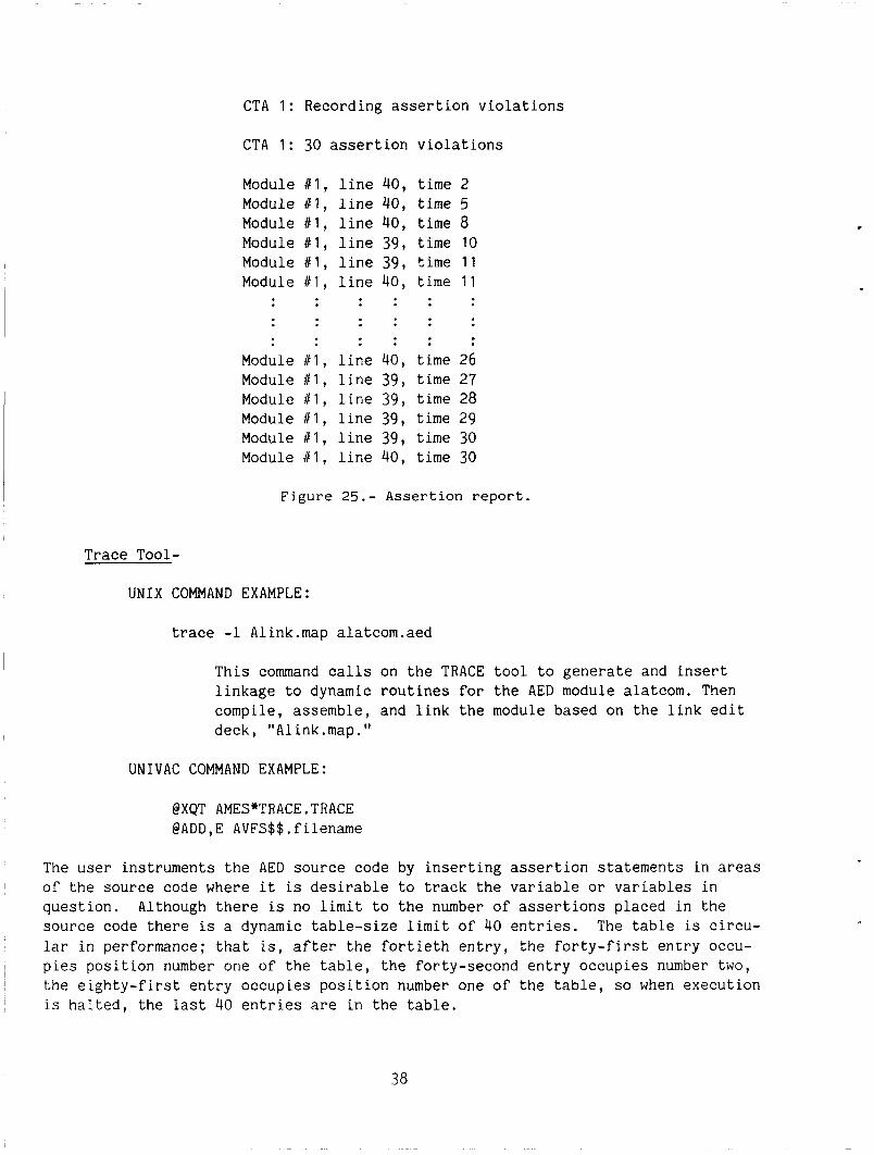
The user instruments the AED source code by inserting assertion statements in areas of the source code to track a variable or variables. A maximum of 30 assertion statements is allowed in the source code. Assertions can be placed:
After subprogram entry Before subprogram exit After subprogram invocations A t decision points Within long computations Where data enters Where boundary checks should be made
There are several formats available for assertion statements in the source code. They are l i s t ed ( n o t ranked) a s follows:
COMMENT ASSERT* boolean expression;
COMMENT ASSERT* ALL control IN (initial value, final value) boolean expression;
COMMENT ASSERT* SOME control IN (initial value, final value) boolean expression;
COMMENT INITIAL* -- synonym of ASSERT. COMMENT FINAL* -- synonym of ASSERT.
35
Examples
COMMENT ASSERT* HEIGHT >500;
COMMENT ASSERT* ALL I I N ( 1 , N ) X(I) > Y ( I ) ;
COMMENT ASSERT* SOME I IN(1,M) X ( 1 ) == 3000.0;
After t h e AED s o u r c e module h a s been a s s e r t e d , t h e s o u r c e module is ana lyzed by the ASSERT t o o l and an i n t e r m e d i a t e f i l e c o n t a i n i n g dynamic t o o l numbers and l i n k s t o dynamic a s s e r t i o n r o u t i n e s is g e n e r a t e d . T h i s i n t e r m e d i a t e f i l e is passed t o t h e AED p r o c e s s o r s f o r f u r t h e r p r o c e s s i n g . f i l e named "TABFIL" on t h e Univac. The TABFIL f i l e is l i s t e d and r e t u r n e d t o t h e PDP-11/60 a long w i t h t he r e s u l t s from t h e AED p r o c e s s o r s . subsequen t ly used by t h e r e p o r t g e n e r a t o r .
The dynamic t o o l numbers are retained i n a
T h i s p r i n t o u t p u t is
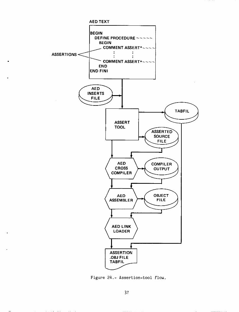
A s p e c i a l n o t e f o r t h e program u s i n g a s s e r t i o n s . The l i n k - e d i t deck MUST OMIT F igure 24 d e p i c t s t h e the "INCLUDE program-file(DDPATH);" f o r the l o a d i n g p r o c e s s .
f low o f t h e AED s o u r c e from i n p u t t o t h e l o a d module ' s comple t ion .
F igu re 25 shows t h e r e s u l t s o f t h e ASSERTION r e p o r t . In f i g u r e 25, Modu a dynamic too l number a s s i g n e d by the ASSERT t o o l ; t h e l i n e number references s t a t e m e n t number w i t h i n t h e module where t h e a s s e r t i o n v i o l a t i o n h a s occur red t he n t h t i c k time. Each t i c k is 50 msec.
e 1 is t h e and a t
36
r
BEGIN DEFINE PROCEDURE -----
BEGIN COMMENT ASSERT*----
c:a INSERTS
ASSERTIONS <
TABFIL
ASSERT
' COMMENT ASSERT*---- END
END FIN1
SOURCE
COMPILER CROSS OUTPUT
COMPl LE R
I 9 I
AED ASSEM B L E R
I f-l AED LINK
ASSE RT ION .OBJ FILE TABFIL
Figure 24.- Assertion-tool flow.
37
CTA 1: Recording assertion violations
CTA 1: 30 assertion violations
Module Module Module Module Module Module
Module Module Module Module Module Module
i l l , # I , 81, 111, 11 1 , # 1 ,
111, 6 1 , 111, 111, 111, c1 ,
line 40, line 40, line 40, line 39, line 39, line 40,
line 40, line 39, line 39, line 39, line 39, line 40,
time 2 time 5 time 8 time 10 time 11 time 1 1
time 26 time 27 time 28 time 29 time 30 time 30
Figure 25.- Assertion report.
Trace Tool-
UNIX COMMAND EXAMPLE:
trace -1 Alink.map alatcom.aed
This command calls on the TRACE tool to generate and insert linkage to dynamic routines for the AED module alatcom. Then compile, assemble, and link the module based on the link edit deck , A1 ink . map. 'I
UNIVAC COMMAND EXAMPLE:
@XQT AMES"TRACE.TRACE @ADD,E AVFS$$.filename
The user instruments the AED source code by inserting assertion statements in areas of the source code where it is desirable to track the variable or variables in question. Although there is no limit to the number of assertions placed in the source code there is a dynamic table-size limit of 40 entries. lar in performance; that is, after the fortieth entry, the forty-first entry occu- pies position number one of the table, the forty-second entry occupies number two, the eighty-first entry occupies position number one of the table, so when execution is halted, the last 40 entries are in the table.
The table is circu-
The TRACE tool automatically processes the TRACE assertion statements "COMMENT INPUT* ---- It and "COMMENT OUTPUT* ---- I t , but the "COMMENT ASSERT* ---- statements cause the TRACE tool problems. Do not include the "COMMENT ASSERT* ---- It statements in the source code.
The user has two formats available to put a TRACE assertion statement in the source code. They are listed (not ranked) as follows:
COMMENT INPUT* expression;
COMMENT OUTPUT* expression;
Examples
COMMENT INPUT* BOOLEAN ALIGN;
COMMENT OUTPUT* LONG TOTAL.TIME;
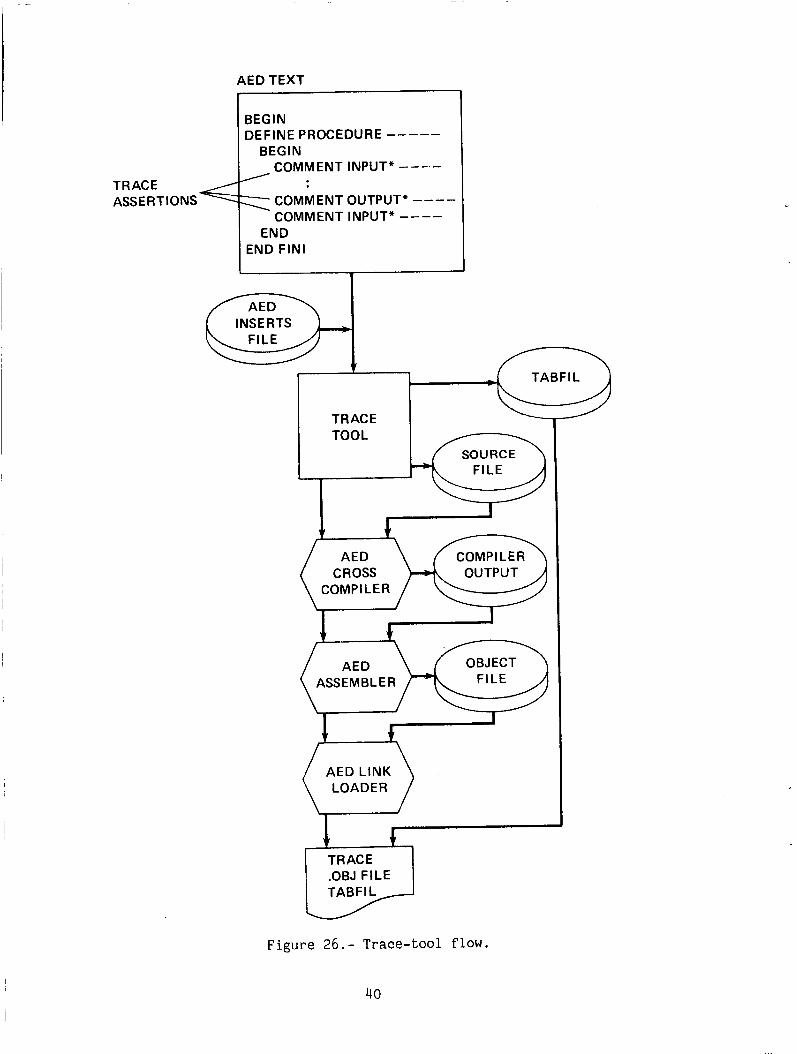
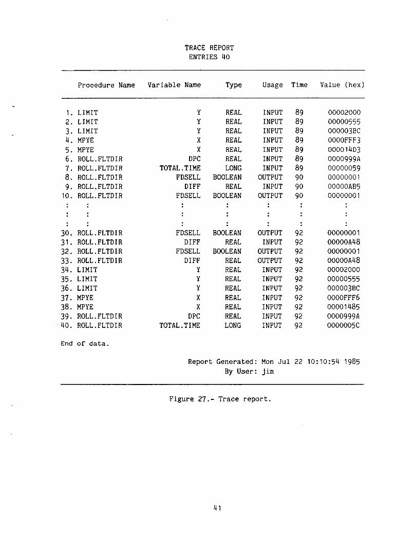
After the AED source module has been asserted, the source module is analyzed by the TRACE tool, and an intermediate file containing links to dynamic trace routines is generated. This intermediate file is passed to the AED processors for further processing. IIINCLUDE program-file(DDPATH);" in the link-edit deck. of the AED source from input to load-module completion. of the TRACE report in ascending time.
The link edit deck for the module having assertions MUST OMIT the Figure 26 depicts the flow Figure 27 shows the results
39
AED TEXT
BEGIN DEFINE PROCEDURE -----
BEG IN COMMENT INPUT* ----
COMMENT OUTPUT* ---- COMMENT INPUT* ----
TRACE ASSE R T I ONS
END FIN1
INSERTS a TABFIL
TRACE
i I
AED CROSS
COMP I LE R
AED LINK LOADER
TRACE .OBJ FILE TABFIL
Figure 26.- Trace-tool flow.
40
TRACE REPORT ENTRIES 40
Procedure Name Variable Name TY Pe Usage Time Value ( h e x )
1. 2. 3. 4. 5. 6. 7. 8. 9. 10.
LIMIT LIMIT LIMIT MPYE MPY E ROLL.FLTDIR ROLL.FLTDIR ROLL.FLTDIR ROLL.FLTDIR ROLL.FLTDIR
30. ROLL.FLTDIR 31. ROLL.FLTDIR 32. ROLL.FLTDIR 33. ROLL.FLTDIR 34. LIMIT 35. LIMIT 36. LIMIT 37. MPYE 38. MPYE 39. ROLL.FLTDIR 40. ROLL.FLTDIR
Y Y Y X X
DPC TOTAL.TIME
FDSELL DIFF
FDSELL
FDSELL DIFF
FDSELL DIFF
Y Y Y X X
DPC TOTAL.TIME
REAL REAL REAL REAL REAL REAL LONG
BOOLEAN REAL
BOOLEAN
BOOLEAN REAL
BOOLEAN REAL REAL REAL REAL REAL REAL REAL LONG
INPUT INPUT INPUT INPUT INPUT INPUT INPUT
OUTPUT INPUT
OUTPUT
OUTPUT INPUT
OUTPUT OUTPUT INPUT INPUT INPUT INPUT INPUT INPUT INPUT
89 89 89 89 89 89 89 90 90 90
92 92 92 92 92 92 92 92 92 92 92
00002000 00000555 000003BC 0000FFF3 0000 14D3 000099 9 A 00000059 0000000 1 OOOOOAB5 0000000 1
0000000 1 OOOOOA48 0000000 1 00000A48 00002000 00000555 000003BC 0000FFF6 0000 1485 0000999A 0000005C
End of data.
Report Generated: Mon Jul 22 10:10:54 1985 By User: Jim
Figure 27.- Trace report.
41
Probe Tool-
UNIX COMMAND EXAMPLE:
probe -1 Alink.map rollfltdir.aed
This command calls on the PROBE tool to generate and insert linkage to dynamic routines for the AED module rollfltdir. Then compile, assemble, and link the module based on the link-edit deck, "Alink.map."
UNIVAC COMMAND EXAMPLE:
@XQT AMES*PROBE.PROBE @ADD,E AVFS$$.filename
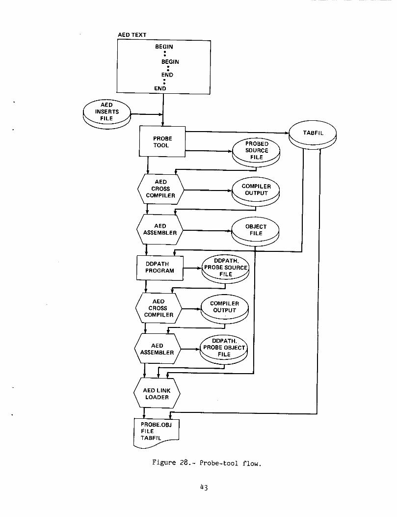
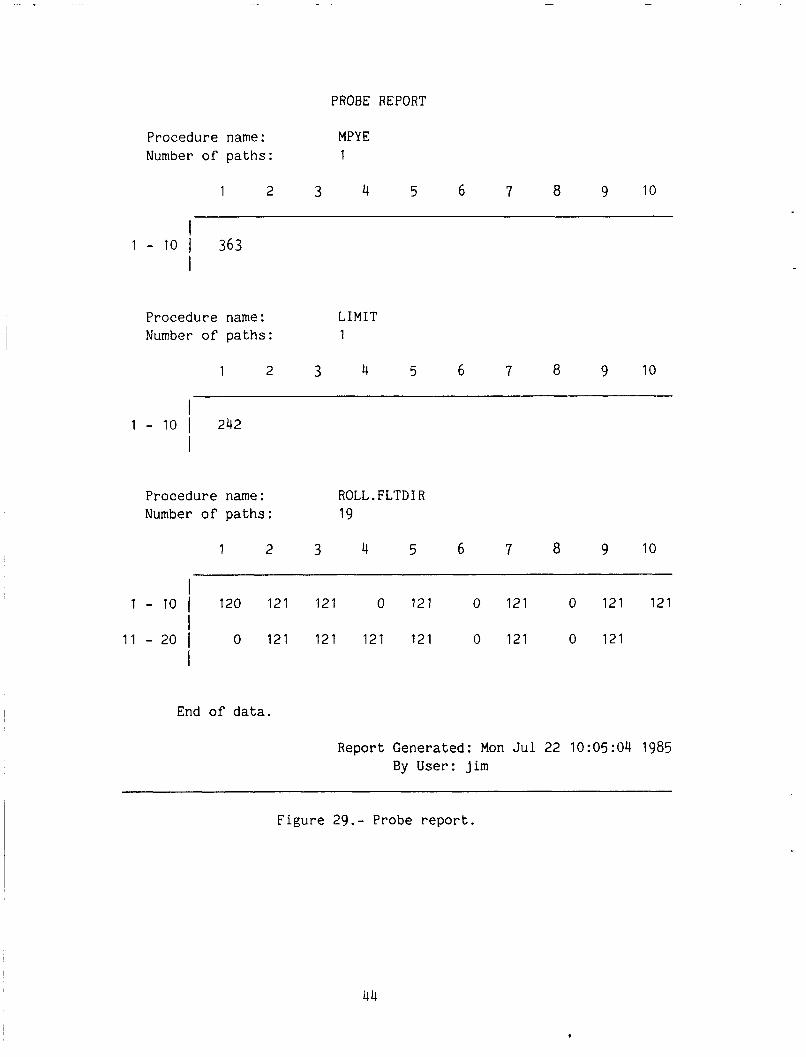
No instrumentation is necessary of the AED source module prior to the execution of the PROBE tool. Once the PROBE tool is executed, a data-path analysis is performed on the AED source code and for each data path a link is generated to the dynamic PROBE routine. This intermediate source code is passed to the AED processors for compiling, assembling, and linking. The link-edit deck for the dynamic PROBE execu- tion MUST include the "INCLUDE program-file(DDPATH) ;IT. Figure 28 depicts the flow of the AED source from input to load-module completion. Figure 29 shows the PROBE report after dynamic-flight software execution with PROBE routines collecting data during execution.
42
AED TEXT
BEGIN 0 0
BEGIN
END
e 0
0 e
END I
PROBE
SOURCE
COMPl LER OUTPUT
COMPl LE R OUTPUT CROSS
COMPILER
AED LINK (, LOADER ,)
PROBE.OBJ
TABFIL
Figure 28.- Probe-tool flow.
43
PROBE REPORT
Procedure name: MPYE Number of p a t h s : 1
1 2 3 4 5 6 7 8 9 10
I
I 1 - 10 I 363
Procedure name: LIMIT Number of p a t h s : 1
1 2 3 4 5 6 7 8 9 10
I
I 1 - 10 I 242
Procedure name: ROLL.FLTDIR Number of p a t h s : 19
1 2 3 4 5 6 7 8 9 10
0 121 0 121 0 121 121 I
I 11 - 20 I
I
1 - 10 I 120 121 121
0 121 121 121 121 0 121 0 121
End of d a t a .
Report Gene ra t ed : Mon J u l 22 10:05:04 1985 By User: j i m
F i g u r e 29.- Probe r e p o r t .
44
Symbolic Execution
UNIX COMMAND EXAMPLE:
symbolic ctrl.dat hdgsel.aed
I -
, -
This command symbolically executes the module hdgsel.aed within the range specified in the control file "ctrl.dat," and generate a symbolic execution or verification condition generation report .
UNIVAC COMMAND EXAMPLE:
@XQT AMES*SYMEXEC.SYMEXEC @ADD,E AVFS$$.filename
Symbolic execution, verification condition generation (VCG), or formal verification (as it is often called) of variables or expressions can be used to verify a module's output is the same as the formula it has been specified to compute. execution of assertions is termed "verification conditions." verification conditions for a module are true, it is said the module has been for- mally verified with its assertions.
The symbolic By showing that the
Two steps are required to perform symbolic-execution or verification-condition The first step is a preliminary step to obtain the necessary data; the generation.
second step is the actual generation. The program verifier uses line numbers of AED source modules to perform symbolic execution.
The UNIX command format for symbolic execution is as shown in the following list:
NAME
symbolic - AED Symbolic Execution SYNOPSIS
symbolic [-c class] [-mp#] [-mt#] [-z] file.dat AED-file ... ..(files must end in [.aed], [.fof] or [.isd])
DESCRIPTION
The symbolic command invokes the AED Symbolic Execution tool on the UNIVAC 1100. Variables are initialized to their default values in the module specified for the range specified in the control file ending with the file extension .dat. It accepts publicly readable files whose file names end with .aed for AED source modules, . fo f for file of files, or .isd for files
45
residing on the Univac computer site. Files ending in .aed or .fof may be sent at the same time. together and must reside on the Univac 1100 computer. analyzed and outputs are routed as specified by the following flag arguments.
Files ending in .isd must all be sent The module is
Output listings from the Univac are routed to the user's directory on the PDP-11/60 with a file name consisting of the first four characters from the first file name with a ".rpt" extension attached.
The following arguments are interpreted by Symbolic:
-c Univac 1100 job priority. Priorities range from A through Z, the highest to lowest priority, respectively. The default is class A (standard).
-mp# This option allows the user to specify the maximum number of pages for the Univac 1100 printout. used by this command is computed based on the number of files (AED modules) which is approximately 16 pages per file; e.g., -mp50.
The default number of pages
-mt# This option allows the user to specify the maximum time for execution on the Univac 1100. A number preceded by an "S" (e.g., -mts4O) is assumed to be in seconds. The default time limit used by this command is computed based on the number of files (AED modules) approximately 60 sec/file.
-z The z option allows for debugging or displaying the run stream to determine if the run was generated correctly. See static tool format for detail description of the -z option.
NOTE Source files manipulated by this command must be publicly readable in order for them to be copied to the RJE queue o r accessable on the Univac.
DIAGNOSTICS The job may successfully be sent to the Univac 1100, but may fail to run for many reasons. The user's output listing will contain one or more cryptic messages why the run failed. obvious, seek a user consultant for diagnostic help.
If the problem is not
The symbolic execution control file, "filename.dat," is basically a FORTRAN "FOR" statement loop. The first statement is the "FOR" statement in the form
46
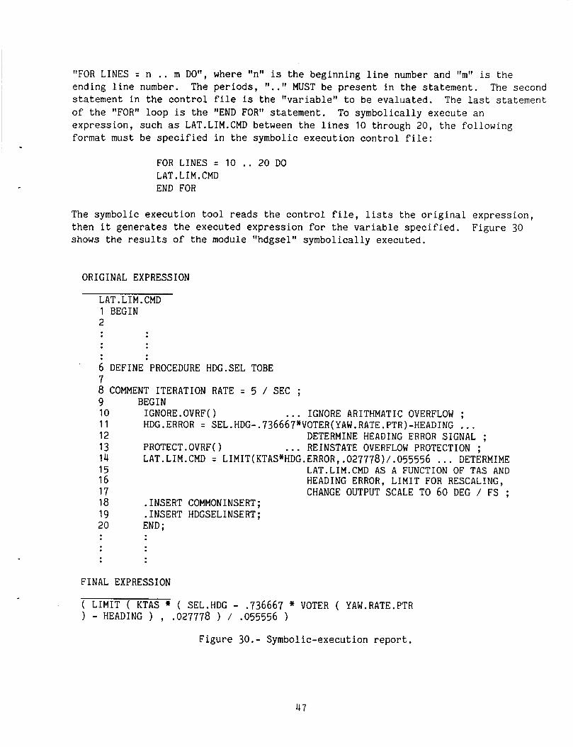
"FOR LINES = n .. m DO", where "n" is the beginning line number and 'hrl is the ending line number. The periods, ".." MUST be present in the statement. The second statement in the control file is the "variable" to be evaluated. The last statement of the "FOR" loop is the "END FOR" statement. expression, such as LAT.LIM.CMD between the lines 10 through 20, the following format must be specified in the symbolic execution control file:
To symbolically execute an
FOR LINES = 10 .. 20 DO LAT.LIM.CMD END FOR
The symbolic execution tool reads the control file, lists the original expression, then it generates the executed expression for the variable specified. shows the results of the module "hdgsel" symbolically executed.
Figure 30
ORIGINAL EXPRESSION
LAT.LIM.CMD 1 BEGIN
6 DEFINE PROCEDURE HDG.SEL TOBE 7 8 COMMENT ITERATION RATE = 5 / SEC ; 9 BEGIN 10 IGNORE.OVRF0 ... IGNORE ARITHMATIC OVERFLOW ; 12 DETERMINE HEADING ERROR SIGNAL ; 13 PROTECT.OVRF() ... REINSTATE OVERFLOW PROTECTION ; 14 LAT.LIM.CMD = LIMIT(KTAS*HDG.ERROR, .027778)/.055556 . . . DETERMIME 15 LAT.LIM.CMD AS A FUNCTION OF TAS AND 16 17 CHANGE OUTPUT SCALE TO 60 DEG / FS ; 18 .INSERT COMMONINSERT; 19 .INSERT HDGSELINSERT; 20 END ;
1 1 HDG.ERROR = SEL.HDG-.736667*VOTER(YAW.RATE.PTR)-HEADING ...
HEADING ERROR, LIMIT FOR RESCALING,
FINAL EXPRESSION
( LIMIT ( KTAS * ( SEL.HDG - .736667 * VOTER ( YAW.RATE.PTR ) - HEADING ) , .O27778 ) / .055556 )
Figure 30.- Symbolic-execution report.
47
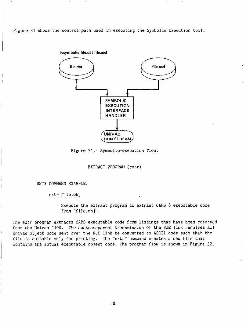
1 Figure 31 shows the control path used in executing the Symbolic Execution tool.
%symbolic file.dat file.aed
SYMBOL IC EXECUTION INTERFACE
Figure 31.- Symbolic-execution flow.
EXTRACT PROGRAM (extr)
UNIX COMMAND EXAMPLE:
extr file.obj
Execute the extract program to extract CAPS 6 executable code from I' f i le. ob j '' .
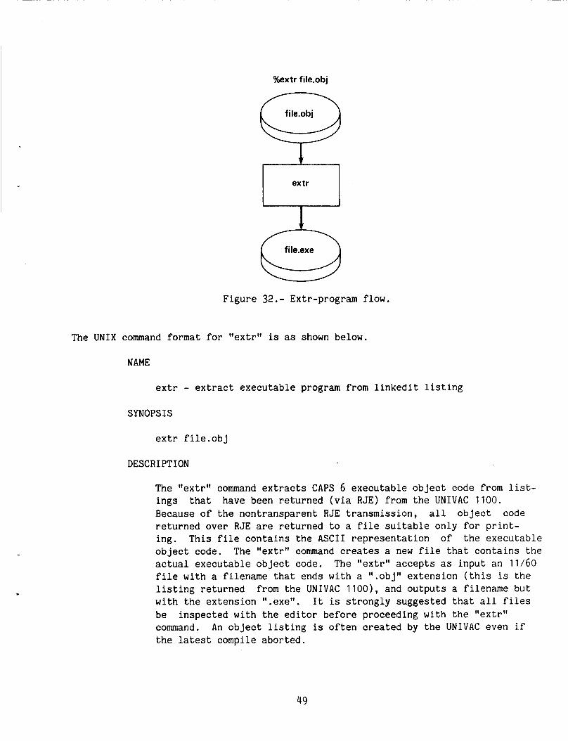
The extr program extracts CAPS executable code from listings that have been returned from the Univac 1100. Univac object code sent over the RJE link be converted t o ASCII code such that the file is suitable only fo r printing. contains the actual executable object code. The program flow is shown in Figure 32.
The nontransparent transmission of the RJE link requires all
The "extr" command creates a new file that
48
%extr file.obj
file.obj Q l -
file.exe Q F i g u r e 32.- Extr-program flow.
The U N I X command format for " e x t r t l is as shown below.
NAME
extr - extract e x e c u t a b l e program from l i n k e d i t l i s t i n g
SYNOPSIS
e x t r f i l e .ob j
DESCRIPTION
The "extr" command extracts CAPS 6 e x e c u t a b l e object code from list- i n g s t h a t have been r e t u r n e d ( v i a R J E ) from t h e U N I V A C 1100. Because o f the n o n t r a n s p a r e n t RJE t r a n s m i s s i o n , a l l object code r e t u r n e d o v e r RJE are r e t u r n e d to a f i l e s u i t a b l e o n l y for p r i n t - i n g . T h i s f i l e c o n t a i n s t h e ASCII r e p r e s e n t a t i o n of the e x e c u t a b l e object code. The " e x t r " command creates a new f i l e t h a t c o n t a i n s t h e a c t u a l e x e c u t a b l e object code. f i l e w i t h a f i l ename t h a t ends w i t h a ".obj" e x t e n s i o n ( t h i s is the l i s t i n g r e t u r n e d from t h e U N I V A C 1100), and o u t p u t s a f i l e n a m e b u t w i t h the e x t e n s i o n I1.exe". I t is s t r o n g l y sugges t ed t h a t a l l f i l e s be i n s p e c t e d w i t h t h e edi tor before proceeding w i t h t h e " e x t r " command. An o b j e c t l i s t i n g is o f t e n created by the UNIVAC even i f t h e la tes t compile a b o r t e d .
The ttextrll a c c e p t s as i n p u t an 11/60
49
DIAGNOSTICS
"Filename not created with CARTRIDGE TAPE . . . ' I
The .obj" file provided was not created using the ''-1" option to "axc [avfs]" or the file was somehow truncated (possibly because of a bad RJE transmission). in the editor or print the contents of the file for examination.
Examine the file
"Truncated object file" This message occurs when the object file that has been input is somehow incomplete. The file could have been interrputed while being transmitted, the UNIVAC run may have terminated abnormally (aborted because of maximum pages, etc.). Examine the file in the editor or print the contents of the file for examination.
EXAMPLES
extr Alink.obj The 11/60 file "Alink.obj" is read and the extr program determines if it was created with the cartridge tape trans- mission program. I f so, a f i l e named "Alink.exe" is created which contains the executable program to be downloaded to the pallet .
PALLET INTERFACE PROGRAM (pif)
UNIX COMMAND EXAMPLE:
pif Execute the pallet interface program t o perform a variety of tasks on the pallet.
The pif is an interactive UNIX program which accepts commands to perform a variety of tasks necessary to control the execution of the software in the pallet. A friendly, easy to use collection of commands enables the user to display o r modify a memory cell in the flight computers through any of the four CTAs, set breakpoints, download or upload data or programs, search core to match a data pattern, halt the processors on the pallet, or run the software in one of three different modes. pif also synchronizes the generation of model data with the flight control soft- ware. cally spawned by pif.
The
The airplane model resides in a file named /avfs/bin/model and is automati-
50
The UNIX command format for "pif" is as shown below.
NAME
pif - pallet interface program SYNOPSIS
pif [-a assert - file] [-t trace - file]
DESCRIPTION
The pif command invokes the interactive pallet interface program. This program allows a user to perform a number of tasks necessary to control the execution of the software in the pallet. A friendly, easy to use collection of commands enables the user to display o r modify a memory cell through any of the four CTAs, set breakpoints, download o r upload data or programs, search core to match a data pattern, halt the processors on the pallet, or run the software in one of three different modes. The pif synchronizes the generation of model data with the flight-control software. The airplane model resides in a file named /avfs/bin/model and is automatically spawned by pif.
The following arguments are interpreted by pif:
-a assert - file
Logical assertion violations accumulated during dynamic testing is accumulated in the file "assert file". This file is an ASCII file containing the dynamic data produced by the software tools. The default is to print the data on the DEC-writer. See the description of the AED V&V tool assert.
-t trace-file
Dynamic data generated by the AED V&V trace tool is accumulated in file "trace - file". report using the Report Generator, "rpt". Omission of this option causes the trace data to remain on the pallet where it was accumulated. See trace and Report Generator descriptions.
This data may later be formatted into a
Once pif is called, it prompts the user for the input of a command. The following commands are recognized by pif:
51
"help [command]"
The help command provides the user with the proper syntax and usage of the legal pif commands. arguments provides a list of the legal commands and their asso- ciated syntax. The "command" argument to help is assumed to be the name of a command that the user requires additional infor- mation. The command "help help" provides information similar to that in this paragraph.
The "help" command without any
"ctas [number-of-ctas]"
The ctas command allows the user to change the number of CTAs in use by pif. number of CTAs currently in use. This may be changed by using the optional argument "number - - of ctas". enables the user to access all four CTAs, "ctas 3" allows CTAs 1, 2, and 3 to be accessed, etc. The default allows the user to access CTAs 1 and 2.
The command "etas" with no arguments echos the
The command "ctas 4"
"base [octal I decimal 1 hex]"
The base command is used t o change or display the working number system used by pif. the current number system (octal, decimal, or hexadecimal). The optional argument t o base is used if the user wishes to change the number system. to decimal (unsigned decimal), etc. The default base is hexadecimal.
The command "base" with no arguments echos
The command "base decimal" changes the base
"quit
This command simply exits pif and returns the user to UNIX. model is terminated and intermediate files created by the model are removed. The use of this command causes a normal exit.
The
The halt command is used to halt the execution of the flight- control software in the CAPS. It only halts those processors currently in use by pif.
"search [caps - address value ] 'I
Search is a routine that sequentially reads through through CAPS core and compares each memory cell to the bit pattern speci- fied. As with all of the other pif commands the two arguments (caps-address and value) are taken to be values specified in the
5 2
current working number system (see the "base" command). Hence, if the command input is "search 1.100 0667", and the working number system is hexadecimal, pif begins searching at address hexadecimal 100 on CTA /I1 and stops when it finds a cell that contains hexadecimal 0667. leading zeros, all bit patterns are right justified in the word. If no match is found, the user is notified. The command "search" with no arguments begins searching at "the last address that contained a match" + 1 for the same data pattern. This command enables a user to find all occurrences of the data pattern without having to retype the entire command several times. If the working number system is octal and the command "search 1.100 888" is given, unusual results will occur.
It is not really necessary to type
"break [caps - address] [data]"
The break command is used to set the breakpoint bit in the control register of the specified CTA. Only one breakpoint may be set for each CTA. may be set. The first is an "address breakpoint." causes a bus halt when the specified address occurs of the transfer bus. When a breakpoint is encountered on any CTA, all CTAs are halted by pif and the user is notified. This type of breakpoint may be set by specifying the "caps address" argument and not the "data" argument. For example, "break 2.3F66" sets CTA #2 to bus halt when the address 3F66 occurs on its transfer bus. TPs second type of breakpoint that may be set is an "address and data breakpoint." It is set by specifying both arguments to the break command. The command "break 3.548A 1010" causes a bus halt on CTA #3 when the address 548A is on its transfer bus and that address contains the value 1010. The "break" command with no arguments cancels all breakpoints on all CTAs.
There are two types of breakpoints that This type
%on i tor
The monitor command allows the user to display and/or modify the contents of any positive address in the CAPS memory. Note that a positive address is one which is not on the 1/0 page. Monitor can access addresses up to and including "7FFF" and display them one at a time, or dump 50 values with a single key-stroke. operation of this routine includes a subset of the directives allowed by the Monitor program that runs on the PDP 11/04 on the pallet. Once the monitor command is issued, the following subcommands are legal:
The
ll/lt Display current address, see notes regarding buffering below.
53
"\" Display c u r r e n t address - 1 , and back up p o i n t e r .
Disp lay c u r r e n t address + 1 , and move p o i n t e r forward.
It ( s p a c e ) Dump t h e b u f f e r and increment p o i n t e r ( c o n t a i n s 50 memory l o c a t i o n s 1 .
"q" Q u i t ( e x i t ) t h e moni tor p r o c e s s o r and r e t u r n t o p i f .
A memory c e l l is modi f ied by t y p i n g t h e a d d r e s s (CTA.address. . . lll.lOOO" for example) , fo l lowed by a ''/" d i r e c t i v e , t h e n t y p i n g a new v a l u e . I t is i m p o r t a n t t o n o t e t h a t t h i s moni tor r o u t i n e d i f f e r s from t h e 11/04 r o u t i n e i n many ways. Most i m p o r t a n t is t h e fact t h a t a l l 1/0 i n t h e 11/60 v e r s i o n is b u f f e r e d . Repeatedly t y p i n g 'I/'' w i l l n o t n e c e s s a r i l y d i s p l a y an updated memory l o c a t i o n . The b u f f e r may be w r i t t e n t o CAPS memory by t y p i n g a c a r r i a g e r e t u r n . The same a p p l i e s t o m o d i f i c a t i o n of a p a r t i c u l a r l o c a t i o n . Again, the l o c a t i o n is updated when a new v a l u e is e n t e r e d followed by a c a r r i a g e r e t u r n .
"upld [-VI cta.address word-count 11/60 - f i le"
The "upld" command u s e s t h e d a l l b l i n k t o r e q u e s t data from the t a r g e t computer to be made a v a i l a b l e for test r e p o r t i n g i n f i l e 'I 1 1 /60 f i l e . 'I The "upld" r e t r i e v e s t h e "word-count" words from t h e t a r g e t computer s t a r t i n g from "address." address t h a t may be a c c e s s e d by "upld" b e g i n s a t 0 and r u n s up to 7FFF i n c l u s i v e .
The r a n g e of
The fo l lowing arguments are i n t e r p r e t e d by upld :
-v Verbose mode, n o t i f y t h e u s e r when upload is comple te . The "upld" wi thou t t h i s o p t i o n works s i l e n t l y .
"dnld [-VI c t a [ . a d d r e s s ] 11-60/f i leff
The "dnld" command loads a n e x e c u t a b l e program o r data t o t h e CAPS through any of the f o u r CTAs. end w i t h .exe (CAPS e x e c u t a b l e programs) . The program/data is passed t o t h e t a r g e t computer v i a t h e d a l l b l i n k . l i n k s may be downloaded. I f "address" is s u p p l i e d i n t h e com- mand l i n e , it is assumed t h a t t h e f i l e is data o n l y c o n t a i n i n g no address or l o a d i n g i n f o r m a t i o n . I f "address" is n o t sup- p l i e d , "dnld" assumes t h a t the f i l e c o n t a i n s ob jec t code t h a t h a s been r e c e i v e d from t h e AED cross compi le r and p rocessed w i t h t h e e x t r command. i n f o r m a t i o n needed t o download t h e program. The r a n g e of
I t a c c e p t s f i l e s whose names
Two t y p e s of
T h i s object code c o n t a i n s a l l of t h e address
54

address that may be accessed by "dnld" is from 0 to 7FFF inclusive.
The following arguments are interpreted by dnld:
-v Verbose mode, notify the user when download is comp The "dnld" without this option works silently.
ete.
'Ish [UNIX - command] [args] 1"
This command allows the user to execute UNIX commands without leaving the pif processor. The argument(s) is taken to be the UNIX command that the user wishes to execute. The ''sh" with no arguments spawns a new shell. Be careful...this is not the same as the "quit" command! Because of the method of airplane model data synchronization, "cd" and "chdir" are disabled.
"assert [number - - of asserts]"
The "assert" command allows the user to change the maximum number of logical assertion violations that are accumulated in the CAPS before the user is notified. The maximum number of asserts that may be set is 30 (this is the default). "Assert" sets the same number of maximum assertions for both the A and B channel of FCC i l l . completely different task. see if there are any assertions already detected, but waiting to be sent. For example, if the maximum number of assertions is set at 20, and only 10 are collected during a given test session, the user would have to issue "assert" to collect the assertion data.
The "assert" with no arguments performs a It is used in this way to check to
"mode [continuous I cycle I s t e p ] "
The mode command is used to alter the way in which pif inter- prets the "go" command. Continuous mode implies that when the "go1' command is issued, the 11/60 airplane model continuously furnishes model data to the MDICU and lets the software in the pallet run indefi- nitely. Cycle mode is used when the user wishes to run only one iteration through the flight software. from the airplane model is transmitted to the MDICU. Use of cycle mode assumes that the user has previously set a breakpoint at the bottom ( o r top) of the flight-software loop. The third mode is step mode. With pif set in step mode, each go command that is issued causes a bus step (the same as pushing the bus step key on the CTA). the data, and the data and address registers after each bus
Three different modes are possible.
Only one block of data
In step mode, pif echoes the contents of
55
step. Breakpoints are disabled in step mode. The "mode" command without arguments echoes the current mode.
go [ reset 3
This command places the CTAs in the run mode as selected by the "mode" command, The optional argument "reset" causes a system reset (the same as pushing the reset key on the CTA). Without the argument, execution begins at the address that is currently on the address bus.
DIAGNOSTICS
All diagnostics are self-explanatory.
REPORT GENERATOR
UNIX COMMAND EXAMPLE:
rpt [-t] file.dyn file.obj
Produce a dynamic report from the data in file.dyn in conjunc- tion with the dynamic file pointers stored in the listing file, file.obj.
The report generator produces a formatted dynamic report based on the inputs it receives from the UNIX command line. Probe o r Trace data collected during execution is stored in the flight computer then uploaded to the PDP-11/60 and stored in a file ending with a name 'l.dyn", e.g. "- .dyn". An associated file, 'I- .obj", for the probe- or trace-load module is used as input to the report generator to produce the formatted dynamic report. In the section Dynamic V&V Tools, dynamic tool numbers were generated and used in the linkages to dynamic routines. They are also used by the report generator. The program flow is shown in figure 33.
The UNIX command format for the report generator is as shown below.
NAME
rpt - Produce formatted report from dynamic data
SYNOPSIS
rpt [-t] file.dyn file.obj
56
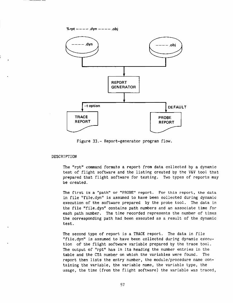
%rpt ---- .dyn ---- .obj
REPORT r-l GENERATOR
I -t option
TRACE REPORT
DEFAULT
PROBE REPORT
F i g u r e 33.- Repor t -genera tor program flow.
DESCRIPTION
The "rpt l ' command formats a r e p o r t from data collected by a dynamic t e s t of f l i g h t software and t h e l i s t i n g created by t h e V&V t o o l t h a t p repa red t h a t f l i g h t software for t e s t i n g . Two t y p e s o f r e p o r t s may be created.
The f i r s t is a ''path" or "PROBE" report . For this report, the data i n f i l e " f i l e . d y n " is assumed t o have been collected d u r i n g dynamic e x e c u t i o n of t h e software p repa red by the probe t o o l . The data i n t h e f i l e " f i l e .dyn" c o n t a i n s p a t h numbers and an associate time for each p a t h number. The time reco rded r e p r e s e n t s the number of times t h e co r re spond ing p a t h had been execu ted as a r e s u l t of t h e dynamic t e s t .
The second t y p e o f r e p o r t is a TRACE r e p o r t . The data i n f i l e " f i l e . d y n " is assumed t o have been c o l l e c t e d d u r i n g dynamic execu- t i o n The o u t p u t of " r p t " h a s i n its heading t h e number e n t r i e s i n t h e t a b l e and t h e CTA number on which t h e v a r i a b l e s were found. The r e p o r t t hen lists t h e e n t r y number, t h e module/procedure name con- t a i n i n g the v a r i a b l e , t h e v a r i a b l e name, t h e v a r i a b l e t y p e , t h e usage , t h e time (from t h e f l i g h t software) t h e v a r i a b l e was traced,
of t h e f l i g h t software v a r i a b l e p repa red by the trace too l .
57
and the value of the variable when the trace was encountered, see figure 27. to rpt in file ending 'I- .dyn"; e.g., "file.dyn".
The data file returned by dynamic execution must be input
Both reports require a file, "file.obj" in addition to the file "file.dyn". contains the load module listing for either the TRACE or PROBE flight-software load. Within "file.obj" is a table containing dynamic tool numbers which are associated with the numbers in the data file "file. dyn . "
"File.obj" is a listing file returned by the Univac and
Note that "file.dyn" and "file.obj" are unique files, are generally paired together and usually have unique names.
The following arguments are interpreted by rpt:
-t Format a TRACE report. a TRACE report. report.
Use of this option causes rpt to format The default is to format a path o r PROBE
Be sure to input the correct data file!
EXAMPLES
rpt -t test.dyn afor.obj
Format a TRACE report from dynamic data test.dyn and listing afar-obj.
rpt paths.dyn alat.obj
Format a path (PROBE) report from dynamic data paths.dyn and listing alat.obj.
CONSTRAINTS
The AED V&V tools impose certain restrictions on the size of the interface file, the command language, and the source text to be analyzed. Most of the limita- tions based on size are generous (e.g., the maximum number of nested IF statements is one hundred). The tools are capable of handling quite large source text files. However, an unusually large program may have to be processed by several successive executions, each operating on a separate file of modules.
58
Universal Constraints
The universal constraints are as follows:
At most 250 modules may use the same COMMON block
Maximum of 80 characters per source-card image read
The maximum number of DD-paths is 50.
The maximum number of statements on a single DD-path is 100.
The sizes of the two random files on logical unit 8 (LIBNEW) and logical unit 1 1 (LIBOLD) are established using an OPEN statement in tool subrou- tine INITIN. The current sizes are 500 records (of 300 words each).
Subroutine NITTOK of the tools uses an OPEN statement to establish two direct access scratch files, TOKFIL and LNKFIL, on logical units 21 and 22, respectively. Improper arguments can lead to excessive execution time for the tools.
Maximum of 250 tokens per statement.
Syntax Constraints
The following implementation constraints must be observed:
Each module placed on the same interface library must have a unique name.
If any errors are detected in the source, one or more statements may be flagged as not parsed.
Tool Deficiencies
The AED V&V tools were evaluated and tested under contract by Boeing Commercial Airplane Company. this User's Guide. complete for the current version of the AED V&V tools:
The final report is to be published and was not available for The following list (not ranked) of tool deficiencies is not
If a tool encounters "SYNTAX ERROR DUMP" during its lexical analysis of a module, a tool report is still generated but not accurate.
The PROBE tool does not check the path for branches if the branches occur to the right of an equal sign.
59
The PROBE tool does not generate the proper calling sequence for the dynamic routine DDPATH when processing multi-procedure --- multi-modules.
The COMMENT ASSERT* statement CANNOT be present in the source code when executing the TRACE tool.
COMMENT INPUT* and COMMENT OUTPUT* statements are permitted in the source code when executing the ASSERT tool.
UNITS tool cannot properly process units in expressions within an argument list.
UNITS tool has difficulty processing units such as acceleration (feet/sec**2 o r feet/sec/sec) in expressions.
A maximum of 30 logical assertions violations can be accumulated during dynamic execution.
REACHING SET control file requires the input to be in a specific type format. It must be of the FORTRAN format 215. The REACHING SET tool reads the starting statement line number and the ending statement line number before the tool starts reaching analysis.
Multimodules are handled differently by the CALLING TREE tool. The mod- ules MUST be CONCATENATED sequentially then given to the CALLING TREE for processing. The Calling Tree interface handler takes care of concatenation.
Dynamic tools ASSERT,TRACE, and PROBE require special loading procedures (refer to "Dynamic Tools" section fo r details).
SUMMARY OF AED V&V TOOL COMMANDS
A summary of commands is presented in the next two sections. In the first section, a summary of all the PDP-11/60 UNIX commands for all the tools is pre- sented. An example is given for a typical situation of one AED module being pro- cessed.
In the second section, a summary of all Univac commands necessary to execute I each tool is presented. Again, the typical situation is of one AED module being i processed.
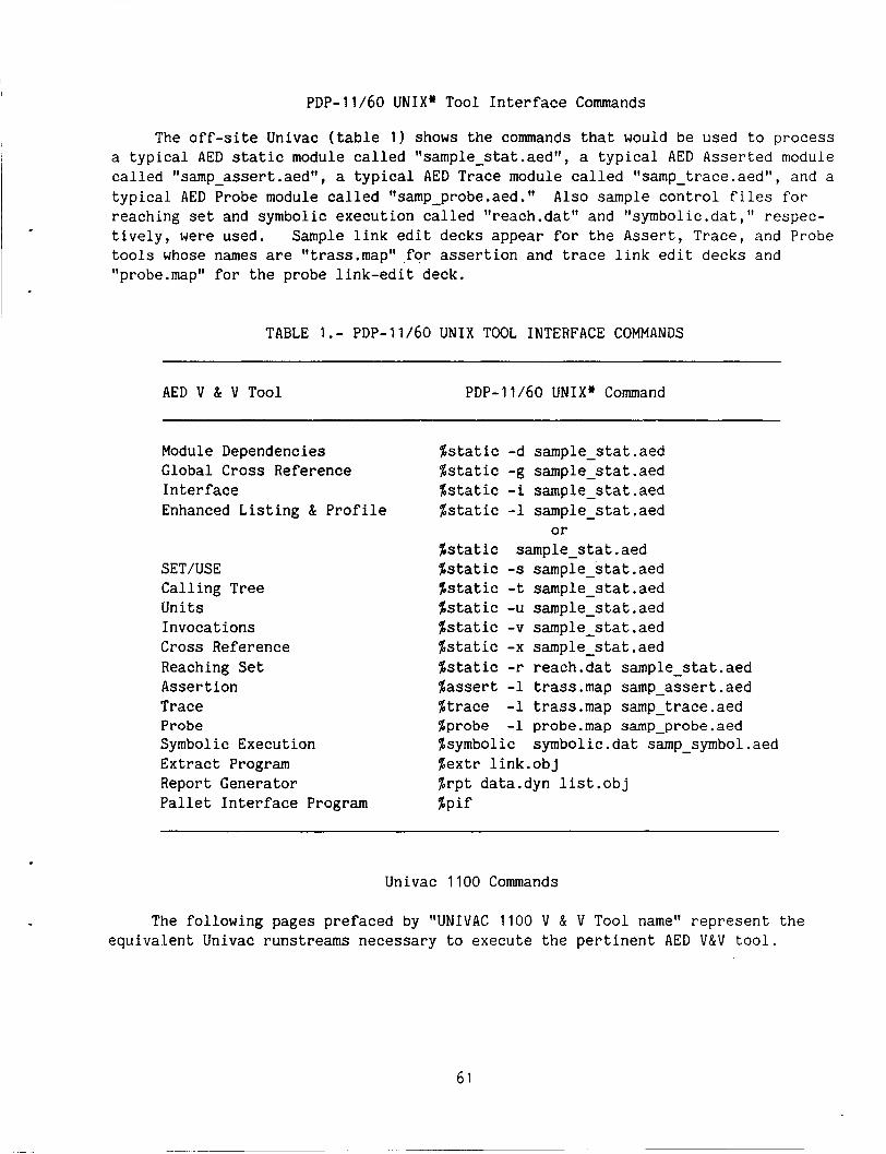
PDP-11/60 UNIX* Tool Interface Commands
The off-site Univac (table 1) shows the commands that would be used to process a typical AED static module called "sample_stat.aedtt, a typical AED Asserted module called "samp - assert.aed", a typical AED Trace module called "samp-trace.aed", and a typical AED Probe module called "samp_probe.aed." reaching set and symbolic execution called "reach.dat" and "symbolic.dat," respec- tively, were used. Sample link edit decks appear for the Assert, Trace, and Probe tools whose names are "trass.maptt ,for assertion and trace link edit decks and "probe.map" for the probe link-edit deck.
Also sample control files for
TABLE 1.- PDP-11/60 UNIX TOOL INTERFACE COMMANDS
AED V & V Tool PDP-11/60 UNIX* Command
Module Dependencies Global Cross Reference Interface Enhanced Listing & Profile
SET/USE Calling Tree Units Invocations Cross Reference Reaching Set Assertion Trace Probe Symbolic Execution Extract Program Report Generator Pallet Interface Program
$static -d sample-stat.aed $static -g sample-stat.aed $static -i sample-stat.aed $static -1 sample-stat.aed
%static sample-stat.aed $static -s sample-stat.aed %static -t sample-stat.aed %static -u sample-stat.aed $static -v sample-stat.aed $static -x sample-stat.aed $static -r reach.dat sample - stat.aed %assert -1 trass.map samp-assert.aed $trace -1 trass.map samp-trace.aed %probe -1 probe.map sap-probe.aed %symbolic symbolic.dat samp-symbol.aed $extr 1ink.obj $rpt data.dyn 1ist.obj
or
%Pif
Univac 1100 Commands
The following pages prefaced by YJNIVAC 1100 V & V Tool name" represent the equivalent Univac runstreams necessary to execute the pertinent AED V&V tool.
61
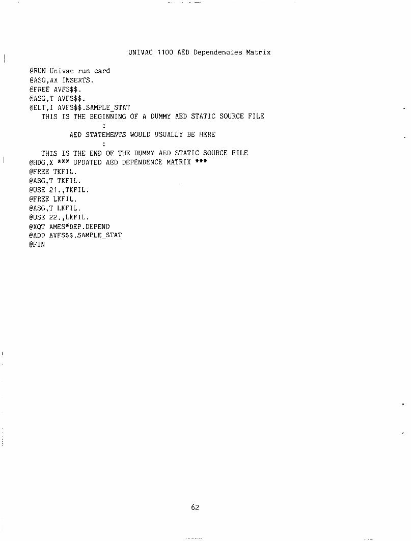
I UNIVAC 1100 AED Dependencies Matrix
@RUN Univac run card @ASG,AX INSERTS. @FREE AVFS$$. @ASG,T AVFS$$. @ELT , I AVFS$$ . SAMPLE-STAT
THIS IS THE BEGINNING OF A DUMMY AED STATIC SOURCE FILE
AED STATEMENTS WOULD USUALLY BE HERE
THIS IS THE END OF THE DUMMY AED STATIC SOURCE FILE i @HDG,X *** UPDATED AED DEPENDENCE MATRIX ***
@FREE TKFIL. @ASG,T TKFIL. @USE 21.,TKFIL. @FREE LKFIL. @ASG,T LKFIL. @USE 22.,LKFIL. @XQT AMES*DEP.DEPEND @ADD AVFS$$.SAMPLE-STAT @FIN
62
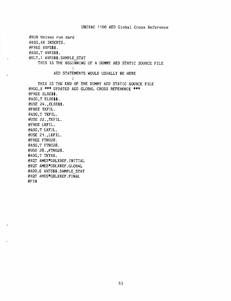
UNIVAC 1100 AED Global Cross Reference
@RUN Univac run card @ASG,AX INSERTS. @FREE AVFS$$. @ASG, T AVFS$$ . @ELT,I AVFS$$.SAMPLE STAT
THIS IS THE BEGINNING OF A DUMMY AED STATIC SOURCE FILE AED STATEMENTS WOULD USUALLY BE HERE
THIS IS THE END OF THE DUMMY AED STATIC SOURCE FILE @HDG,X *** UPDATED AED GLOBAL CROSS REFERENCE *** @FREE ELSE$$. @ASG,T ELSE$$. @USE 24.,ELSE$$. @FREE TKFIL. @ASG,T TKFIL. @USE 22.,TKFIL. @FREE LKFIL. @ASG,T LKFIL. @USE 21.,LKFIL. @FREE FTN028. @ASG,T FTN028. @USE 28.,FTN028. @ASG,T TKTAB. @XQT AMES*GBLXREF.INITIAL @XQT AMES*GBLXREF.GLOBAL @ADD, E AVFS$$ .SAMPLE STAT
@FIN @XQT AMES*GBLXREF .FINAL
63
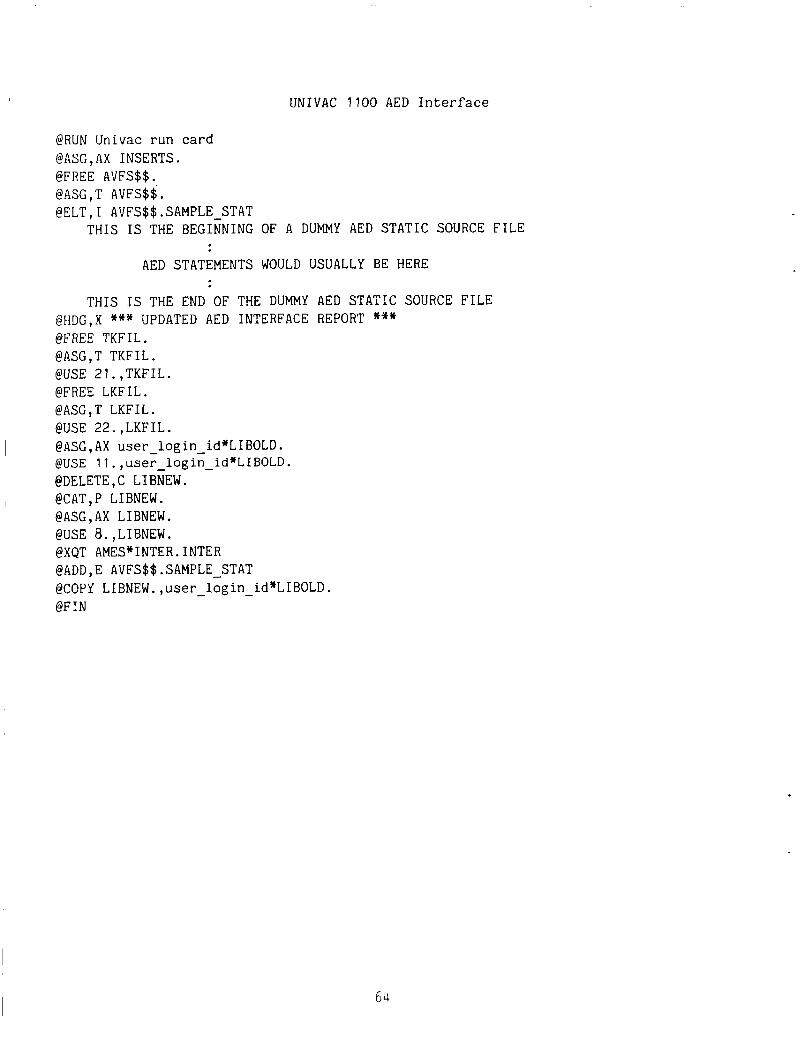
UNIVAC 1100 AED Interface
@RUN Univac run card @ASG,AX INSERTS. @FREE AVFS$$.
@ELT,I AVFS$$.SAMPLE-STAT @ASG , T AVFS$$ .
THIS IS THE BEGINNING OF A DUMMY AED STATIC SOURCE FILE
AED STATEMENTS WOULD USUALLY BE HERE
THIS IS THE END OF THE DUMMY AED STATIC SOURCE FILE @HDG,X *** UPDATED AED INTERFACE REPORT *** @FREE TKFIL. @ASG,T TKFIL. @USE 21.,TKFIL. @FREE LKFIL. @ASG,T LKFIL. @USE 22.,LKFIL. @ASG,AX user-login-id*LIBOLD. @USE Il.,user-login-id*LIBOLD. @DELETE,C LIBNEW. @CAT,P LIBNEW. @ASG,AX LIBNEW. @USE 8.,LIBNEW. @XQT AMES*INTER.INTER @ADD,E AVFS$$.SAMPLE STAT @COPY LIBNEW. ,user - login - id*LIBOLD. @FIN
64
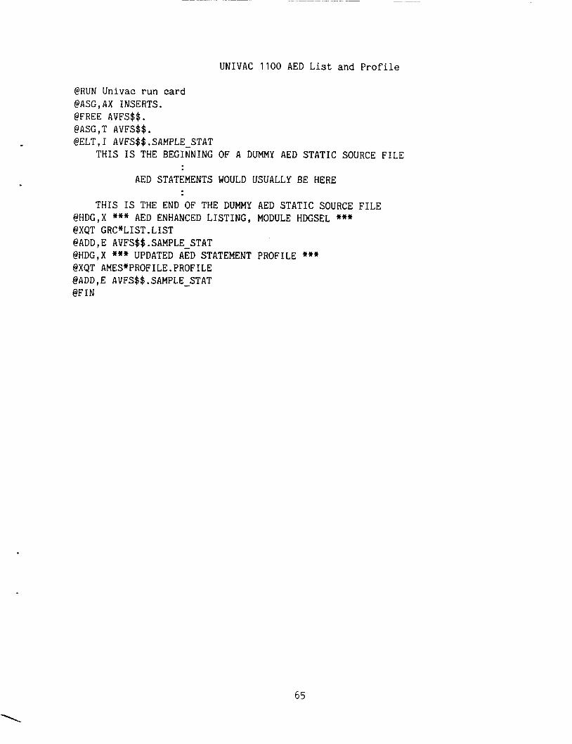
~ ~ ~ _ _ _ _ _ _ ~ ~~~~~ ~~~
UNIVAC 1100 AED List and Profile
@RUN Univac run card @ASG,AX INSERTS. @FREE AVFS$$. @ASG,T AVFS$$. @ELT, r AVFS$$. SAMPLE STAT
THIS IS THE BEGINNING OF A DUMMY AED STATIC SOURCE FILE AED STATEMENTS WOULD USUALLY BE HERE
THIS IS THE END OF THE DUMMY AED STATIC SOURCE FILE @HDG,X *** AED ENHANCED LISTING, MODULE HDGSEL *** @XQT GRC*LIST.LIST @ADD,E AVFS$$.SAMPLE STAT
@XQT AMES*PROFILE.PROFILE @ADD , E AVFS$$ .SAMPLE - STAT @FIN
@HDG,X *** UPDATED AED STATEMENT PROFILE ***
65
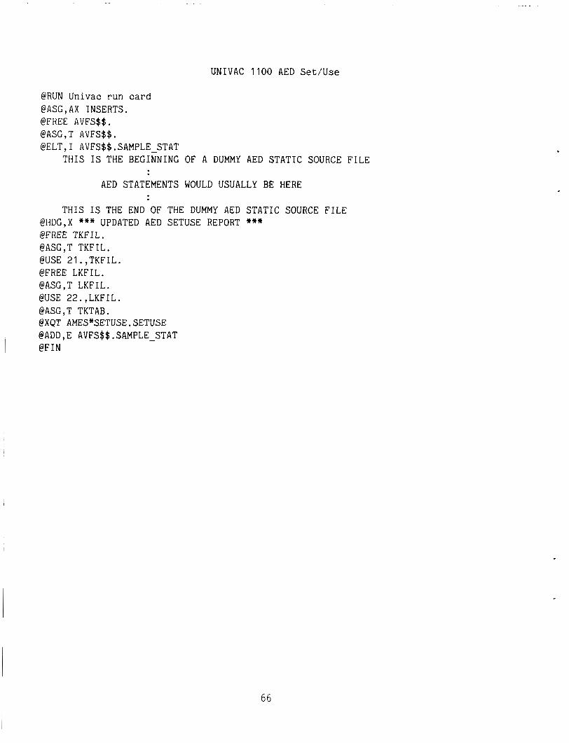
UNIVAC 1100 AED Set/Use
@RUN Univac run card @ASG,AX INSERTS. @FREE AVFS$$. @ASC,T AVFS$$. @ELT,I AVFS$$.SAMPLE-STAT
THIS IS THE BEGINNING OF A DUMMY AED STATIC SOURCE FILE
AED STATEMENTS WOULD USUALLY BE HERE
THIS IS THE END OF THE DUMMY AED STATIC SOURCE FILE @HDG,X *** UPDATED AED SETUSE REPORT *** @FREE TKFIL. @ASG,T TKFIL. @USE 21.,TKFIL. @FREE LKFIL. @ASG,T LKFIL. @USE 22.,LKFIL. @ASG,T TKTAB. @XQT AMES*SETUSE.SETUSE @ADD,E AVFS$$.SAMPLE STAT @FIN I -
66
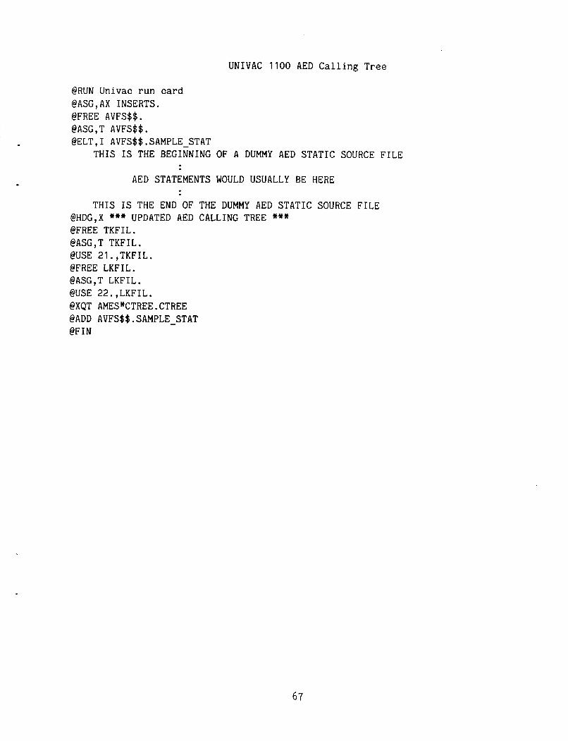
~ ~~ ~ ~ ~~~
UNIVAC 1100 AED Calling Tree
@RUN Univac run card @ASG,AX INSERTS. @FREE AVFS$$ . @ASG,T AVFS$$. @ELT, I AVFS$$ .SAMPLE STAT
THIS IS THE BEGINNING OF A DUMMY AED STATIC SOURCE FILE AED STATEMENTS WOULD USUALLY BE HERE
THIS IS THE END OF THE DUMMY AED STATIC SOURCE FILE @HDG,X *** UPDATED AED CALLING TREE *** @FREE TKFIL. @ASG,T TKFIL. @USE 21.,TKFIL. @FREE LKFIL. @ASG,T LKFIL. @USE 22.,LKFIL. @XQT AMES*CTREE.CTREE @ADD AVFS$$.SAMPLE-STAT @FIN
67
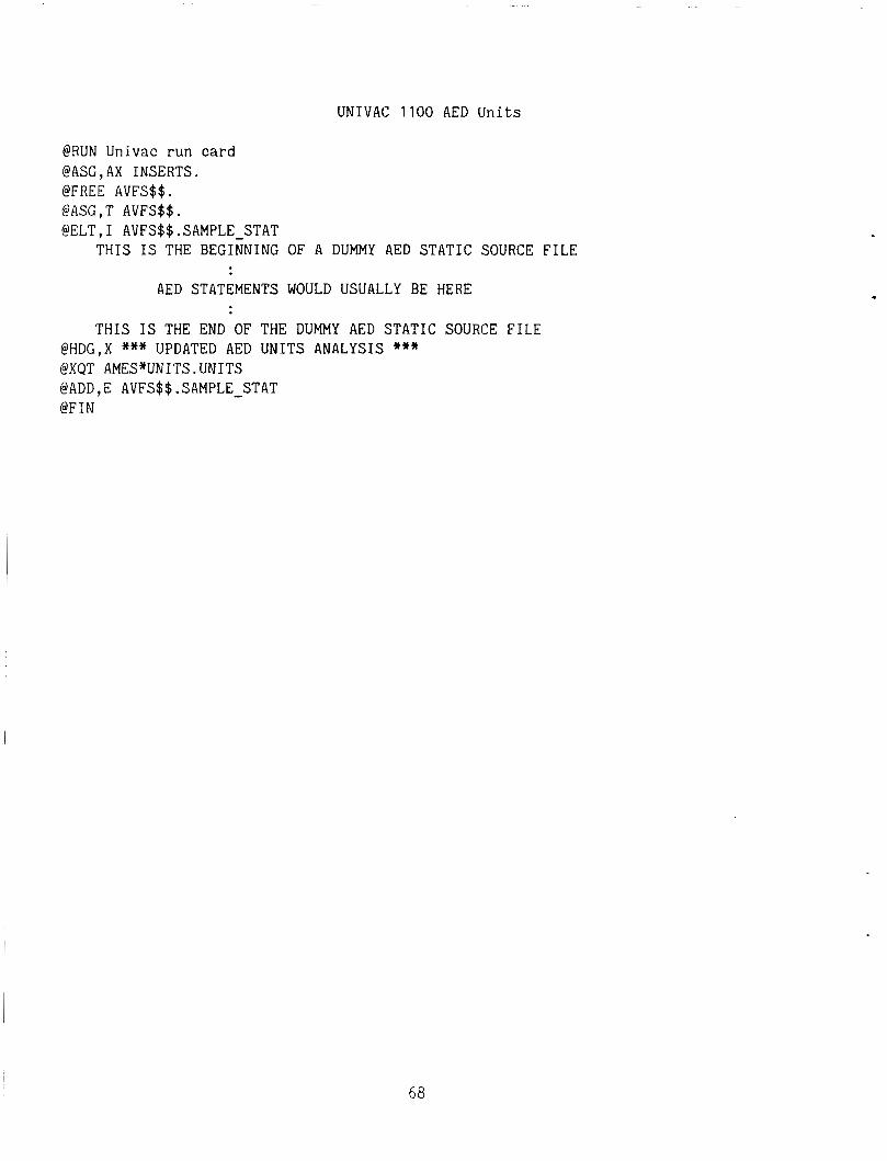
UNIVAC 1100 AED Units
@RUN Univac run card @ASG,AX INSERTS. @FREE AVFS$$. @ASG,T AVFS$$. @ELT,I AVFS$$.SAMPLE-STAT
THIS IS THE BEGINNING OF A DUMMY AED STATIC SOURCE FILE
AED STATEMENTS WOULD USUALLY BE HERE
THIS IS THE END OF THE DUMMY AED STATIC SOURCE FILE @HDG,X *** UPDATED AED UNITS ANALYSIS *** @XQT AMES*UNITS.UNITS @ADD,E AVFS$$.SAMPLE - STAT @FIN
68

UNIVAC 1100 AED Invocation
@RUN Univac run card @ASG,AX INSERTS. @FREE AVFS$$. @ A X , T AVFS$$ . @ELT,I AVFS$$.SAMPLE STAT
THIS IS THE BEGINNING OF A DUMMY AED STATIC SOURCE FILE AED STATEMENTS WOULD USUALLY BE HERE
THIS IS THE END OF THE DUMMY AED STATIC SOURCE FILE @HDG,X *** UPDATED AED INVOCATIONS REPORT *** @FREE TKFIL. @ASG,T TKFIL. @USE 21.,TKFIL. @FREE LKFIL. @ASG,T LKFIL. @USE 22.,LKFIL. @XQT AMES*INVOKE.INVOKE @ADD AVFS$$ .SAMPLE - STAT @FIN
69
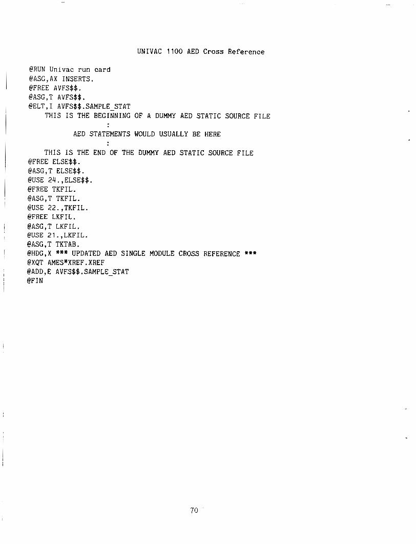
UNIVAC 1100 AED Cross Reference
@RUN Univac run card @ASG,AX INSERTS. @FREE AVFS$$. @ASG,T AVFS$$. @ELT,I AVFS$$.SAMPLE STAT
THIS IS THE BEGINNING OF A DUMMY AED STATIC SOURCE FILE AED STATEMENTS WOULD USUALLY BE HERE
THIS IS THE END OF THE DUMMY AED STATIC SOURCE FILE @FREE ELSE$$. @ASG,T ELSE$$. @USE 24.,ELSE$$. @FREE TKFIL. @ASG,T TKFIL. @USE 22.,TKFIL. @FREE LKFIL. @ASG,T LKFIL. @USE 21.,LKFIL. @ASG,T TKTAB. @HDG,X *** UPDATED AED SINGLE MODULE CROSS REFERENCE *** @XQT AMES*XREF.XREF @ADD, E AVFS$$ . SAMPLE-STAT @FIN
70
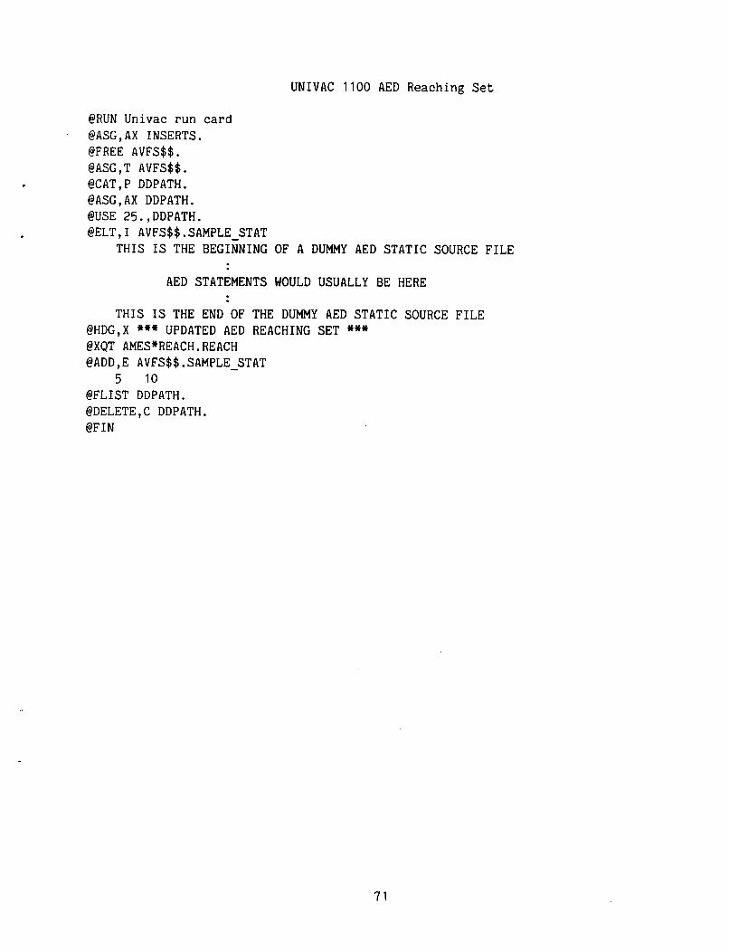
~
UNIVAC 1100 AED Reaching S e t
@RUN Univac run card @ASG,AX INSERTS. @FREE AVFS$$. @ASG,T AVFS$$. @CAT,P DDPATH. @ASG,AX DDPATH. @USE 25.,DDPATH. @ELT,I AVFS$$.SAMPLE STAT
THIS IS THE BEGINNING OF A DUMMY AED STATIC SOURCE FILE AED STATEMENTS WOULD USUALLY BE HERE
THIS IS THE END OF THE DUMMY AED STATIC SOURCE FILE @HDG,X *** UPDATED AED REACHING SET *** @XQT AMES*REACH.REACH @ADD,E AVFS$$.SAMPLE - STAT
5 10 @FLIST DDPATH. @DELETE,C DDPATH. @FIN
71
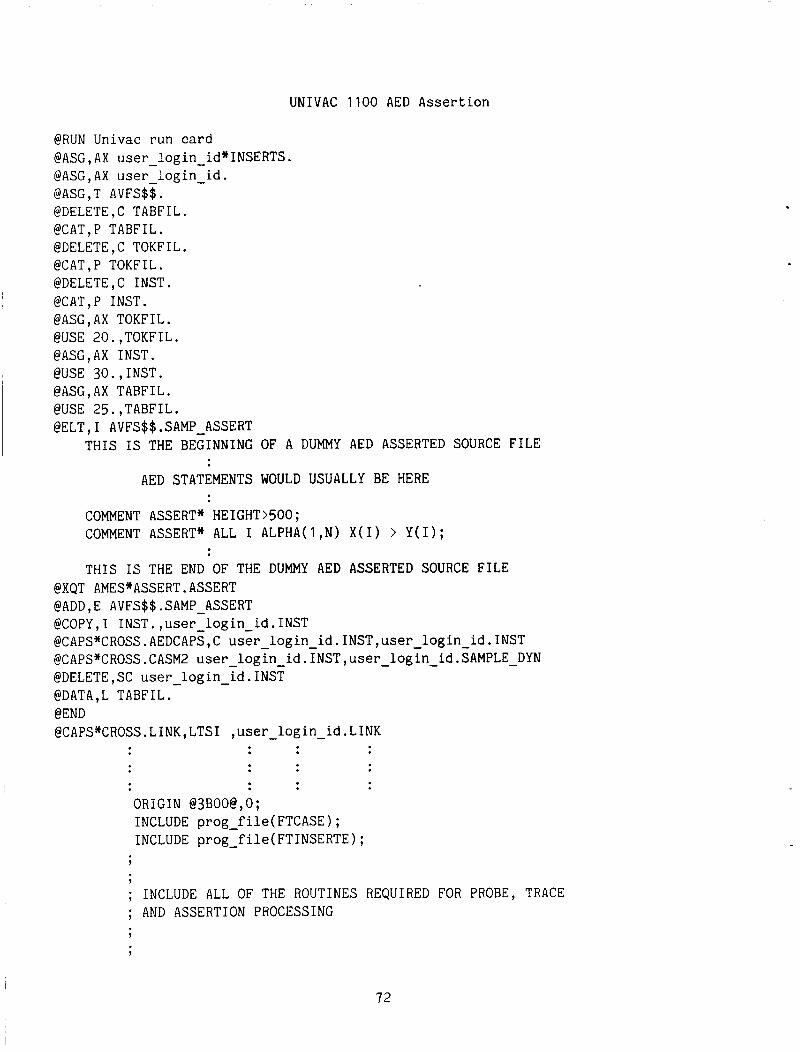
UNIVAC 1100 AED Assertion
@RUN Univac run card @ASG,AX user-login-id*INSERTS. @ASG,AX user-login-id. @ASG,T AVFS$$. @DELETE,C TABFIL. @CAT,P TABFIL. @DELETE,C TOKFIL. @CAT,P TOKFIL. @DELETE,C INST. @CAT,P INST. @ASG,AX TOKFIL. @USE 20.,TOKFIL. @ASC,AX INST. @USE 30.,INST. @ASG,AX TABFIL. @USE 25.,TABFIL. @ELT,I AVFS$$.SAMP-ASSERT
THIS IS THE BEGINNING OF A DUMMY AED ASSERTED SOURCE FILE
AED STATEMENTS WOULD USUALLY BE HERE
COMMENT ASSERT* HEIGHT>SOO; COMMENT ASSERT* ALL I ALPHA(1,N) X(1) > Y(1);
THIS IS THE END OF THE DUMMY AED ASSERTED SOURCE FILE @XQT AMES*ASSERT.ASSERT @ADD,E AVFS$$.SAMP-ASSERT @COPY,I INST.,user-login id.INST @CAPS*CROSS . AEDCAPS, C user-login-id . INST, user login id. INST @CAPS*CROSS. CASM2 user-login-id . INST, user-login - id .SAMPLE - DYN @DELETE,SC user - login - id.INST @DATA,L TABFIL. @END @CAPS*CROSS.LINK,LTSI ,user - login - id.LINK
ORIGIN @3BOO@,O; INCLUDE prog-f ile( FTCASE) ; INCLUDE prog-file( FTINSERTE) ;
7
9
; INCLUDE ALL OF THE ROUTINES REQUIRED FOR PROBE, TRACE ; AND ASSERTION PROCESSING 7
1
72
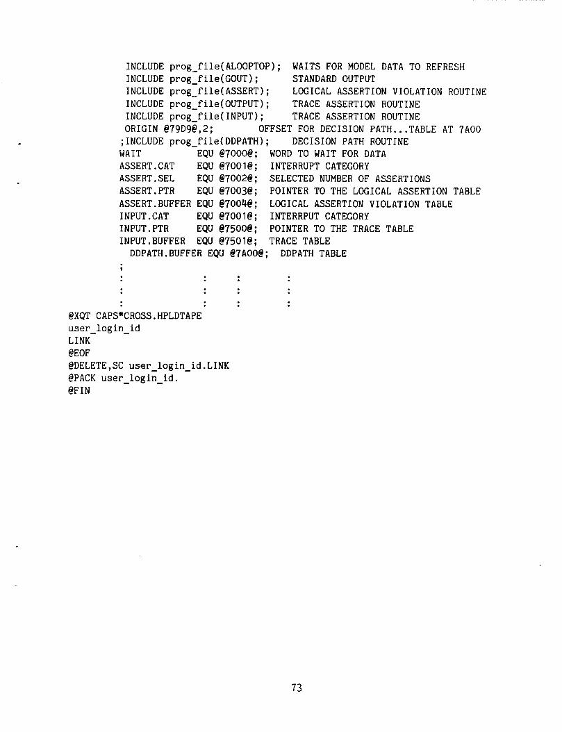
INCLUDE prog-file(ALOOPT0P); INCLUDE prog f ile(G0UT) ; INCLUDE prog-file( ASSERT) ; INCLUDE proglf ile( OUTPUT) ; INCLUDE prog file(1NPUT); ORIGIN @79D9@,2; ;INCLUDE prog-file(DDPATH); DECISION PATH ROUTINE WAIT EQU @7000@; WORD TO WAIT FOR DATA ASSERT.CAT EQU @7001@; INTERRUPT CATEGORY ASSERT.SEL EQU @7002@; SELECTED NUMBER OF ASSERTIONS ASSERT.PTR EQU @7003@; POINTER TO THE LOGICAL ASSERTION TABLE ASSERT.BUFFER EQU @7004@; INPUT. CAT EQU @7001@; INTERRPUT CATEGORY INPUT. PTR EQU @7500@; POINTER TO THE TRACE TABLE 1NPUT.BUFFER EQU @7501@; TRACE TABLE
WAITS FOR MODEL DATA TO REFRESH STANDARD OUTPUT LOGICAL ASSERTION VIOLATION ROUTINE TRACE ASSERTION ROUTINE TRACE ASSERTION ROUTINE
OFFSET FOR DECISION PATH ... TABLE AT 7A00
LOGICAL ASSERTION VIOLATION TABLE
DDPATH.BUFFER EQU @7A00@; DDPATH TABLE ?
@XQT CAPS*CROSS.HPLDTAPE user-login - id LINK @EOF @DELETE,SC user-login-id.LINK @PACK user-login - id. @FIN
73
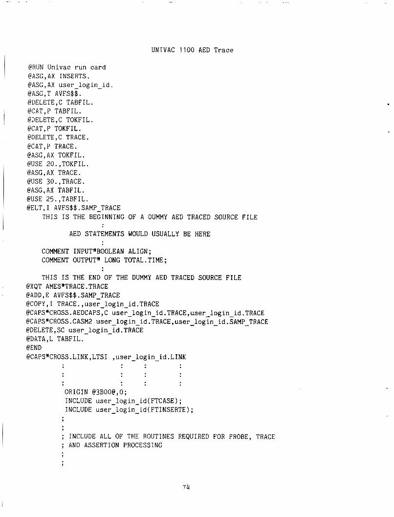
UNIVAC 1100 AED Trace
@RUN Univac run card @ASC,AX INSERTS. @ASG,AX user-login - id. @ASG,T AVFS$$. @DELETE,C TABFIL. @CAT,P TABFIL. @DELETE,C TOKFIL. @CAT,P TOKFIL. @DELETE,C TRACE. @CAT,P TRACE. @ASG,AX TOKFIL. @USE 20.,TOKFIL. @ASG,AX TRACE. @USE 30.,TRACE. @ASC,AX TABFIL. @USE 25.,TABFIL. @ELT,I AVFS$$.SAMP-TRACE
THIS IS THE BEGINNING OF A DUMMY AED TRACED SOURCE FILE
AED STATEMENTS WOULD USUALLY BE HERE
COMMENT INPUT*BOOLEAN ALIGN; COMMENT OUTPUT* LONG TOTAL.TIME;
THIS IS THE END OF THE DUMMY AED TRACED SOURCE FILE @XQT AMES*TRACE.TRACE @ADD,E AVFS$$.SAMP TRACE @COPY, I TRACE. ,user login id. TRACE @CAPS*CROSS . AEDCAPSTC useylogin-id .TRACE ,user login id .TRACE @CAPS*CROSS . CASM2 user-login-id .TRACE, user-login-id . :AMP-TRACE @DELETE,SC user-login - id.TRACE @DATA,L TABFIL. @END @CAPS*CROSS.LINK,LTSI ,user-login-id.LINK
ORIGIN @3BOO@,O; INCLUDE user-login-id(FTCASE); INCLUDE user-login-id(FT1NSERTE);
?
; INCLUDE ALL OF THE ROUTINES REQUIRED FOR PROBE, TRACE ; AND ASSERTION PROCESSING
74
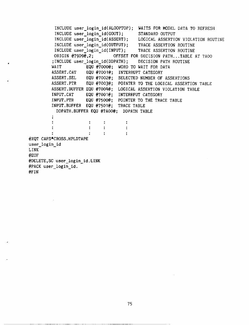
INCLUDE user - login - id(ALOOPT0P); WAITS FOR MODEL DATA TO REFRESH INCLUDE user login id(C0UT); INCLUDE user-login-id( - ASSERT) ; INCLUDE user-login - id(0UTPUT) ; INCLUDE user-login - id( INPUT) ; ORIGIN @79D9@,2; OFFSET ;INCLUDE user - login id(DDPATH); WAIT EQU @?OOO@ ; WORD
STANDARD OUTPUT LOGICAL ASSERTION VIOLATION ROUTINE TRACE ASSERTION ROUTINE TRACE ASSERTION ROUTINE
DECISION PATH ROUTINE FOR DECISION PATH ... TABLE AT 7A00 TO WAIT FOR DATA I
ASSERT.CAT EQU @7001@; INTERRUPT CATEGORY ASSERT.SEL EQU @7002@; SELECTED NUMBER OF ASSERTIONS ASSERT.PTR EQU @7003@; POINTER TO THE LOGICAL ASSERTION TABLE ASSERT.BUFFER EQU @7004@; 1NPUT.CAT EQU @7001@; INTERRPUT CATEGORY INPUT. PTR EQU @7500@; POINTER TO THE TRACE TABLE 1NPUT.BUFFER EQU @7501@; TRACE TABLE
LOGICAL ASSERTION VIOLATION TABLE
DDPATH.BUFFER EQU @7A00@; DDPATH TABLE
@XQT CAPS*CROSS.HPLDTAPE user-login-id LINK @EOF @DELETE,SC user login - id.LINK @PACK user-login - id. @FIN
75
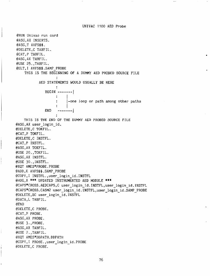
UNIVAC 1100 AED Probe
@RUN Univac run card @ASG,AX INSERTS. @ASG,T AVFS$$. @DELETE,C TABFIL. @CAT,P TABFIL. @ASG,AX TABFIL. @USE 25.,TABFIL. @ELT,I AVFS$$.SAMP-PROBE
THIS IS THE BEGINNING OF A DUMMY AED PROBED SOURCE FILE
AED STATEMENTS WOULD USUALLY BE HERE
I BEGIN ------- : I
: I : I-one loop or path among other paths
I END --_----
THIS IS THE END OF THE DUMMY AED PROBED SOURCE FILE @ASG,AX user-login - i d . @DELETE,C TOKFIL. @CAT,P TOKFIL. @DELETE,C INSTFL. @CAT,P INSTFL. @ASG,AX TOKFIL. @USE 20.,TOKFIL. @ASG,AX INSTFL. @USE 30.,INSTFL. @XQT AMES*PROBE.PROBE @ADD,E AVFS$$.SAMP PROBE @COPY, I INSTFL. ,user-login-id. INSTFL @HDG,X *** UPDATED INSTRUMENTED AED MODULE *** @CAPS*CROSS.AEDCAPS,C user-login-id.INSTFL,user-login-id.INSTFL @CAPSnCROSS.CASM2 user-login-id.INSTFL,user - login - id.SAMP - PROBE @DELETE,SC user-login-id.INSTFL @DATA,L TABFIL. @END @DELETE,C PROBE. @CAT,P PROBE. @ASG,AX PROBE. @USE 3.,PROBE. @ASG,AX TABFIL. @USE 2.,TABFIL. @XQT AMES*DDPATH.DDPATH @COPY,I PROBE.,user-login - id.PROBE @DELETE,C PROBE.
76
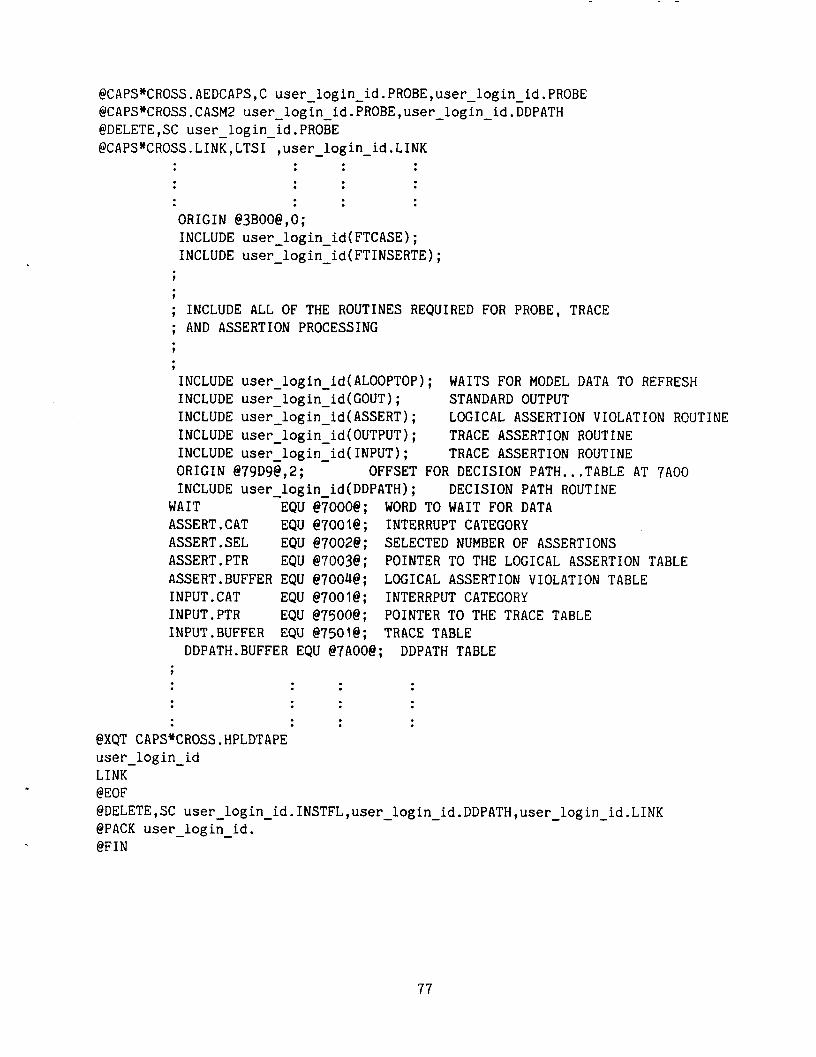
@CAPS*CROSS.AEDCAPS,C user login-id.PROBE,user-login id.PROBE @CAPS*CROSS . CASM2 user-login id. PROBE, user-login-id .EDPATH @DELETE ,SC user login id. PROBE @CAPS*CROSS. LINK, LTSI-,user - login-id. LINK
ORIGIN @3BOO@,O; INCLUDE user login-id(FTCASE) ; INCLUDE user-login-id(FT1NSERTE) - ;
9
9
; INCLUDE ALL OF THE ROUTINES REQUIRED FOR PROBE, TRACE ; AND ASSERTION PROCESSING 9
7
INCLUDE user-login-id(ALOOPT0P); INCLUDE user-login-id(C0UT); STANDARD OUTPUT INCLUDE user-login-id(ASSERT); INCLUDE user login - id(0UTPUT); INCLUDE user-login - id( INPUT) ; ORIGIN @79D9@,2; INCLUDE user - login id(DDPATH);
WAITS FOR MODEL DATA TO REFRESH
LOGICAL ASSERTION VIOLATION ROUTINE TRACE ASSERTION ROUTINE TRACE ASSERTION ROUTINE
OFFSET FOR DECISION PATH ... TABLE AT "A00 DECISION PATH ROUTINE
WAIT EQU @7000@; WORD TO WAIT FOR DATA ASSERT.CAT EQU @7001@; INTERRUPT CATEGORY ASSERT.SEL EQU @7002@; SELECTED NUMBER OF ASSERTIONS ASSERT.PTR EQU @7003@; POINTER TO THE LOGICAL ASSERTION TABLE ASSERT.BUFFER EQU @7004@; INPUT. CAT EQU @7001@; INTERRPUT CATEGORY INPUT. PTR EQU @7500@; POINTER TO THE TRACE TABLE 1NPUT.BUFFER EQU @7501@; TRACE TABLE
LOGICAL ASSERTION VIOLATION TABLE
DDPATH.BUFFER EQU @7A00@; DDPATH TABLE ?
@XQT CAPS*CROSS.HPLDTAPE user-login - id LINK @EOF @DELETE,SC user-login-id.INSTFL,user-login - id.DDPATH,user - l og in - id.LINK @PACK user - login - id. @FIN
77
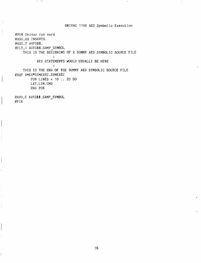
@RUN Univac run card @ASG,AX INSERTS. @ASG , T AVFS$$ . @ELT,I AVFS$$.SAMP-SYMBOL
THIS IS THE BEGINNING
AED STATEMENTS
UNIVAC 1100 AED Symbolic Execution
OF A DUMMY AED SYMBOLIC SOURCE FILE
WOULD USUALLY BE HERE
THIS IS THE END OF THE DUMMY AED SYMBOLIC SOURCE FILE @XQT AMES*SYMEXEC.SYMEXEC
FOR LINES = 10 .. 20 DO LAT.LIM.CMD END FOR
@ADD,E AVFS$$.SAMP-SYMBOL @FIN
78
APPENDIX A
V&V TOOL DEVELOPMENT COMPUTER
The software verification and validation tools for the DFCSVL were developed on The software tools were coded in IFTRAN," a preprocessor f o r FORTRAN, a VAX 11/780.
featuring structured language capability. Once the IFTRAN source code is processed and the FORTRAN source code created, the FORTRAN source code is passed to the FORTRAN compiler for compiling. Unfortunately, comments that occurred in the struc- tured code are not included in the FORTRAN source code so very little in-code docu- mentation is available at the FORTRAN source level. The FORTRAN source code of the V&V tools was provided under contract, therefore, any modification o r maintenance of the V&V tool software must be performed by the developer of the tools (ref. 1 ) .
Preliminary testing of the tools occurred on the VAX. However, since there are differences between the VAX and the Univac 1100, especially in memory allocation and disk usage, care must be used in rehosting the tools onto the Univac 1100.
"IFTRAN is a product of General Research Corporation.
79
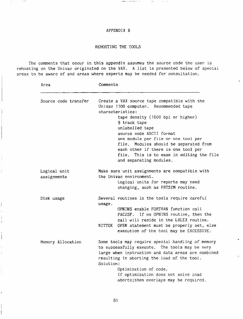
APPENDIX B
REHOSTING THE TOOLS
The comments that occur in this appendix assumes the source code the user is rehosting on the Univac originated on the VAX. A list is presented below of special areas to be aware of and areas where experts may be needed for consultation.
Area Comments
Source code transfer Create a VAX source tape compatible with the Univac 1100 computer. Recommended tape characteristics:
tape density (1600 bpi or higher) 9 track tape unlabelled tape source code ASCII format one module per f i l e or one too l per file. Modules should be separated from each other if there is one tool per file. This is to ease in editing the file and separating modules.
Logical unit assignments
Disk usage
Make sure unit assignments are compatible with the Univac environment.
Logical units for reports may need changing, such as PRTSYM routine.
Several routines in the tools require careful usage.
OPNINS enable FORTRAN function call FAC2SF. If no OPNINS routine, then the call will reside in the LRLEX routine.
execution of the tool may be EXCESSIVE. NITTOK OPEN statement must be properly set, else
Memory Allocation Some tools may require special handling of memory to successfully execute. The tools may be very large when instruction and data areas are combined resulting in aborting the load of the t o o l . Solution :
Optimization of code. If optimization does not solve load aborts;then overlays may be required.
Dynamic AED V&V tool routines
ASSERT, PROBE and TRACE tools require and build dynamic AED V & V tool routines. These routines need to be compiled and assembled by the AED processors so that the object codes will be available for the link loader. The list below provides information regarding these routines.
Subroutine Comments
DDPATH
1NPUT.TRACE
0UTPUT.TRACE
ASSERT.FALSE
GOUT
Generated by the PROBE tool.
AED V&V TRACE tool routine. See figure B1.
AED V&V TRACE tool routine. See figure B2.
AED V&V ASSERTION tool routine. See figure B3.
AED Standard output routine. DDPATH references GOUT. See figure B4.
81
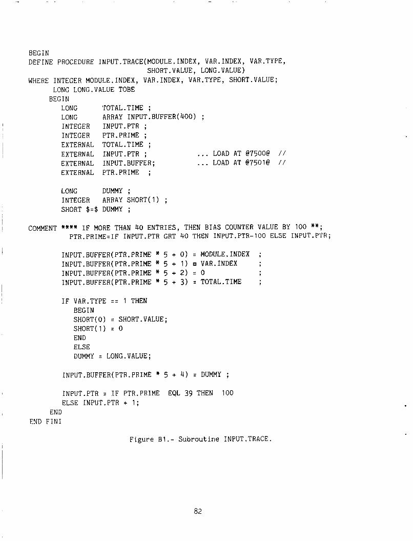
BEGIN DEFINE PROCEDURE INPUT.TRACE(MODULE.INDEX, VAR.INDEX, VAR.TYPE,
SHORT.VALUE, LONG.VALUE) WHERE INTEGER MODULE.INDEX, VAR.INDEX, VAR.TYPE, SHORT.VALUE;
LONG LONG.VALUE TOBE BEG IN
LONG TOTAL.TIME ; LONG ARRAY INPUT. BUFFER( 400) ; INTEGER 1NPUT.PTR ; INTEGER PTR.PRIME ; EXTERNAL TOTAL-TIME ; EXTERNAL 1NPUT.PTR ; EXTERNAL 1NPUT.BUFFER; EXTERNAL PTR.PRIME ;
... LOAD AT @7500@ / /
... LOAD AT @7501@ / /
LONG DUMMY ; INTEGER ARRAY SHORT(1) ; SHORT $=$ DUMMY ;
I
I COMMENT **** IF MORE THAN 40 ENTRIES, THEN BIAS COUNTER VALUE BY 100 **; PTR.PRIME=IF 1NPUT.PTR GRT 40 THEN 1NPUT.PTR-100 ELSE 1NPUT.PTR;
INPUT.BUFFER(PTR.PRIME * 5 + 0) = MODULE.INDEX ; INPUT.BUFFER(PTR.PRIME * 5 + 1) VAR.INDEX 9
INPUT.BUFFER(PTR.PRIME * 5 + 2) = 0 9
INPUT.BUFFER(PTR.PRIME * 5 + 3 ) = TOTAL.TIME ;
IF VAR.TYPE = = 1 THEN BEGIN SHORT(0) = SHORT.VALUE; SHORT(1) = 0 END ELSE DUMMY = LONG.VALUE;
INPUT.BUFFER(PTR,PRIME * 5 + 4 ) = DUMMY ;
1NPUT.PTR = IF PTR.PRIME EQL 39 THEN 100 ELSE 1NPUT.PTR + 1 ;
END END FIN1
Figure B1.- Subroutine 1NPUT.TRACE.
82
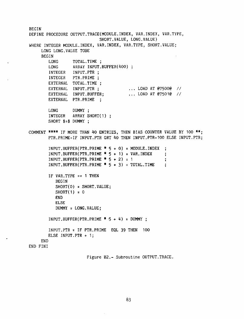
BEGIN DEFINE PROCEDURE OUTPUT.TRACE(MODULE.INDEX, VAR.INDEX, VAR.TYPE,
WHERE INTEGER MODULE.INDEX, VAR.INDEX, VAR.TYPE, SHORT.VALUE; SHORT.VALUE, LONG.VALUE)
LONG LONG.VALUE TOBE BEGIN
LONG TOTAL.TIME ; LONG ARRAY INPUT.BUFFER(400) ; INTEGER 1NPUT.PTR ; INTEGER PTR.PRIME ; EXTERNAL TOTAL.TIME ; EXTERNAL 1NPUT.PTR ; ... LOAD AT @7500@ / / EXTERNAL 1NPUT.BUFFER; ... LOAD AT @7501@ / / EXTERNAL PTR.PRIME ;
LONG DUMMY ; INTEGER ARRAY SHORT(1) ; SHORT $=$ DUMMY ;
COMMENT **** IF MORE THAN 40 ENTRIES, THEN BIAS COUNTER VALUE BY 100 **; PTR.PRIME=IF 1NPUT.PTR CRT 40 THEN 1NPUT.PTR-100 ELSE 1NPUT.PTR;
INPUT.BUFFER(PTR.PRIME * 5 + 0) = MODULE.INDEX ; INPUT.BUFFER(PTR.PRIME * 5 + 1) = VAR.INDEX 9
INPUT.BUFFER(PTR.PRIME * 5 + 2) = 1 9
INPUT.BUFFER(PTR.PRIME * 5 + 3 ) = TOTAL.TIME ;
IF VAR.TYPE == 1 THEN BEGIN SHORT(0) = SHORT.VALUE; SHORT(1) = 0 END ELSE DUMMY = LONG.VALUE;
INPUT.BUFFER(PTR.PRIME * 5 + 4) = DUMMY ;
1NPUT.PTR = IF PTR.PRIME EQL 39 THEN 100 ELSE 1NPUT.PTR + 1 ;
END END FIN1
Figure B2.- Subroutine 0UTPUT.TRACE.
83
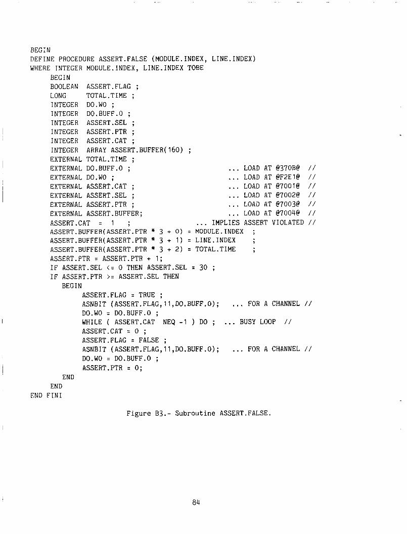
BEGIN DEFINE PROCEDURE ASSERT.FALSE (MODULE.INDEX, LINE.INDEX) WHERE INTEGER MODULE.INDEX, LINE.INDEX TOBE
BEGIN BOOLEAN ASSERT.FLAC ; LONG TOTAL.TIME ; INTEGER DO.WO ; INTEGER DO.BUFF.0 ; INTEGER ASSERT.SEL ; INTEGER ASSERT.PTR ; INTEGER ASSERT.CAT ; INTEGER ARRAY ASSERT.BUFFER(160) ; EXTERNAL TOTAL .TIME ; EXTERNAL DO.BUFF.0 ; ... LOAD AT @370B@ / / EXTERNAL DO.WO ; ... LOAD AT @F2E1@ / / EXTERNAL ASSERT.CAT ; ... LOAD AT @7001@ / / EXTERNAL ASSERT.SEL ; ... LOAD AT @7002@ / / EXTERNAL ASSERT.PTR ; ... LOAD AT @7003@ / / EXTERNAL ASSERT.BUFFER; ... LOAD AT @7004@ / / ASSERT.CAT = 1 ; ... IMPLIES ASSERT VIOLATED / / ASSERT.BUFFER(ASSERT.PTR * 3 + 0) = MODULE.INDEX ; ASSERT.BUFFER(ASSERT.PTR * 3 + 1 ) = LINE.INDEX ; ASSERT.BUFFER(ASSERT.PTR * 3 + 2) = TOTAL.TIME ; ASSERT.PTR = ASSERT.PTR + 1; IF ASSERT.SEL < = 0 THEN ASSERT.SEL = 30 ; IF ASSERT.PTR >= ASSERT.SEL THEN
BEGIN ASSERT.FLAG = TRUE ; ASNBIT (ASSERT.FLAG,ll,DO.BUFF.O); ... FOR A CHANNEL // DO.WO = DO.BUFF.0 ;
ASSERT.CAT = 0 ; ASSERT.FLAG = FALSE ; ASNBIT (ASSERT.FLAG,ll,DO.BUFF.O); ... FOR A CHANNEL / / DO.WO = DO.BUFF.0 ; ASSERT.PTR = 0 ;
WHILE ( ASSERT.CAT NEQ -1 ) DO ; ... BUSY LOOP / /
END END
END FIN1
Figure B3.- Subroutine ASSERT.FALSE.
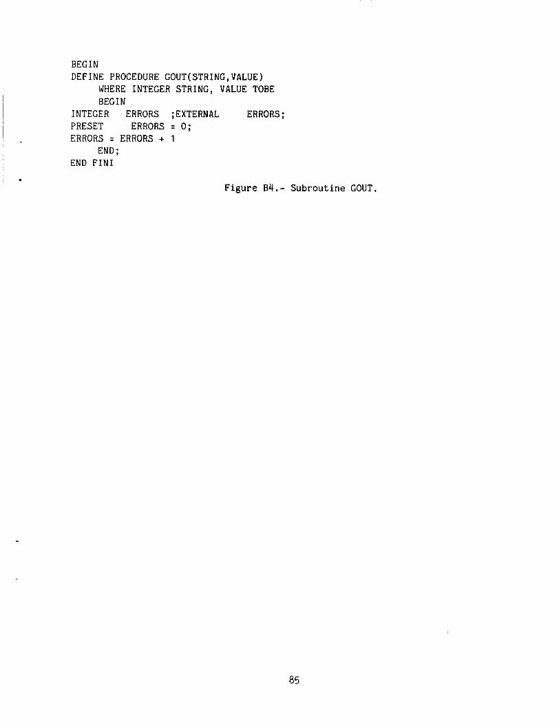
.
BEGIN DEFINE PROCEDURE GOUT(STRING,VALUE)
WHERE INTEGER STRING, VALUE TOBE BEG IN
INTEGER ERRORS ;EXTERNAL ERRORS ; PRESET ERRORS = 0; ERRORS = ERRORS + 1
END FIN1 END ;
Figure B4.- Subroutine GOUT.
85
APPENDIX C
PDP-11/60 INTERFACE HANDLERS
The PDP-11/60 Interface Handlers are a series of UNIX shell programs which make the utilization of the V&V tools "user friendly". These Interface Handlers help the user to prepare the Univac run-stream for a particular tool in the proper sequence, contents, and options of the Univac control commands. Consequently, the user needs to become familiar with the UNIX commands and the V&V tool capabilities.
The following information in this appendix is intended for the person who is establishing the V&V tool capability on their environment computer. the Interface Handlers are written in C programming language and under the source code control system as a means of maintaining source code configuration control. Since most of the source code for these handlers is relatively long, source listings are not included in this document. Source code listings can be requested from the author. A flow diagram of a handler is presented in figure C1.
The source for
86
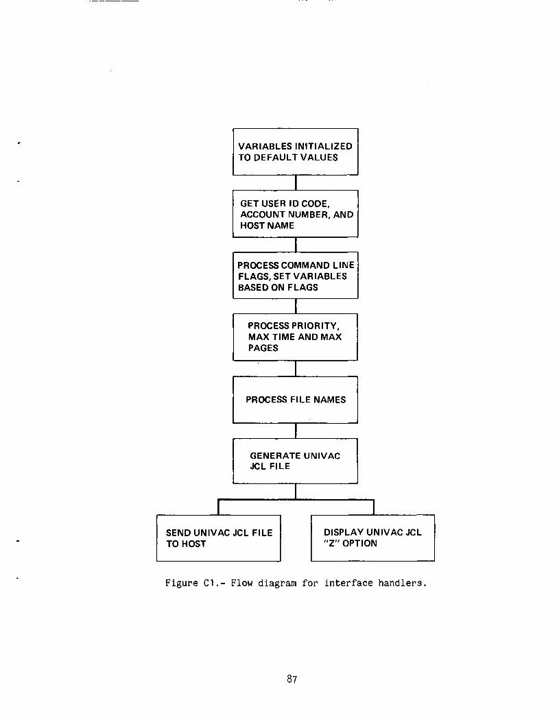
VARIABLES INITIALIZED TO DEFAULT VALUES
I GET USER I D CODE, ACCOUNT NUMBER, AND HOST NAME
I
PROCESS COMMAND LINE FLAGS, SET VARIABLES BASED ON FLAGS
PROCESS PRIORITY, MAX TIME AND MAX PAGES
PROCESS FILE NAMES LJ GENERATE UNIVAC I JCL FILE
SEND UNIVAC JCL FILE DISPLAY UNIVAC JCL "Z" OPTION
I J I I
Figure C1.- Flow diagram for i n t e r f a c e h a n d l e r s .
87
REFERENCES
1 . Saib, S. H.: Automated Verification of Flight Software - User's Manual. NASA CR-166346, 1982
2 . de Feo, P . ; Doane, D.; and Saito,J.: An Integrated User-Oriented Laboratory for Verification of Digital Flight Control Systems--Features and Capabilities. NASA TM 84276, 1982.
3. McLees, R . E . : Analysis of Verification Tools for Digital Flight Control Sys- tems (DFCS) Software. NASA CR- 17739 1 , Feb. 1986.
88
1. Report No. NASA TM 88313
3. Recipient's Catalog No. 2. Governnwnt h i o n No.
5. Report Date January 1987
, 9. Performing Organization Name and Address
Ames Research Center Moffett Field, CA 94035
12. Sponsoring Agency Name and Address
National Aeronautics and Space Administration Washington, DC 20546
6. Performing Organization Code
10. Work Unit No.
11. Contract or Grant No.
13. Type of Report and Period Covered
Technical Memorandum 14. Sponsoring Agency Code
505-66-2 1
8. Performing Orgmnization Report No.
A-86 28 2
Unclassified Unclassified 93 A05
~ ~~~
16 Abstract
The user's guide of verification and validation (V&V) tools for the Automated-Engineering-Design (AED) language is specifically written to update the information found in several documents pertaining to the auto- mated verification of flight software tools. The intent of this document is to provide, in one document, all the information necessary to adequately prepare a run to use thc AED V&V tools. FORTRAN V&V tools since they were not updated and are not currently active. Additionally, this document contains the current descriptions of the AED V&V tools and provides information to augment the NASA TM 84276 entitled "An Integrated User-Oriented Laboratory for Verification of Digital-Flight- Control Systems--Features and Capabilities."
The AED V&V tools are accessed from the digital-flight-control-systems verification laboratory (DFCSVL) via a PDP-11/60 digital computer. The AED V&V tool-interface handlers on the PDP-11/60 generate a Univac run stream which is transmitted to the Univac via a Remote Job Entry (RJE) link. Job execution takes place on the Univac 1100 and the j ob output is trans- mitted back to the DFCSVL and stored as a PDP-11/60 printfile.
No attempt is made to discuss the
7. Key Words (Suggcrted by Author(s)J
Verification of digital flight control system
Flight computer AED computer language
9. Security aaoif. (of this report) I 20. Security classif. ( 8
18. Distribution Statement
Unclassified - Unlimited
Star Category: 08
1 21. NO. of Pages ' this page) I 22. Rice'
'For sale by the National Technical Information Service. Springfield, Virginia 22161