Embed Size (px)
Citation preview

SERVICE MANUALVolume 1 1st Edition
DIGITAL HD VIDEOCASSETTE RECORDER
HVR-1500ANALOG INPUT BOARDHVBK-1505
HVR-1500
! WARNINGThis manual is intended for qualified service personnel only.To reduce the risk of electric shock, fire or injury, do not perform any servicing other than thatcontained in the operating instructions unless you are qualified to do so. Refer all servicing toqualified service personnel.
! WARNUNGDie Anleitung ist nur für qualifiziertes Fachpersonal bestimmt.Alle Wartungsarbeiten dürfen nur von qualifiziertem Fachpersonal ausgeführt werden. Um dieGefahr eines elektrischen Schlages, Feuergefahr und Verletzungen zu vermeiden, sind beiWartungsarbeiten strikt die Angaben in der Anleitung zu befolgen. Andere als die angegebenWartungsarbeiten dürfen nur von Personen ausgeführt werden, die eine spezielle Befähigungdazu besitzen.
! AVERTISSEMENTCe manual est destiné uniquement aux personnes compétentes en charge de l’entretien. Afinde réduire les risques de décharge électrique, d’incendie ou de blessure n’effectuer que lesréparations indiquées dans le mode d’emploi à moins d’être qualifié pour en effectuer d’autres.Pour toute réparation faire appel à une personne compétente uniquement.
HVR-1500 1 (P)
Voor de klanten in Nederland
Gooi de batterij niet weg maar lever deze in als kleinchemisch afval (KCA).
Für Kunden in Deutschland
Entsorgungshinweis: Bitte werfen Sie nur entladeneBatterien in die Sammelboxen beim Handel oder denKommunen. Entladen sind Batterien in der Regel dann,wenn das Gerät abschaltet und signalisiert “Batterieleer” oder nach längerer Gebrauchsdauer der Batterien“nicht mehr einwandfrei funktioniert”. Umsicherzugehen, kleben Sie die Batteriepole z.B. miteinem Klebestreifen ab oder geben Sie die Batterieneinzeln in einen Plastikbeutel.
For the customers in Taiwan only
HVR-15002 (P)
Vorsicht!
Explosionsgefahr bei unsachgemäßem Austauschder Batterie.
Ersatz nur durch denselben oder einen vomHersteller empfohlenen ähnlichen Typ. Entsorgung
gebrauchter Batterien nach Angaben desHerstellers.
ATTENTION
Il y a danger d’explosion s’il y a remplacementincorrect de la batterie.
Remplacer uniquement avec une batterie du mêmetype ou d’un type équivalent recommandé par le
constructeur.Mettre au rebut les batteries usagées conformément
aux instructions du fabricant.
ADVARSEL!
Lithiumbatteri-Eksplosionsfare ved fejlagtighåndtering.
Udskiftning må kun ske med batteriaf samme fabrikat og type.
Levér det brugte batteri tilbage til leverandøren.
ADVARSEL
Lithiumbatteri - Eksplosjonsfare.Ved utskifting benyttes kun batteri som
anbefalt av apparatfabrikanten.Brukt batteri returneresapparatleverandøren.
VARNING
Explosionsfara vid felaktigt batteribyte.Använd samma batterityp eller en likvärdig typsom rekommenderas av apparattillverkaren.
Kassera använt batteri enligt gällandeföreskrifter.
VAROITUS
Paristo voi räjähtää jos se on virheellisestiasennettu.
Vaihda paristo ainoastaan laitevalmistajansuosittelemaan tyyppiin.
Hävitä käytetty paristo valmistajan ohjeidenmukaisesti.
CAUTION
Danger of explosion if battery is incorrectly replaced.
Replace only with the same or equivalent typerecommended by the manufacturer.Dispose of used batteries according to themanufacturer’s instructions.
1HVR-1500
Table of Contents
Manual Structure
Purpose of this manual ................................................................. 4
Related manuals ........................................................................... 4
Trademark ..................................................................................... 4
1. Installation
1-1. Operating Conditions ...................................................... 1-1
1-2. Power Supply .................................................................. 1-2
1-2-1. Voltage and Power Requirements ......................... 1-2
1-2-2. Recommeded Power Cord ..................................... 1-2
1-3. Supplied Accessories ...................................................... 1-3
1-4. Optional Accessories ...................................................... 1-3
1-5. Matching Connectors/Cables .......................................... 1-3
1-6. Input/Output Signals of the Connectors ......................... 1-4
1-7. Installation Setup and Adjustment .................................. 1-6
1-7-1. Front Panel Setting ................................................ 1-6
1-7-2. System Adjustment After Installation ................... 1-6
2. Service Overview
2-1. Location of Main Parts ................................................... 2-1
2-1-1. Location of Printed Circuit Boards ....................... 2-1
2-1-2. Location of Main Mechanical Parts ...................... 2-4
2-2. Function and Location of Sensors .................................. 2-5
2-3. Functions of Cassette ...................................................... 2-7
2-4. How to Take Out the Cassette Whose Tape is Slacked
(MANUAL EJECT) ........................................................ 2-8
2-5. Head Cleaning when Head Clogging Occurs ................. 2-8
2-6. Operating the VTR without a Cassette Tape .................. 2-9
2-7. Removing/Installing the Cabinets ................................. 2-10
2-7-1. Removal/Installation of the Top Panel ................ 2-10
2-7-2. Removal/Installation of the Bottom Plate ........... 2-10
2-7-3. Removal/Installation of the Front Panel .............. 2-11
2-7-4. Removal/Installation of the Rear Panel ............... 2-11
2-8. Removing/Installing the Cassette Compartment .......... 2-12
2-9. Function of Indicators on Circuit Boards ..................... 2-13
2-10. Switch Setting on Circuit Boards ................................. 2-14
2-11. Circuit Protection Parts (Fuse/IC Link) ........................ 2-15
2-12. Replacing NV-RAM and Memory Backup Battery ..... 2-16
2-13. Equipment and Fixtures List for Check/Adjustment .... 2-18
2-13-1. Equipment for Check/Adjustment ....................... 2-18
2-13-2. Fixtures and Tools ............................................... 2-19
2-14. Alignment Tapes ........................................................... 2-21
2-15. Tools for Board Extension ............................................ 2-23
2-16. Writing and Rewriting the PLD Internal Data .............. 2-25
2-17. Firmware Update .......................................................... 2-27
2-17-1. Upgrading the Version Using the
Fixture Board ....................................................... 2-27
2-17-2. Version Upgrade from a PC through RS-422 ..... 2-29
2-18. Internal Video Test Signal ............................................ 2-31
2-19. Service Action after Replacing or
Repairing the Board ...................................................... 2-31
2-20. Removing/Installing Flexible Card Wire ...................... 2-32
2-21. Unleaded Solder ............................................................ 2-35
2-22. Precautions for use of Condensation Sensor ................ 2-35
3. Error Messages
3-1. Alarm Display ................................................................. 3-1
3-1-1. Alarm Display when the Main Power is
Turned On ............................................................. 3-1
3-2. Error Codes ..................................................................... 3-3
3-2-1. Display of Previously Detected Error Codes ........ 3-5
3-2-2. Main Codes and Sub Codes .................................. 3-6
3-2-3. Error Codes ........................................................... 3-8
3-2-4. Possible Causes of Errors .................................... 3-14
4. Maintenance Menu
4-1. Menu Structure ............................................................... 4-1
4-2. How to Operate Maintenance Menu ............................... 4-3
4-2-1. Location and Function of Switches ....................... 4-3
4-2-2. How to Enter the Maintenance Menu ................... 4-3
4-2-3. How to Exit the Maintenance Menu ..................... 4-3
4-3. Contents of Maintenance Menu ...................................... 4-4
4-3-1. MENU DATA CONTROL ................................... 4-4
4-3-2. EDIT CHECK ....................................................... 4-7
4-3-3. SERVO CHECK ................................................... 4-9
4-3-4. SERVO ADJUST ................................................ 4-24
4-3-5. TAPE PATH ADJUST........................................ 4-31
4-3-6. ELECTRICAL ADJUST..................................... 4-32
2 HVR-1500
4-3-7. SERVICE SUPPORT .......................................... 4-40
4-3-8. OTHERS ............................................................. 4-42
5. Periodic Inspection and Maintenance
5-1. Periodic Inspection List .................................................. 5-1
5-2. Hours Meter .................................................................... 5-2
5-2-1. Displaying Hours Meter Information .................... 5-3
5-2-2. How to Reset Hours Meter .................................... 5-4
5-3. Cleaning .......................................................................... 5-5
5-3-1. Video Head Cleaning Procedure ........................... 5-5
5-3-2. Tape Running Path Cleaning .................................5-5
5-3-3. Cassette Compartment Entrance Cleaning ............ 5-6
5-3-4. Cassette Compartment Shaft Cleaning .................. 5-6
5-3-5. Cassette Guide Assembly Cleaning ...................... 5-6
6. Replacement of Mechanical Parts
6-1. General Information on Parts Replacement and
Adjustment ...................................................................... 6-1
6-1-1. Preparation Before Starting Parts Replacement .... 6-1
6-1-2. Drum Assembly .....................................................6-1
6-1-3. Grease .................................................................... 6-1
6-1-4. Tightening Torque and Handling of Washers ....... 6-2
6-2. Drum Replacement .........................................................6-3
6-3. Brake Solenoid Replacement .......................................... 6-8
6-4. Pinch Roller Replacement ............................................ 6-12
6-5. Elevator Cam Replacement .......................................... 6-14
6-6. Pinch Solenoid Assembly Replacement ....................... 6-16
6-7. Reel Motor (T) Assembly Replacement ....................... 6-18
6-8. Reel Motor (S) Assembly Replacement ....................... 6-23
6-9. M Stop Solenoid Replacement ..................................... 6-27
6-10. S Tension Regulator Assembly Replacement ............... 6-31
6-11. T Drawer Arm Assembly Replacement ........................ 6-34
6-12. TG1 Arm Assembly Replacement ................................ 6-36
6-13. TG8 Arm Assembly Replacement ................................ 6-38
6-14. Rail Assembly Replacement ......................................... 6-40
6-15. Capstan Motor Replacement ......................................... 6-46
6-16. Loading Motor Replacement ........................................ 6-48
6-17. Reel Shift Motor Assembly Replacement .................... 6-49
6-18. MIC Assembly Replacement ........................................ 6-51
6-19. MIC Holder Assembly Replacement ............................ 6-55
6-20. HC Roller Assembly Replacement ............................... 6-57
6-21. Head Cleaner Solenoid Replacement ........................... 6-60
6-22. Cassette Compartment Motor Replacement .................6-62
6-23. Removing/Installing the MD Assembly ....................... 6-64
6-24. LCD Replacement ........................................................ 6-65
6-25. Removing/Installing the Switching Regulator .............. 6-65
6-26. Removing/Installing the Mounted Board .....................6-66
6-26-1. Plug-in Board ...................................................... 6-66
6-26-2. CN-1968A Board ................................................ 6-66
6-26-3. CN-2905 Board ................................................... 6-66
6-26-4. DDE-22 Board .....................................................6-67
6-26-5. DR-428BG Board ................................................ 6-67
6-26-6. DVP-42 Board .....................................................6-68
6-26-7. HP-136 Board ...................................................... 6-69
6-26-8. HPR-20 Board .....................................................6-69
6-26-9. KY-614 Board .....................................................6-70
6-26-10. KY-616 Board .....................................................6-70
6-26-11. MB-1098 Board ................................................... 6-71
6-26-12. RP-133 Board and RT-10 Board .........................6-72
6-26-13. SDI-94 Board ...................................................... 6-73
6-26-14. SE-521G Board ................................................... 6-73
6-26-15. SE-522G Board ................................................... 6-74
6-26-16. SE-525G Board (LED Holder Assembly) ........... 6-74
7. Tape Path Alignment
7-1. General Information for Tape Path Adjustment ............. 7-1
7-2. Tape Path Adjustment ..................................................... 7-7
7-3. RF Switching Position Adjustment .............................. 7-10
7-4. Tape Path Adjustment Confirmation ............................ 7-13
7-5. Search Forward (x5) Waveform Check ....................... 7-14
7-6. Search Reverse (x5) Waveform Check ........................ 7-15
7-7. RF Waveform Raiseup Check ...................................... 7-16
7-8. Tape Curl Check at Tape Guide ................................... 7-17
8. Electrical Alignment
8-1. Electrical Alignment Overview ...................................... 8-1
8-1-1. Precautions ............................................................ 8-1
8-1-2. Outline of Electrical Alignment ............................ 8-1
8-1-3. Equipment and Fixture .......................................... 8-1
8-2. Audio Adjustment ........................................................... 8-2
8-2-1. Audio Output Level Adjustment ........................... 8-2
8-2-2. Audio EE Level Adjustment ................................. 8-2
3HVR-1500
8-3. Video Adjustment ........................................................... 8-3
8-3-1. Preparation in the 59.94 Hz Mode ........................ 8-3
8-3-2. HCK Frequency Adjustment ................................. 8-4
8-3-3. HD HCK Frequency Adjustment .......................... 8-4
8-3-4. SYNC Phase Adjustment ...................................... 8-5
8-3-5. CHARACTER DC Adjustment ............................ 8-6
8-3-6. CF DET CENTER Adjustment ............................. 8-6
8-3-7. S VIDEO Y Level Adjustment .............................. 8-7
8-3-8. COMPOSITE Video Level Adjustment ................ 8-7
8-3-9. COMPOSITE Burst Level Adjustment ................. 8-8
8-3-10. S VIDEO Chroma Level Adjustment .................... 8-8
8-3-11. COMPONENT SD Y Level Adjustment .............. 8-9
8-3-12. COMPONENT HD Y Level Adjustment .............. 8-9
8-3-13. COMPONENT Y REC Level Adjustment .......... 8-10
8-3-14. COMPONENT R-Y REC Level Adjustment ...... 8-10
8-3-15. COMPONENT B-Y REC Level Adjustment ...... 8-11
8-3-16. COMPOSITE Y REC Level Check .................... 8-11
8-3-17. COMPOSITE Chroma REC Level Check .......... 8-12
8-3-18. S VIDEO Y REC Level Check ........................... 8-12
8-3-19. S VIDEO Chroma REC Level Check ................. 8-13
8-3-20. Adjustment in the 50 Hz Mode ........................... 8-14
8-4. SDI Free-running Adjustment ...................................... 8-15
8-5. LCD Adjustment ........................................................... 8-16
8-5-1. Contrast Adjustment ............................................ 8-16
8-5-2. V-COM Adjustment ............................................ 8-16
8-5-3. Sample Hold Timing Adjustment ....................... 8-17
8-5-4. White Balance Adjustment .................................. 8-18
8-6. Adjustment Related Parts Layout Diagram .................. 8-19
4 HVR-1500
Manual Structure
Purpose of this manualThis manual is the Service Manual Volume 1 for the digital HD videocassetterecorder HVR-1500, the option board Analog Input Board HVBK-1505.This manual contains the maintenance information of this equipment, and servicinginformation necessary for parts replacement and adjustments.
Related manualsIn addition to this Service Manual Volume 1, the following manuals are provided.
..... Operation InstructionsHVR-1500 (Supplied with HVR-1500 )Part number : 3-993-538-1XHVBK-1505 (Supplied with HVBK-1505)Part number : 3-993-605-0X
..... CD-ROM Manual (Supplied with SY model)This manual contains the Japanese, English, French, German, Italian, and Spanishoperating instructions (PDF).Part number : 3-993-560-0X
..... Service Manual Volume 2 (Not Supplied with equipment)Contains the semiconductor pin assignments, parts lists, block diagrams, boardlayouts and schematic diagrams.Part number : 9-968-317-0X
..... “Semiconductor Pin Assignments” CD-ROM (Available on request)This “Semiconductor Pin Assignments” CD-ROM allows you to search forsemiconductors used in Broadcast and Professional equipment.The service manual volume 2 contains a complete list of semiconductors and theirID Nos., and thus should be used together with the CD-ROM.Part number: 9-968-546-06
TrademarkTrademark or registered trademark used in this manual is follows.
. Windows is a registered trademark of Microsoft Corporation.
1-1HVR-1500
Section 1Installation
Be sure to install the HVR-1500 in location satisfying the required operational environment describedbelow to assure the HVR-1500 superior performance and to maintain the excellent serviceability andaccessibility.
1-1. Operating Conditions
cGood air circulation is essential to prevent internal heat build-up. Place the unit in location with sufficientair circulation.Do not block the ventilation holes of the cabinet and the front and rear panels.
Operating temperature: 5 dC to 40 dCOperating humidity: Less than 80 %Storage temperature: _20 dC to 60 dCLocations to avoid:
. Areas where the unit will be exposed to direct sunlight of any other strong lights.
. Areas near heat sources.
. Dusty areas or areas subject to vibration.
. Areas with strong magnetic field.
. Areas with much electrical noise.
. Areas with much static electricity.
. Areas windtight.Tilt allowance: Within 30d (Do not slant the front and rear of the unit more than 30d.)cFix the unit securely to avoid drop when the unit is operated at not-horizontal place.
1-2 HVR-1500
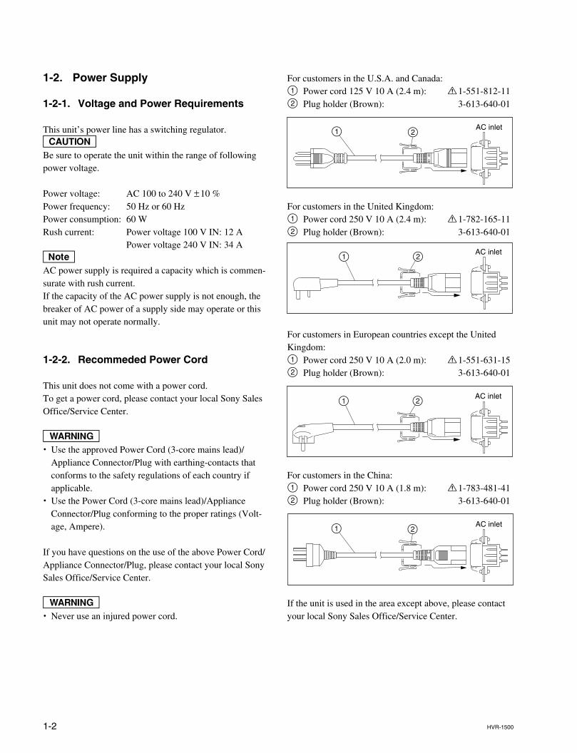
For customers in the U.S.A. and Canada:1 Power cord 125 V 10 A (2.4 m): ! 1-551-812-112 Plug holder (Brown): 3-613-640-01
For customers in the United Kingdom:1 Power cord 250 V 10 A (2.4 m): ! 1-782-165-112 Plug holder (Brown): 3-613-640-01
For customers in European countries except the UnitedKingdom:1 Power cord 250 V 10 A (2.0 m): ! 1-551-631-152 Plug holder (Brown): 3-613-640-01
For customers in the China:1 Power cord 250 V 10 A (1.8 m): ! 1-783-481-412 Plug holder (Brown): 3-613-640-01
If the unit is used in the area except above, please contactyour local Sony Sales Office/Service Center.
AC inlet21
21 AC inlet
21 AC inlet
AC inlet21
1-2. Power Supply
1-2-1. Voltage and Power Requirements
This unit’s power line has a switching regulator.cBe sure to operate the unit within the range of followingpower voltage.
Power voltage: AC 100 to 240 V ±10 %Power frequency: 50 Hz or 60 HzPower consumption: 60 WRush current: Power voltage 100 V IN: 12 A
Power voltage 240 V IN: 34 AnAC power supply is required a capacity which is commen-surate with rush current.If the capacity of the AC power supply is not enough, thebreaker of AC power of a supply side may operate or thisunit may not operate normally.
1-2-2. Recommeded Power Cord
This unit does not come with a power cord.To get a power cord, please contact your local Sony SalesOffice/Service Center.
w. Use the approved Power Cord (3-core mains lead)/
Appliance Connector/Plug with earthing-contacts thatconforms to the safety regulations of each country ifapplicable.
. Use the Power Cord (3-core mains lead)/ApplianceConnector/Plug conforming to the proper ratings (Volt-age, Ampere).
If you have questions on the use of the above Power Cord/Appliance Connector/Plug, please contact your local SonySales Office/Service Center.
w. Never use an injured power cord.
1-3HVR-1500
1-3. Supplied Accessories
. Operating instructions : 1
. Operating instructions (CD-ROM) : 1
1-4. Optional Accessories
. AC power cord
. Analog input board : HVBK-1505
. 9-pin remote conrtrol cable : RCC-5G (Length : 5 m (16 ft))
. Remote control unit : DSRM-10
. Digital video cassette : PDV-184*/124*/94*/64* (Standard-size (L) )PDVM-40*/32*/22*/12* (Mini-size (S) )PHDV-276DM*/186DM*/124DM*/64DM* (Standard-size (L) )PHDVM-63DM* (Mini-size (S) )nThe * in each model name is actually “ME” (indicating that a cassettememory is contained), “N” (indicating that no cassette memory iscontained) or “MEM” (indicating a master tape).
. Cleaning cassette tape : PDV12CL (Standard size), PDVM12CL (Mini size)
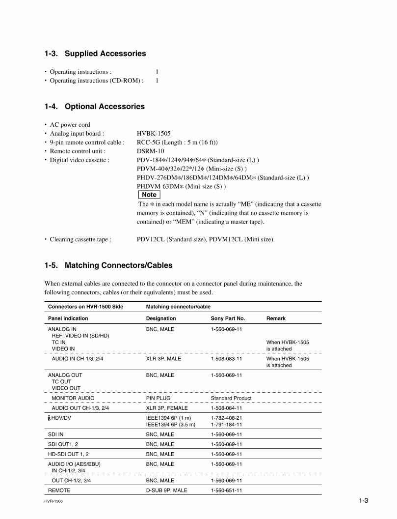
1-5. Matching Connectors/Cables
When external cables are connected to the connector on a connector panel during maintenance, thefollowing connectors, cables (or their equivalents) must be used.
Connectors on HVR-1500 Side Matching connector/cable
Panel indication Designation Sony Part No. Remark
ANALOG IN BNC, MALE 1-560-069-11REF. VIDEO IN (SD/HD)TC IN When HVBK-1505VIDEO IN is attached
AUDIO IN CH-1/3, 2/4 XLR 3P, MALE 1-508-083-11 When HVBK-1505is attached
ANALOG OUT BNC, MALE 1-560-069-11TC OUTVIDEO OUT
MONITOR AUDIO PIN PLUG Standard Product
AUDIO OUT CH-1/3, 2/4 XLR 3P, FEMALE 1-508-084-11
HDV/DV IEEE1394 6P (1 m) 1-782-408-21IEEE1394 6P (3.5 m) 1-791-184-11
SDI IN BNC, MALE 1-560-069-11
SDI OUT1, 2 BNC, MALE 1-560-069-11
HD-SDI OUT 1, 2 BNC, MALE 1-560-069-11
AUDIO I/O (AES/EBU) BNC, MALE 1-560-069-11IN CH-1/2, 3/4
OUT CH-1/2, 3/4 BNC, MALE 1-560-069-11
REMOTE D-SUB 9P, MALE 1-560-651-11
1-4 HVR-1500
1-6. Input/Output Signals of the Connectors
INPUTREF. VIDEO IN (SD/HD) : BNC x 2 (loop-through with 75 Z automatic terminator)
SD composite sync, black burst: 0.286 V p-p (525/60) or 0.3 V p-p (625/50), 75 Z, negative syncHD tri-level sync: 0.3 V, 75 Z, negative sync
VIDEO IN: BNC x 4 (When HVBK-1505 is attached)Composite
Y/S-Y/CPST and 1 loop-through connector with 75 Z automaticterminator: 1.0 V p-p, 75 Z, negative sync
ComponentY/S-Y/CPST: 1.0 V p-p, 75 Z, negative syncR-Y/S-C and B-Y: 0.7 V p-p (75 % color bars for 525/59.94 or 100%color bars for 625/50) , 75 Z
S-videoY/S-Y/CPST: 1.0 V p-p, 75 Z, negative syncR-Y/S-C: 0.286 V p-p (525/59.94) or 0.3 V p-p (625/50), 75 Z (burstlevel)
SDI IN: BNC x 1Serial digital interface format (270 Mbps), SMPTE 259M/ITU-R BT.656
AUDIO IN: XLR 3-pin x 2, FEMALE (When HVBK-1505 is attached)+4/0/_3*/_6 dBm , high impedance, balanced*: For 625/50 only
AUDIO I/O (AES/EBU) : BNC x 2Complying with AES-3id-1995
TC IN: BNC x 1, SMPTE timecode (525/59.94) or EBU timecode (625/50)0.5 V p-p to 18 V p-p, 3.3 kZ, unbalanced
HDV/DV: 6-pin IEEE 1394 connector x 1
OUTPUTVIDEO OUT: BNC x 3
CompositeY/CPST: 1.0 V p-p, 75 Z, negative sync
Component (SD)Y/CPST: 1.0 V p-p, 75 Z, negative syncPr/R-Y/S-C and Pb/B-Y/S-Y: 0.7 V p-p (75% color bars for 525/59.94or 100% color bars for 625/50),75 Z
Component (HD)Y: 1.0 V p-p, 75 Z, negative syncPr, Pb: 0.7 V p-p, 75 Z
S-videoPb/B-Y/S-Y: 1.0 V p-p, 75 Z, negative syncPr/R-Y/S-C: 0.286 V p-p (525/59.94) or 0.3 V p-p (625/50), 75 Z (burstlevel)
Monitor video outputBNC x 1(SUPER) CPST: 1.0 V p-p, 75 Z, negative sync
SDI OUT: BNC x 2Serial digital interface format (270 Mbps), SMPTE 259M/ITU-R BT.656
1-5HVR-1500
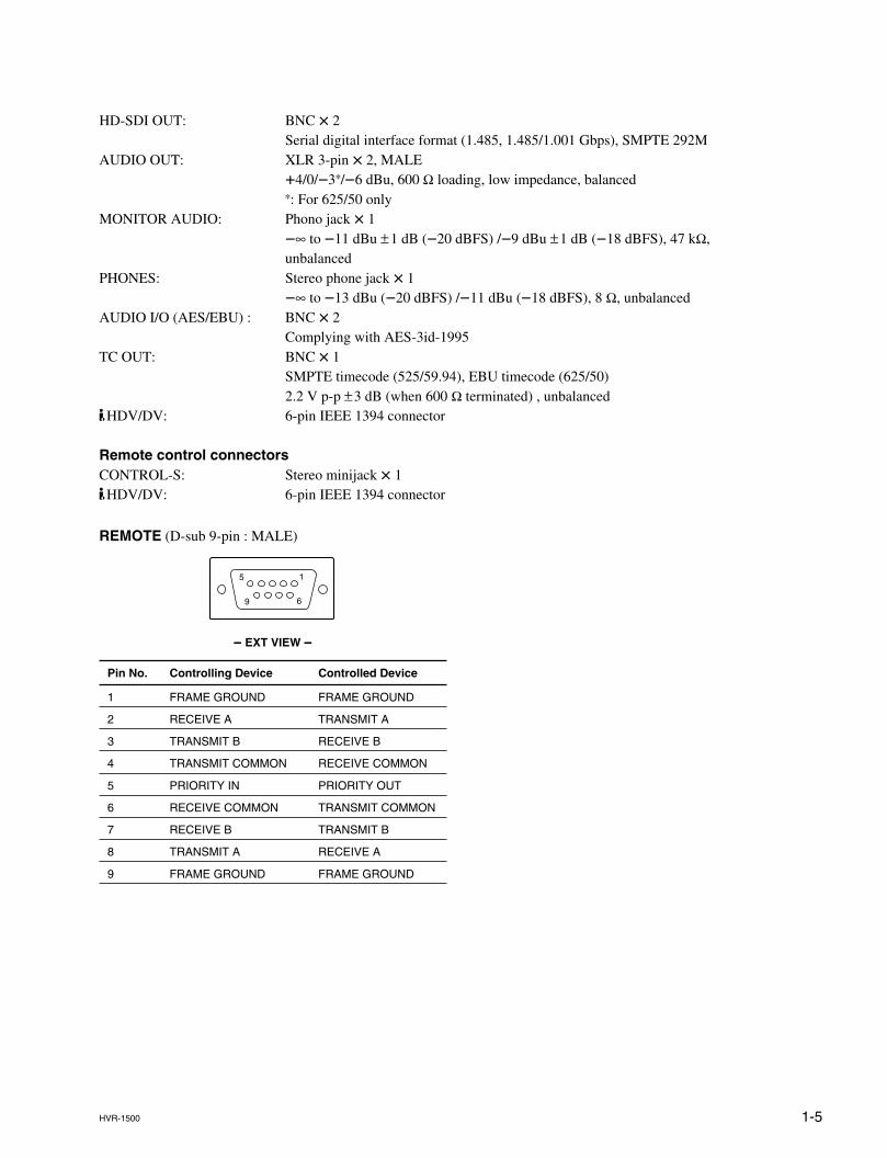
HD-SDI OUT: BNC x 2Serial digital interface format (1.485, 1.485/1.001 Gbps), SMPTE 292M
AUDIO OUT: XLR 3-pin x 2, MALE+4/0/_3*/_6 dBu, 600 Z loading, low impedance, balanced*: For 625/50 only
MONITOR AUDIO: Phono jack x 1_∞ to _11 dBu ±1 dB (_20 dBFS) /_9 dBu ±1 dB (_18 dBFS), 47 kZ,unbalanced
PHONES: Stereo phone jack x 1_∞ to _13 dBu (_20 dBFS) /_11 dBu (_18 dBFS), 8 Z, unbalanced
AUDIO I/O (AES/EBU) : BNC x 2Complying with AES-3id-1995
TC OUT: BNC x 1SMPTE timecode (525/59.94), EBU timecode (625/50)2.2 V p-p ±3 dB (when 600 Z terminated) , unbalanced
HDV/DV: 6-pin IEEE 1394 connector
Remote control connectorsCONTROL-S: Stereo minijack x 1
HDV/DV: 6-pin IEEE 1394 connector
REMOTE (D-sub 9-pin : MALE)
_____ EXT VIEW _____
Pin No. Controlling Device Controlled Device
1 FRAME GROUND FRAME GROUND
2 RECEIVE A TRANSMIT A
3 TRANSMIT B RECEIVE B
4 TRANSMIT COMMON RECEIVE COMMON
5 PRIORITY IN PRIORITY OUT
6 RECEIVE COMMON TRANSMIT COMMON
7 RECEIVE B TRANSMIT B
8 TRANSMIT A RECEIVE A
9 FRAME GROUND FRAME GROUND
5
9 6
1
1-6 HVR-1500
1-7. Installation Setup and Adjustment
1-7-1. Front Panel Setting
Front panel1. i.LINK INPUT SELECT button setting
i.LINK : HDV: Video and audio signals in HDVformat
i.LINK : DV *: Video and audio signals in DV
formati.LINK : DVCAM
*: Video and audio signals in
DVCAM format*: The display follows the recording format setting in
the REC FORMAT menu item. (Refer to theoperating instructions for details)
2. VIDEO INPUT SELECT button settingCOMPOSITE: Composite video signal
(When HVBK-1505 is attached)S VIDEO: S-video (separated Y and C)
signals (When HVBK-1505 isattached)
COMPONENT SD: Component video signals(When HVBK-1505 is attached)
SDI: SDI video signalSG: Video test signal
3. AUDIO INPUT SELECT button settingANALOG: Analog audio signal
(When HVBK-1505 is attached)AES/EBU: Digital audio signal in AES/
EBU formatSDI: Digital audio signal in SDI
formatSG: Audio test signal
4. AUDIO VARIABLE switch settingPRESET : Sets both the REC and PB levels
to the normal level.REC : Sets the REC audio level of the
channels respectively with theCH-1/2/3/4 knobs.
PB : Sets the PB audio level of thechannels respectively with theCH-1/2/3/4 knobs.
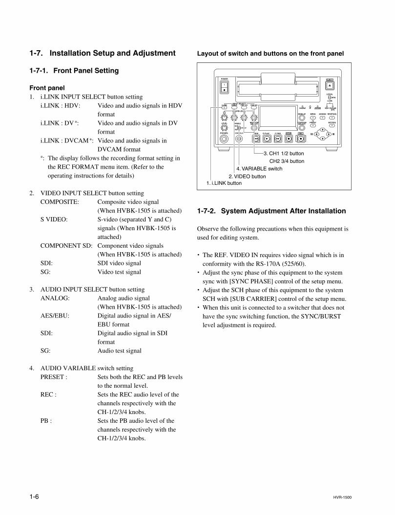
Layout of switch and buttons on the front panel
1-7-2. System Adjustment After Installation
Observe the following precautions when this equipment isused for editing system.
. The REF. VIDEO IN requires video signal which is inconformity with the RS-170A (525/60).
. Adjust the sync phase of this equipment to the systemsync with [SYNC PHASE] control of the setup menu.
. Adjust the SCH phase of this equipment to the systemSCH with [SUB CARRIER] control of the setup menu.
. When this unit is connected to a switcher that does nothave the sync switching function, the SYNC/BURSTlevel adjustment is required.
1. i.LINK button2. VIDEO button
3. CH1 1/2 button
CH2 3/4 button
4. VARIABLE switch
2-1HVR-1500
Section 2Service Overview
2-1. Location of Main Parts
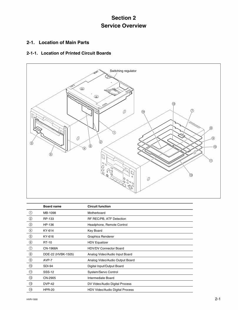
2-1-1. Location of Printed Circuit Boards
Board name Circuit function
1 MB-1098 Motherboard
2 RP-133 RF REC/PB, ATF Detection
3 HP-136 Headphone, Remote Control
4 KY-614 Key Board
5 KY-616 Graphics Renderer
6 RT-10 HDV Equalizer
7 CN-1968A HDV/DV Connector Board
8 DDE-22 (HVBK-1505) Analog Video/Audio Input Board
9 AVP-7 Analog Video/Audio Output Board
!/ SDI-94 Digital Input/Output Board
!- SSS-12 System/Servo Control
!= CN-2905 Intermediate Board
![ DVP-42 DV Video/Audio Digital Process
!] HPR-20 HDV Video/Audio Digital Process
!-
0
9
7
3
5
4
1
2
6
Switching regulator
!]
!=
2-2 HVR-1500
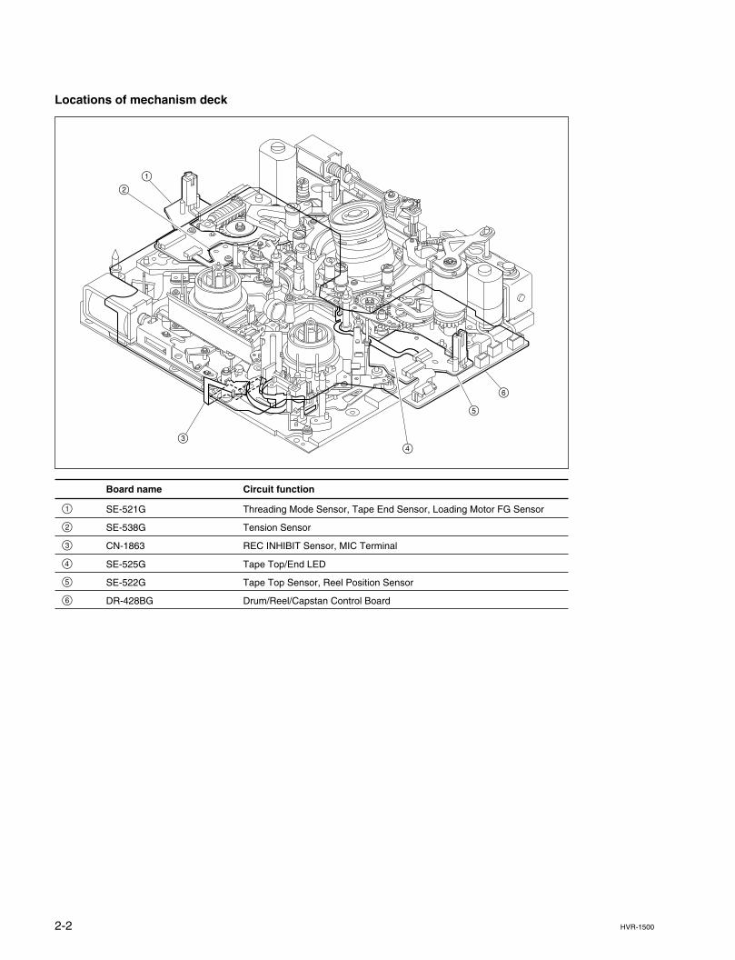
Locations of mechanism deck
Board name Circuit function
1 SE-521G Threading Mode Sensor, Tape End Sensor, Loading Motor FG Sensor
2 SE-538G Tension Sensor
3 CN-1863 REC INHIBIT Sensor, MIC Terminal
4 SE-525G Tape Top/End LED
5 SE-522G Tape Top Sensor, Reel Position Sensor
6 DR-428BG Drum/Reel/Capstan Control Board
6
5
43
12
2-3HVR-1500
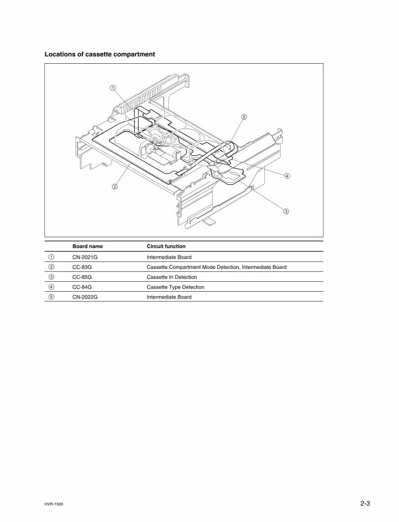
Locations of cassette compartment
Board name Circuit function
1 CN-2021G Intermediate Board
2 CC-83G Cassette Compartment Mode Detection, Intermediate Board
3 CC-85G Cassette In Detection
4 CC-84G Cassette Type Detection
5 CN-2022G Intermediate Board
2
1
3
4
5
2-4 HVR-1500
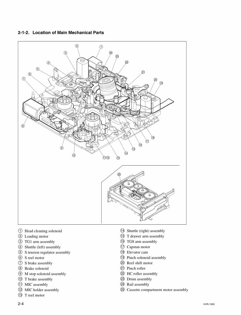
2-1-2. Location of Main Mechanical Parts
1 Head cleaning solenoid2 Loading motor3 TG1 arm assembly4 Shuttle (left) assembly5 S tension regulator assembly6 S reel motor7 S brake assembly8 Brake solenoid9 M stop solenoid assembly!/ T brake assembly!- MIC assembly!= MIC holder assembly![ T reel motor
!] Shuttle (right) assembly!\ T drawer arm assembly!; TG8 arm assembly!' Capstan motor!, Elevator cam!. Pinch solenoid assembly@/ Reel shift motor@- Pinch roller@= HC roller assembly@[ Drum assembly@] Rail assembly@\ Cassette compartment motor assembly
12
3
4
5
67
8
9
!= ![!]
!\!;
!,
!.@/
@-
@=
@[
0!-
@]
!'
@\
2-5HVR-1500
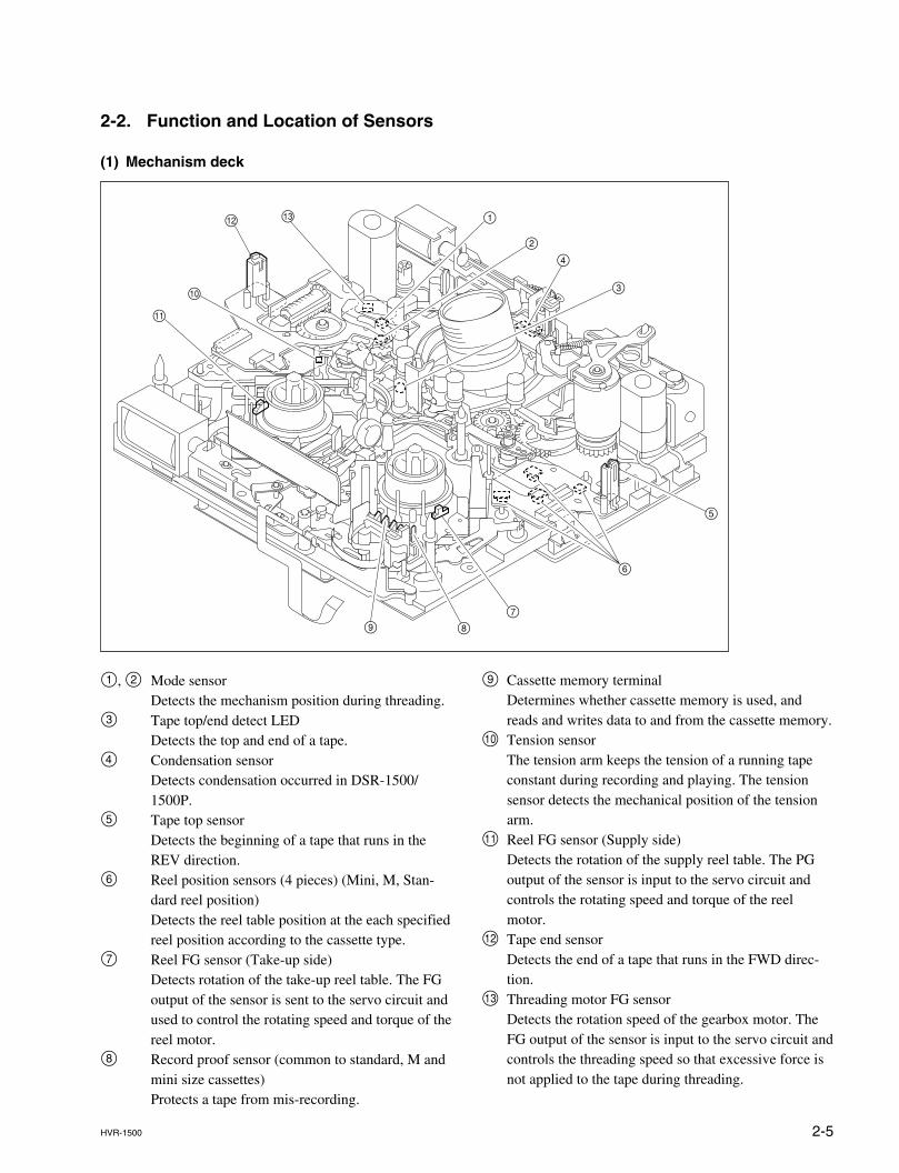
2-2. Function and Location of Sensors
(1) Mechanism deck
1, 2 Mode sensorDetects the mechanism position during threading.
3 Tape top/end detect LEDDetects the top and end of a tape.
4 Condensation sensorDetects condensation occurred in DSR-1500/1500P.
5 Tape top sensorDetects the beginning of a tape that runs in theREV direction.
6 Reel position sensors (4 pieces) (Mini, M, Stan-dard reel position)Detects the reel table position at the each specifiedreel position according to the cassette type.
7 Reel FG sensor (Take-up side)Detects rotation of the take-up reel table. The FGoutput of the sensor is sent to the servo circuit andused to control the rotating speed and torque of thereel motor.
8 Record proof sensor (common to standard, M andmini size cassettes)Protects a tape from mis-recording.
9 Cassette memory terminalDetermines whether cassette memory is used, andreads and writes data to and from the cassette memory.
!/ Tension sensorThe tension arm keeps the tension of a running tapeconstant during recording and playing. The tensionsensor detects the mechanical position of the tensionarm.
!- Reel FG sensor (Supply side)Detects the rotation of the supply reel table. The PGoutput of the sensor is input to the servo circuit andcontrols the rotating speed and torque of the reelmotor.
!= Tape end sensorDetects the end of a tape that runs in the FWD direc-tion.
2-6 HVR-1500
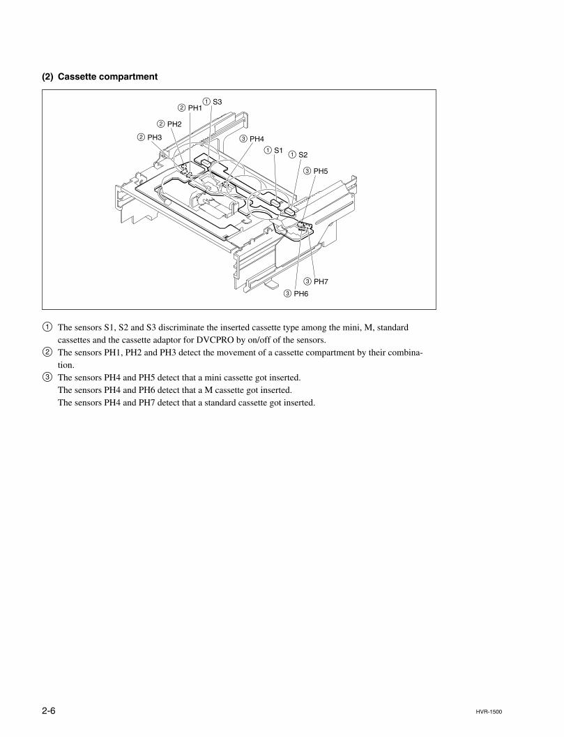
(2) Cassette compartment
1 The sensors S1, S2 and S3 discriminate the inserted cassette type among the mini, M, standardcassettes and the cassette adaptor for DVCPRO by on/off of the sensors.
2 The sensors PH1, PH2 and PH3 detect the movement of a cassette compartment by their combina-tion.
3 The sensors PH4 and PH5 detect that a mini cassette got inserted.The sensors PH4 and PH6 detect that a M cassette got inserted.The sensors PH4 and PH7 detect that a standard cassette got inserted.
2 PH3
2 PH1
3 PH4
1 S1
1 S3
1 S2
3 PH5
3 PH7
3 PH6
2 PH2
2-7HVR-1500
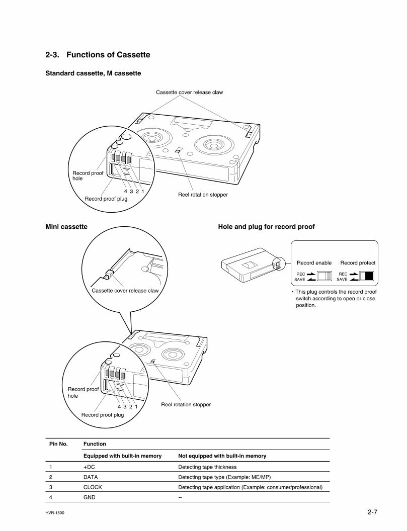
Record enable Record protect
RECSAVE
RECSAVE
. This plug controls the record proof switch according to open or close position.
4 3 2 1
Record proofhole
Record proof plug
Reel rotation stopper
Cassette cover release claw
2-3. Functions of Cassette
Standard cassette, M cassette
Mini cassette Hole and plug for record proof
Pin No. Function
Equipped with built-in memory Not equipped with built-in memory
1 +DC Detecting tape thickness
2 DATA Detecting tape type (Example: ME/MP)
3 CLOCK Detecting tape application (Example: consumer/professional)
4 GND _
Record proofhole
4 3 2 1Record proof plug
Cassette cover release claw
Reel rotation stopper
2-8 HVR-1500
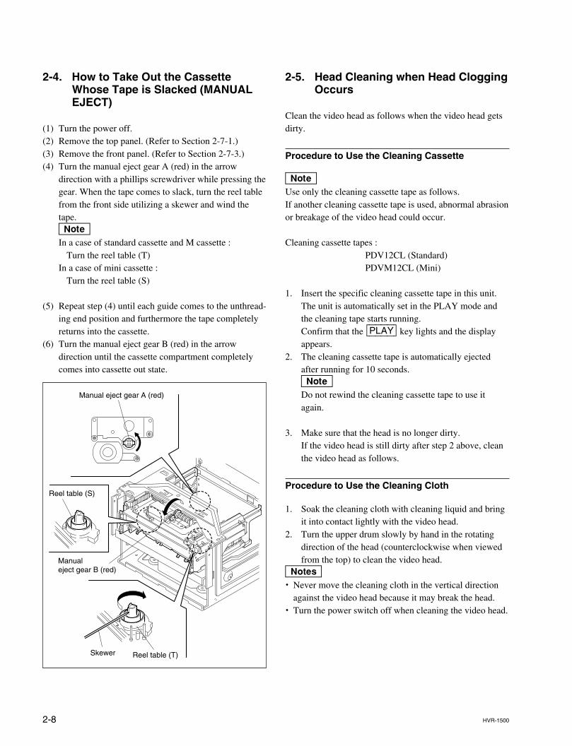
2-4. How to Take Out the CassetteWhose Tape is Slacked (MANUALEJECT)
(1) Turn the power off.(2) Remove the top panel. (Refer to Section 2-7-1.)(3) Remove the front panel. (Refer to Section 2-7-3.)(4) Turn the manual eject gear A (red) in the arrow
direction with a phillips screwdriver while pressing thegear. When the tape comes to slack, turn the reel tablefrom the front side utilizing a skewer and wind thetape.nIn a case of standard cassette and M cassette :
Turn the reel table (T)In a case of mini cassette :
Turn the reel table (S)
(5) Repeat step (4) until each guide comes to the unthread-ing end position and furthermore the tape completelyreturns into the cassette.
(6) Turn the manual eject gear B (red) in the arrowdirection until the cassette compartment completelycomes into cassette out state.
Manual eject gear A (red)
Skewer Reel table (T)
Manual eject gear B (red)
Reel table (S)
2-5. Head Cleaning when Head CloggingOccurs
Clean the video head as follows when the video head getsdirty.
Procedure to Use the Cleaning Cassette
nUse only the cleaning cassette tape as follows.If another cleaning cassette tape is used, abnormal abrasionor breakage of the video head could occur.
Cleaning cassette tapes :PDV12CL (Standard)PDVM12CL (Mini)
1. Insert the specific cleaning cassette tape in this unit.The unit is automatically set in the PLAY mode andthe cleaning tape starts running.Confirm that the [PLAY] key lights and the displayappears.
2. The cleaning cassette tape is automatically ejectedafter running for 10 seconds.nDo not rewind the cleaning cassette tape to use itagain.
3. Make sure that the head is no longer dirty.If the video head is still dirty after step 2 above, cleanthe video head as follows.
Procedure to Use the Cleaning Cloth
1. Soak the cleaning cloth with cleaning liquid and bringit into contact lightly with the video head.
2. Turn the upper drum slowly by hand in the rotatingdirection of the head (counterclockwise when viewedfrom the top) to clean the video head.
m. Never move the cleaning cloth in the vertical direction
against the video head because it may break the head.. Turn the power switch off when cleaning the video head.
2-9HVR-1500
2-6. Operating the VTR without aCassette Tape
The VTR can be operated without a cassette tape by thefollowing switch setting.
Switch Setting
1. Remove the cassette compartment from this unit.2. Turn on switches S401-4 of the SSS-12 board.3. Then turn on the main power.
Operating Method
ThreadingWhile pressing the S/T reel motors, press the [STOP] key.The upper drum rotates, threading ring rotates. The unitenters the threading mode.The tension arm and the threading ring move to thespecified position, then the threading is completed.This condition in which the threading is completed isreferred to as the STOP status.
PLAYPress the [PLAY] key.The pinch roller is pressed against the capstan shaft toenter the PLAY status.When the [PLAY] key is pressed during threading, thepinch roller is pressed against the capstan shaft to enter thePLAY status after the threading has completed.
FFPress the [F|FWD] key.The pinch roller is pressed against the capstan shaft to setthe FWD.SEARCH to five-times speed.
REWPress the [REW] key.The pinch roller is pressed against the capstan shaft to setREV.SEARCH to five-times speed.
RECWhile pressing the record proof sensor on the right side ofthe T side reel table, press both the [PLAY] key and the[REC] key.The pinch roller is pressed against the capstan shaft toenter REC status.When the record proof sensor is released, the REC status isreleased and the recorder returns to PLAY status.
UnthreadingPress the [EJECT] key.Each guide moves to the specified position to complete theunthreading.
Reel position selectionPress the SET (YES) key on the control panel.Reel position will be changed as shown below in accor-dance with the number of pressing the SET (YES) key.
nMake sure to turn off switches S401-4 on the SSS-12board after the adjustment.
Mini M STD
2-10 HVR-1500
2-7. Removing/Installing the Cabinets
nBefore removing the cabinets, be sure to turn off the mainpower.
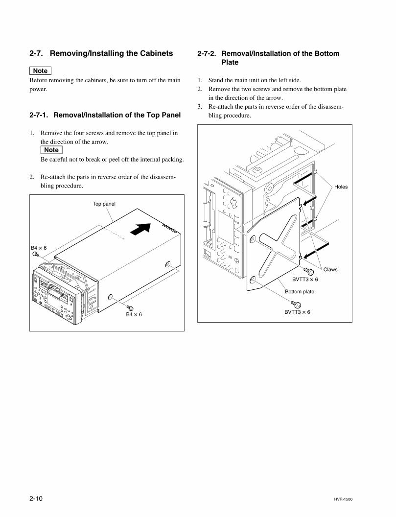
2-7-1. Removal/Installation of the Top Panel
1. Remove the four screws and remove the top panel inthe direction of the arrow.nBe careful not to break or peel off the internal packing.
2. Re-attach the parts in reverse order of the disassem-bling procedure.
2-7-2. Removal/Installation of the BottomPlate
1. Stand the main unit on the left side.2. Remove the two screws and remove the bottom plate
in the direction of the arrow.3. Re-attach the parts in reverse order of the disassem-
bling procedure.
Top panel
B4 x 6
B4 x 6
Bottom plate
Holes
Claws
BVTT3 x 6
BVTT3 x 6
2-11HVR-1500
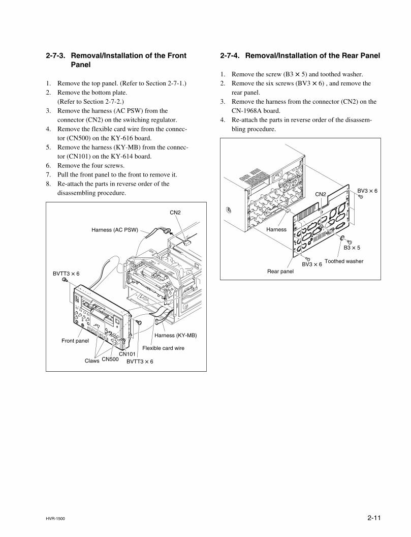
2-7-3. Removal/Installation of the FrontPanel
1. Remove the top panel. (Refer to Section 2-7-1.)2. Remove the bottom plate.
(Refer to Section 2-7-2.)3. Remove the harness (AC PSW) from the
connector (CN2) on the switching regulator.4. Remove the flexible card wire from the connec-
tor (CN500) on the KY-616 board.5. Remove the harness (KY-MB) from the connec-
tor (CN101) on the KY-614 board.6. Remove the four screws.7. Pull the front panel to the front to remove it.8. Re-attach the parts in reverse order of the
disassembling procedure.
CN2
Claws
Front panel
Harness (AC PSW)
Harness (KY-MB)
Flexible card wire
BVTT3 x 6
BVTT3 x 6CN101
CN500
2-7-4. Removal/Installation of the Rear Panel
1. Remove the screw (B3 x 5) and toothed washer.2. Remove the six screws (BV3 x 6) , and remove the
rear panel.3. Remove the harness from the connector (CN2) on the
CN-1968A board.4. Re-attach the parts in reverse order of the disassem-
bling procedure.
Harness
Rear panel
Toothed washer
BV3 x 6
B3 x 5
BV3 x 6
CN2
2-12 HVR-1500
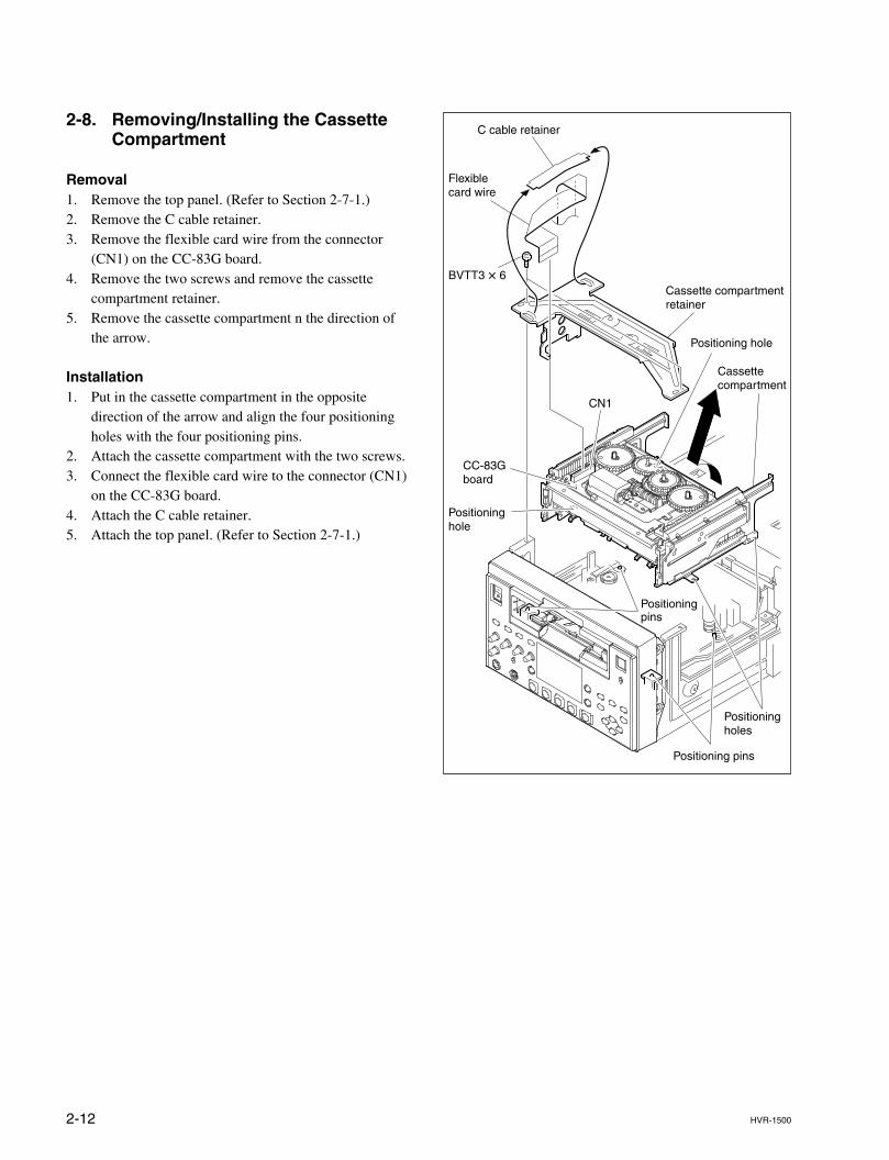
2-8. Removing/Installing the CassetteCompartment
Removal1. Remove the top panel. (Refer to Section 2-7-1.)2. Remove the C cable retainer.3. Remove the flexible card wire from the connector
(CN1) on the CC-83G board.4. Remove the two screws and remove the cassette
compartment retainer.5. Remove the cassette compartment n the direction of
the arrow.
Installation1. Put in the cassette compartment in the opposite
direction of the arrow and align the four positioningholes with the four positioning pins.
2. Attach the cassette compartment with the two screws.3. Connect the flexible card wire to the connector (CN1)
on the CC-83G board.4. Attach the C cable retainer.5. Attach the top panel. (Refer to Section 2-7-1.)
Cassette compartmentretainer
C cable retainer
Cassettecompartment
Positioning pins
Positioningholes
Positioninghole
Positioning hole
Positioningpins
Flexiblecard wire
CC-83Gboard
CN1
BVTT3 x 6
2-13HVR-1500
D203D202D201D200
1 2 3 4 5 6 7A
B
E
F
C
D
G
H
8
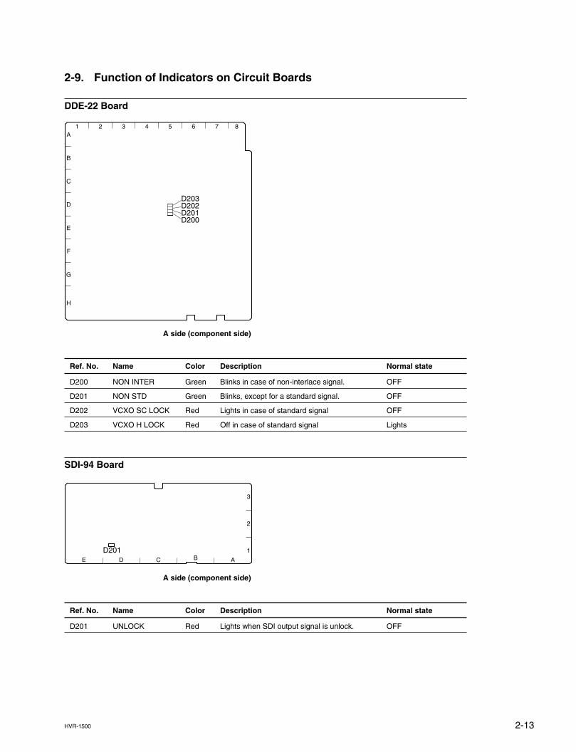
2-9. Function of Indicators on Circuit Boards
DDE-22 Board
A side (component side)
Ref. No. Name Color Description Normal state
D200 NON INTER Green Blinks in case of non-interlace signal. OFF
D201 NON STD Green Blinks, except for a standard signal. OFF
D202 VCXO SC LOCK Red Lights in case of standard signal OFF
D203 VCXO H LOCK Red Off in case of standard signal Lights
SDI-94 Board
A side (component side)
Ref. No. Name Color Description Normal state
D201 UNLOCK Red Lights when SDI output signal is unlock. OFF
D201AE D C B
1
3
2
2-14 HVR-1500
S401
6 5 4 32 1
A
B
D
C
S500S401
ABCDE
1
2
3
4
5
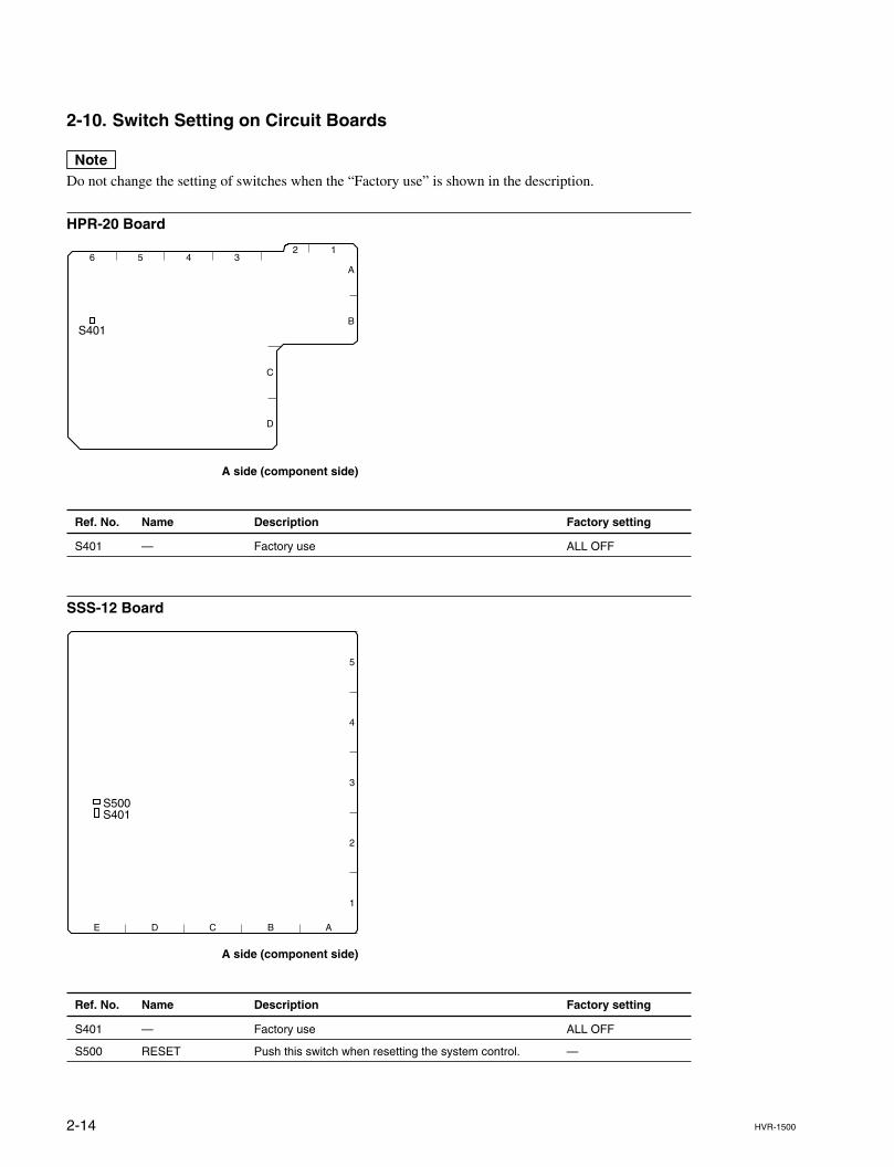
2-10. Switch Setting on Circuit Boards
nDo not change the setting of switches when the “Factory use” is shown in the description.
HPR-20 Board
A side (component side)
Ref. No. Name Description Factory setting
S401 — Factory use ALL OFF
SSS-12 Board
A side (component side)
Ref. No. Name Description Factory setting
S401 — Factory use ALL OFF
S500 RESET Push this switch when resetting the system control. —
2-15HVR-1500
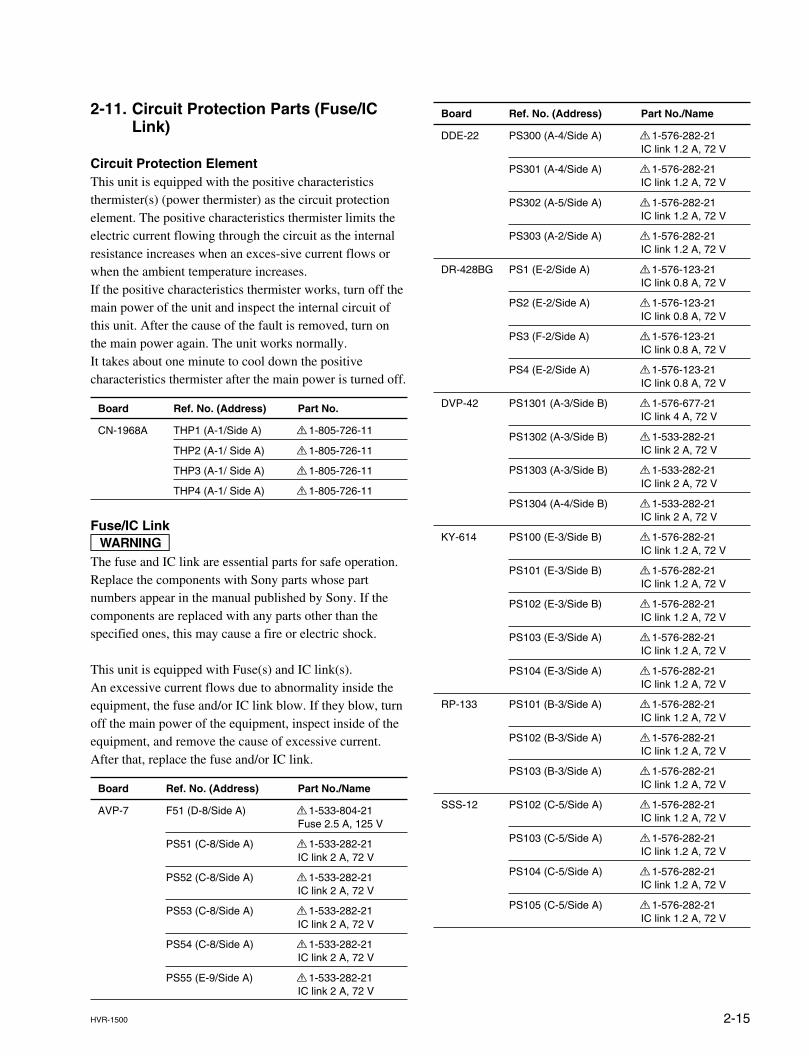
Board Ref. No. (Address) Part No./Name
DDE-22 PS300 (A-4/Side A) ! 1-576-282-21IC link 1.2 A, 72 V
PS301 (A-4/Side A) ! 1-576-282-21IC link 1.2 A, 72 V
PS302 (A-5/Side A) ! 1-576-282-21IC link 1.2 A, 72 V
PS303 (A-2/Side A) ! 1-576-282-21IC link 1.2 A, 72 V
DR-428BG PS1 (E-2/Side A) ! 1-576-123-21IC link 0.8 A, 72 V
PS2 (E-2/Side A) ! 1-576-123-21IC link 0.8 A, 72 V
PS3 (F-2/Side A) ! 1-576-123-21IC link 0.8 A, 72 V
PS4 (E-2/Side A) ! 1-576-123-21IC link 0.8 A, 72 V
DVP-42 PS1301 (A-3/Side B) ! 1-576-677-21IC link 4 A, 72 V
PS1302 (A-3/Side B) ! 1-533-282-21IC link 2 A, 72 V
PS1303 (A-3/Side B) ! 1-533-282-21IC link 2 A, 72 V
PS1304 (A-4/Side B) ! 1-533-282-21IC link 2 A, 72 V
KY-614 PS100 (E-3/Side B) ! 1-576-282-21IC link 1.2 A, 72 V
PS101 (E-3/Side B) ! 1-576-282-21IC link 1.2 A, 72 V
PS102 (E-3/Side B) ! 1-576-282-21IC link 1.2 A, 72 V
PS103 (E-3/Side A) ! 1-576-282-21IC link 1.2 A, 72 V
PS104 (E-3/Side A) ! 1-576-282-21IC link 1.2 A, 72 V
RP-133 PS101 (B-3/Side A) ! 1-576-282-21IC link 1.2 A, 72 V
PS102 (B-3/Side A) ! 1-576-282-21IC link 1.2 A, 72 V
PS103 (B-3/Side A) ! 1-576-282-21IC link 1.2 A, 72 V
SSS-12 PS102 (C-5/Side A) ! 1-576-282-21IC link 1.2 A, 72 V
PS103 (C-5/Side A) ! 1-576-282-21IC link 1.2 A, 72 V
PS104 (C-5/Side A) ! 1-576-282-21IC link 1.2 A, 72 V
PS105 (C-5/Side A) ! 1-576-282-21IC link 1.2 A, 72 V
2-11. Circuit Protection Parts (Fuse/ICLink)
Circuit Protection ElementThis unit is equipped with the positive characteristicsthermister(s) (power thermister) as the circuit protectionelement. The positive characteristics thermister limits theelectric current flowing through the circuit as the internalresistance increases when an exces-sive current flows orwhen the ambient temperature increases.If the positive characteristics thermister works, turn off themain power of the unit and inspect the internal circuit ofthis unit. After the cause of the fault is removed, turn onthe main power again. The unit works normally.It takes about one minute to cool down the positivecharacteristics thermister after the main power is turned off.
Board Ref. No. (Address) Part No.
CN-1968A THP1 (A-1/Side A) ! 1-805-726-11
THP2 (A-1/ Side A) ! 1-805-726-11
THP3 (A-1/ Side A) ! 1-805-726-11
THP4 (A-1/ Side A) ! 1-805-726-11
Fuse/IC LinkwThe fuse and IC link are essential parts for safe operation.Replace the components with Sony parts whose partnumbers appear in the manual published by Sony. If thecomponents are replaced with any parts other than thespecified ones, this may cause a fire or electric shock.
This unit is equipped with Fuse(s) and IC link(s).An excessive current flows due to abnormality inside theequipment, the fuse and/or IC link blow. If they blow, turnoff the main power of the equipment, inspect inside of theequipment, and remove the cause of excessive current.After that, replace the fuse and/or IC link.
Board Ref. No. (Address) Part No./Name
AVP-7 F51 (D-8/Side A) ! 1-533-804-21Fuse 2.5 A, 125 V
PS51 (C-8/Side A) ! 1-533-282-21IC link 2 A, 72 V
PS52 (C-8/Side A) ! 1-533-282-21IC link 2 A, 72 V
PS53 (C-8/Side A) ! 1-533-282-21IC link 2 A, 72 V
PS54 (C-8/Side A) ! 1-533-282-21IC link 2 A, 72 V
PS55 (E-9/Side A) ! 1-533-282-21IC link 2 A, 72 V
2-16 HVR-1500
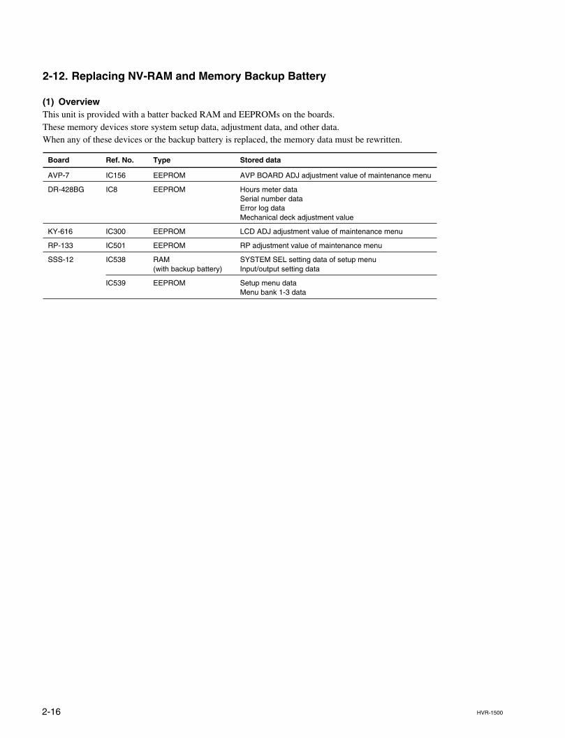
2-12. Replacing NV-RAM and Memory Backup Battery
(1) OverviewThis unit is provided with a batter backed RAM and EEPROMs on the boards.These memory devices store system setup data, adjustment data, and other data.When any of these devices or the backup battery is replaced, the memory data must be rewritten.
Board Ref. No. Type Stored data
AVP-7 IC156 EEPROM AVP BOARD ADJ adjustment value of maintenance menu
DR-428BG IC8 EEPROM Hours meter dataSerial number dataError log dataMechanical deck adjustment value
KY-616 IC300 EEPROM LCD ADJ adjustment value of maintenance menu
RP-133 IC501 EEPROM RP adjustment value of maintenance menu
SSS-12 IC538 RAM SYSTEM SEL setting data of setup menu(with backup battery) Input/output setting data
IC539 EEPROM Setup menu dataMenu bank 1-3 data
2-17HVR-1500
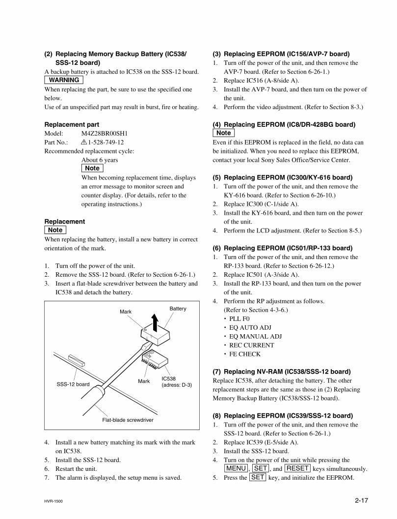
(2) Replacing Memory Backup Battery (IC538/SSS-12 board)
A backup battery is attached to IC538 on the SSS-12 board.wWhen replacing the part, be sure to use the specified onebelow.Use of an unspecified part may result in burst, fire or heating.
Replacement partModel: M4Z28BR00SH1Part No.: ! 1-528-749-12Recommended replacement cycle:
About 6 yearsnWhen becoming replacement time, displaysan error message to monitor screen andcounter display. (For details, refer to theoperating instructions.)
ReplacementnWhen replacing the battery, install a new battery in correctorientation of the mark.
1. Turn off the power of the unit.2. Remove the SSS-12 board. (Refer to Section 6-26-1.)3. Insert a flat-blade screwdriver between the battery and
IC538 and detach the battery.
4. Install a new battery matching its mark with the markon IC538.
5. Install the SSS-12 board.6. Restart the unit.7. The alarm is displayed, the setup menu is saved.
Battery
Mark
Mark
Flat-blade screwdriver
IC538(adress: D-3)SSS-12 board
(3) Replacing EEPROM (IC156/AVP-7 board)1. Turn off the power of the unit, and then remove the
AVP-7 board. (Refer to Section 6-26-1.)2. Replace IC516 (A-8/side A).3. Install the AVP-7 board, and then turn on the power of
the unit.4. Perform the video adjustment. (Refer to Section 8-3.)
(4) Replacing EEPROM (IC8/DR-428BG board)nEven if this EEPROM is replaced in the field, no data canbe initialized. When you need to replace this EEPROM,contact your local Sony Sales Office/Service Center.
(5) Replacing EEPROM (IC300/KY-616 board)1. Turn off the power of the unit, and then remove the
KY-616 board. (Refer to Section 6-26-10.)2. Replace IC300 (C-1/side A).3. Install the KY-616 board, and then turn on the power
of the unit.4. Perform the LCD adjustment. (Refer to Section 8-5.)
(6) Replacing EEPROM (IC501/RP-133 board)1. Turn off the power of the unit, and then remove the
RP-133 board. (Refer to Section 6-26-12.)2. Replace IC501 (A-3/side A).3. Install the RP-133 board, and then turn on the power
of the unit.4. Perform the RP adjustment as follows.
(Refer to Section 4-3-6.). PLL F0. EQ AUTO ADJ. EQ MANUAL ADJ. REC CURRENT. FE CHECK
(7) Replacing NV-RAM (IC538/SSS-12 board)Replace IC538, after detaching the battery. The otherreplacement steps are the same as those in (2) ReplacingMemory Backup Battery (IC538/SSS-12 board).
(8) Replacing EEPROM (IC539/SSS-12 board)1. Turn off the power of the unit, and then remove the
SSS-12 board. (Refer to Section 6-26-1.)2. Replace IC539 (E-5/side A).3. Install the SSS-12 board.4. Turn on the power of the unit while pressing the
[MENU], [SET], and [RESET] keys simultaneously.5. Press the [SET] key, and initialize the EEPROM.
2-18 HVR-1500
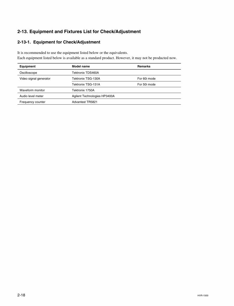
2-13. Equipment and Fixtures List for Check/Adjustment
2-13-1. Equipment for Check/Adjustment
It is recommended to use the equipment listed below or the equivalents.Each equipment listed below is available as a standard product. However, it may not be producted now.
Equipment Model name Remarks
Oscilloscope Tektronix TDS460A
Video signal generator Tektronix TSG-130A For 60i mode
Tektronix TSG-131A For 50i mode
Waveform monitor Tektronix 1750A
Audio level meter Agilent Technologies HP3400A
Frequency counter Advantest TR5821
2-19HVR-1500
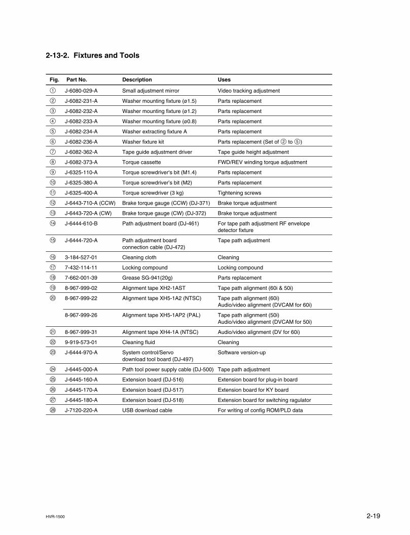
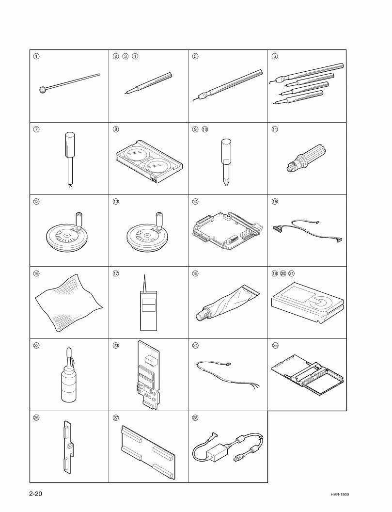
2-13-2. Fixtures and Tools
Fig. Part No. Description Uses
1 J-6080-029-A Small adjustment mirror Video tracking adjustment
2 J-6082-231-A Washer mounting fixture (ø1.5) Parts replacement
3 J-6082-232-A Washer mounting fixture (ø1.2) Parts replacement
4 J-6082-233-A Washer mounting fixture (ø0.8) Parts replacement
5 J-6082-234-A Washer extracting fixture A Parts replacement
6 J-6082-236-A Washer fixture kit Parts replacement (Set of 2 to 5)
7 J-6082-362-A Tape guide adjustment driver Tape guide height adjustment
8 J-6082-373-A Torque cassette FWD/REV winding torque adjustment
9 J-6325-110-A Torque screwdriver‘s bit (M1.4) Parts replacement
!/ J-6325-380-A Torque screwdriver’s bit (M2) Parts replacement
!- J-6325-400-A Torque screwdriver (3 kg) Tightening screws
!= J-6443-710-A (CCW) Brake torque gauge (CCW) (DJ-371) Brake torque adjustment
![ J-6443-720-A (CW) Brake torque gauge (CW) (DJ-372) Brake torque adjustment
!] J-6444-610-B Path adjustment board (DJ-461) For tape path adjustment RF envelopedetector fixture
!\ J-6444-720-A Path adjustment board Tape path adjustmentconnection cable (DJ-472)
!; 3-184-527-01 Cleaning cloth Cleaning
!' 7-432-114-11 Locking compound Locking compound
!, 7-662-001-39 Grease SG-941(20g) Parts replacement
!. 8-967-999-02 Alignment tape XH2-1AST Tape path alignment (60i & 50i)
@/ 8-967-999-22 Alignment tape XH5-1A2 (NTSC) Tape path alignment (60i)Audio/video alignment (DVCAM for 60i)
8-967-999-26 Alignment tape XH5-1AP2 (PAL) Tape path alignment (50i)Audio/video alignment (DVCAM for 50i)
@- 8-967-999-31 Alignment tape XH4-1A (NTSC) Audio/video alignment (DV for 60i)
@= 9-919-573-01 Cleaning fluid Cleaning
@[ J-6444-970-A System control/Servo Software version-updownload tool board (DJ-497)
@] J-6445-000-A Path tool power supply cable (DJ-500) Tape path adjustment
@\ J-6445-160-A Extension board (DJ-516) Extension board for plug-in board
@; J-6445-170-A Extension board (DJ-517) Extension board for KY board
@' J-6445-180-A Extension board (DJ-518) Extension board for switching ragulator
@, J-7120-220-A USB download cable For writing of config ROM/PLD data
2-20 HVR-1500
1 2 3 4 5 6
7 8 9 !/ !-
!= ![ !] !\
!; !'
@= @[
@;
@] @\
!, !. @/ @-
DJ-371DJ-372
@' @,
2-21HVR-1500
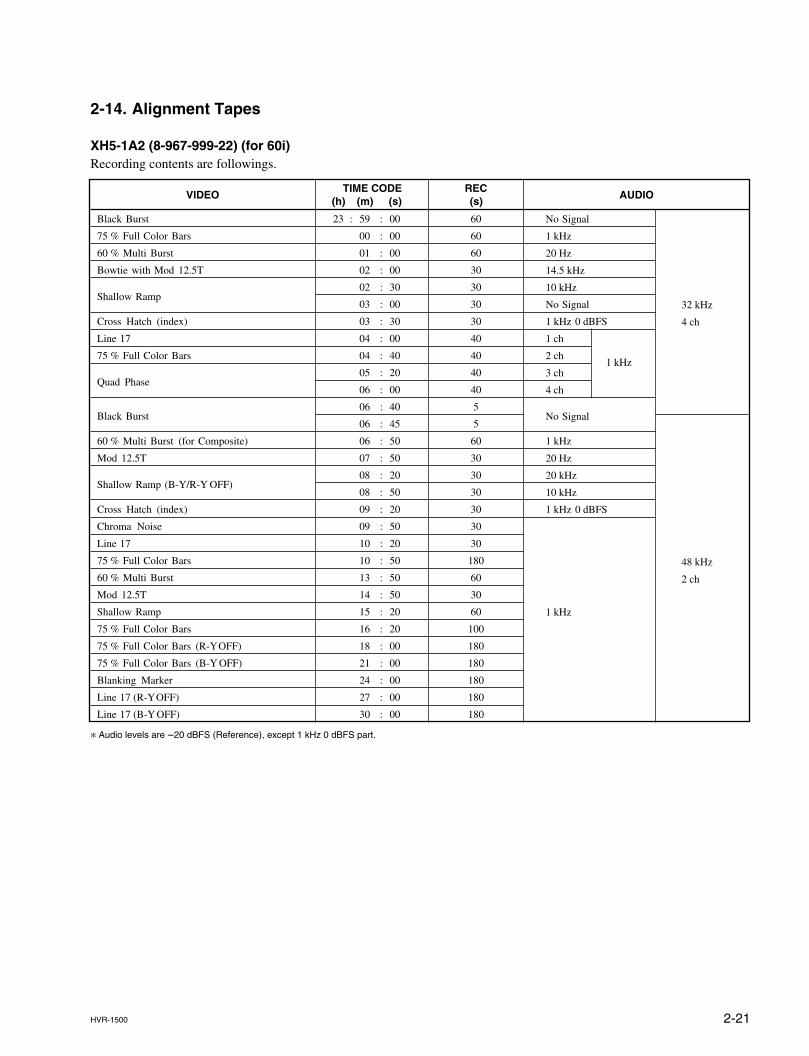
2-14. Alignment Tapes
XH5-1A2 (8-967-999-22) (for 60i)Recording contents are followings.
* Audio levels are _20 dBFS (Reference), except 1 kHz 0 dBFS part.
VIDEO
Black Burst
75 % Full Color Bars
60 % Multi Burst
Bowtie with Mod 12.5T
Shallow Ramp
Cross Hatch (index)
Line 17
75 % Full Color Bars
Quad Phase
Black Burst
60 % Multi Burst (for Composite)
Mod 12.5T
Shallow Ramp (B-Y/R-Y OFF)
Cross Hatch (index)
Chroma Noise
Line 17
75 % Full Color Bars
60 % Multi Burst
Mod 12.5T
Shallow Ramp
75 % Full Color Bars
75 % Full Color Bars (R-Y OFF)
75 % Full Color Bars (B-Y OFF)
Blanking Marker
Line 17 (R-Y OFF)
Line 17 (B-Y OFF)
TIME CODE(h) (m) (s)
23 : 59 : 00
00 : 00
01 : 00
02 : 00
02 : 30
03 : 00
03 : 30
04 : 00
04 : 40
05 : 20
06 : 00
06 : 40
06 : 45
06 : 50
07 : 50
08 : 20
08 : 50
09 : 20
09 : 50
10 : 20
10 : 50
13 : 50
14 : 50
15 : 20
16 : 20
18 : 00
21 : 00
24 : 00
27 : 00
30 : 00
REC(s)
60
60
60
30
30
30
30
40
40
40
40
5
5
60
30
30
30
30
30
30
180
60
30
60
100
180
180
180
180
180
No Signal
1 kHz
20 Hz
14.5 kHz
10 kHz
No Signal
1 kHz 0 dBFS
1 ch
2 ch1 kHz
3 ch
4 ch
No Signal
1 kHz
20 Hz
20 kHz
10 kHz
1 kHz 0 dBFS
1 kHz
32 kHz
4 ch
48 kHz
2 ch
AUDIO
2-22 HVR-1500
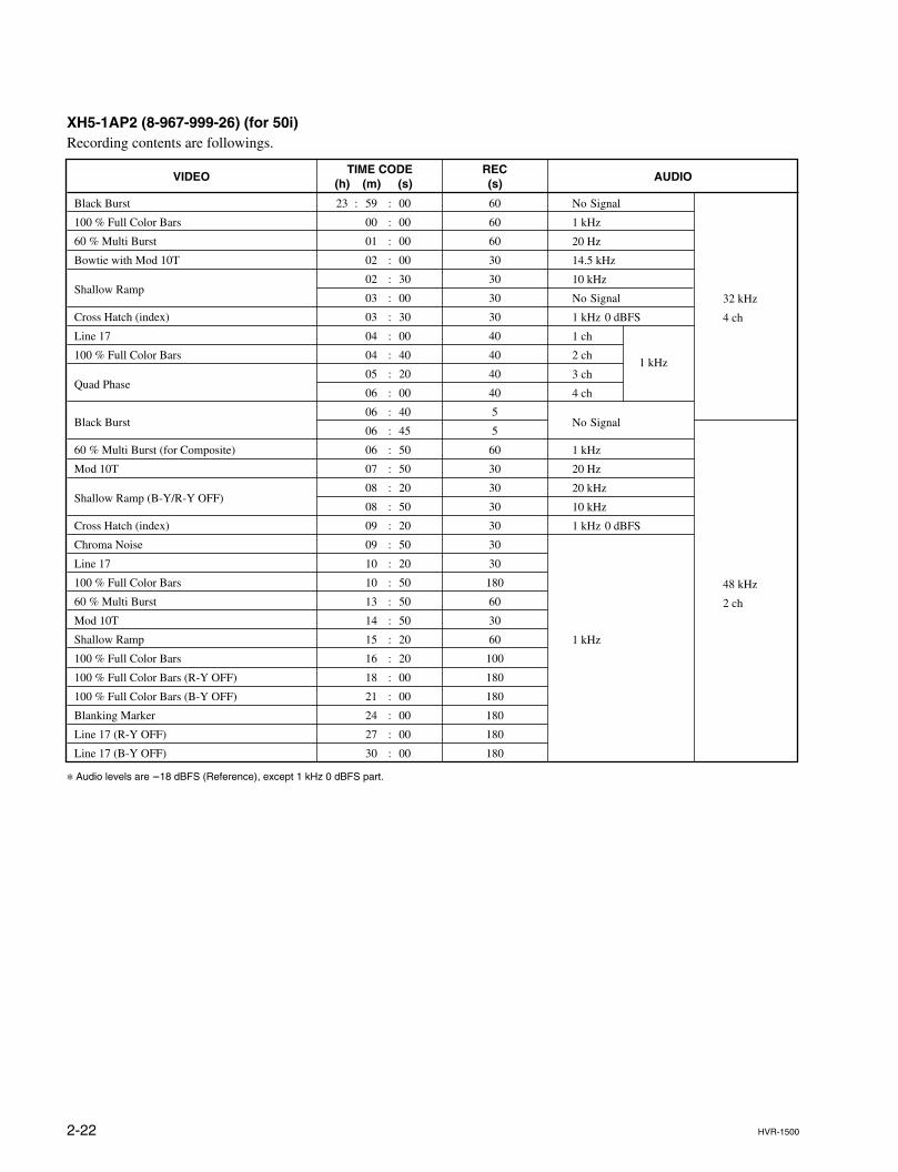
XH5-1AP2 (8-967-999-26) (for 50i)Recording contents are followings.
* Audio levels are _18 dBFS (Reference), except 1 kHz 0 dBFS part.
VIDEO
Black Burst
100 % Full Color Bars
60 % Multi Burst
Bowtie with Mod 10T
Shallow Ramp
Cross Hatch (index)
Line 17
100 % Full Color Bars
Quad Phase
Black Burst
60 % Multi Burst (for Composite)
Mod 10T
Shallow Ramp (B-Y/R-Y OFF)
Cross Hatch (index)
Chroma Noise
Line 17
100 % Full Color Bars
60 % Multi Burst
Mod 10T
Shallow Ramp
100 % Full Color Bars
100 % Full Color Bars (R-Y OFF)
100 % Full Color Bars (B-Y OFF)
Blanking Marker
Line 17 (R-Y OFF)
Line 17 (B-Y OFF)
TIME CODE(h) (m) (s)
23 : 59 : 00
00 : 00
01 : 00
02 : 00
02 : 30
03 : 00
03 : 30
04 : 00
04 : 40
05 : 20
06 : 00
06 : 40
06 : 45
06 : 50
07 : 50
08 : 20
08 : 50
09 : 20
09 : 50
10 : 20
10 : 50
13 : 50
14 : 50
15 : 20
16 : 20
18 : 00
21 : 00
24 : 00
27 : 00
30 : 00
REC(s)
60
60
60
30
30
30
30
40
40
40
40
5
5
60
30
30
30
30
30
30
180
60
30
60
100
180
180
180
180
180
No Signal
1 kHz
20 Hz
14.5 kHz
10 kHz
No Signal
1 kHz 0 dBFS
1 ch
2 ch1 kHz
3 ch
4 ch
No Signal
1 kHz
20 Hz
20 kHz
10 kHz
1 kHz 0 dBFS
1 kHz
32 kHz
4 ch
48 kHz
2 ch
AUDIO
2-23HVR-1500
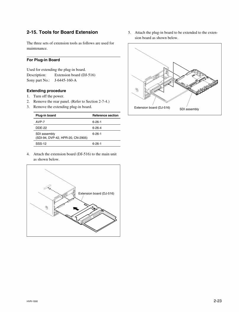
5. Attach the plug-in board to be extended to the exten-sion board as shown below.
2-15. Tools for Board Extension
The three sets of extension tools as follows are used formaintenance.
For Plug-in Board
Used for extending the plug-in board.Description: Extension board (DJ-516)Sony part No.: J-6445-160-A
Extending procedure1. Turn off the power.2. Remove the rear panel. (Refer to Section 2-7-4.)3. Remove the extending plug-in board.
Plug-in board Reference section
AVP-7 6-26-1
DDE-22 6-26-4
SDI assembly 6-26-1(SDI-94, DVP-42, HPR-20, CN-2905)
SSS-12 6-26-1
4. Attach the extension board (DJ-516) to the main unitas shown below.
Extension board (DJ-516)
Extension board (DJ-516) SDI assembly
2-24 HVR-1500
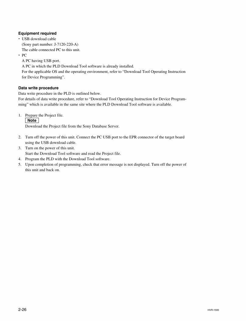
Extension board(DJ-518)
Switching regulator
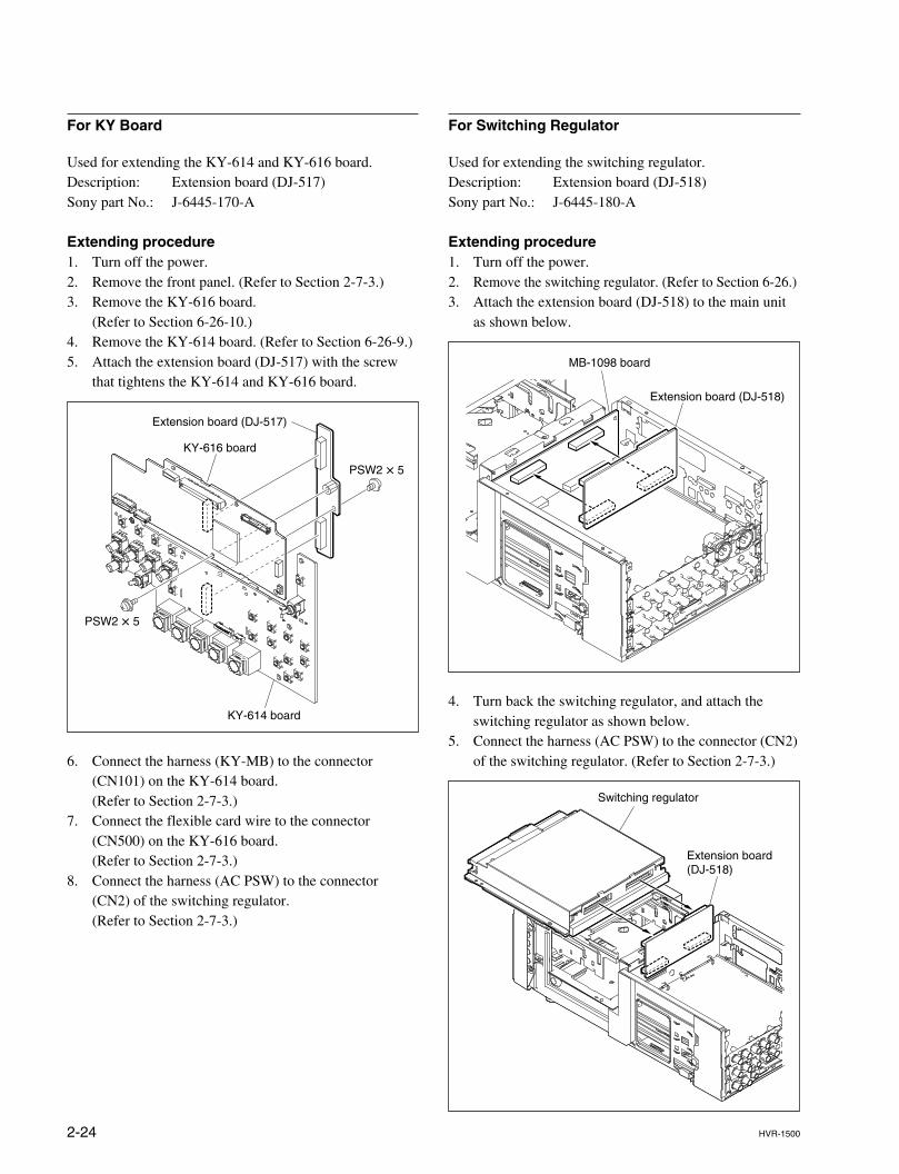
For KY Board
Used for extending the KY-614 and KY-616 board.Description: Extension board (DJ-517)Sony part No.: J-6445-170-A
Extending procedure1. Turn off the power.2. Remove the front panel. (Refer to Section 2-7-3.)3. Remove the KY-616 board.
(Refer to Section 6-26-10.)4. Remove the KY-614 board. (Refer to Section 6-26-9.)5. Attach the extension board (DJ-517) with the screw
that tightens the KY-614 and KY-616 board.
6. Connect the harness (KY-MB) to the connector(CN101) on the KY-614 board.(Refer to Section 2-7-3.)
7. Connect the flexible card wire to the connector(CN500) on the KY-616 board.(Refer to Section 2-7-3.)
8. Connect the harness (AC PSW) to the connector(CN2) of the switching regulator.(Refer to Section 2-7-3.)
For Switching Regulator
Used for extending the switching regulator.Description: Extension board (DJ-518)Sony part No.: J-6445-180-A
Extending procedure1. Turn off the power.2. Remove the switching regulator. (Refer to Section 6-26.)3. Attach the extension board (DJ-518) to the main unit
as shown below.
4. Turn back the switching regulator, and attach theswitching regulator as shown below.
5. Connect the harness (AC PSW) to the connector (CN2)of the switching regulator. (Refer to Section 2-7-3.)
PSW2 x 5
PSW2 x 5
Extension board (DJ-517)
KY-616 board
KY-614 board
Extension board (DJ-518)
MB-1098 board
2-25HVR-1500
2-16. Writing and Rewriting the PLD Internal Data
This unit uses the PLD (Programmable Logic Device).Writing and rewriting the PLD internal data shown below supported by the e-Production (EPR) system.If the PLD needs to be upgraded, contact your Sony Sales Office/Service Center.
e-Production system has the advantages shown below.. To write/rewrite the PLD internal data:
1. The standard fixture (cable) can be used.2. The standard software (PLD Download Tool) can be used.
. The PLD internal data is controlled in the Sony Database Server under the name Project file(E_xxx_xxx_xx_xx).
. The printed circuit board is equipped with the standard connector (EPR connector) to write the PLDinternal data. The indication “EPR” is shown on the printed circuit board.
PLD supported by the e-Production
Board EPR connector Ref. No. PLD Ref. No. Project File No.
AVP-7 CN2 IC154 E_000_003_71_xx
DDE-21 CN200 IC202 E_000_003_66_xx
DVP-42 CN901 IC805, IC10012 E_000_003_69_xx
IC805 E_000_003_67_xx
IC1001 E_000_003_68_xx
HPR-20 CN1201 IC1203 E_000_003_70_xx
KY-616 CN501 IC507 E_000_003_74_xx
RT-10 CN201 IC200 E_000_003_75_xx
SDI-94 CN701 IC705 E_000_003_72_xx
CN601 IC601 E_000_003_73_xx
SSS-12 CN401 IC401 E_000_003_65_xx
2-26 HVR-1500
Equipment required. USB download cable
(Sony part number: J-7120-220-A)The cable connected PC to this unit.
. PCA PC having USB port.A PC in which the PLD Download Tool software is already installed.For the applicable OS and the operating environment, refer to “Download Tool Operating Instructionfor Device Programming”.
Data write procedureData write procedure in the PLD is outlined below.For details of data write procedure, refer to “Download Tool Operating Instruction for Device Program-ming” which is available in the same site where the PLD Download Tool software is available.
1. Prepare the Project file.nDownload the Project file from the Sony Database Server.
2. Turn off the power of this unit. Connect the PC USB port to the EPR connector of the target boardusing the USB download cable.
3. Turn on the power of this unit.Start the Download Tool software and read the Project file.
4. Program the PLD with the Download Tool software.5. Upon completion of programming, check that error message is not displayed. Turn off the power of
this unit and back on.
2-27HVR-1500
2-17. Firmware Update
The HVR-1500 mounts the CPU for SY and SV on the SSS-12 board and uses flash ROMs for loadingthis program.Do the following procedure to upgrade the version of the flash ROMs mounted on the board.There are two methods of the upgrading the flash ROMs.(1) High-speed writing using the fixture board, J-6444-970-A (DJ-497)(2) Writing by downloading from a PC (through RS-422)
2-17-1. Upgrading the Version Using the Fixture Board
1. Setting the fixture board DJ-497Write the CPU software to be written into the following PROMs.
ROMs to be used on the fixture DJ-497:SV CPU M27C4001-10F1-(G) (8-759-568-73) or equivalentSY CPU M27C4001-10F1-(G) (8-759-568-73) or equivalent
As these CPUs employ 16 bits data bus, 2 pieces of PROMs are required for one CPU.Write softwares into PROMs in the 8 bit split mode. A PROM at even address side is for CN102.A PROM at odd address side is for CN101.
(1) Insert the PROMs, in which CPU software are written, into the socket on the fixture board DJ-497.(2) Set bit 1 of S1 on the fixture DJ-497 to OPEN (upper side) and the rest of bits to the board side
(lower side).(3) Set S3 on the fixture DJ-497 to [ROM] side and S2 on the fixture DJ-497 to [DOWN] side.(4) Set S4 on the fixture DJ-497 to [8M].
2-28 HVR-1500
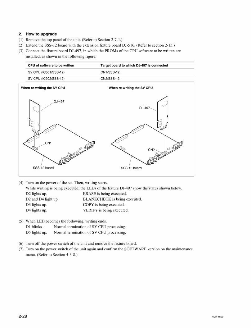
2. How to upgrade(1) Remove the top panel of the unit. (Refer to Section 2-7-1.)(2) Extend the SSS-12 board with the extension fixture board DJ-516. (Refer to section 2-15.)(3) Connect the fixture board DJ-497, in which the PROMs of the CPU software to be written are
installed, as shown in the following figure.
CPU of software to be written Target board to which DJ-497 is connected
SY CPU (IC501/SSS-12) CN1/SSS-12
SV CPU (IC202/SSS-12) CN2/SSS-12
(4) Turn on the power of the set. Then, writing starts.While writing is being executed, the LEDs of the fixture DJ-497 show the status shown below.D2 lights up. ERASE is being executed.D2 and D4 light up. BLANKCHECK is being executed.D3 lights up. COPY is being executed.D4 lights up. VERIFY is being executed.
(5) When LED becomes the following, writing ends.D1 blinks. Normal termination of SY CPU processing.D5 lights up. Normal termination of SV CPU processing.
(6) Turn off the power switch of the unit and remove the fixture board.(7) Turn on the power switch of the unit again and confirm the SOFTWARE version on the maintenance
menu. (Refer to Section 4-3-8.)
When re-writing the SY CPU When re-writing the SV CPU
DJ-497
SSS-12 board
CN1
DJ-497
SSS-12 board
CN2
2-29HVR-1500
REMOTE
HVR-1500PC
PORT1
RS-232Cport
RS-232C/RS-422conversion box
HPR-20CN402
HVR-1500PC
PORT2
RS-232Cport RS-232C-6PIN
cable
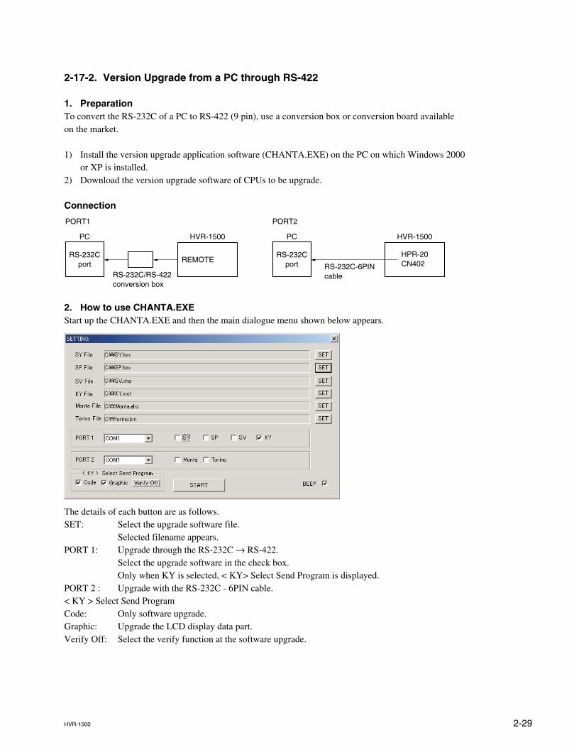
2-17-2. Version Upgrade from a PC through RS-422
1. PreparationTo convert the RS-232C of a PC to RS-422 (9 pin), use a conversion box or conversion board availableon the market.
1) Install the version upgrade application software (CHANTA.EXE) on the PC on which Windows 2000or XP is installed.
2) Download the version upgrade software of CPUs to be upgrade.
Connection
2. How to use CHANTA.EXEStart up the CHANTA.EXE and then the main dialogue menu shown below appears.
The details of each button are as follows.SET: Select the upgrade software file.
Selected filename appears.PORT 1: Upgrade through the RS-232C → RS-422.
Select the upgrade software in the check box.Only when KY is selected, < KY> Select Send Program is displayed.
PORT 2 : Upgrade with the RS-232C - 6PIN cable.< KY > Select Send ProgramCode: Only software upgrade.Graphic: Upgrade the LCD display data part.Verify Off: Select the verify function at the software upgrade.
2-30 HVR-1500
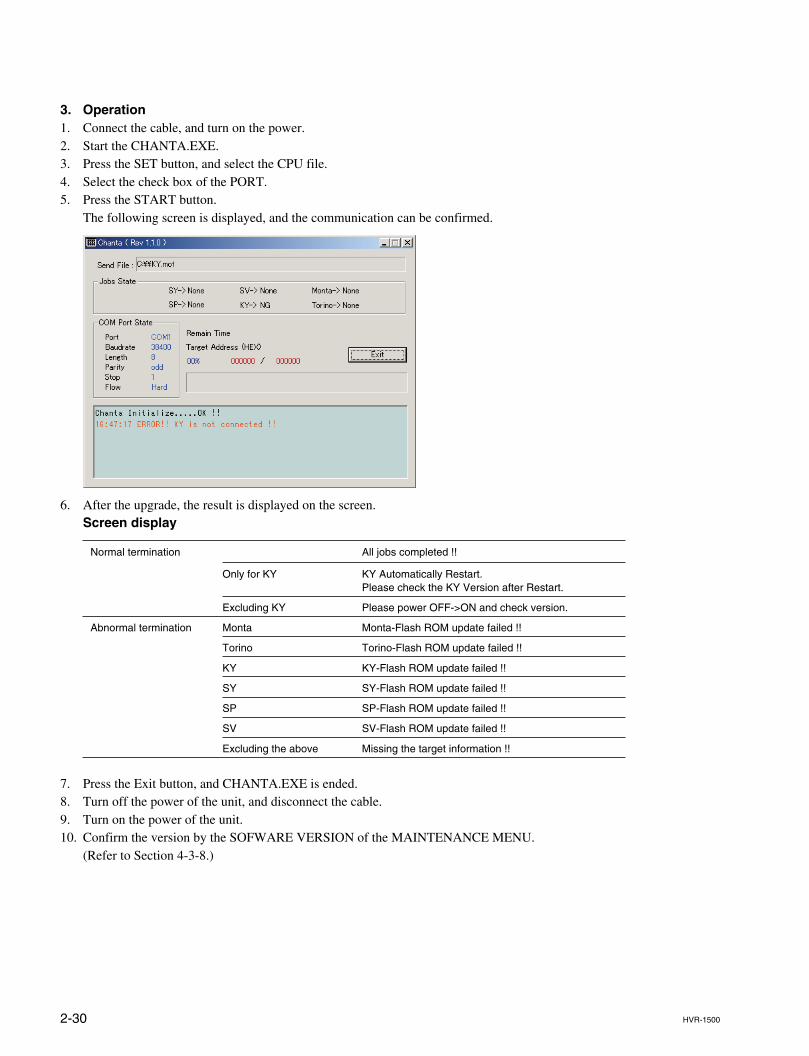
3. Operation1. Connect the cable, and turn on the power.2. Start the CHANTA.EXE.3. Press the SET button, and select the CPU file.4. Select the check box of the PORT.5. Press the START button.
The following screen is displayed, and the communication can be confirmed.
6. After the upgrade, the result is displayed on the screen.Screen display
Normal termination All jobs completed !!
Only for KY KY Automatically Restart.Please check the KY Version after Restart.
Excluding KY Please power OFF->ON and check version.
Abnormal termination Monta Monta-Flash ROM update failed !!
Torino Torino-Flash ROM update failed !!
KY KY-Flash ROM update failed !!
SY SY-Flash ROM update failed !!
SP SP-Flash ROM update failed !!
SV SV-Flash ROM update failed !!
Excluding the above Missing the target information !!
7. Press the Exit button, and CHANTA.EXE is ended.8. Turn off the power of the unit, and disconnect the cable.9. Turn on the power of the unit.10. Confirm the version by the SOFWARE VERSION of the MAINTENANCE MENU.
(Refer to Section 4-3-8.)
2-31HVR-1500
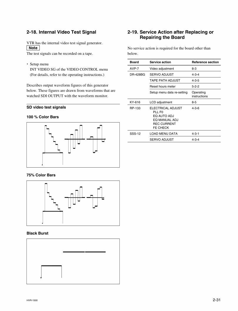
2-18. Internal Video Test Signal
VTR has the internal video test signal generator.nThe test signals can be recorded on a tape.
. Setup menuINT VIDEO SG of the VIDEO CONTROL menu(For details, refer to the operating instructions.)
Describes output waveform figures of this generatorbelow. These figures are drawn from waveforms that arewatched SDI OUTPUT with the waveform monitor.
SD video test signals
100 % Color Bars
75% Color Bars
Black Burst
2-19. Service Action after Replacing orRepairing the Board
No service action is required for the board other thanbelow.
Board Service action Reference section
AVP-7 Video adjustment 8-3
DR-428BG SERVO ADJUST 4-3-4
TAPE PATH ADJUST 4-3-5
Reset hours meter 5-2-2
Setup menu data re-setting Operatinginstructions
KY-616 LCD adjustment 8-5
RP-133 ELECTRICAL ADJUST 4-3-6PLL F0EQ AUTO ADJEQ MANUAL ADJREC CURRENTFE CHECK
SSS-12 LOAD MENU DATA 4-3-1
SERVO ADJUST 4-3-4
2-32 HVR-1500
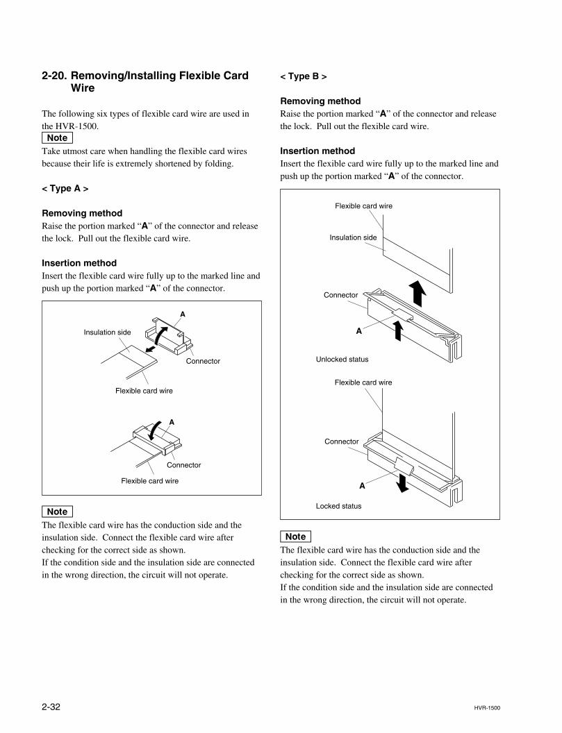
< Type B >
Removing methodRaise the portion marked “A” of the connector and releasethe lock. Pull out the flexible card wire.
Insertion methodInsert the flexible card wire fully up to the marked line andpush up the portion marked “A” of the connector.
nThe flexible card wire has the conduction side and theinsulation side. Connect the flexible card wire afterchecking for the correct side as shown.If the condition side and the insulation side are connectedin the wrong direction, the circuit will not operate.
2-20. Removing/Installing Flexible CardWire
The following six types of flexible card wire are used inthe HVR-1500.nTake utmost care when handling the flexible card wiresbecause their life is extremely shortened by folding.
< Type A >
Removing methodRaise the portion marked “A” of the connector and releasethe lock. Pull out the flexible card wire.
Insertion methodInsert the flexible card wire fully up to the marked line andpush up the portion marked “A” of the connector.
nThe flexible card wire has the conduction side and theinsulation side. Connect the flexible card wire afterchecking for the correct side as shown.If the condition side and the insulation side are connectedin the wrong direction, the circuit will not operate.
Flexible card wire
Connector
Connector
Flexible card wire
A
A
Insulation side
Flexible card wire
Insulation side
Connector
A
Unlocked status
Locked status
Flexible card wire
A
Connector
2-33HVR-1500
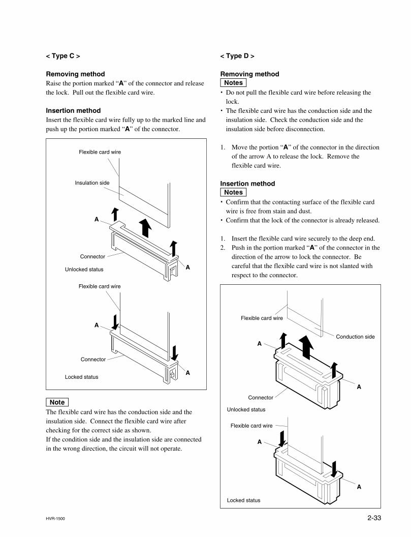
< Type D >
Removing methodm. Do not pull the flexible card wire before releasing the
lock.. The flexible card wire has the conduction side and the
insulation side. Check the conduction side and theinsulation side before disconnection.
1. Move the portion “A” of the connector in the directionof the arrow A to release the lock. Remove theflexible card wire.
Insertion methodm. Confirm that the contacting surface of the flexible card
wire is free from stain and dust.. Confirm that the lock of the connector is already released.
1. Insert the flexible card wire securely to the deep end.2. Push in the portion marked “A” of the connector in the
direction of the arrow to lock the connector. Becareful that the flexible card wire is not slanted withrespect to the connector.
< Type C >
Removing methodRaise the portion marked “A” of the connector and releasethe lock. Pull out the flexible card wire.
Insertion methodInsert the flexible card wire fully up to the marked line andpush up the portion marked “A” of the connector.
nThe flexible card wire has the conduction side and theinsulation side. Connect the flexible card wire afterchecking for the correct side as shown.If the condition side and the insulation side are connectedin the wrong direction, the circuit will not operate.
A
A
A
A
Flexible card wire
Insulation side
Connector
Unlocked status
Locked status
Flexible card wire
Connector
A
A
A
A
Flexible card wire
Connector
Conduction side
Unlocked status
Locked status
Flexible card wire
2-34 HVR-1500
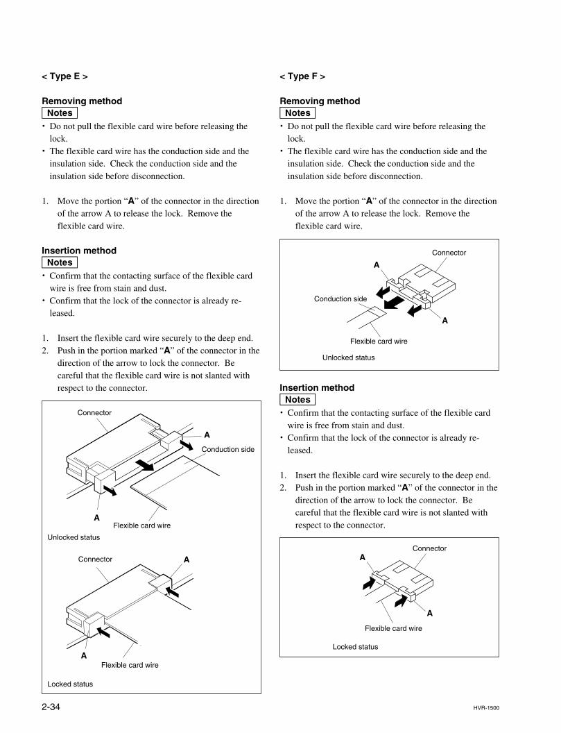
< Type F >
Removing methodm. Do not pull the flexible card wire before releasing the
lock.. The flexible card wire has the conduction side and the
insulation side. Check the conduction side and theinsulation side before disconnection.
1. Move the portion “A” of the connector in the directionof the arrow A to release the lock. Remove theflexible card wire.
Insertion methodm. Confirm that the contacting surface of the flexible card
wire is free from stain and dust.. Confirm that the lock of the connector is already re-
leased.
1. Insert the flexible card wire securely to the deep end.2. Push in the portion marked “A” of the connector in the
direction of the arrow to lock the connector. Becareful that the flexible card wire is not slanted withrespect to the connector.
< Type E >
Removing methodm. Do not pull the flexible card wire before releasing the
lock.. The flexible card wire has the conduction side and the
insulation side. Check the conduction side and theinsulation side before disconnection.
1. Move the portion “A” of the connector in the directionof the arrow A to release the lock. Remove theflexible card wire.
Insertion methodm. Confirm that the contacting surface of the flexible card
wire is free from stain and dust.. Confirm that the lock of the connector is already re-
leased.
1. Insert the flexible card wire securely to the deep end.2. Push in the portion marked “A” of the connector in the
direction of the arrow to lock the connector. Becareful that the flexible card wire is not slanted withrespect to the connector.
A
A
A
A
Flexible card wire
Connector
Unlocked status
Locked status
Flexible card wire
Connector
Conduction side
A
A
Flexible card wire
Connector
Unlocked status
Conduction side
A
A
Locked status
Flexible card wire
Connector
2-35HVR-1500
2-21. Unleaded Solder
Unleaded solder is used for all the boards of this unit.Boards requiring use of unleaded solder are printed with alead free mark (LF) indicating the solder contains no lead.(Caution: Some printed circuit boards may not comeprinted with the lead free mark due to their particular size.)
: LEAD FREE MARK
m. Be sure to use the unleaded solder for the boards of this
unit.. The unleaded solder melts at a temperature about 40 dC
higher than the ordinary solder, therefore, it is recom-mended to use the soldering iron having a temperatureregulator.
. The ordinary soldering iron can be used but the iron tiphas to be applied to the solder joint for a slightly longertime. The printed pattern (copper foil) may peel away ifthe heated tip is applied for too long, so be careful.
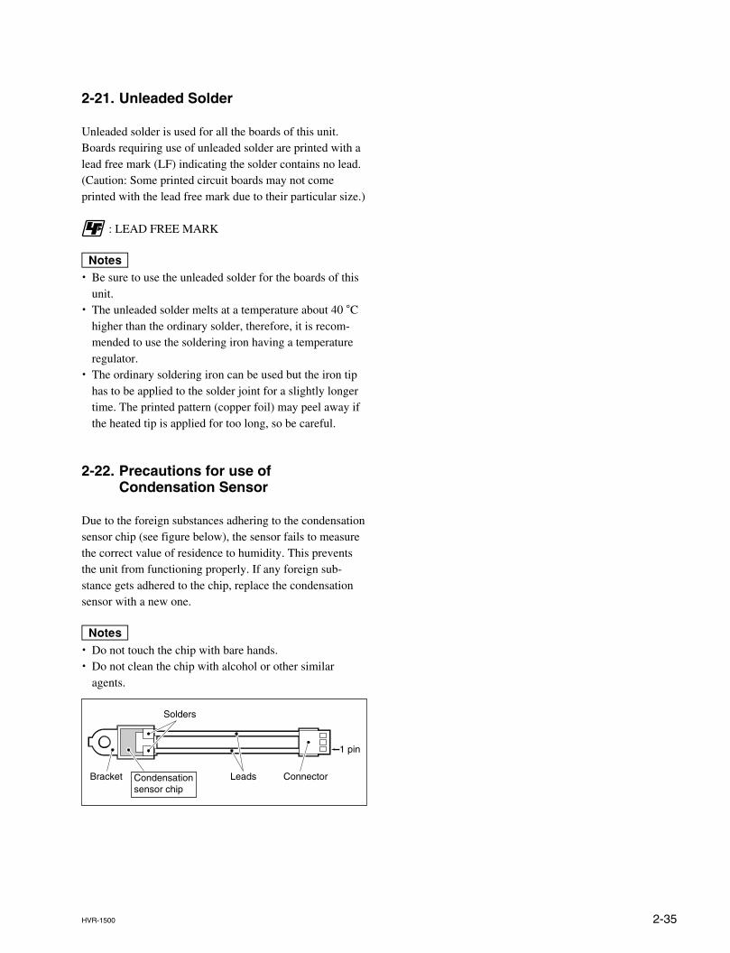
2-22. Precautions for use ofCondensation Sensor
Due to the foreign substances adhering to the condensationsensor chip (see figure below), the sensor fails to measurethe correct value of residence to humidity. This preventsthe unit from functioning properly. If any foreign sub-stance gets adhered to the chip, replace the condensationsensor with a new one.
m. Do not touch the chip with bare hands.. Do not clean the chip with alcohol or other similar
agents.
Connector
1 pin
LeadsCondensationsensor chip
Bracket
Solders

3-1HVR-1500
Section 3Error Messages
3-1. Alarm Display
This unit has an alarm display function.When a problem is detected, an alarm is displayed immediately in the time counter display. The alarmand a message describing the countermeasure are displayed on the monitor area in the LCD and a videomonitor connected to the CPST (SUPER) connector.This unit has two types of alarms : one is for operators while the other is for service persons. Thismanual describes only the alarms for service persons. For details of alarms for operators, refer to theoperating instruction. Activating the alarm display may influence the system, such as when the referencevideo signal is not used. Therefore, you can select whether or not to display the alarm from the Setupmenu selection. As for Setup menu, refer to the operating instruction.However, the alarms for service persons are displayed regardless of the Setup menu setting.
3-1-1. Alarm Display when the Main Power isTurned On
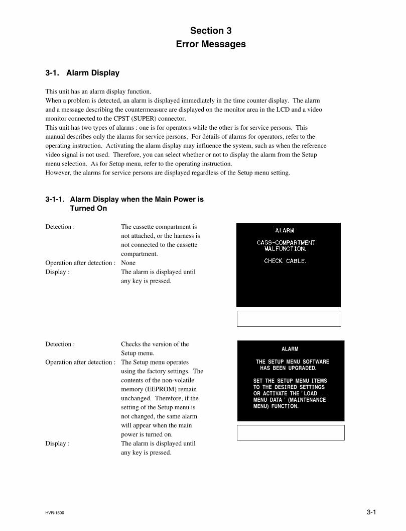
Detection : The cassette compartment isnot attached, or the harness isnot connected to the cassettecompartment.
Operation after detection : NoneDisplay : The alarm is displayed until
any key is pressed.
Detection : Checks the version of theSetup menu.
Operation after detection : The Setup menu operatesusing the factory settings. Thecontents of the non-volatilememory (EEPROM) remainunchanged. Therefore, if thesetting of the Setup menu isnot changed, the same alarmwill appear when the mainpower is turned on.
Display : The alarm is displayed untilany key is pressed.
ALARM
THE SETUP MENU SOFTWARE HAS BEEN UPGRADED.
SET THE SETUP MENU I TEMSTO THE DES I RED SETT I NGSOR ACT I VATE THE ’ LOADMENU DATA ’ (MA I NTENANCEMENU) FUNCT I ON.
3-2 HVR-1500
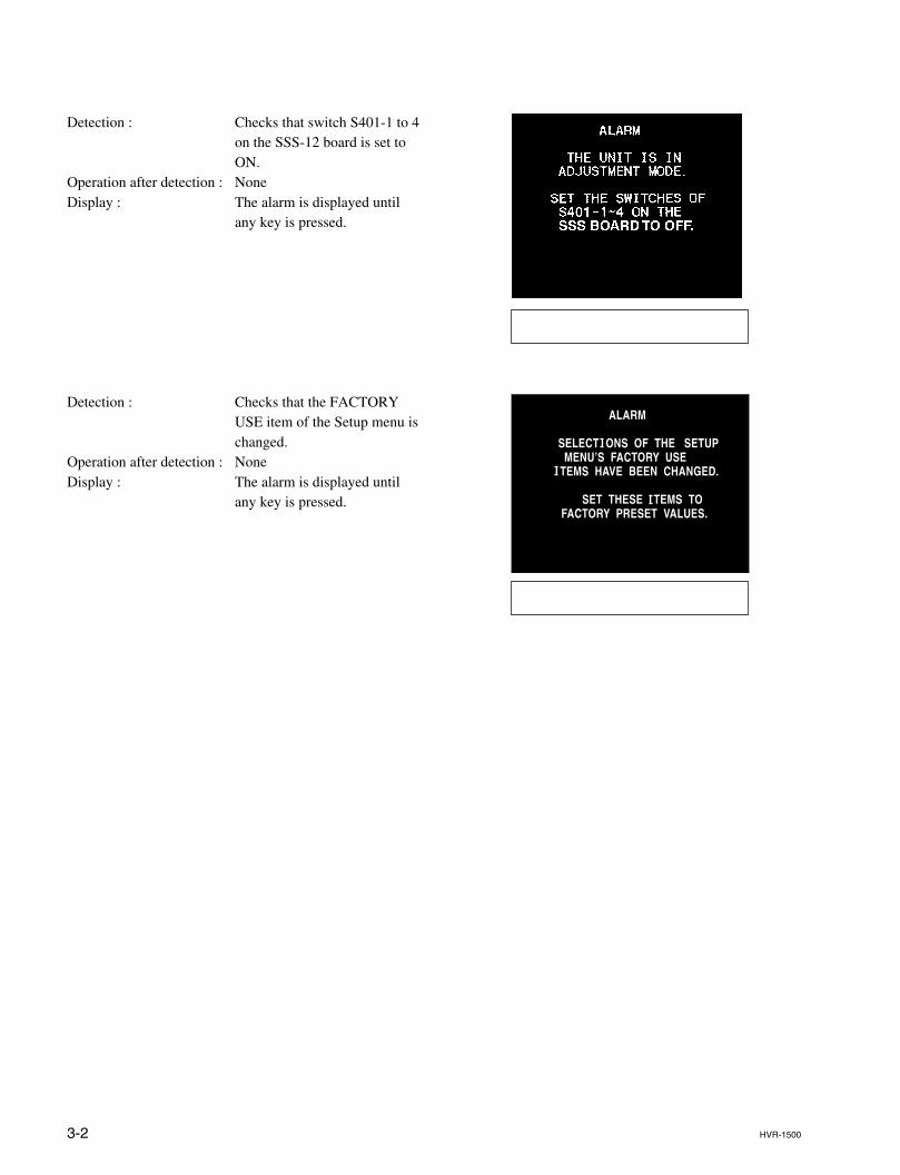
Detection : Checks that switch S401-1 to 4on the SSS-12 board is set toON.
Operation after detection : NoneDisplay : The alarm is displayed until
any key is pressed.
Detection : Checks that the FACTORYUSE item of the Setup menu ischanged.
Operation after detection : NoneDisplay : The alarm is displayed until
any key is pressed.
ALARM
SELECT I ONS OF THE SETUP MENU’S FACTORY USEI TEMS HAVE BEEN CHANGED.
SET THESE I TEMS TO FACTORY PRESET VALUES.
3-3HVR-1500
3-2. Error Codes
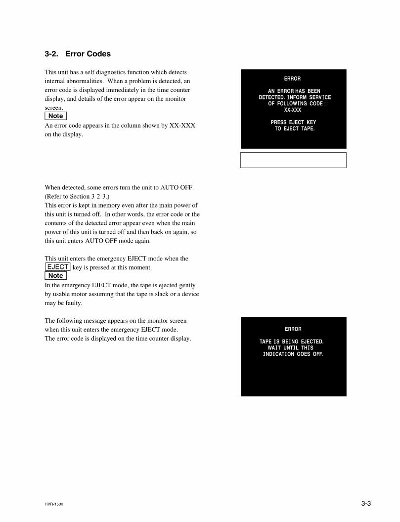
This unit has a self diagnostics function which detectsinternal abnormalities. When a problem is detected, anerror code is displayed immediately in the time counterdisplay, and details of the error appear on the monitorscreen.nAn error code appears in the column shown by XX-XXXon the display.
When detected, some errors turn the unit to AUTO OFF.(Refer to Section 3-2-3.)This error is kept in memory even after the main power ofthis unit is turned off. In other words, the error code or thecontents of the detected error appear even when the mainpower of this unit is turned off and then back on again, sothis unit enters AUTO OFF mode again.
This unit enters the emergency EJECT mode when the[EJECT] key is pressed at this moment.nIn the emergency EJECT mode, the tape is ejected gentlyby usable motor assuming that the tape is slack or a devicemay be faulty.
The following message appears on the monitor screenwhen this unit enters the emergency EJECT mode.The error code is displayed on the time counter display.
ERROR
AN ERROR HAS BEENDETECTED. I NFORM SERV I CE OF FOLLOW I NG CODE : XX-XXX
PRESS EJECT KEY TO EJECT TAPE.
ERROR
TAPE I S BE I NG EJECTED. WA I T UNT I L TH I S I ND I CAT I ON GOES OFF.
3-4 HVR-1500
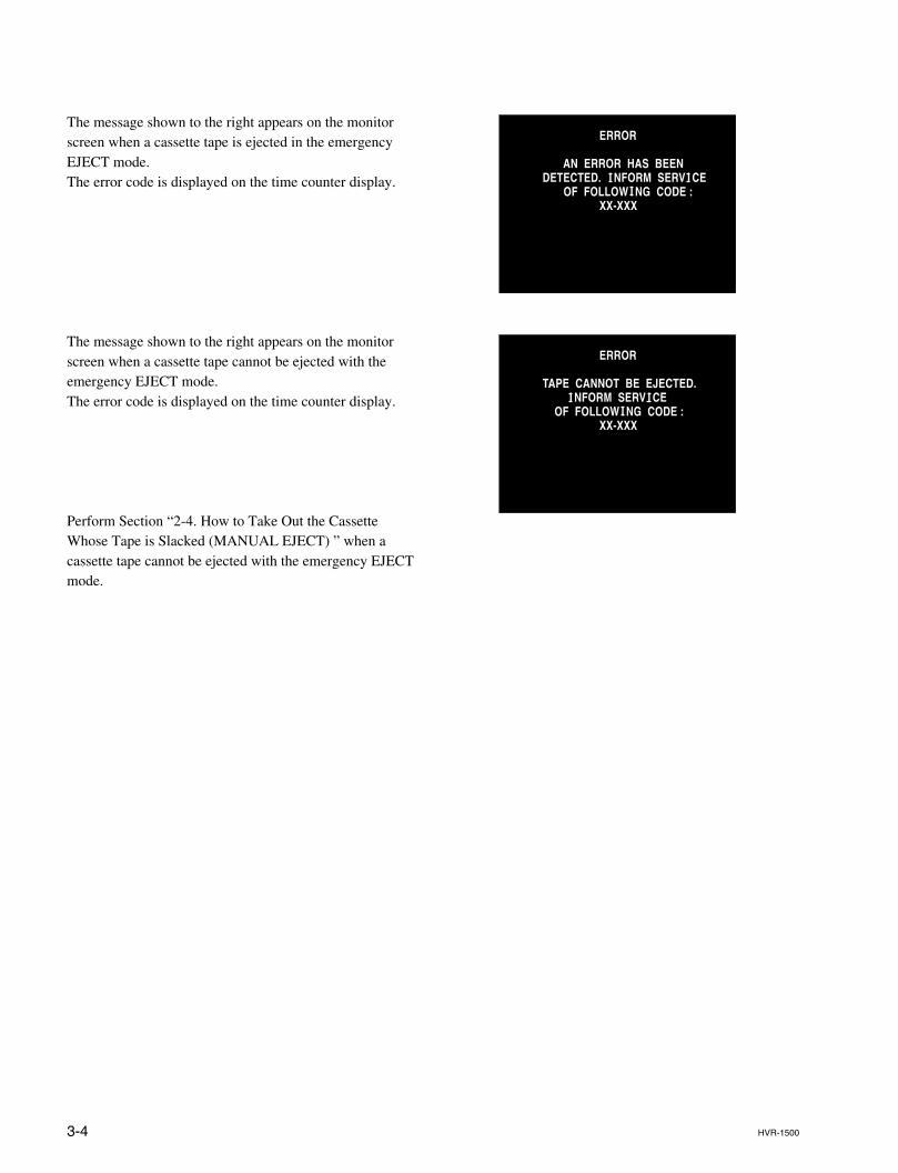
The message shown to the right appears on the monitorscreen when a cassette tape is ejected in the emergencyEJECT mode.The error code is displayed on the time counter display.
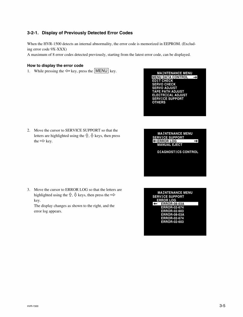
The message shown to the right appears on the monitorscreen when a cassette tape cannot be ejected with theemergency EJECT mode.The error code is displayed on the time counter display.
Perform Section “2-4. How to Take Out the CassetteWhose Tape is Slacked (MANUAL EJECT) ” when acassette tape cannot be ejected with the emergency EJECTmode.
ERROR
AN ERROR HAS BEENDETECTED. I NFORM SERV I CE OF FOLLOW I NG CODE : XX-XXX
ERROR
TAPE CANNOT BE EJECTED. I NFORM SERV I CE OF FOLLOW I NG CODE : XX-XXX
3-5HVR-1500
3-2-1. Display of Previously Detected Error Codes
When the HVR-1500 detects an internal abnormality, the error code is memorized in EEPROM. (Exclud-ing error code 9X-XXX)A maximum of 8 error codes detected previously, starting from the latest error code, can be displayed.
How to display the error code1. While pressing the 7 key, press the [MENU] key.
2. Move the cursor to SERVICE SUPPORT so that theletters are highlighted using the 9, 0 keys, then pressthe 8 key.
3. Move the cursor to ERROR LOG so that the letters arehighlighted using the 9, 0 keys, then press the 8key.The display changes as shown to the right, and theerror log appears.
MA I NTENANCE MENUMENU DATA CONTROLED I T CHECKSERVO CHECKSERVO ADJUSTTAPE PATH ADJUSTELECTR I CAL ADJUSTSERV I CE SUPPORTOTHERS
MA I NTENANCE MENUSERV I CE SUPPORT ERROR LOG MANUAL EJECT
D I AGNOST I CS CONTROL
MA I NTENANCE MENUSERV I CE SUPPORT ERROR LOG ERROR-08-03A ERROR-02-674 ERROR-02-603 ERROR-08-03A ERROR-02-674 ERROR-02-603
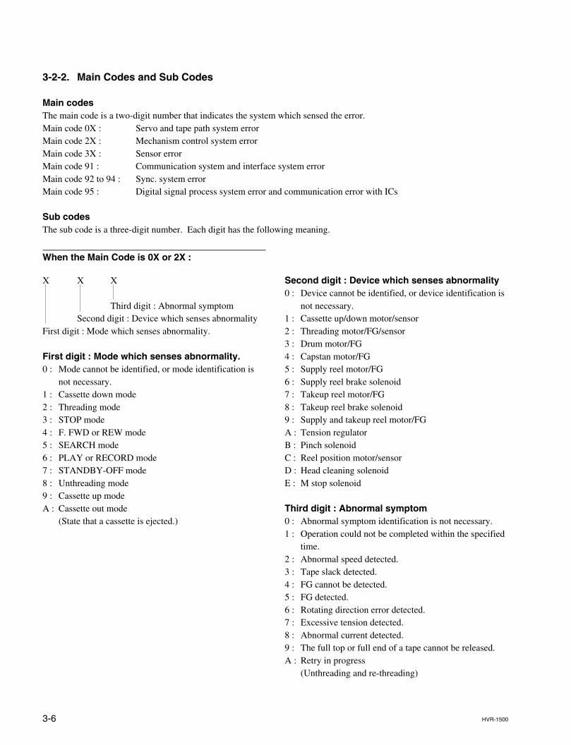
3-6 HVR-1500
3-2-2. Main Codes and Sub Codes
Main codesThe main code is a two-digit number that indicates the system which sensed the error.Main code 0X : Servo and tape path system errorMain code 2X : Mechanism control system errorMain code 3X : Sensor errorMain code 91 : Communication system and interface system errorMain code 92 to 94 : Sync. system errorMain code 95 : Digital signal process system error and communication error with ICs
Sub codesThe sub code is a three-digit number. Each digit has the following meaning.
When the Main Code is 0X or 2X :
X X X
Third digit : Abnormal symptomSecond digit : Device which senses abnormality
First digit : Mode which senses abnormality.
First digit : Mode which senses abnormality.0 : Mode cannot be identified, or mode identification is
not necessary.1 : Cassette down mode2 : Threading mode3 : STOP mode4 : F. FWD or REW mode5 : SEARCH mode6 : PLAY or RECORD mode7 : STANDBY-OFF mode8 : Unthreading mode9 : Cassette up modeA : Cassette out mode
(State that a cassette is ejected.)
Second digit : Device which senses abnormality0 : Device cannot be identified, or device identification is
not necessary.1 : Cassette up/down motor/sensor2 : Threading motor/FG/sensor3 : Drum motor/FG4 : Capstan motor/FG5 : Supply reel motor/FG6 : Supply reel brake solenoid7 : Takeup reel motor/FG8 : Takeup reel brake solenoid9 : Supply and takeup reel motor/FGA : Tension regulatorB : Pinch solenoidC : Reel position motor/sensorD : Head cleaning solenoidE : M stop solenoid
Third digit : Abnormal symptom0 : Abnormal symptom identification is not necessary.1 : Operation could not be completed within the specified
time.2 : Abnormal speed detected.3 : Tape slack detected.4 : FG cannot be detected.5 : FG detected.6 : Rotating direction error detected.7 : Excessive tension detected.8 : Abnormal current detected.9 : The full top or full end of a tape cannot be released.A : Retry in progress
(Unthreading and re-threading)
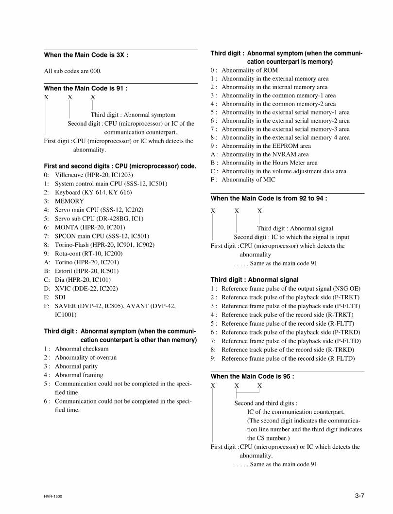
3-7HVR-1500
Third digit : Abnormal symptom (when the communi-cation counterpart is memory)
0 : Abnormality of ROM1 : Abnormality in the external memory area2 : Abnormality in the internal memory area3 : Abnormality in the common memory-1 area4 : Abnormality in the common memory-2 area5 : Abnormality in the external serial memory-1 area6 : Abnormality in the external serial memory-2 area7 : Abnormality in the external serial memory-3 area8 : Abnormality in the external serial memory-4 area9 : Abnormality in the EEPROM areaA : Abnormality in the NVRAM areaB : Abnormality in the Hours Meter areaC : Abnormality in the volume adjustment data areaF : Abnormality of MIC
When the Main Code is from 92 to 94 :
X X X
Third digit : Abnormal signalSecond digit : IC to which the signal is input
First digit :CPU (microprocessor) which detects theabnormality
. . . . . Same as the main code 91
Third digit : Abnormal signal1 : Reference frame pulse of the output signal (NSG OE)2 : Reference track pulse of the playback side (P-TRKT)3 : Reference frame pulse of the playback side (P-FLTT)4 : Reference track pulse of the record side (R-TRKT)5 : Reference frame pulse of the record side (R-FLTT)6 : Reference track pulse of the playback side (P-TRKD)7: Reference frame pulse of the playback side (P-FLTD)8: Reference track pulse of the record side (R-TRKD)9: Reference frame pulse of the record side (R-FLTD)
When the Main Code is 95 :X X X
Second and third digits :IC of the communication counterpart.(The second digit indicates the communica-tion line number and the third digit indicatesthe CS number.)
First digit :CPU (microprocessor) or IC which detects theabnormality.
. . . . . Same as the main code 91
When the Main Code is 3X :
All sub codes are 000.
When the Main Code is 91 :X X X
Third digit : Abnormal symptomSecond digit :CPU (microprocessor) or IC of the
communication counterpart.First digit :CPU (microprocessor) or IC which detects the
abnormality.
First and second digits : CPU (microprocessor) code.0: Villeneuve (HPR-20, IC1203)1: System control main CPU (SSS-12, IC501)2: Keyboard (KY-614, KY-616)3: MEMORY4: Servo main CPU (SSS-12, IC202)5: Servo sub CPU (DR-428BG, IC1)6: MONTA (HPR-20, IC201)7: SPCON main CPU (SSS-12, IC501)8: Torino-Flash (HPR-20, IC901, IC902)9: Rota-cont (RT-10, IC200)A: Torino (HPR-20, IC701)B: Estoril (HPR-20, IC501)C: Dia (HPR-20, IC101)D: XVIC (DDE-22, IC202)E: SDIF: SAVER (DVP-42, IC805), AVANT (DVP-42,
IC1001)
Third digit : Abnormal symptom (when the communi-cation counterpart is other than memory)
1 : Abnormal checksum2 : Abnormality of overrun3 : Abnormal parity4 : Abnormal framing5 : Communication could not be completed in the speci-
fied time.6 : Communication could not be completed in the speci-
fied time.
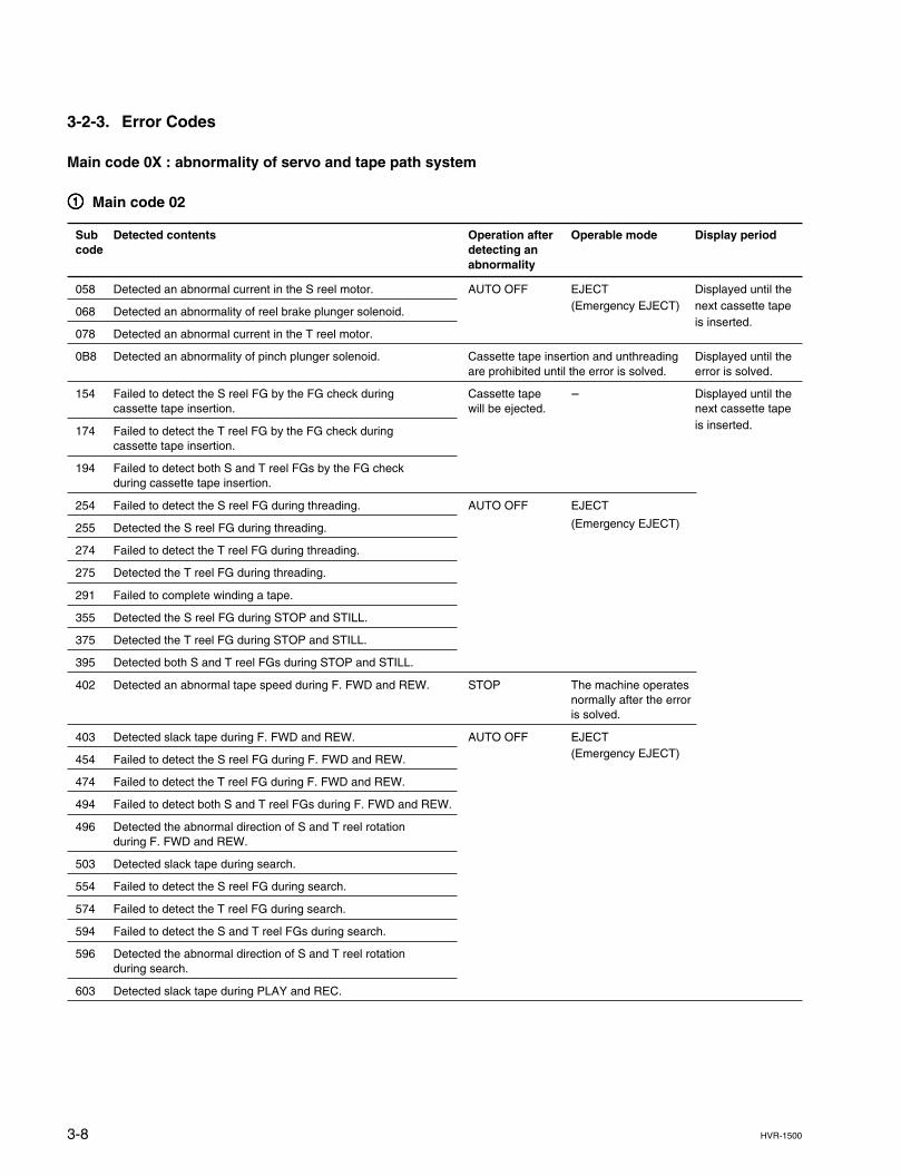
3-8 HVR-1500
3-2-3. Error Codes
Main code 0X : abnormality of servo and tape path system
11111 Main code 02
Sub Detected contents Operation after Operable mode Display periodcode detecting an
abnormality
058 Detected an abnormal current in the S reel motor. AUTO OFF EJECT Displayed until the
068 Detected an abnormality of reel brake plunger solenoid. (Emergency EJECT) next cassette tape
078 Detected an abnormal current in the T reel motor.is inserted.
0B8 Detected an abnormality of pinch plunger solenoid. Cassette tape insertion and unthreading Displayed until theare prohibited until the error is solved. error is solved.
154 Failed to detect the S reel FG by the FG check during Cassette tape _ Displayed until thecassette tape insertion. will be ejected. next cassette tape
174 Failed to detect the T reel FG by the FG check during is inserted.
cassette tape insertion.
194 Failed to detect both S and T reel FGs by the FG checkduring cassette tape insertion.
254 Failed to detect the S reel FG during threading. AUTO OFF EJECT
255 Detected the S reel FG during threading. (Emergency EJECT)
274 Failed to detect the T reel FG during threading.
275 Detected the T reel FG during threading.
291 Failed to complete winding a tape.
355 Detected the S reel FG during STOP and STILL.
375 Detected the T reel FG during STOP and STILL.
395 Detected both S and T reel FGs during STOP and STILL.
402 Detected an abnormal tape speed during F. FWD and REW. STOP The machine operatesnormally after the erroris solved.
403 Detected slack tape during F. FWD and REW. AUTO OFF EJECT
454 Failed to detect the S reel FG during F. FWD and REW. (Emergency EJECT)
474 Failed to detect the T reel FG during F. FWD and REW.
494 Failed to detect both S and T reel FGs during F. FWD and REW.
496 Detected the abnormal direction of S and T reel rotationduring F. FWD and REW.
503 Detected slack tape during search.
554 Failed to detect the S reel FG during search.
574 Failed to detect the T reel FG during search.
594 Failed to detect the S and T reel FGs during search.
596 Detected the abnormal direction of S and T reel rotationduring search.
603 Detected slack tape during PLAY and REC.
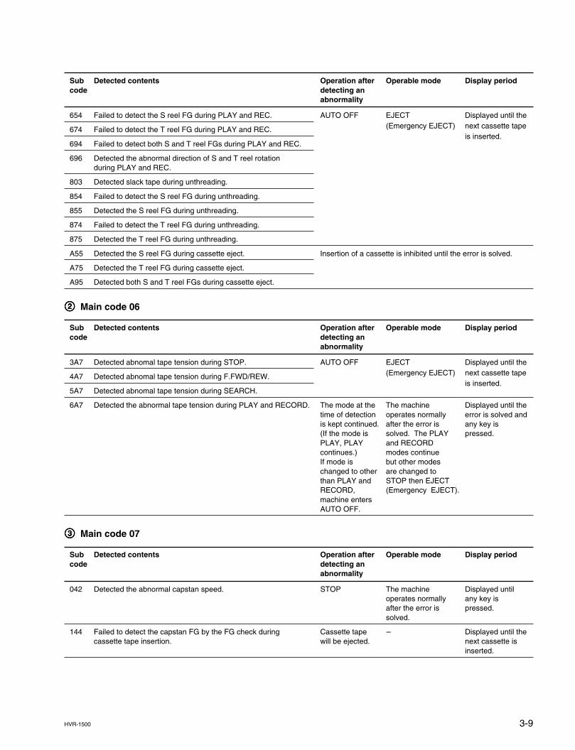
3-9HVR-1500
Sub Detected contents Operation after Operable mode Display periodcode detecting an
abnormality
654 Failed to detect the S reel FG during PLAY and REC. AUTO OFF EJECT Displayed until the
674 Failed to detect the T reel FG during PLAY and REC. (Emergency EJECT) next cassette tape
694 Failed to detect both S and T reel FGs during PLAY and REC.is inserted.
696 Detected the abnormal direction of S and T reel rotationduring PLAY and REC.
803 Detected slack tape during unthreading.
854 Failed to detect the S reel FG during unthreading.
855 Detected the S reel FG during unthreading.
874 Failed to detect the T reel FG during unthreading.
875 Detected the T reel FG during unthreading.
A55 Detected the S reel FG during cassette eject. Insertion of a cassette is inhibited until the error is solved.
A75 Detected the T reel FG during cassette eject.
A95 Detected both S and T reel FGs during cassette eject.
22222 Main code 06
Sub Detected contents Operation after Operable mode Display periodcode detecting an
abnormality
3A7 Detected abnomal tape tension during STOP. AUTO OFF EJECT Displayed until the
4A7 Detected abnomal tape tension during F.FWD/REW. (Emergency EJECT) next cassette tape
5A7 Detected abnomal tape tension during SEARCH.is inserted.
6A7 Detected the abnormal tape tension during PLAY and RECORD. The mode at the The machine Displayed until thetime of detection operates normally error is solved andis kept continued. after the error is any key is(If the mode is solved. The PLAY pressed.PLAY, PLAY and RECORDcontinues.) modes continueIf mode is but other modeschanged to other are changed tothan PLAY and STOP then EJECTRECORD, (Emergency EJECT).machine entersAUTO OFF.
33333 Main code 07
Sub Detected contents Operation after Operable mode Display periodcode detecting an
abnormality
042 Detected the abnormal capstan speed. STOP The machine Displayed untiloperates normally any key isafter the error is pressed.solved.
144 Failed to detect the capstan FG by the FG check during Cassette tape _ Displayed until thecassette tape insertion. will be ejected. next cassette is
inserted.
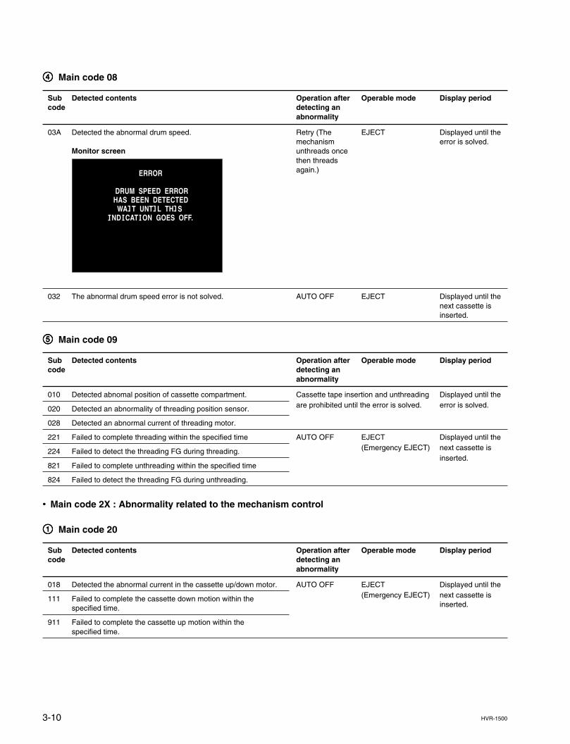
3-10 HVR-1500
44444 Main code 08
Sub Detected contents Operation after Operable mode Display periodcode detecting an
abnormality
03A Detected the abnormal drum speed. Retry (The EJECT Displayed until themechanism error is solved.
Monitor screen unthreads oncethen threadsagain.)
032 The abnormal drum speed error is not solved. AUTO OFF EJECT Displayed until thenext cassette isinserted.
55555 Main code 09
Sub Detected contents Operation after Operable mode Display periodcode detecting an
abnormality
010 Detected abnomal position of cassette compartment. Cassette tape insertion and unthreading Displayed until the
020 Detected an abnormality of threading position sensor. are prohibited until the error is solved. error is solved.
028 Detected an abnormal current of threading motor.
221 Failed to complete threading within the specified time AUTO OFF EJECT Displayed until the
224 Failed to detect the threading FG during threading. (Emergency EJECT) next cassette is
821 Failed to complete unthreading within the specified timeinserted.
824 Failed to detect the threading FG during unthreading.
..... Main code 2X : Abnormality related to the mechanism control
11111 Main code 20
Sub Detected contents Operation after Operable mode Display periodcode detecting an
abnormality
018 Detected the abnormal current in the cassette up/down motor. AUTO OFF EJECT Displayed until the
111 Failed to complete the cassette down motion within the (Emergency EJECT) next cassette is
specified time. inserted.
911 Failed to complete the cassette up motion within thespecified time.
ERROR
DRUM SPEED ERRORHAS BEEN DETECTED WA I T UNT I L TH I S
I ND I CAT I ON GOES OFF.
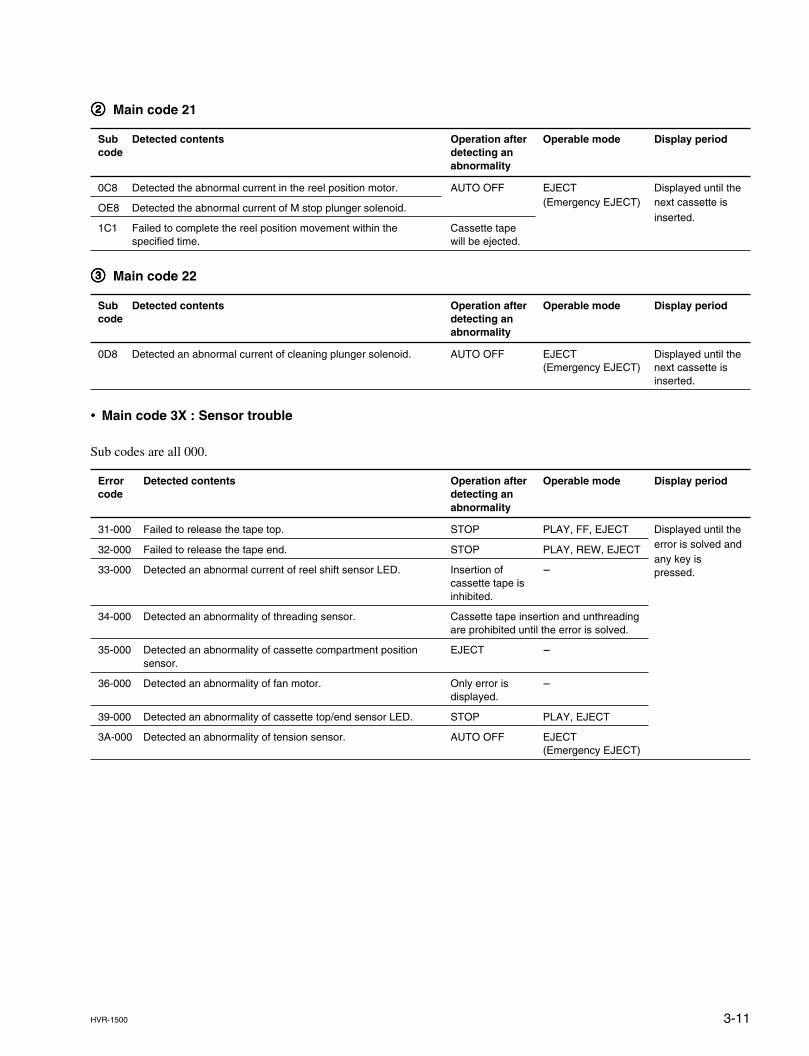
3-11HVR-1500
22222 Main code 21
Sub Detected contents Operation after Operable mode Display periodcode detecting an
abnormality
0C8 Detected the abnormal current in the reel position motor. AUTO OFF EJECT Displayed until the
OE8 Detected the abnormal current of M stop plunger solenoid. (Emergency EJECT) next cassette is
1C1 Failed to complete the reel position movement within the Cassette tapeinserted.
specified time. will be ejected.
33333 Main code 22
Sub Detected contents Operation after Operable mode Display periodcode detecting an
abnormality
0D8 Detected an abnormal current of cleaning plunger solenoid. AUTO OFF EJECT Displayed until the(Emergency EJECT) next cassette is
inserted.
..... Main code 3X : Sensor trouble
Sub codes are all 000.
Error Detected contents Operation after Operable mode Display periodcode detecting an
abnormality
31-000 Failed to release the tape top. STOP PLAY, FF, EJECT Displayed until the
32-000 Failed to release the tape end. STOP PLAY, REW, EJECT error is solved and
33-000 Detected an abnormal current of reel shift sensor LED. Insertion of _any key is
cassette tape ispressed.
inhibited.
34-000 Detected an abnormality of threading sensor. Cassette tape insertion and unthreadingare prohibited until the error is solved.
35-000 Detected an abnormality of cassette compartment position EJECT _sensor.
36-000 Detected an abnormality of fan motor. Only error is _displayed.
39-000 Detected an abnormality of cassette top/end sensor LED. STOP PLAY, EJECT
3A-000 Detected an abnormality of tension sensor. AUTO OFF EJECT(Emergency EJECT)
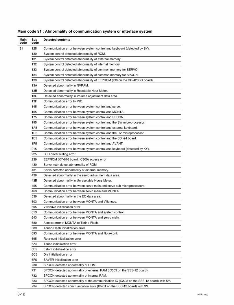
3-12 HVR-1500
Main code 91 : Abnormality of communication system or interface system
Main Sub Detected contentscode code
91 125 Communication error between system control and keyboard (detected by SY).
130 System control detected abnormality of ROM.
131 System control detected abnormality of external memory.
132 System control detected abnormality of internal memory.
133 System control detected abnormality of common memory for SERVO.
134 System control detected abnormality of common memory for SPCON.
139 System control detected abnormality of EEPROM (IC8 on the DR-428BG board).
13A Detected abnormality in NVRAM.
13B Detected abnormality in Resetable Hour Meter.
13C Detected abnormality in Volume adjustment data area.
13F Communication error to MIC.
145 Communication error between system control and servo.
165 Communication error between system control and MONTA.
175 Communication error between system control and SPCON.
195 Communication error between system control and the SW microprocessor.
1A5 Communication error between system control and external keyboard.
1D5 Communication error between system control and the DV microprocessor.
1E5 Communication error between system control and the SDI-94 board.
1F5 Communication error between system control and AVANT.
215 Communication error between system control and keyboard (detected by KY).
225 LCD driver writing error
239 EEPROM (KY-616 board, IC300) access error
430 Servo main detect abnormality of ROM.
431 Servo detected abnormality of external memory.
439 Detected abnormality in the servo adjustment data area.
43B Detected abnormality in Unresetable Hours Meter.
455 Communication error between servo main and servo sub microprocessors.
463 Communication error between servo main and MONTA.
539 Detected abnormality in the EQ data area.
603 Communication error between MONTA and Villenuve.
605 Villenuve initialization error
613 Communication error between MONTA and system control.
643 Communication error between MONTA and servo main.
680 Access error of MONTA to Torino-Flash.
689 Torino-Flash initialization error
693 Communication error between MONTA and Rota-cont.
695 Rota-cont initialization error
6A5 Torino initialization error
6B5 Estoril initialization error
6C5 Dia initialization error
6F5 SAVER initialization error
730 SPCON detected abnormality of ROM.
731 SPCON detected abnormality of external RAM (IC503 on the SSS-12 board).
732 SPCON detected abnormality of internal RAM.
733 SPCON detected abnormality of the communication IC (IC503 on the SSS-12 board) with SY.
734 SPCON detected communication error (IC401 on the SSS-12 board) with SV.
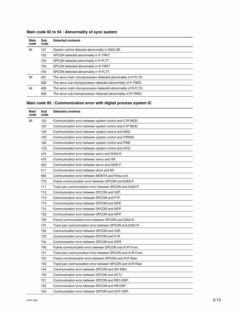
3-13HVR-1500
Main code 92 to 94 : Abnormality of sync system
Main Sub Detected contentscode code
92 101 System control detected abnormality in NSG OE.
702 SPCON detected abnormality in P-TRKT.
703 SPCON detected abnormality in P-FLTT.
704 SPCON detected abnormality in R-TRKT.
705 SPCON detected abnormality in R-FLTT.
93 407 The servo main microprocessor detected abnormality of P-FLTD.
506 The servo sub microprocessor detected abnormality of P-TRKD.
94 409 The servo main microprocessor detected abnormality of R-FLTD.
508 The servo sub microprocessor detected abnormality of R-TRKD.
Main code 95 : Communication error with digital process system IC
Main Sub Detected contentscode code
95 120 Communication error between system control and C1R MOD.
122 Communication error between system control and C1P MOD.
12A Communication error between system control and NSG.
12C Communication error between system control and VPRAD.
190 Communication error between system control and FINE.
1C0 Communication error between system control and XVIC.
415 Communication error between servo and DIAS-R.
416 Communication error between servo and HIF.
423 Communication error between servo and DIAS-P.
511 Communication error between drum and M1.
693 Communication error between MONTA and Rota-cont.
710 Frame communication error between SPCON and DIAS-P.
711 Track pair communication error between SPCON and DIAS-P.
712 Communication error between SPCON and V2P.
713 Communication error between SPCON and F1P.
714 Communication error between SPCON and SIFE.
715 Communication error between SPCON and SIFP.
720 Communication error between SPCON and AIFP.
730 Frame communication error between SPCON and DIAS-R.
731 Track pair communication error between SPCON and DIAS-R.
732 Communication error between SPCON and V2R.
733 Communication error between SPCON and F1R.
734 Communication error between SPCON and SIFR.
740 Frame communication error between SPCON and A1R Front.
741 Track pair communication error between SPCON and A1R Front.
742 Frame communication error between SPCON and A1R Rear.
743 Track pair communication error between SPCON and A1R Rear.
744 Communication error between SPCON and AIF-INDI.
745 Communication error between SPCON and ACTL.
751 Communication error between SPCON and REC-DSP.
752 Communication error between SPCON and PB-DSP.
753 Communication error between SPCON and OUT-DSP.
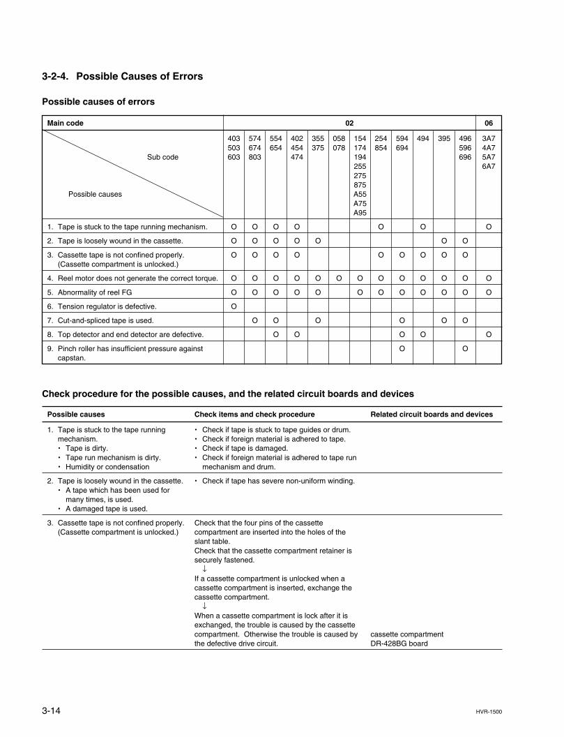
3-14 HVR-1500
3-2-4. Possible Causes of Errors
Possible causes of errors
Main code 02 06
403 574 554 402 355 058 154 254 594 494 395 496 3A7503 674 654 454 375 078 174 854 694 596 4A7
Sub code 603 803 474 194 696 5A7255 6A7275875
Possible causes A55A75A95
1. Tape is stuck to the tape running mechanism. O O O O O O O
2. Tape is loosely wound in the cassette. O O O O O O O
3. Cassette tape is not confined properly. O O O O O O O O O(Cassette compartment is unlocked.)
4. Reel motor does not generate the correct torque. O O O O O O O O O O O O O
5. Abnormality of reel FG O O O O O O O O O O O O
6. Tension regulator is defective. O
7. Cut-and-spliced tape is used. O O O O O O
8. Top detector and end detector are defective. O O O O O
9. Pinch roller has insufficient pressure against O Ocapstan.
Check procedure for the possible causes, and the related circuit boards and devices
Possible causes Check items and check procedure Related circuit boards and devices
1. Tape is stuck to the tape running . Check if tape is stuck to tape guides or drum.mechanism. . Check if foreign material is adhered to tape.. Tape is dirty. . Check if tape is damaged.. Tape run mechanism is dirty. . Check if foreign material is adhered to tape run. Humidity or condensation mechanism and drum.
2. Tape is loosely wound in the cassette. . Check if tape has severe non-uniform winding.. A tape which has been used for
many times, is used.. A damaged tape is used.
3. Cassette tape is not confined properly. Check that the four pins of the cassette(Cassette compartment is unlocked.) compartment are inserted into the holes of the
slant table.Check that the cassette compartment retainer issecurely fastened.
↓If a cassette compartment is unlocked when acassette compartment is inserted, exchange thecassette compartment.
↓When a cassette compartment is lock after it isexchanged, the trouble is caused by the cassettecompartment. Otherwise the trouble is caused by cassette compartmentthe defective drive circuit. DR-428BG board
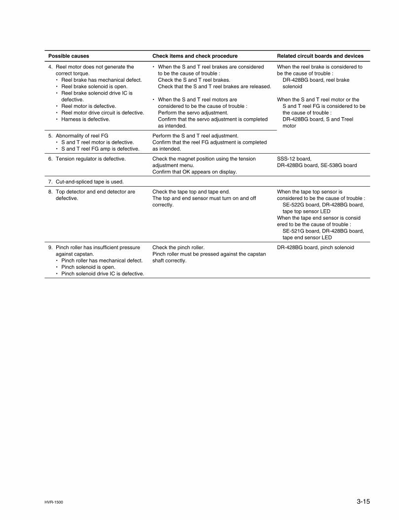
3-15HVR-1500
Possible causes Check items and check procedure Related circuit boards and devices
4. Reel motor does not generate the . When the S and T reel brakes are considered When the reel brake is considered tocorrect torque. to be the cause of trouble : be the cause of trouble :. Reel brake has mechanical defect. Check the S and T reel brakes. DR-428BG board, reel brake. Reel brake solenoid is open. Check that the S and T reel brakes are released. solenoid. Reel brake solenoid drive IC is
defective. . When the S and T reel motors are When the S and T reel motor or the. Reel motor is defective. considered to be the cause of trouble : S and T reel FG is considered to be. Reel motor drive circuit is defective. Perform the servo adjustment. the cause of trouble :. Harness is defective. Confirm that the servo adjustment is completed DR-428BG board, S and Treel
as intended. motor
5. Abnormality of reel FG Perform the S and T reel adjustment.. S and T reel motor is defective. Confirm that the reel FG adjustment is completed. S and T reel FG amp is defective. as intended.
6. Tension regulator is defective. Check the magnet position using the tension SSS-12 board,adjustment menu. DR-428BG board, SE-538G boardConfirm that OK appears on display.
7. Cut-and-spliced tape is used.
8. Top detector and end detector are Check the tape top and tape end. When the tape top sensor isdefective. The top and end sensor must turn on and off considered to be the cause of trouble :
correctly. SE-522G board, DR-428BG board,tape top sensor LED
When the tape end sensor is considered to be the cause of trouble :
SE-521G board, DR-428BG board,tape end sensor LED
9. Pinch roller has insufficient pressure Check the pinch roller. DR-428BG board, pinch solenoidagainst capstan. Pinch roller must be pressed against the capstan. Pinch roller has mechanical defect. shaft correctly.. Pinch solenoid is open.. Pinch solenoid drive IC is defective.

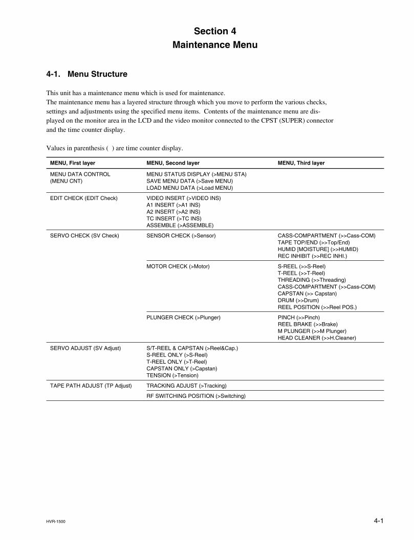
4-1HVR-1500
4-1. Menu Structure
This unit has a maintenance menu which is used for maintenance.The maintenance menu has a layered structure through which you move to perform the various checks,settings and adjustments using the specified menu items. Contents of the maintenance menu are dis-played on the monitor area in the LCD and the video monitor connected to the CPST (SUPER) connectorand the time counter display.
Values in parenthesis ( ) are time counter display.
MENU, First layer MENU, Second layer MENU, Third layer
MENU DATA CONTROL MENU STATUS DISPLAY (>MENU STA)(MENU CNT) SAVE MENU DATA (>Save MENU)
LOAD MENU DATA (>Load MENU)
EDIT CHECK (EDIT Check) VIDEO INSERT (>VIDEO INS)A1 INSERT (>A1 INS)A2 INSERT (>A2 INS)TC INSERT (>TC INS)ASSEMBLE (>ASSEMBLE)
SERVO CHECK (SV Check) SENSOR CHECK (>Sensor) CASS-COMPARTMENT (>>Cass-COM)TAPE TOP/END (>>Top/End)HUMID [MOISTURE] (>>HUMID)REC INHIBIT (>>REC INHI.)
MOTOR CHECK (>Motor) S-REEL (>>S-Reel)T-REEL (>>T-Reel)THREADING (>>Threading)CASS-COMPARTMENT (>>Cass-COM)CAPSTAN (>> Capstan)DRUM (>>Drum)REEL POSITION (>>Reel POS.)
PLUNGER CHECK (>Plunger) PINCH (>>Pinch)REEL BRAKE (>>Brake)M PLUNGER (>>M Plunger)HEAD CLEANER (>>H.Cleaner)
SERVO ADJUST (SV Adjust) S/T-REEL & CAPSTAN (>Reel&Cap.)S-REEL ONLY (>S-Reel)T-REEL ONLY (>T-Reel)CAPSTAN ONLY (>Capstan)TENSION (>Tension)
TAPE PATH ADJUST (TP Adjust) TRACKING ADJUST (>Tracking)
RF SWITCHING POSITION (>Switching)
Section 4Maintenance Menu
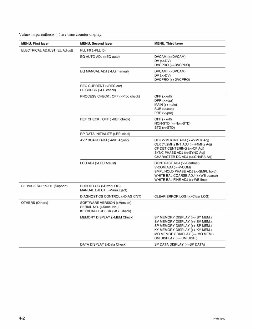
4-2 HVR-1500
Values in parenthesis ( ) are time counter display.
MENU, First layer MENU, Second layer MENU, Third layer
ELECTRICAL ADJUST (EL Adjust) PLL F0 (>PLL f0)
EQ AUTO ADJ (>EQ auto) DVCAM (>>DVCAM)DV (>>DV)DVCPRO (>>DVCPRO)
EQ MANUAL ADJ (>EQ manual) DVCAM (>>DVCAM)DV (>>DV)DVCPRO (>>DVCPRO)
REC CURRENT (>REC cur)FE CHECK (>FE check)
PROCESS CHECK : OFF (>Proc check) OFF (>>off)DPR (>>dpr)MAIN (>>main)SUB (>>sub)PRE (>>pre)
REF CHECK : OFF (>REF check) OFF (>>off)NON-STD (>>Non-STD)STD (>>STD)
RP DATA INITIALIZE (>RP initial)
AVP BOARD ADJ (>AVP Adjust) CLK 27MHz INT ADJ (>>27MHz Adj)CLK 74/2MHz INT ADJ (>>74MHz Adj)CF DET CENTERING (>>CF Adj)SYNC PHASE ADJ (>>SYNC Adj)CHARACTER DC ADJ (>>CHARA Adj)
LCD ADJ (>LCD Adjust) CONTRAST ADJ (>>Contrast)V-COM ADJ (>>V-COM)SMPL HOLD PHASE ADJ (>>SMPL hold)WHITE BAL COARSE ADJ (>>WB coarse)WHITE BAL FINE ADJ (>>WB fine)
SERVICE SUPPORT (Support) ERROR LOG (>Error LOG)MANUAL EJECT (>Manu.Eject)
DIAGNOSTICS CONTROL (>DIAG CNT) CLEAR ERROR LOG (>>Clear LOG)
OTHERS (Others) SOFTWARE VERSION (>Version)SERIAL NO. (>Serial No.)KEYBOARD CHECK (>KY Check)
MEMORY DISPLAY (>MEM Check) SY MEMORY DISPLAY (>> SY MEM.)SV MEMORY DISPLAY (>> SV MEM.)SP MEMORY DISPLAY (>> SP MEM.)KY MEMORY DISPLAY (>> KY MEM.)MO MEMORY DIAPLAY (>> MO MEM.)CM DISPLAY (>> CM DISP.)
DATA DISPLAY (>Data Check) SP DATA DISPLAY (>>SP DATA)
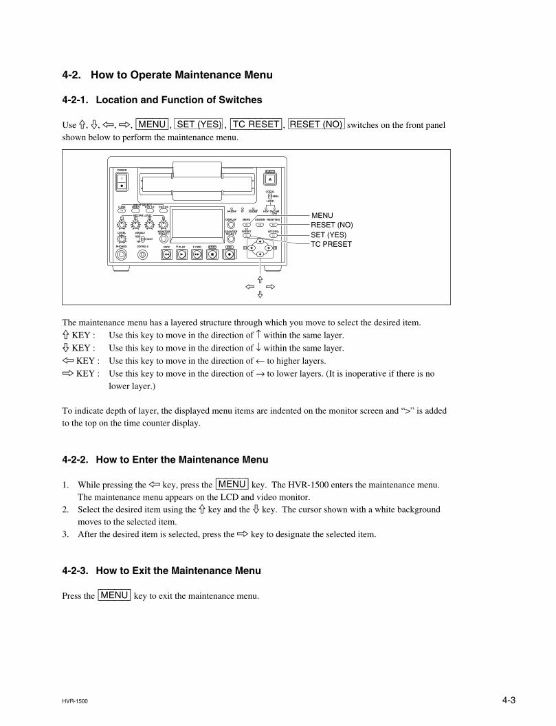
4-3HVR-1500
4-2. How to Operate Maintenance Menu
4-2-1. Location and Function of Switches
Use 9, 0, 7, 8, [MENU], SET (YES) , [TC|RESET], RESET (NO) switches on the front panelshown below to perform the maintenance menu.
The maintenance menu has a layered structure through which you move to select the desired item.9 KEY : Use this key to move in the direction of ↑ within the same layer.
0 KEY : Use this key to move in the direction of ↓ within the same layer.
7 KEY : Use this key to move in the direction of ← to higher layers.8 KEY : Use this key to move in the direction of → to lower layers. (It is inoperative if there is no
lower layer.)
To indicate depth of layer, the displayed menu items are indented on the monitor screen and “>” is addedto the top on the time counter display.
4-2-2. How to Enter the Maintenance Menu
1. While pressing the 7 key, press the [MENU] key. The HVR-1500 enters the maintenance menu.The maintenance menu appears on the LCD and video monitor.
2. Select the desired item using the 9 key and the 0 key. The cursor shown with a white backgroundmoves to the selected item.
3. After the desired item is selected, press the 8 key to designate the selected item.
4-2-3. How to Exit the Maintenance Menu
Press the [MENU] key to exit the maintenance menu.
MENURESET (NO)SET (YES)TC PRESET
9
07 8
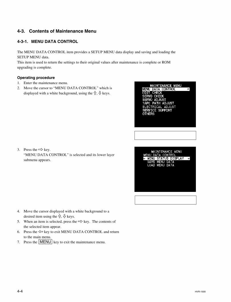
4-4 HVR-1500
4-3. Contents of Maintenance Menu
4-3-1. MENU DATA CONTROL
The MENU DATA CONTROL item provides a SETUP MENU data display and saving and loading theSETUP MENU data.This item is used to return the settings to their original values after maintenance is complete or ROMupgrading is complete.
Operating procedure1. Enter the maintenance menu.2. Move the cursor to “MENU DATA CONTROL” which is
displayed with a white background, using the 9, 0 keys.
3. Press the 8 key.“MENU DATA CONTROL” is selected and its lower layersubmenu appears.
4. Move the cursor displayed with a white background to adesired item using the 9, 0 keys.
5. When an item is selected, press the 8 key. The contents ofthe selected item appear.
6. Press the 7 key to exit MENU DATA CONTROL and returnto the main menu.
7. Press the [MENU] key to exit the maintenance menu.
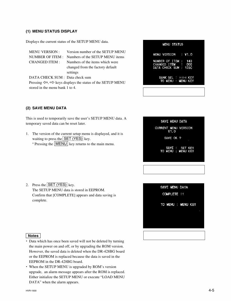
4-5HVR-1500
(1) MENU STATUS DISPLAY
Displays the current status of the SETUP MENU data.
MENU VERSION : Version number of the SETUP MENUNUMBER OF ITEM : Numbers of the SETUP MENU itemsCHANGED ITEM : Numbers of the items which were
changed from the factory defaultsettings
DATA CHECK SUM : Data check sumPressing 7, 8 keys displays the status of the SETUP MENUstored in the menu bank 1 to 4.
(2) SAVE MENU DATA
This is used to temporarily save the user’s SETUP MENU data. Atemporary saved data can be reset later.
1. The version of the current setup menu is displayed, and it iswaiting to press the SET (YES) key.* Pressing the [MENU] key returns to the main menu.
2. Press the SET (YES) key.The SETUP MENU data is stored in EEPROM.Confirm that [COMPLETE] appears and data saving iscomplete.
m. Data which has once been saved will not be deleted by turning
the main power on and off, or by upgrading the ROM version.However, the saved data is deleted when the DR-428BG boardor the EEPROM is replaced because the data is saved in theEEPROM in the DR-428BG board.
. When the SETUP MENU is upgraded by ROM’s versionupgrade, an alarm message appears after the ROM is replaced.Either initialize the SETUP MENU or execute “LOAD MENUDATA” when the alarm appears.
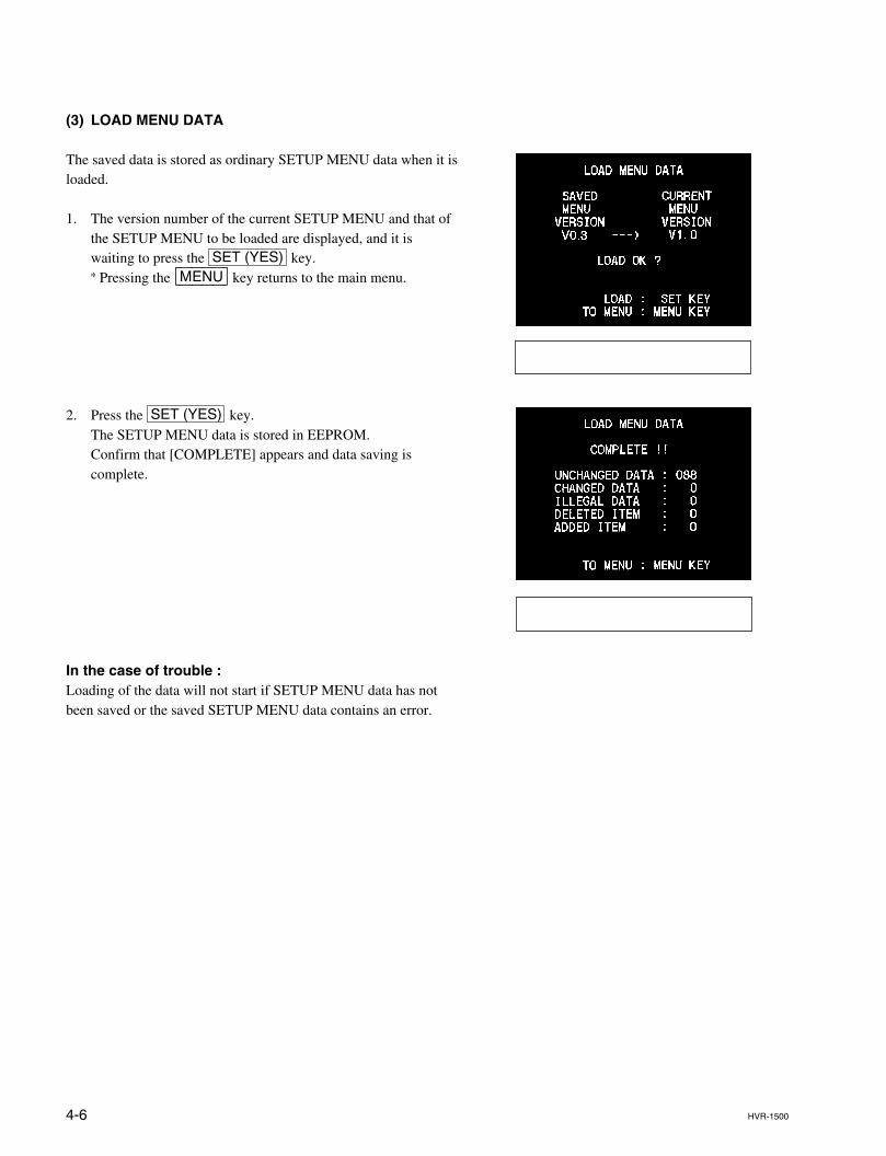
4-6 HVR-1500
(3) LOAD MENU DATA
The saved data is stored as ordinary SETUP MENU data when it isloaded.
1. The version number of the current SETUP MENU and that ofthe SETUP MENU to be loaded are displayed, and it iswaiting to press the SET (YES) key.* Pressing the [MENU] key returns to the main menu.
2. Press the SET (YES) key.The SETUP MENU data is stored in EEPROM.Confirm that [COMPLETE] appears and data saving iscomplete.
In the case of trouble :Loading of the data will not start if SETUP MENU data has notbeen saved or the saved SETUP MENU data contains an error.
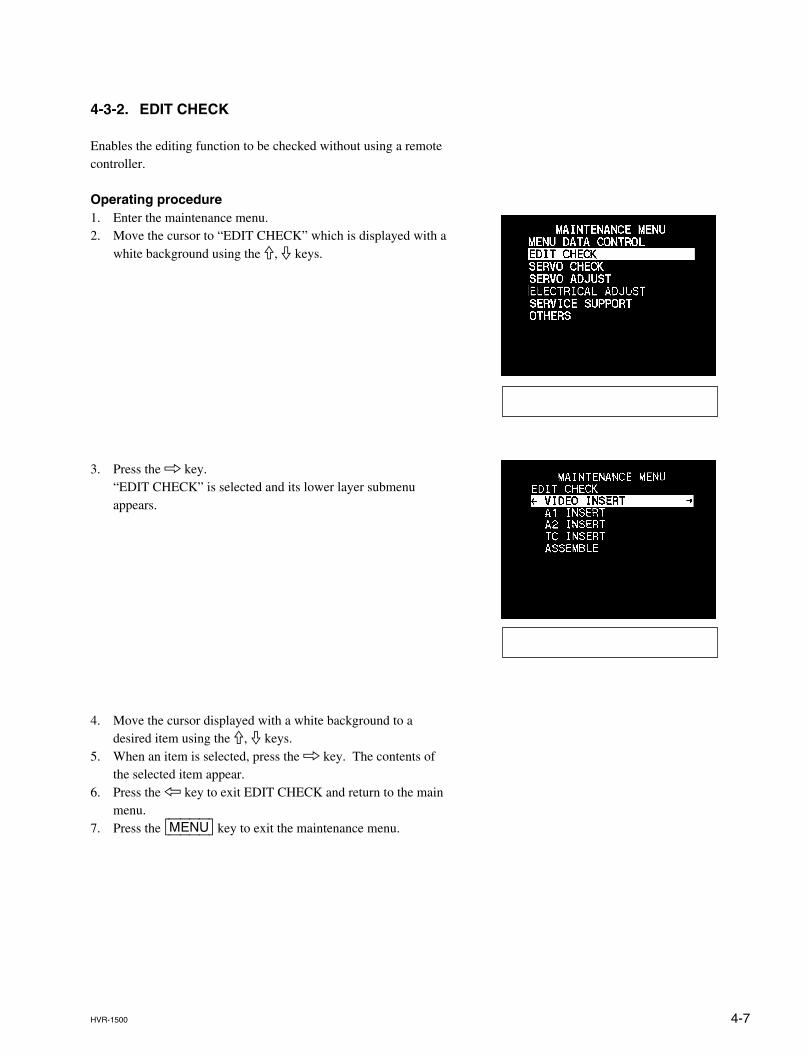
4-7HVR-1500
4-3-2. EDIT CHECK
Enables the editing function to be checked without using a remotecontroller.
Operating procedure1. Enter the maintenance menu.2. Move the cursor to “EDIT CHECK” which is displayed with a
white background using the 9, 0 keys.
3. Press the 8 key.“EDIT CHECK” is selected and its lower layer submenuappears.
4. Move the cursor displayed with a white background to adesired item using the 9, 0 keys.
5. When an item is selected, press the 8 key. The contents ofthe selected item appear.
6. Press the 7 key to exit EDIT CHECK and return to the mainmenu.
7. Press the [MENU] key to exit the maintenance menu.
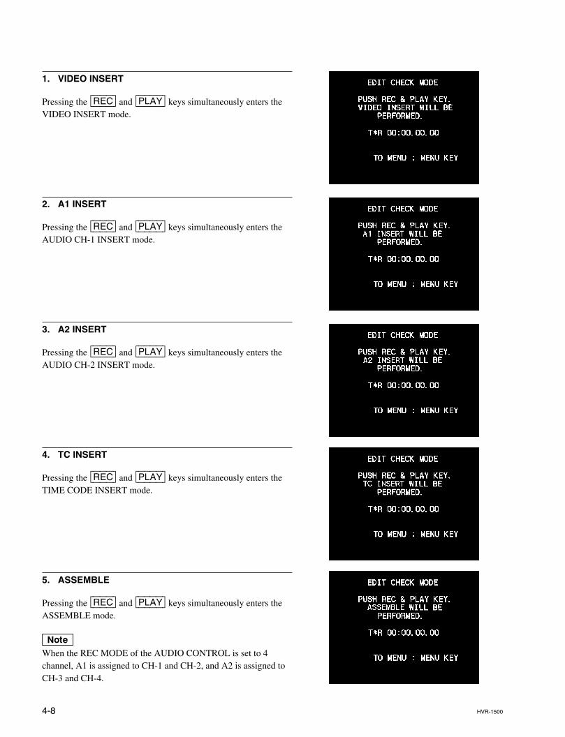
4-8 HVR-1500
1. VIDEO INSERT
Pressing the [REC] and [PLAY] keys simultaneously enters theVIDEO INSERT mode.
2. A1 INSERT
Pressing the [REC] and [PLAY] keys simultaneously enters theAUDIO CH-1 INSERT mode.
3. A2 INSERT
Pressing the [REC] and [PLAY] keys simultaneously enters theAUDIO CH-2 INSERT mode.
4. TC INSERT
Pressing the [REC] and [PLAY] keys simultaneously enters theTIME CODE INSERT mode.
5. ASSEMBLE
Pressing the [REC] and [PLAY] keys simultaneously enters theASSEMBLE mode.
nWhen the REC MODE of the AUDIO CONTROL is set to 4channel, A1 is assigned to CH-1 and CH-2, and A2 is assigned toCH-3 and CH-4.
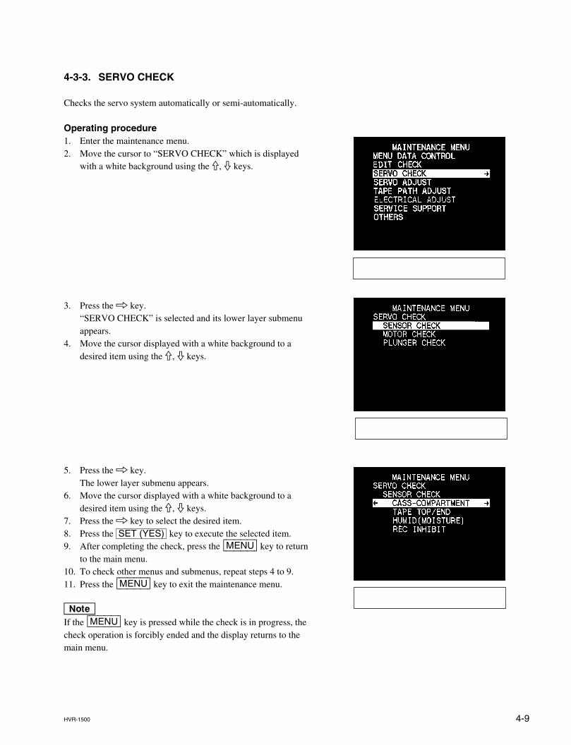
4-9HVR-1500
4-3-3. SERVO CHECK
Checks the servo system automatically or semi-automatically.
Operating procedure1. Enter the maintenance menu.2. Move the cursor to “SERVO CHECK” which is displayed
with a white background using the 9, 0 keys.
3. Press the 8 key.“SERVO CHECK” is selected and its lower layer submenuappears.
4. Move the cursor displayed with a white background to adesired item using the 9, 0 keys.
5. Press the 8 key.The lower layer submenu appears.
6. Move the cursor displayed with a white background to adesired item using the 9, 0 keys.
7. Press the 8 key to select the desired item.8. Press the SET (YES) key to execute the selected item.9. After completing the check, press the [MENU] key to return
to the main menu.10. To check other menus and submenus, repeat steps 4 to 9.11. Press the [MENU] key to exit the maintenance menu.
nIf the [MENU] key is pressed while the check is in progress, thecheck operation is forcibly ended and the display returns to themain menu.
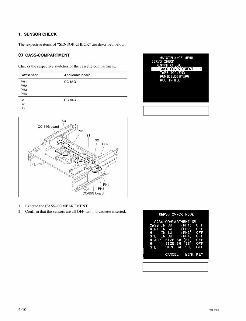
4-10 HVR-1500
1. SENSOR CHECK
The respective items of “SENSOR CHECK” are described below :
11111 CASS-COMPARTMENT
Checks the respective switches of the cassette compartment.
SW/Sensor Applicable board
PH1 CC-85GPH2PH3PH4
S1 CC-84GS2S3
1. Execute the CASS-COMPARTMENT.2. Confirm that the sensors are all OFF with no cassette inserted.
PH1S1
S3
CC-84G board
CC-85G board
S2PH2
PH4PH3
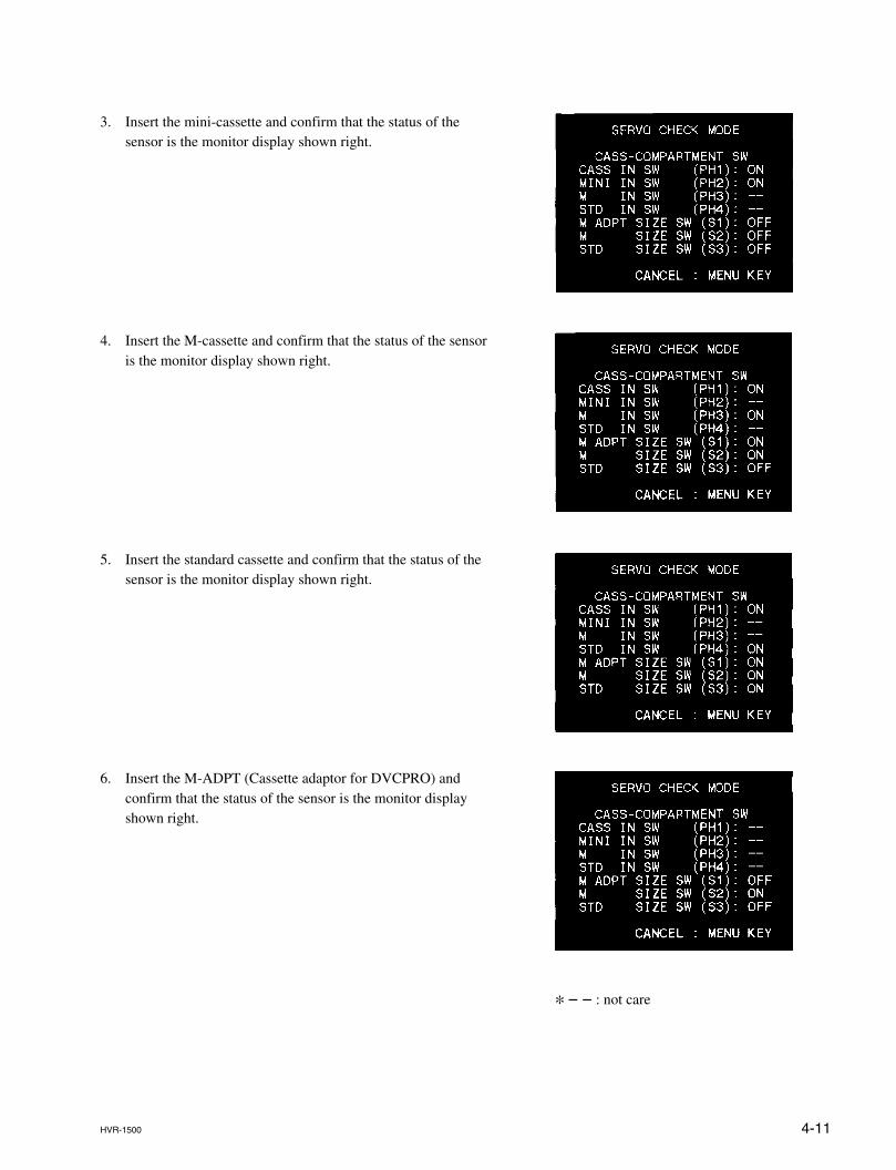
4-11HVR-1500
3. Insert the mini-cassette and confirm that the status of thesensor is the monitor display shown right.
4. Insert the M-cassette and confirm that the status of the sensoris the monitor display shown right.
5. Insert the standard cassette and confirm that the status of thesensor is the monitor display shown right.
6. Insert the M-ADPT (Cassette adaptor for DVCPRO) andconfirm that the status of the sensor is the monitor displayshown right.
* _ _ : not care
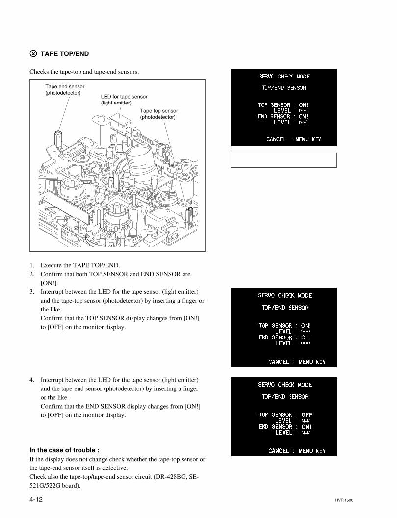
4-12 HVR-1500
22222 TAPE TOP/END
Checks the tape-top and tape-end sensors.
1. Execute the TAPE TOP/END.2. Confirm that both TOP SENSOR and END SENSOR are
[ON!].3. Interrupt between the LED for the tape sensor (light emitter)
and the tape-top sensor (photodetector) by inserting a finger orthe like.Confirm that the TOP SENSOR display changes from [ON!]to [OFF] on the monitor display.
4. Interrupt between the LED for the tape sensor (light emitter)and the tape-end sensor (photodetector) by inserting a fingeror the like.Confirm that the END SENSOR display changes from [ON!]to [OFF] on the monitor display.
In the case of trouble :If the display does not change check whether the tape-top sensor orthe tape-end sensor itself is defective.Check also the tape-top/tape-end sensor circuit (DR-428BG, SE-521G/522G board).
Tape top sensor(photodetector)
Tape end sensor(photodetector)
LED for tape sensor(light emitter)
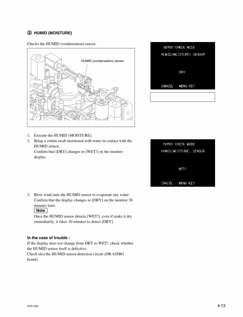
4-13HVR-1500
33333 HUMID (MOISTURE)
Checks the HUMID (condensation) sensor.
1. Execute the HUMID (MOISTURE).2. Bring a cotton swab moistened with water in contact with the
HUMID sensor.Confirm that [DRY] changes to [WET!] on the monitordisplay.
3. Blow wind onto the HUMID sensor to evaporate any water.Confirm that the display changes to [DRY] on the monitor 30minutes later.nOnce the HUMID sensor detects [WET!], even if make it dryimmediately, it takes 30 minutes to detect [DRY].
In the case of trouble :If the display does not change from DRY to WET!, check whetherthe HUMID sensor itself is defective.Check also the HUMID sensor detection circuit (DR-428BGboard).
HUMID (condensation) sensor
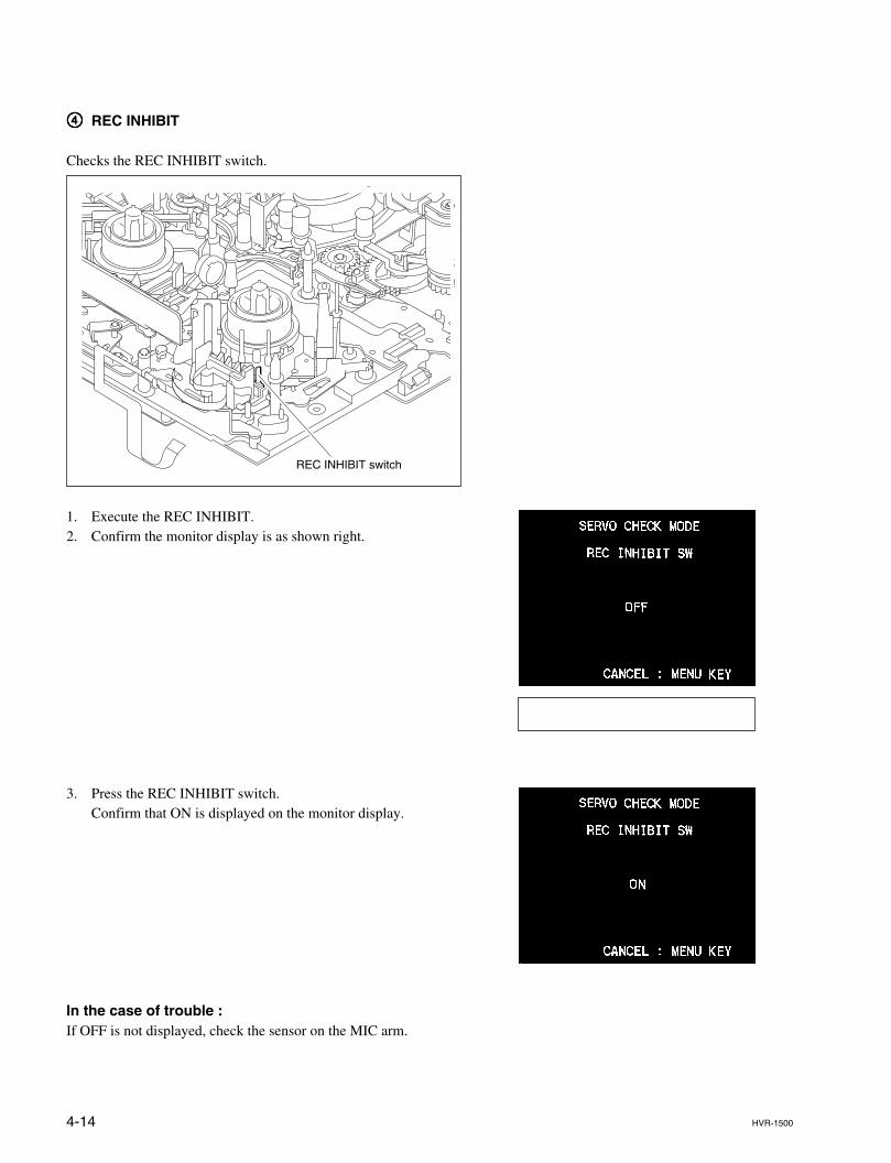
4-14 HVR-1500
44444 REC INHIBIT
Checks the REC INHIBIT switch.
1. Execute the REC INHIBIT.2. Confirm the monitor display is as shown right.
3. Press the REC INHIBIT switch.Confirm that ON is displayed on the monitor display.
In the case of trouble :If OFF is not displayed, check the sensor on the MIC arm.
REC INHIBIT switch
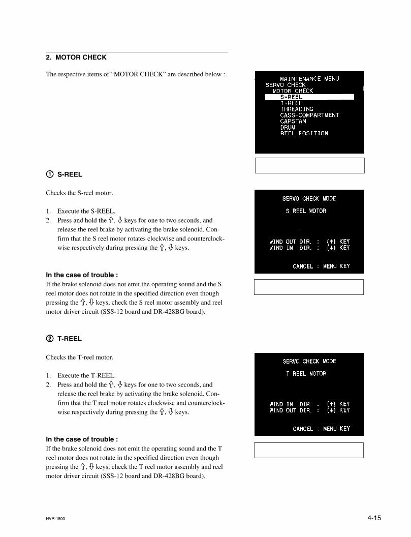
4-15HVR-1500
2. MOTOR CHECK
The respective items of “MOTOR CHECK” are described below :
11111 S-REEL
Checks the S-reel motor.
1. Execute the S-REEL.2. Press and hold the 9, 0 keys for one to two seconds, and
release the reel brake by activating the brake solenoid. Con-firm that the S reel motor rotates clockwise and counterclock-wise respectively during pressing the 9, 0 keys.
In the case of trouble :If the brake solenoid does not emit the operating sound and the Sreel motor does not rotate in the specified direction even thoughpressing the 9, 0 keys, check the S reel motor assembly and reelmotor driver circuit (SSS-12 board and DR-428BG board).
22222 T-REEL
Checks the T-reel motor.
1. Execute the T-REEL.2. Press and hold the 9, 0 keys for one to two seconds, and
release the reel brake by activating the brake solenoid. Con-firm that the T reel motor rotates clockwise and counterclock-wise respectively during pressing the 9, 0 keys.
In the case of trouble :If the brake solenoid does not emit the operating sound and the Treel motor does not rotate in the specified direction even thoughpressing the 9, 0 keys, check the T reel motor assembly and reelmotor driver circuit (SSS-12 board and DR-428BG board).
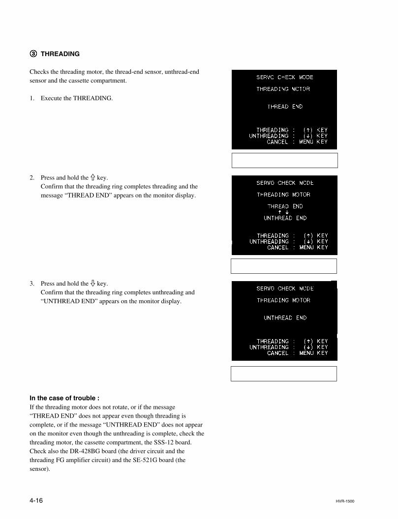
4-16 HVR-1500
33333 THREADING
Checks the threading motor, the thread-end sensor, unthread-endsensor and the cassette compartment.
1. Execute the THREADING.
2. Press and hold the 9 key.Confirm that the threading ring completes threading and themessage “THREAD END” appears on the monitor display.
3. Press and hold the 0 key.Confirm that the threading ring completes unthreading and“UNTHREAD END” appears on the monitor display.
In the case of trouble :If the threading motor does not rotate, or if the message“THREAD END” does not appear even though threading iscomplete, or if the message “UNTHREAD END” does not appearon the monitor even though the unthreading is complete, check thethreading motor, the cassette compartment, the SSS-12 board.Check also the DR-428BG board (the driver circuit and thethreading FG amplifier circuit) and the SE-521G board (thesensor).
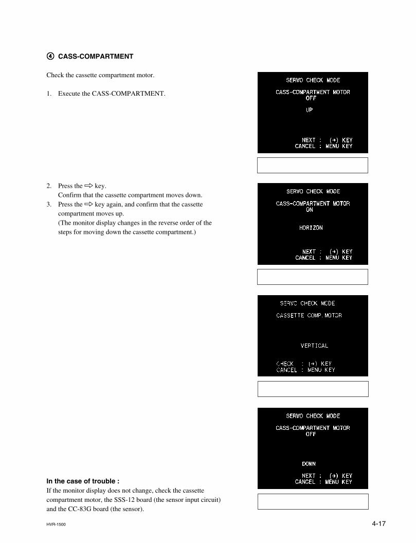
4-17HVR-1500
44444 CASS-COMPARTMENT
Check the cassette compartment motor.
1. Execute the CASS-COMPARTMENT.
2. Press the 8 key.Confirm that the cassette compartment moves down.
3. Press the 8 key again, and confirm that the cassettecompartment moves up.(The monitor display changes in the reverse order of thesteps for moving down the cassette compartment.)
In the case of trouble :If the monitor display does not change, check the cassettecompartment motor, the SSS-12 board (the sensor input circuit)and the CC-83G board (the sensor).
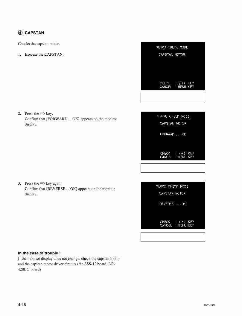
4-18 HVR-1500
55555 CAPSTAN
Checks the capstan motor.
1. Execute the CAPSTAN.
2. Press the 8 key.Confirm that [FORWARD ... OK] appears on the monitordisplay.
3. Press the 8 key again.Confirm that [REVERSE ... OK] appears on the monitordisplay.
In the case of trouble :If the monitor display does not change, check the capstan motorand the capstan motor driver circuits (the SSS-12 board, DR-428BG board)
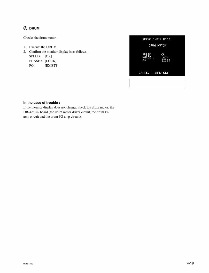
4-19HVR-1500
66666 DRUM
Checks the drum motor.
1. Execute the DRUM.2. Confirm the monitor display is as follows.
SPEED : [OK]PHASE : [LOCK]PG : [EXIST]
In the case of trouble :If the monitor display does not change, check the drum motor, theDR-428BG board (the drum motor driver circuit, the drum FGamp circuit and the drum PG amp circuit).
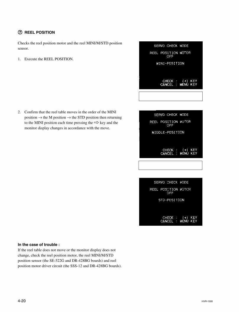
4-20 HVR-1500
77777 REEL POSITION
Checks the reel position motor and the reel MINI/M/STD positionsensor.
1. Execute the REEL POSITION.
2. Confirm that the reel table moves in the order of the MINIposition → the M position → the STD position then returningto the MINI position each time pressing the 8 key and themonitor display changes in accordance with the move.
In the case of trouble :If the reel table does not move or the monitor display does notchange, check the reel position motor, the reel MINI/M/STDposition sensor (the SE-522G and DR-428BG boards) and reelposition motor driver circuit (the SSS-12 and DR-428BG boards).
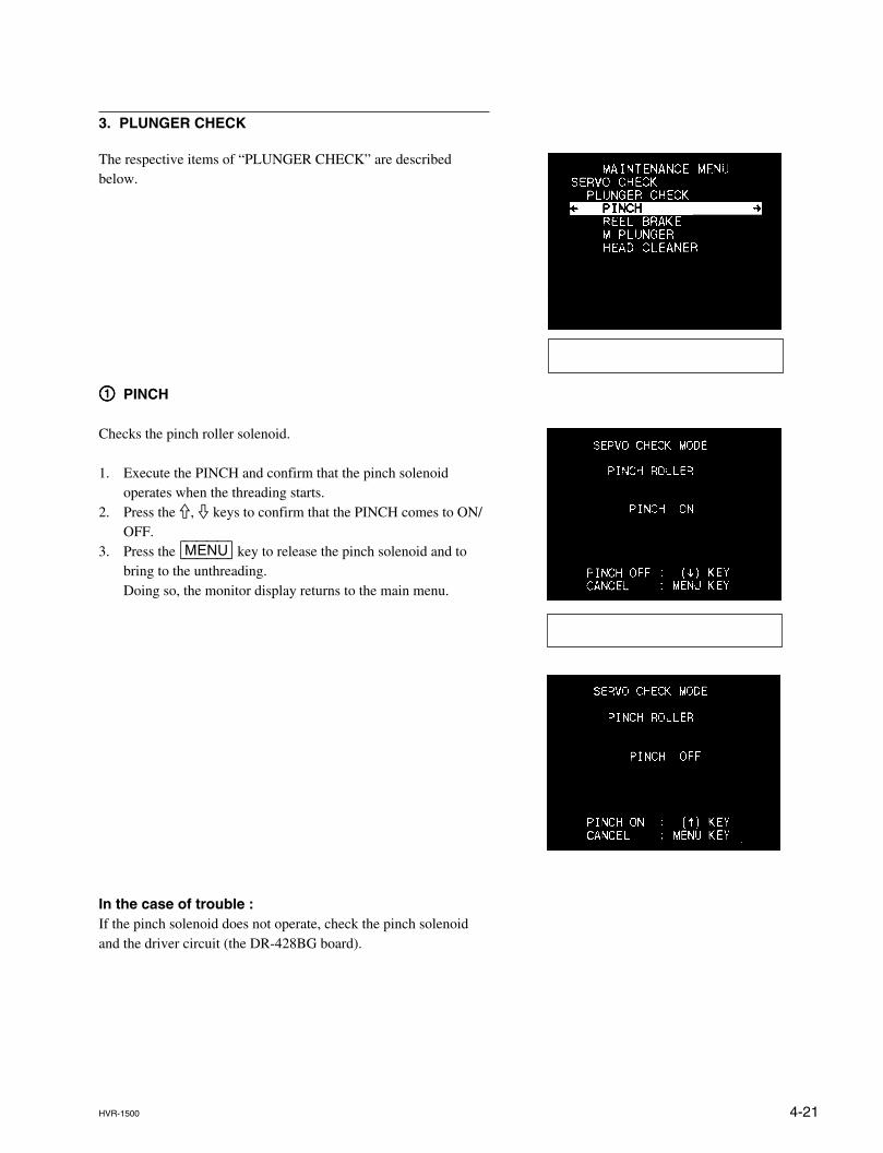
4-21HVR-1500
3. PLUNGER CHECK
The respective items of “PLUNGER CHECK” are describedbelow.
11111 PINCH
Checks the pinch roller solenoid.
1. Execute the PINCH and confirm that the pinch solenoidoperates when the threading starts.
2. Press the 9, 0 keys to confirm that the PINCH comes to ON/OFF.
3. Press the [MENU] key to release the pinch solenoid and tobring to the unthreading.Doing so, the monitor display returns to the main menu.
In the case of trouble :If the pinch solenoid does not operate, check the pinch solenoidand the driver circuit (the DR-428BG board).
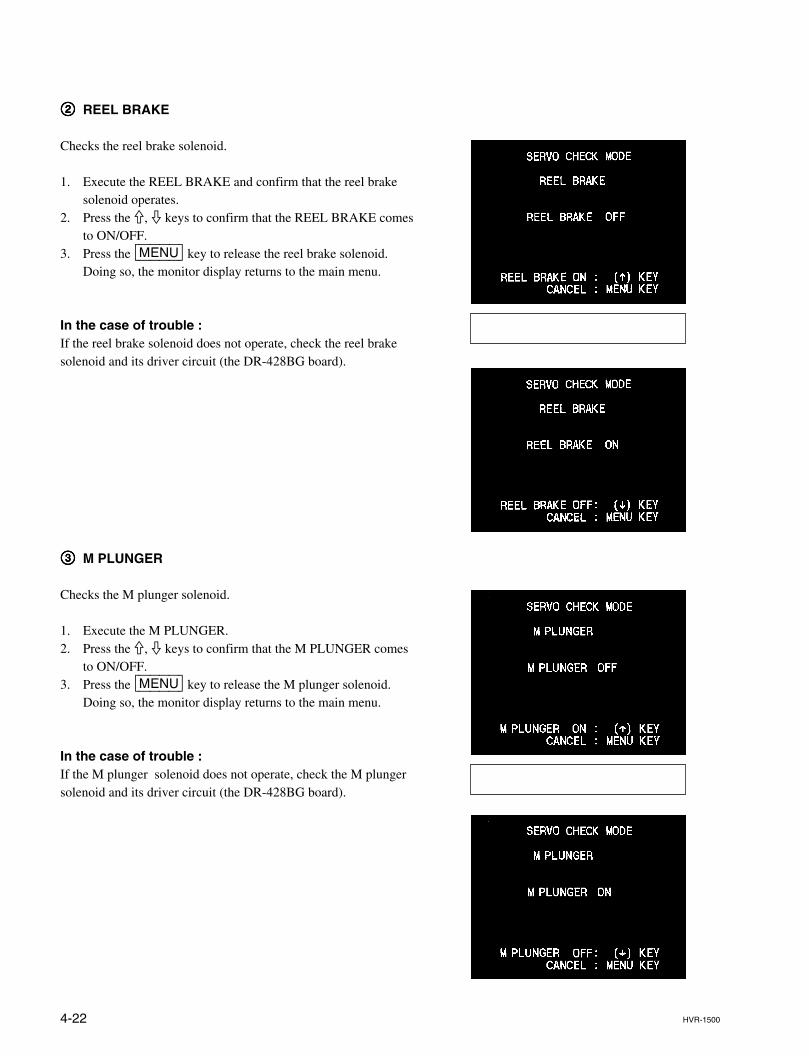
4-22 HVR-1500
22222 REEL BRAKE
Checks the reel brake solenoid.
1. Execute the REEL BRAKE and confirm that the reel brakesolenoid operates.
2. Press the 9, 0 keys to confirm that the REEL BRAKE comesto ON/OFF.
3. Press the [MENU] key to release the reel brake solenoid.Doing so, the monitor display returns to the main menu.
In the case of trouble :If the reel brake solenoid does not operate, check the reel brakesolenoid and its driver circuit (the DR-428BG board).
33333 M PLUNGER
Checks the M plunger solenoid.
1. Execute the M PLUNGER.2. Press the 9, 0 keys to confirm that the M PLUNGER comes
to ON/OFF.3. Press the [MENU] key to release the M plunger solenoid.
Doing so, the monitor display returns to the main menu.
In the case of trouble :If the M plunger solenoid does not operate, check the M plungersolenoid and its driver circuit (the DR-428BG board).
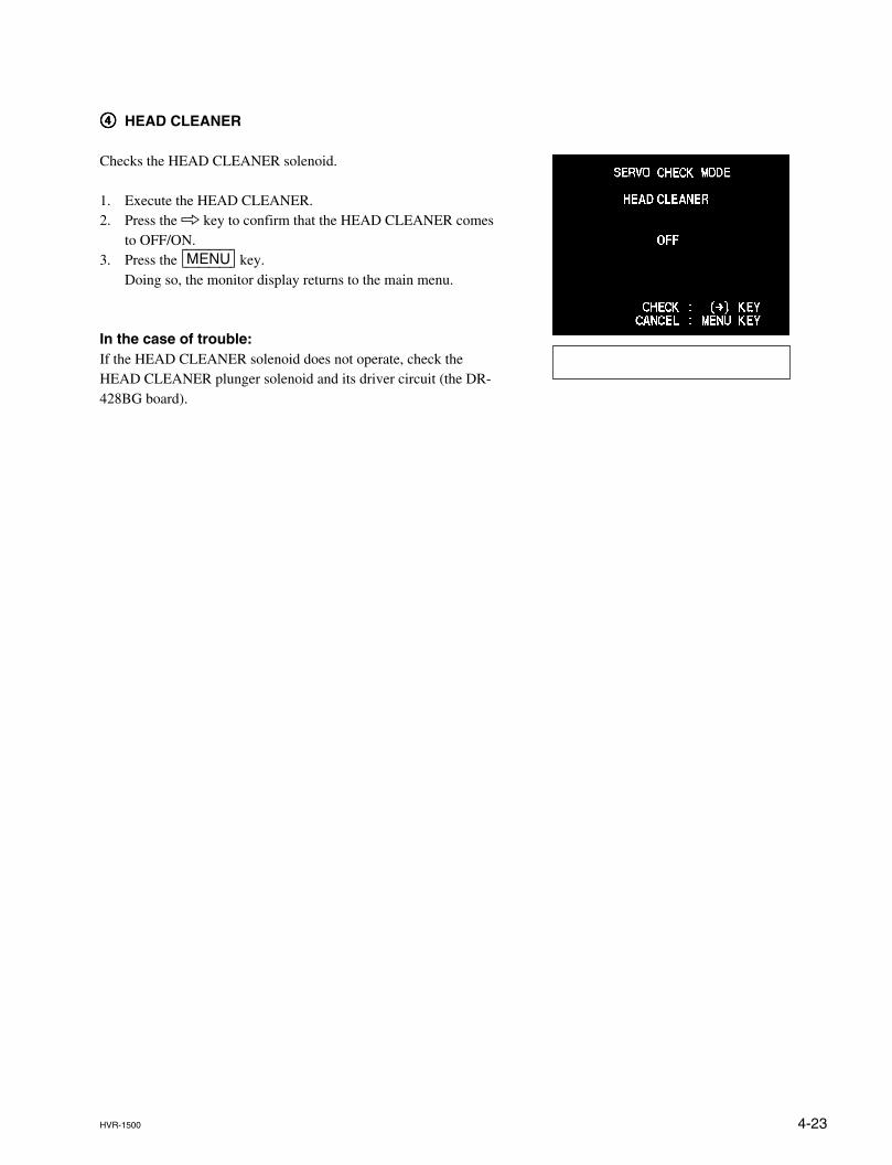
4-23HVR-1500
44444 HEAD CLEANER
Checks the HEAD CLEANER solenoid.
1. Execute the HEAD CLEANER.2. Press the 8 key to confirm that the HEAD CLEANER comes
to OFF/ON.3. Press the [MENU] key.
Doing so, the monitor display returns to the main menu.
In the case of trouble:If the HEAD CLEANER solenoid does not operate, check theHEAD CLEANER plunger solenoid and its driver circuit (the DR-428BG board).
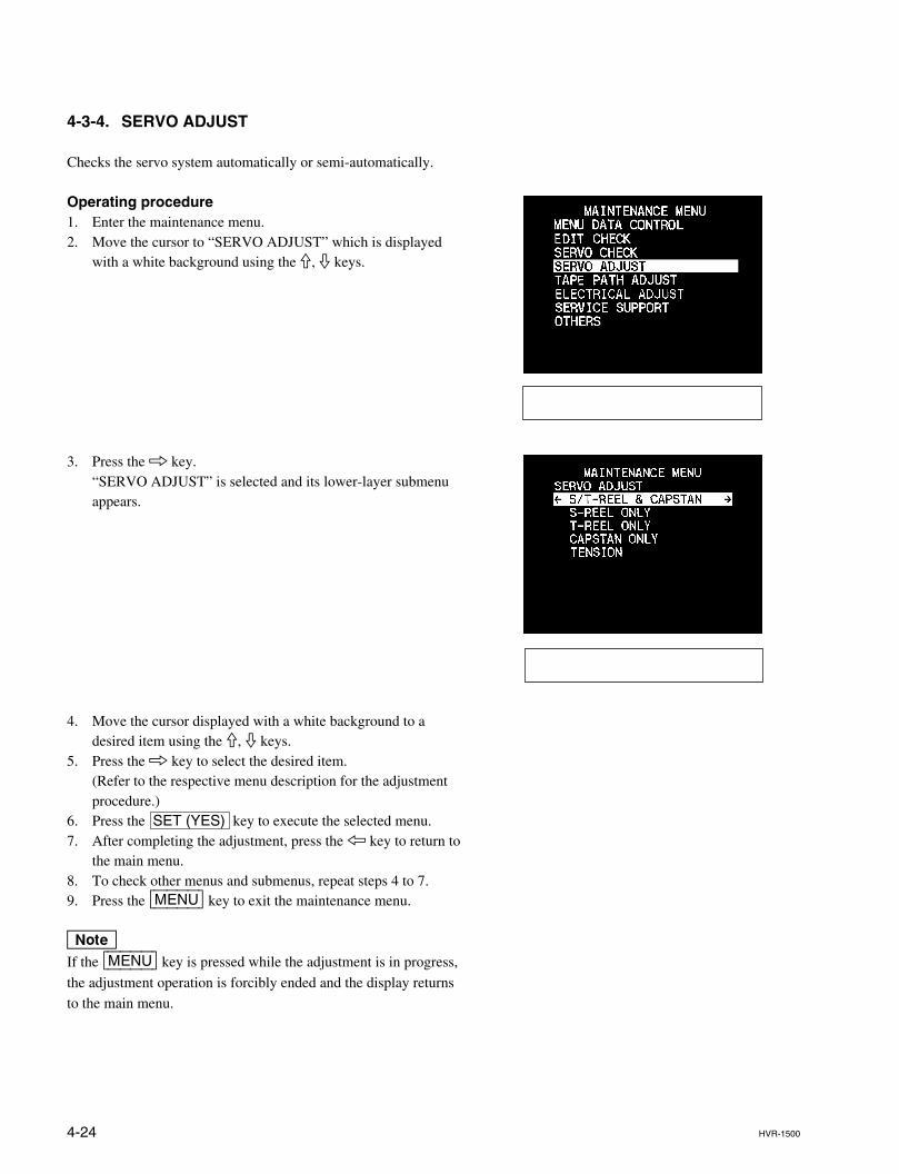
4-24 HVR-1500
4-3-4. SERVO ADJUST
Checks the servo system automatically or semi-automatically.
Operating procedure1. Enter the maintenance menu.2. Move the cursor to “SERVO ADJUST” which is displayed
with a white background using the 9, 0 keys.
3. Press the 8 key.“SERVO ADJUST” is selected and its lower-layer submenuappears.
4. Move the cursor displayed with a white background to adesired item using the 9, 0 keys.
5. Press the 8 key to select the desired item.(Refer to the respective menu description for the adjustmentprocedure.)
6. Press the SET (YES) key to execute the selected menu.7. After completing the adjustment, press the 7 key to return to
the main menu.8. To check other menus and submenus, repeat steps 4 to 7.9. Press the [MENU] key to exit the maintenance menu.
nIf the [MENU] key is pressed while the adjustment is in progress,
the adjustment operation is forcibly ended and the display returnsto the main menu.
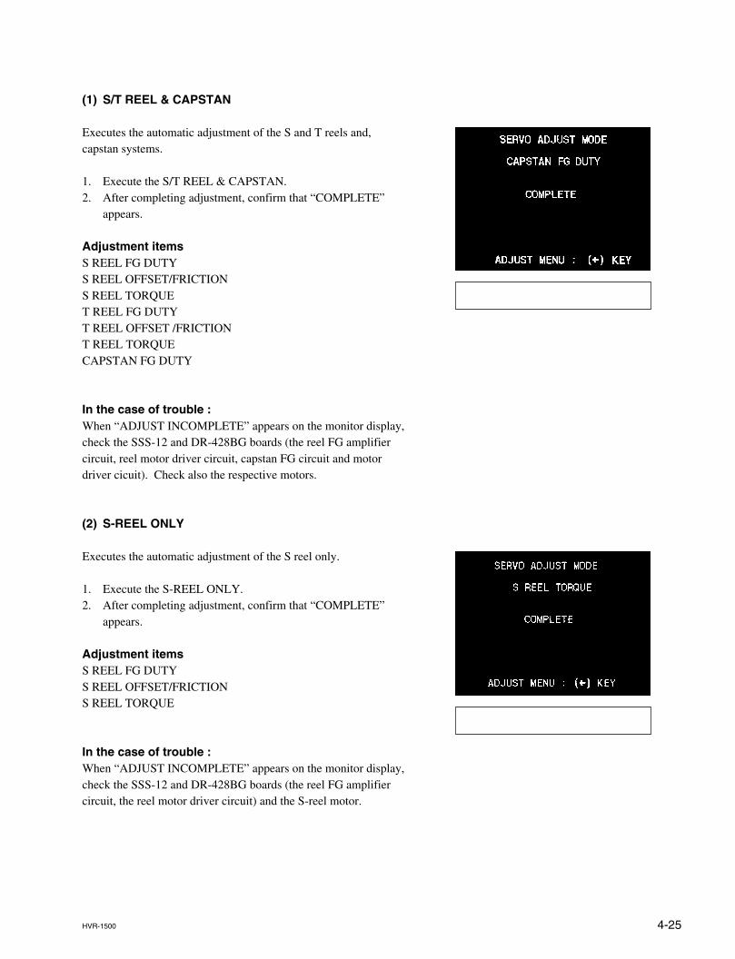
4-25HVR-1500
(1) S/T REEL & CAPSTAN
Executes the automatic adjustment of the S and T reels and,capstan systems.
1. Execute the S/T REEL & CAPSTAN.2. After completing adjustment, confirm that “COMPLETE”
appears.
Adjustment itemsS REEL FG DUTYS REEL OFFSET/FRICTIONS REEL TORQUET REEL FG DUTYT REEL OFFSET /FRICTIONT REEL TORQUECAPSTAN FG DUTY
In the case of trouble :When “ADJUST INCOMPLETE” appears on the monitor display,check the SSS-12 and DR-428BG boards (the reel FG amplifiercircuit, reel motor driver circuit, capstan FG circuit and motordriver cicuit). Check also the respective motors.
(2) S-REEL ONLY
Executes the automatic adjustment of the S reel only.
1. Execute the S-REEL ONLY.2. After completing adjustment, confirm that “COMPLETE”
appears.
Adjustment itemsS REEL FG DUTYS REEL OFFSET/FRICTIONS REEL TORQUE
In the case of trouble :When “ADJUST INCOMPLETE” appears on the monitor display,check the SSS-12 and DR-428BG boards (the reel FG amplifiercircuit, the reel motor driver circuit) and the S-reel motor.
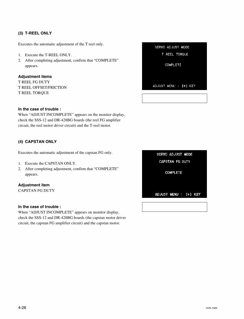
4-26 HVR-1500
(3) T-REEL ONLY
Executes the automatic adjustment of the T reel only.
1. Execute the T-REEL ONLY.2. After completing adjustment, confirm that “COMPLETE”
appears.
Adjustment itemsT REEL FG DUTYT REEL OFFSET/FRICTIONT REEL TORQUE
In the case of trouble :When “ADJUST INCOMPLETE” appears on the monitor display,check the SSS-12 and DR-428BG boards (the reel FG amplifiercircuit, the reel motor driver circuit) and the T-reel motor.
(4) CAPSTAN ONLY
Executes the automatic adjustment of the capstan FG only.
1. Execute the CAPSTAN ONLY.2. After completing adjustment, confirm that “COMPLETE”
appears.
Adjustment itemCAPSTAN FG DUTY
In the case of trouble :When “ADJUST INCOMPLETE” appears on monitor display,check the SSS-12 and DR-428BG boards (the capstan motor drivercircuit, the capstan FG amplifier circuit) and the capstan motor.
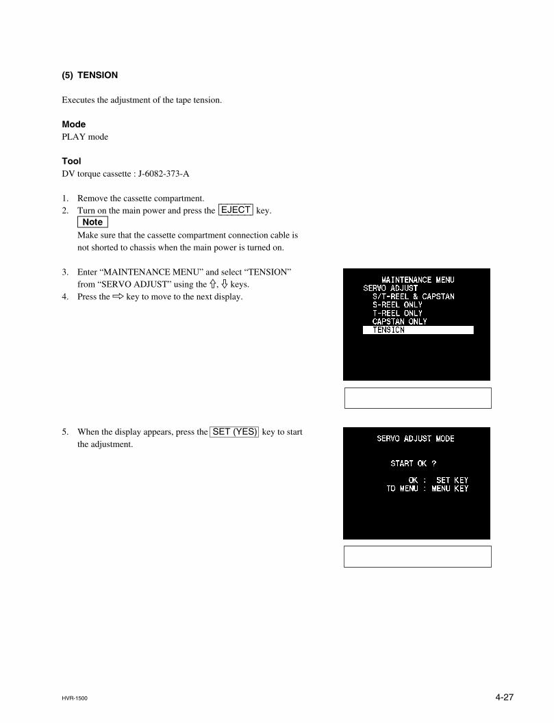
4-27HVR-1500
(5) TENSION
Executes the adjustment of the tape tension.
ModePLAY mode
ToolDV torque cassette : J-6082-373-A
1. Remove the cassette compartment.2. Turn on the main power and press the [EJECT] key.
nMake sure that the cassette compartment connection cable isnot shorted to chassis when the main power is turned on.
3. Enter “MAINTENANCE MENU” and select “TENSION”from “SERVO ADJUST” using the 9, 0 keys.
4. Press the 8 key to move to the next display.
5. When the display appears, press the SET (YES) key to startthe adjustment.
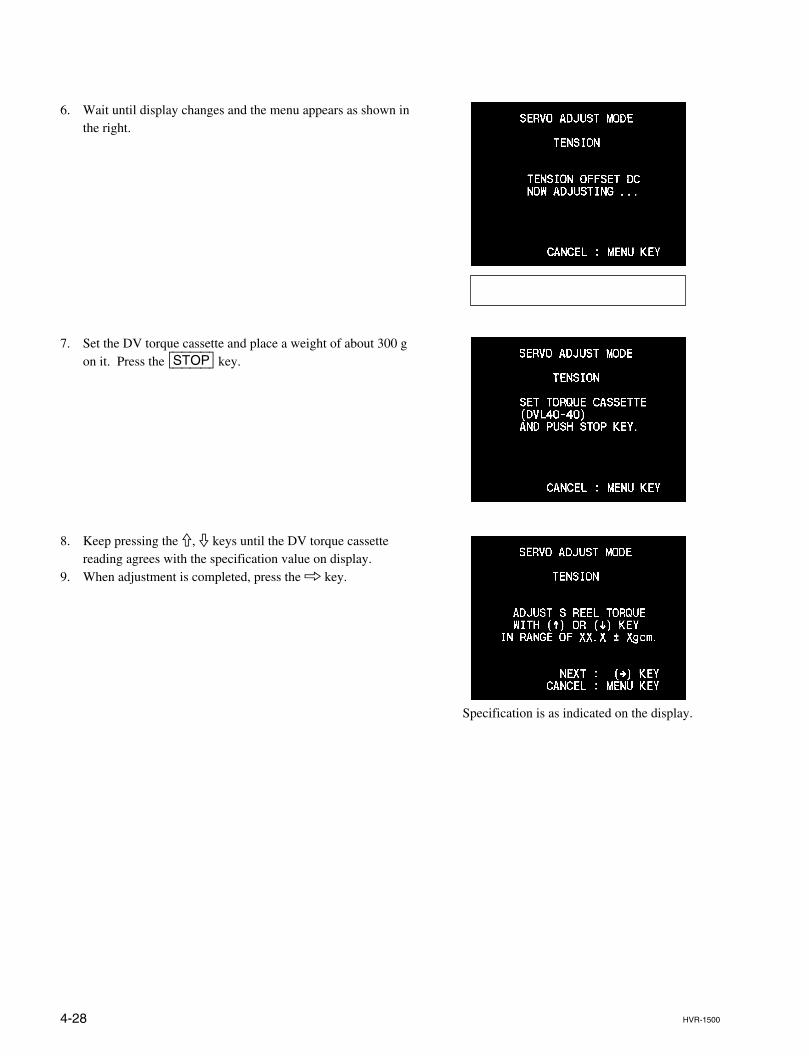
4-28 HVR-1500
Specification is as indicated on the display.
6. Wait until display changes and the menu appears as shown inthe right.
7. Set the DV torque cassette and place a weight of about 300 gon it. Press the [STOP] key.
8. Keep pressing the 9, 0 keys until the DV torque cassettereading agrees with the specification value on display.
9. When adjustment is completed, press the 8 key.
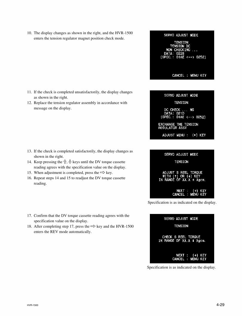
4-29HVR-1500
Specification is as indicated on the display.
Specification is as indicated on the display.
10. The display changes as shown in the right, and the HVR-1500enters the tension regulator magnet position check mode.
11. If the check is completed unsatisfactorily, the display changesas shown in the right.
12. Replace the tension regulator assembly in accordance withmessage on the display.
13. If the check is completed satisfactorily, the display changes asshown in the right.
14. Keep pressing the 9, 0 keys until the DV torque cassettereading agrees with the specification value on the display.
15. When adjustment is completed, press the 8 key.16. Repeat steps 14 and 15 to readjust the DV torque cassette
reading.
17. Confirm that the DV torque cassette reading agrees with thespecification value on the display.
18. After completing step 17, press the 8 key and the HVR-1500enters the REV mode automatically.
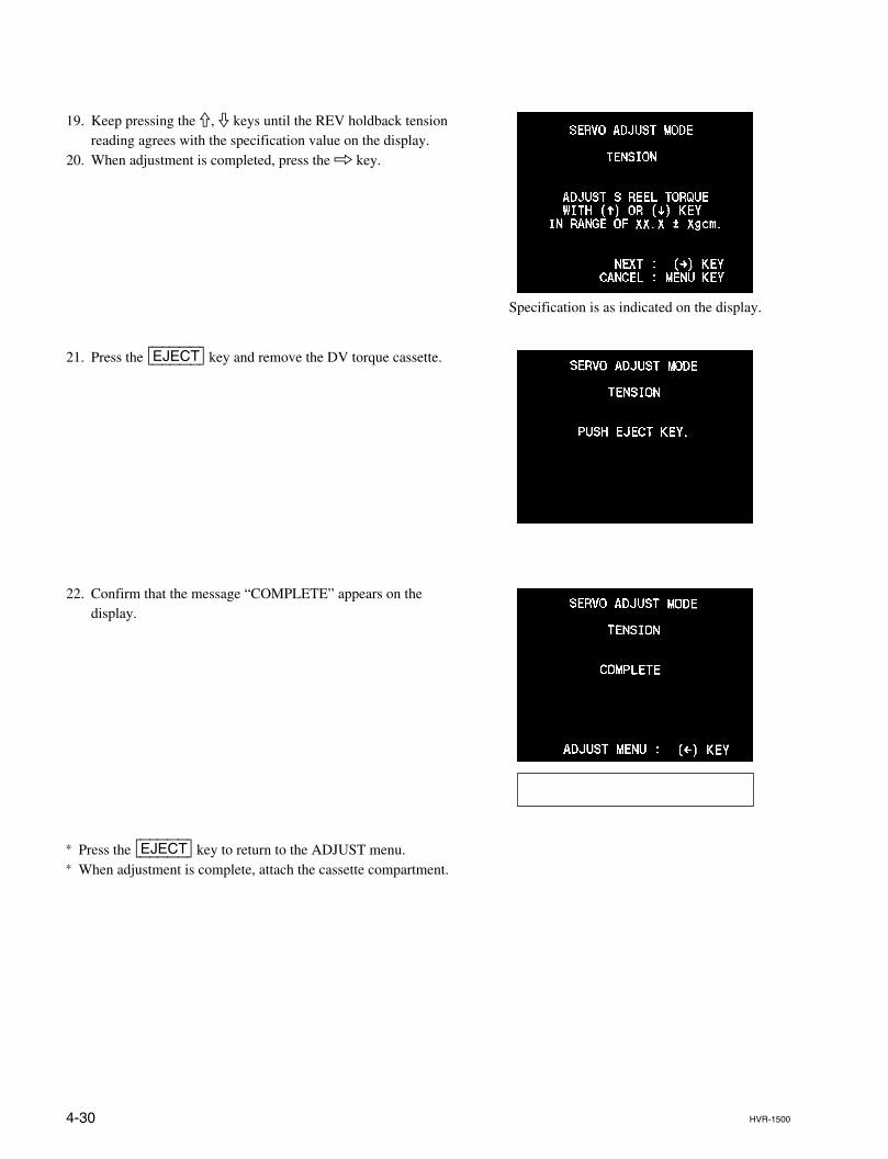
4-30 HVR-1500
Specification is as indicated on the display.
19. Keep pressing the 9, 0 keys until the REV holdback tensionreading agrees with the specification value on the display.
20. When adjustment is completed, press the 8 key.
21. Press the [EJECT] key and remove the DV torque cassette.
22. Confirm that the message “COMPLETE” appears on thedisplay.
* Press the [EJECT] key to return to the ADJUST menu.* When adjustment is complete, attach the cassette compartment.
4-31HVR-1500
4-3-5. TAPE PATH ADJUST
Executes the adjustment of the tape path.
(1) TRACKING ADJUST
For adjustment of “TRACKING ADJUST”, refer to Section 7-2.
(2) RF SWITCHING POSITION
For adjustment of “RF SWITCHING POSITION”, refer to Section7-3.
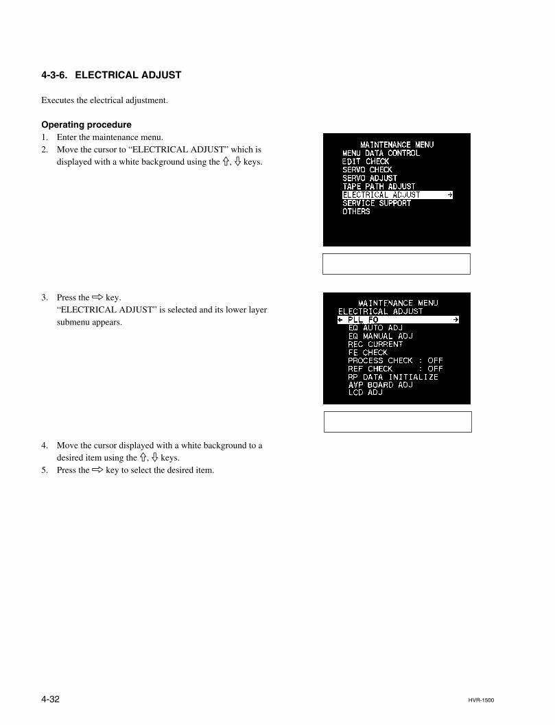
4-32 HVR-1500
4-3-6. ELECTRICAL ADJUST
Executes the electrical adjustment.
Operating procedure1. Enter the maintenance menu.2. Move the cursor to “ELECTRICAL ADJUST” which is
displayed with a white background using the 9, 0 keys.
3. Press the 8 key.“ELECTRICAL ADJUST” is selected and its lower layersubmenu appears.
4. Move the cursor displayed with a white background to adesired item using the 9, 0 keys.
5. Press the 8 key to select the desired item.
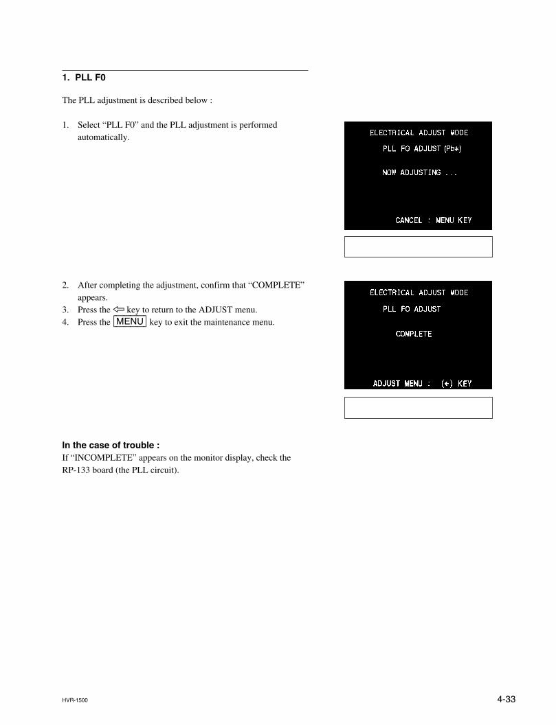
4-33HVR-1500
1. PLL F0
The PLL adjustment is described below :
1. Select “PLL F0” and the PLL adjustment is performedautomatically.
2. After completing the adjustment, confirm that “COMPLETE”appears.
3. Press the 7 key to return to the ADJUST menu.4. Press the [MENU] key to exit the maintenance menu.
In the case of trouble :If “INCOMPLETE” appears on the monitor display, check theRP-133 board (the PLL circuit).
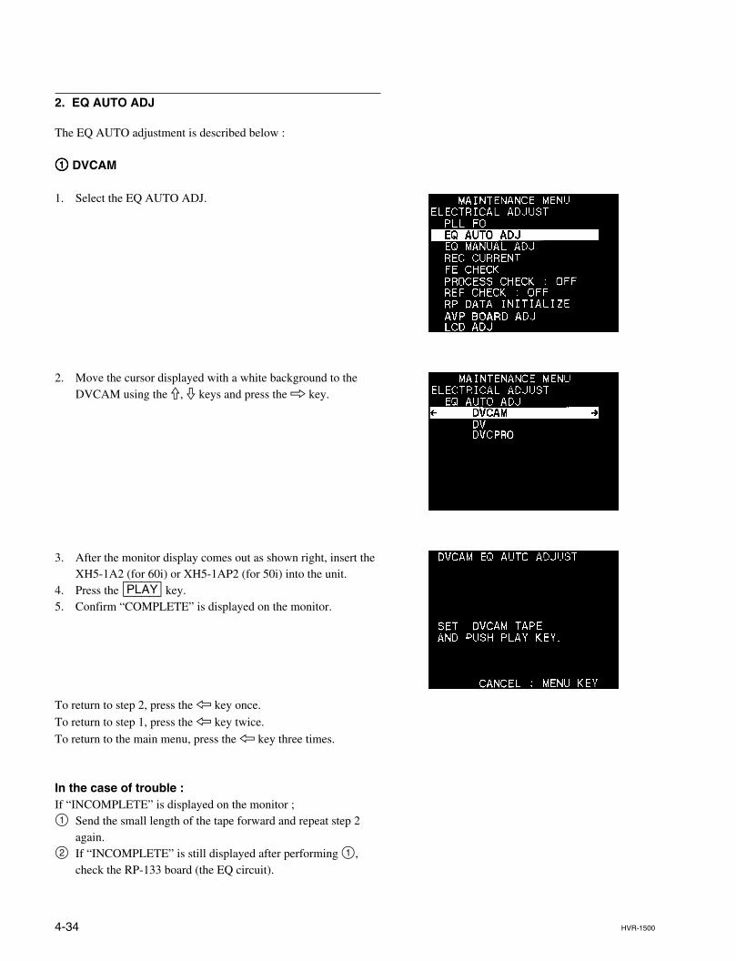
4-34 HVR-1500
2. EQ AUTO ADJ
The EQ AUTO adjustment is described below :
11111 DVCAM
1. Select the EQ AUTO ADJ.
2. Move the cursor displayed with a white background to theDVCAM using the 9, 0 keys and press the 8 key.
3. After the monitor display comes out as shown right, insert theXH5-1A2 (for 60i) or XH5-1AP2 (for 50i) into the unit.
4. Press the [PLAY] key.5. Confirm “COMPLETE” is displayed on the monitor.
To return to step 2, press the 7 key once.
To return to step 1, press the 7 key twice.
To return to the main menu, press the 7 key three times.
In the case of trouble :If “INCOMPLETE” is displayed on the monitor ;1 Send the small length of the tape forward and repeat step 2
again.2 If “INCOMPLETE” is still displayed after performing 1,
check the RP-133 board (the EQ circuit).
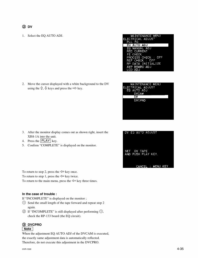
4-35HVR-1500
22222 DV
1. Select the EQ AUTO ADJ.
2. Move the cursor displayed with a white background to the DVusing the 9, 0 keys and press the 8 key.
3. After the monitor display comes out as shown right, insert theXH4-1A into the unit.
4. Press the [PLAY] key.5. Confirm “COMPLETE” is displayed on the monitor.
To return to step 2, press the 7 key once.
To return to step 1, press the 7 key twice.
To return to the main menu, press the 7 key three times.
In the case of trouble :If “INCOMPLETE” is displayed on the monitor ;1 Send the small length of the tape forward and repeat step 2
again.2 If “INCOMPLETE” is still displayed after performing 1,
check the RP-133 board (the EQ circuit).
33333 DVCPROnWhen the adjustment EQ AUTO ADJ of the DVCAM is executed,the exactly same adjustment data is automatically reflected.Therefore, do not execute this adjustment in the DVCPRO.
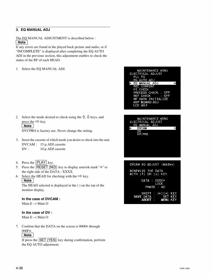
4-36 HVR-1500
3. EQ MANUAL ADJ
The EQ MANUAL ADJUSTMENT is described below :nIf any errors are found in the played back picture and audio, or if“INCOMPLETE” is displayed after completing the EQ AUTOADJ in the previous section, this adjustment enables to check thestatus of the RF of each HEAD.
1. Select the EQ MANUAL ADJ.
2. Select the mode desired to check using the 9, 0 keys, andpress the 8 key.nDVCPRO is factory use. Never change the setting.
3. Insert the cassette of which mode you desire to check into the unit.DVCAM : 15 u ADJ cassetteDV : 10 u ADJ cassette
4. Press the [PLAY] key.5. Press the RESET (NO) key to display asterisk mark “*” to
the right side of the DATA : XXXX.6. Select the HEAD for checking with the 8 key.
nThe HEAD selected is displayed in the ( ) on the top of themonitor display.
In the case of DVCAM :Main E → Main O
In the case of DV :Main E → Main O
7. Confirm that the DATA on the screen is 0000* through000F*.nIf press the SET (YES) key during confirmation, performthe EQ AUTO adjustment.
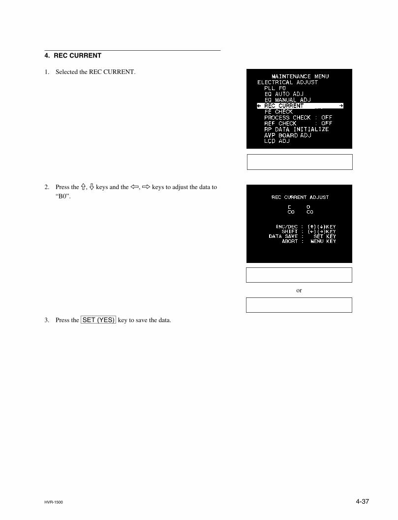
4-37HVR-1500
or
4. REC CURRENT
1. Selected the REC CURRENT.
2. Press the 9, 0 keys and the 7, 8 keys to adjust the data to
“B0”.
3. Press the SET (YES) key to save the data.
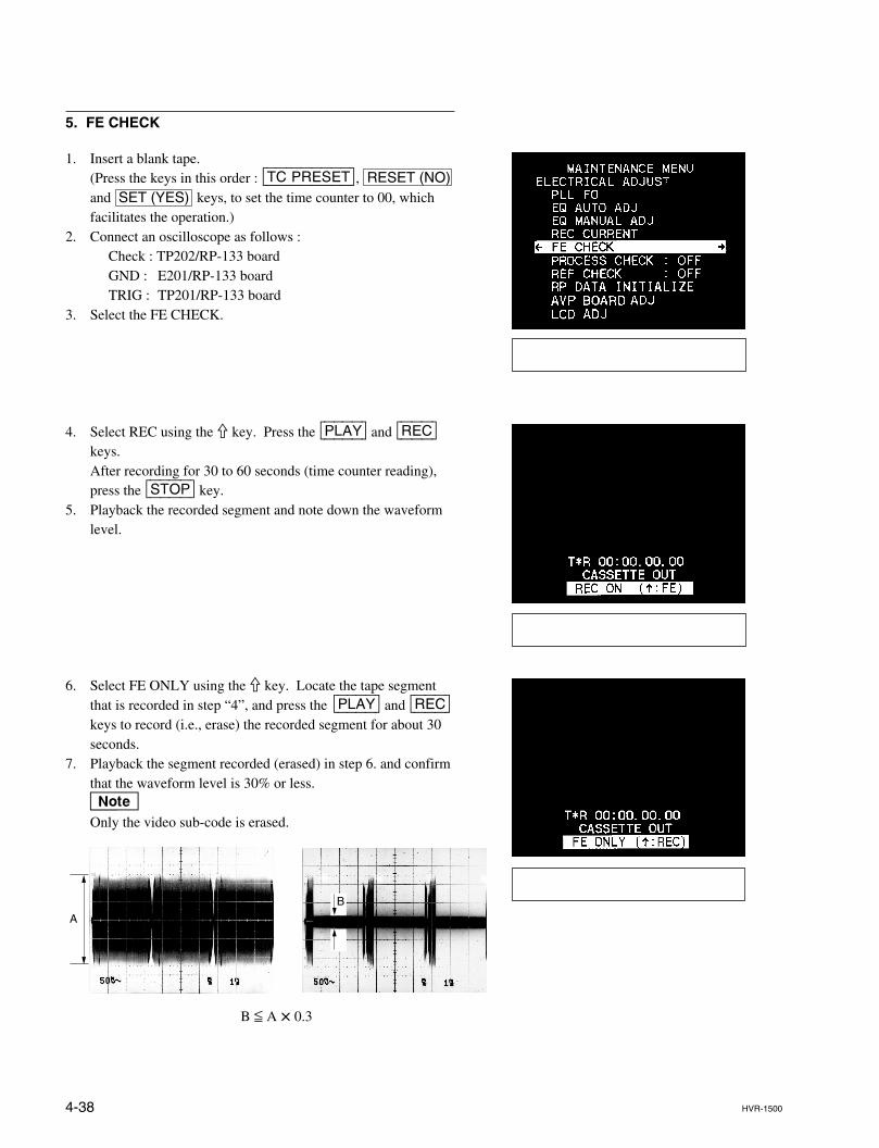
4-38 HVR-1500
5. FE CHECK
1. Insert a blank tape.(Press the keys in this order : [TC|PRESET], RESET (NO)and SET (YES) keys, to set the time counter to 00, whichfacilitates the operation.)
2. Connect an oscilloscope as follows :Check : TP202/RP-133 boardGND : E201/RP-133 boardTRIG : TP201/RP-133 board
3. Select the FE CHECK.
4. Select REC using the 9 key. Press the [PLAY] and [REC]keys.After recording for 30 to 60 seconds (time counter reading),press the [STOP] key.
5. Playback the recorded segment and note down the waveformlevel.
6. Select FE ONLY using the 9 key. Locate the tape segmentthat is recorded in step “4”, and press the [PLAY] and [REC]keys to record (i.e., erase) the recorded segment for about 30seconds.
7. Playback the segment recorded (erased) in step 6. and confirmthat the waveform level is 30% or less.nOnly the video sub-code is erased.
A
B
B < A x 0.3
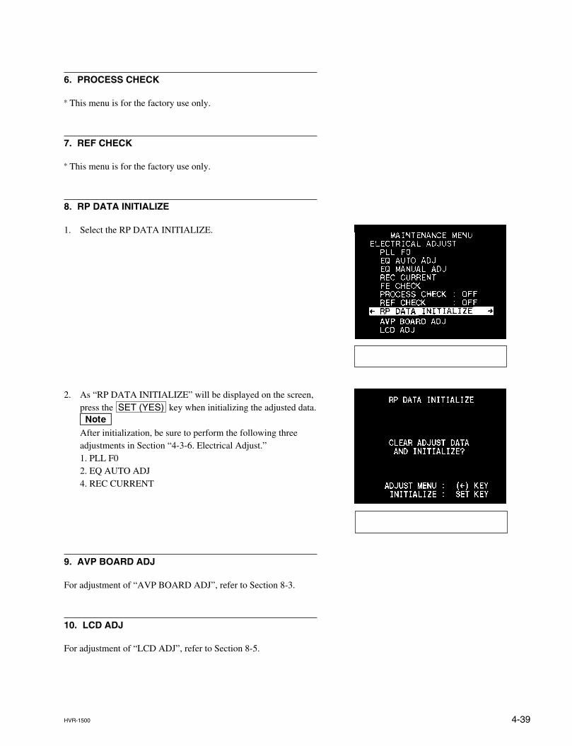
4-39HVR-1500
6. PROCESS CHECK
* This menu is for the factory use only.
7. REF CHECK
* This menu is for the factory use only.
8. RP DATA INITIALIZE
1. Select the RP DATA INITIALIZE.
2. As “RP DATA INITIALIZE” will be displayed on the screen,press the SET (YES) key when initializing the adjusted data.nAfter initialization, be sure to perform the following threeadjustments in Section “4-3-6. Electrical Adjust.”1. PLL F02. EQ AUTO ADJ4. REC CURRENT
9. AVP BOARD ADJ
For adjustment of “AVP BOARD ADJ”, refer to Section 8-3.
10. LCD ADJ
For adjustment of “LCD ADJ”, refer to Section 8-5.
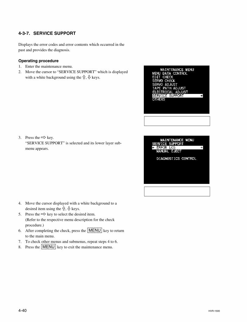
4-40 HVR-1500
4-3-7. SERVICE SUPPORT
Displays the error codes and error contents which occurred in thepast and provides the diagnosis.
Operating procedure1. Enter the maintenance menu.2. Move the cursor to “SERVICE SUPPORT” which is displayed
with a white background using the 9, 0 keys.
3. Press the 8 key.“SERVICE SUPPORT” is selected and its lower layer sub-menu appears.
4. Move the cursor displayed with a white background to adesired item using the 9, 0 keys.
5. Press the 8 key to select the desired item.(Refer to the respective menu description for the checkprocedure.)
6. After completing the check, press the [MENU] key to returnto the main menu.
7. To check other menus and submenus, repeat steps 4 to 6.8. Press the [MENU] key to exit the maintenance menu.
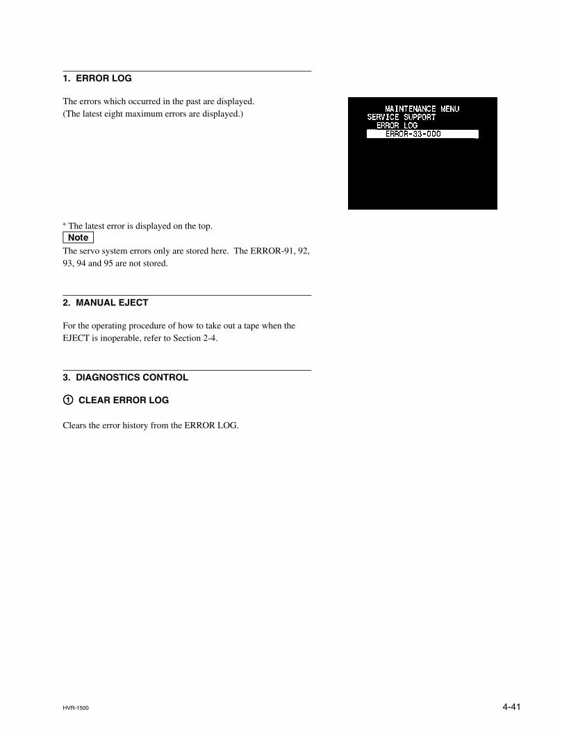
4-41HVR-1500
1. ERROR LOG
The errors which occurred in the past are displayed.(The latest eight maximum errors are displayed.)
* The latest error is displayed on the top.nThe servo system errors only are stored here. The ERROR-91, 92,93, 94 and 95 are not stored.
2. MANUAL EJECT
For the operating procedure of how to take out a tape when theEJECT is inoperable, refer to Section 2-4.
3. DIAGNOSTICS CONTROL
11111 CLEAR ERROR LOG
Clears the error history from the ERROR LOG.

4-42 HVR-1500
4-3-8. OTHERS
Enables to display the software version, check the keyboard andothers.
Operating procedure1. Enter the maintenance menu.2. Move the cursor to “OTHERS” which is displayed with a
white background using the 9, 0 keys.
3. Press the 8 key.“OTHERS” is selected and its lower layer submenu appears.
4. Move the cursor displayed with a white background to adesired item using the 9, 0 keys.
5. Press the 8 key to select the desired item.(Refer to the respective menu description for the checkprocedure after execution.)
6. After completing the check, press the [MENU] key to returnto the main menu.
7. To check other menus and submenus, repeat steps 4 to 6.8. Press the [MENU] key to exit the maintenance menu.
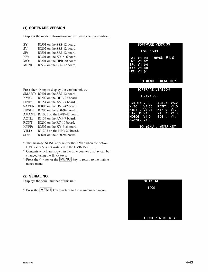
4-43HVR-1500
(1) SOFTWARE VERSION
Displays the model information and software version numbers.
SY: IC501 on the SSS-12 board.SV: IC202 on the SSS-12 board.SP: IC501 on the SSS-12 board.KY: IC301 on the KY-616 board.MO: IC201 on the HPR-20 board.MENU: IC539 on the SSS-12 board.
Press the 8 key to display the version below.SMART: IC401 on the SSS-12 board.XVIC: IC202 on the DDE-22 board.FINE: IC154 on the AVP-7 board.SAVER: IC805 on the DVP-42 board.HDSDI: IC705 on the SDI-94 board.AVANT: IC1001 on the DVP-42 board.ACTL: IC154 on the AVP-7 board.RCNT: IC200 on the RT-10 board.KYFP: IC507 on the KY-616 board.VILL: IC1203 on the HPR-20 board.SDI: IC601 on the SDI-94 board.
* The message NONE appears for the XVIC when the optionHVBK-1505 is not installed in the HVR-1500.
* Contents which are shown in the time counter display can bechanged using the 9, 0 keys.
* Press the 7 key or the [MENU] key to return to the mainte-nance menu.
(2) SERIAL NO.Displays the serial number of this unit.
* Press the [MENU] key to return to the maintenance menu.
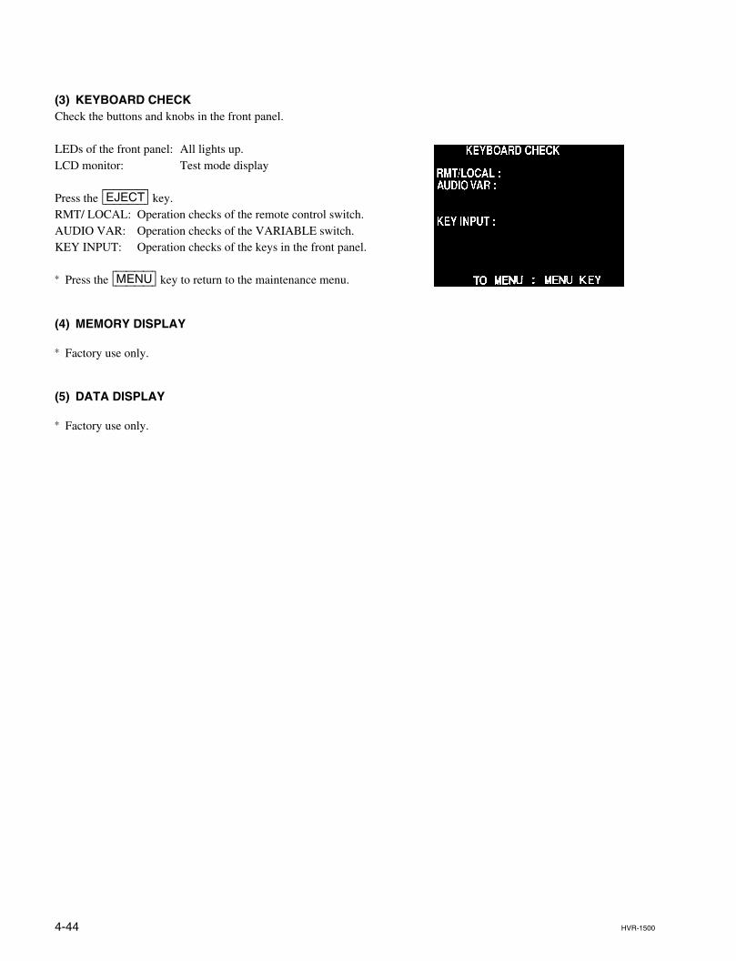
4-44 HVR-1500
(3) KEYBOARD CHECKCheck the buttons and knobs in the front panel.
LEDs of the front panel: All lights up.LCD monitor: Test mode display
Press the [EJECT] key.RMT/ LOCAL: Operation checks of the remote control switch.AUDIO VAR: Operation checks of the VARIABLE switch.KEY INPUT: Operation checks of the keys in the front panel.
* Press the [MENU] key to return to the maintenance menu.
(4) MEMORY DISPLAY
* Factory use only.
(5) DATA DISPLAY
* Factory use only.
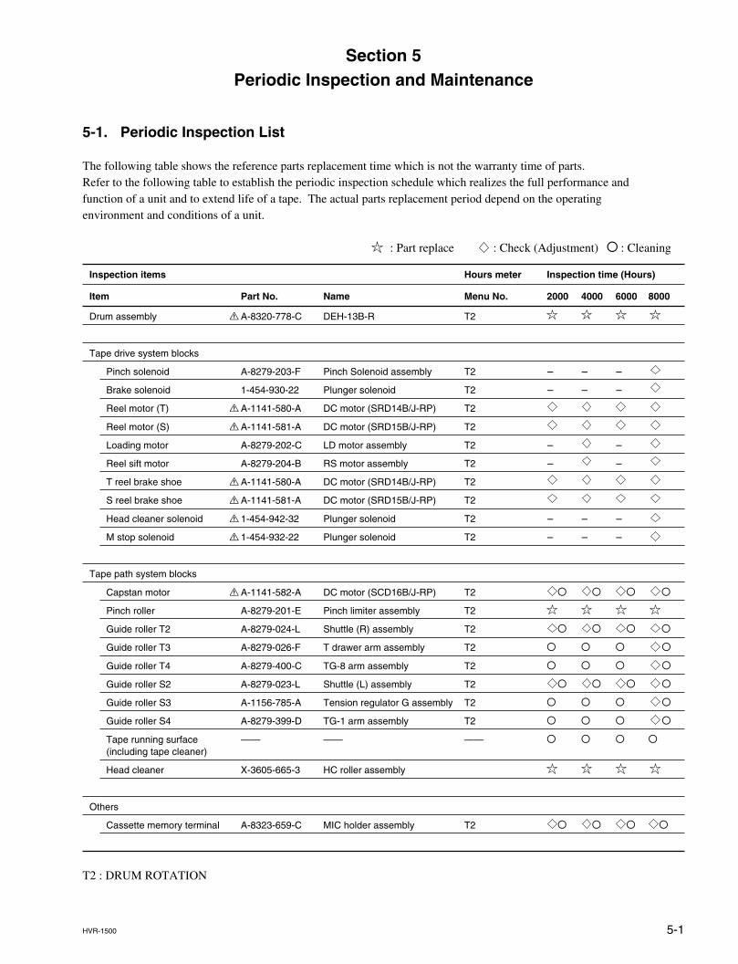
5-1HVR-1500
Section 5Periodic Inspection and Maintenance
5-1. Periodic Inspection List
The following table shows the reference parts replacement time which is not the warranty time of parts.Refer to the following table to establish the periodic inspection schedule which realizes the full performance andfunction of a unit and to extend life of a tape. The actual parts replacement period depend on the operatingenvironment and conditions of a unit.
: Part replace : Check (Adjustment) O : Cleaning
Inspection items Hours meter Inspection time (Hours)
Item Part No. Name Menu No. 2000 4000 6000 8000
Drum assembly ! A-8320-778-C DEH-13B-R T2
Tape drive system blocks
Pinch solenoid A-8279-203-F Pinch Solenoid assembly T2 _ _ _
Brake solenoid 1-454-930-22 Plunger solenoid T2 _ _ _
Reel motor (T) ! A-1141-580-A DC motor (SRD14B/J-RP) T2
Reel motor (S) ! A-1141-581-A DC motor (SRD15B/J-RP) T2
Loading motor A-8279-202-C LD motor assembly T2 _ _
Reel sift motor A-8279-204-B RS motor assembly T2 _ _
T reel brake shoe ! A-1141-580-A DC motor (SRD14B/J-RP) T2
S reel brake shoe ! A-1141-581-A DC motor (SRD15B/J-RP) T2
Head cleaner solenoid ! 1-454-942-32 Plunger solenoid T2 _ _ _
M stop solenoid ! 1-454-932-22 Plunger solenoid T2 _ _ _
Tape path system blocks
Capstan motor ! A-1141-582-A DC motor (SCD16B/J-RP) T2 O O O O
Pinch roller A-8279-201-E Pinch limiter assembly T2
Guide roller T2 A-8279-024-L Shuttle (R) assembly T2 O O O O
Guide roller T3 A-8279-026-F T drawer arm assembly T2 O O O O
Guide roller T4 A-8279-400-C TG-8 arm assembly T2 O O O O
Guide roller S2 A-8279-023-L Shuttle (L) assembly T2 O O O O
Guide roller S3 A-1156-785-A Tension regulator G assembly T2 O O O O
Guide roller S4 A-8279-399-D TG-1 arm assembly T2 O O O O
Tape running surface —— —— —— O O O O(including tape cleaner)
Head cleaner X-3605-665-3 HC roller assembly
Others
Cassette memory terminal A-8323-659-C MIC holder assembly T2 O O O O
T2 : DRUM ROTATION
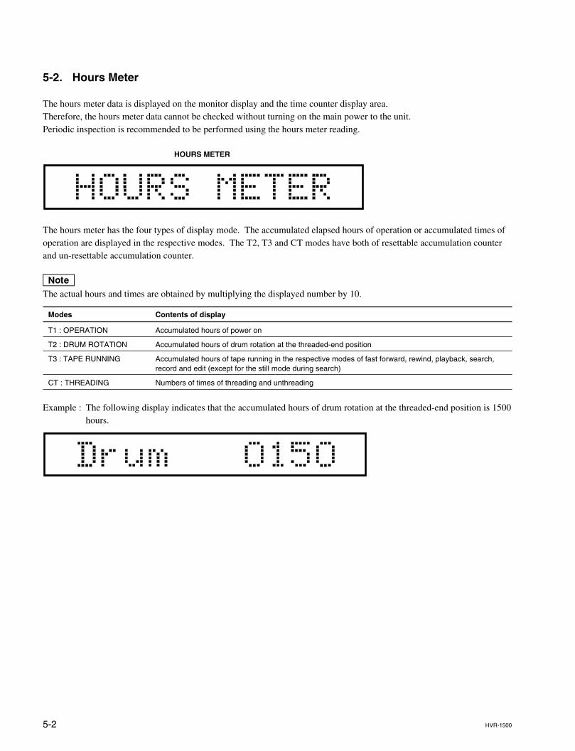
5-2 HVR-1500
5-2. Hours Meter
The hours meter data is displayed on the monitor display and the time counter display area.Therefore, the hours meter data cannot be checked without turning on the main power to the unit.Periodic inspection is recommended to be performed using the hours meter reading.
HOURS METER
The hours meter has the four types of display mode. The accumulated elapsed hours of operation or accumulated times ofoperation are displayed in the respective modes. The T2, T3 and CT modes have both of resettable accumulation counterand un-resettable accumulation counter.
nThe actual hours and times are obtained by multiplying the displayed number by 10.
Modes Contents of display
T1 : OPERATION Accumulated hours of power on
T2 : DRUM ROTATION Accumulated hours of drum rotation at the threaded-end position
T3 : TAPE RUNNING Accumulated hours of tape running in the respective modes of fast forward, rewind, playback, search,record and edit (except for the still mode during search)
CT : THREADING Numbers of times of threading and unthreading
Example : The following display indicates that the accumulated hours of drum rotation at the threaded-end position is 1500hours.
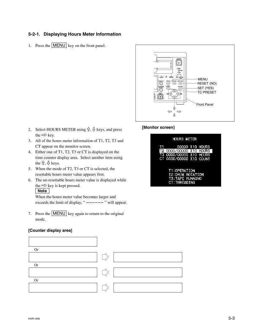
5-3HVR-1500
5-2-1. Displaying Hours Meter Information
1. Press the [MENU] key on the front panel.
2. Select HOURS METER using 9, 0 keys, and pressthe 8 key.
3. All of the hours meter information of T1, T2, T3 andCT appear on the monitor screen.
4. Either one of T1, T2, T3 or CT is displayed on thetime counter display area. Select another item usingthe 9, 0 keys.
5. When the mode of T2, T3 or CT is selected, theresettable hours meter value appears first.
6. The un-resettable hours meter value is displayed whilethe 8 key is kept pressed.nWhen the hours meter value becomes larger andexceeds the limit of display, “ ______ ” will appear.
7. Press the [MENU] key again to return to the originalmode.
[Counter display area]
[Monitor screen]
Or
Or
Or
MENURESET (NO)SET (YES)TC PRESET
Front Panel9
07 8
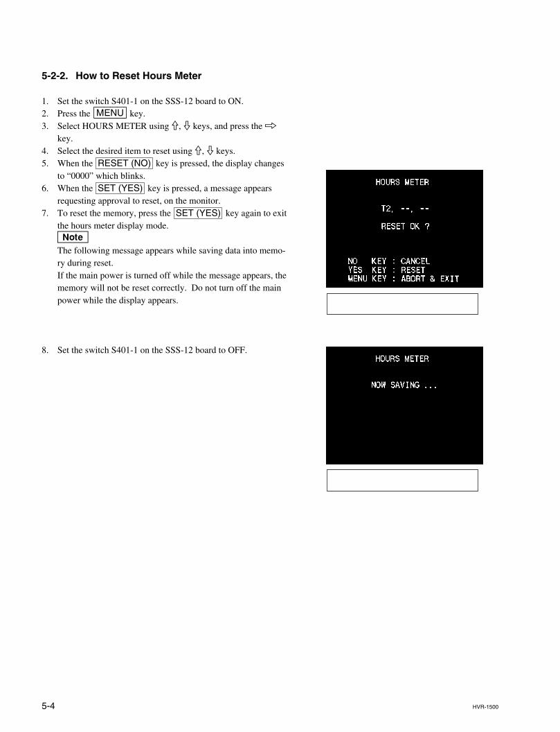
5-4 HVR-1500
5-2-2. How to Reset Hours Meter
1. Set the switch S401-1 on the SSS-12 board to ON.2. Press the [MENU] key.3. Select HOURS METER using 9, 0 keys, and press the 8
key.4. Select the desired item to reset using 9, 0 keys.5. When the RESET (NO) key is pressed, the display changes
to “0000” which blinks.6. When the SET (YES) key is pressed, a message appears
requesting approval to reset, on the monitor.7. To reset the memory, press the SET (YES) key again to exit
the hours meter display mode.nThe following message appears while saving data into memo-ry during reset.If the main power is turned off while the message appears, thememory will not be reset correctly. Do not turn off the mainpower while the display appears.
8. Set the switch S401-1 on the SSS-12 board to OFF.
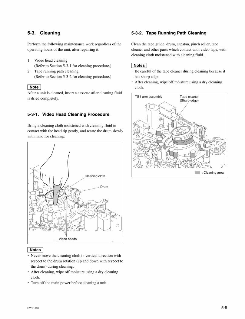
5-5HVR-1500
5-3. Cleaning
Perform the following maintenance work regardless of theoperating hours of the unit, after repairing it.
1. Video head cleaning(Refer to Section 5-3-1 for cleaning procedure.)
2. Tape running path cleaning(Refer to Section 5-3-2 for cleaning procedure.)
nAfter a unit is cleaned, insert a cassette after cleaning fluidis dried completely.
5-3-1. Video Head Cleaning Procedure
Bring a cleaning cloth moistened with cleaning fluid incontact with the head tip gently, and rotate the drum slowlywith hand for cleaning.
m. Never move the cleaning cloth in vertical direction with
respect to the drum rotation (up and down with respect tothe drum) during cleaning.
. After cleaning, wipe off moisture using a dry cleaningcloth.
. Turn off the main power before cleaning a unit.
Cleaning cloth
Drum
Video heads
5-3-2. Tape Running Path Cleaning
Clean the tape guide, drum, capstan, pinch roller, tapecleaner and other parts which contact with video tape, withcleaning cloth moistened with cleaning fluid.
m. Be careful of the tape cleaner during cleaning because it
has sharp edge.. After cleaning, wipe off moisture using a dry cleaning
cloth.
Tape cleaner(Sharp edge)
: Cleaning area
TG1 arm assembly
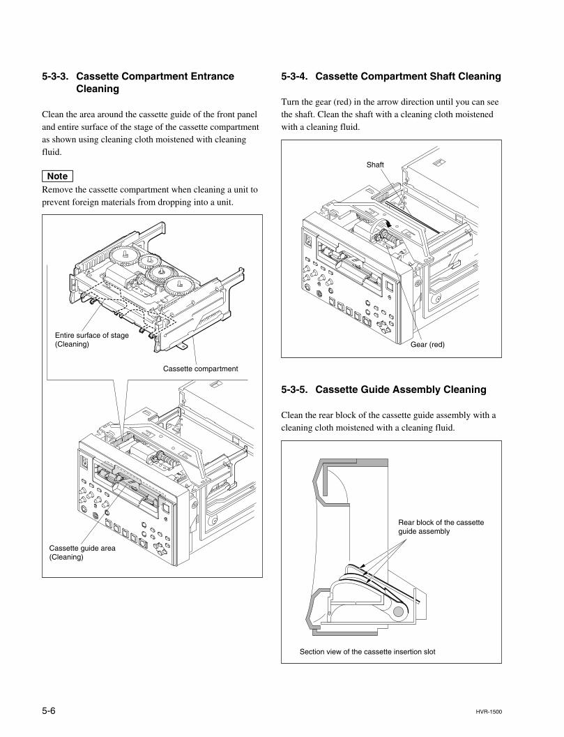
5-6 HVR-1500
5-3-3. Cassette Compartment EntranceCleaning
Clean the area around the cassette guide of the front paneland entire surface of the stage of the cassette compartmentas shown using cleaning cloth moistened with cleaningfluid.
nRemove the cassette compartment when cleaning a unit toprevent foreign materials from dropping into a unit.
5-3-4. Cassette Compartment Shaft Cleaning
Turn the gear (red) in the arrow direction until you can seethe shaft. Clean the shaft with a cleaning cloth moistenedwith a cleaning fluid.
5-3-5. Cassette Guide Assembly Cleaning
Clean the rear block of the cassette guide assembly with acleaning cloth moistened with a cleaning fluid.
Cassette guide area(Cleaning)
Entire surface of stage(Cleaning)
Cassette compartment
Gear (red)
Shaft
Rear block of the cassetteguide assembly
Section view of the cassette insertion slot
6-1HVR-1500
Section 6Replacement of Mechanical Parts
6-1. General Information on Parts Replacement and Adjustment
6-1-1. Preparation Before Starting Parts Replacement
. Remove the ornamental parts as needed.
. When replacing parts or performing mechanical adjustment, remove the cassette compartment from theHVR-1500 not so far as specified. (Refer to Section 2-8.)
. When the connector of the cassette compartment is removed, the protection circuit starts functioning.Refer to section “2-6. Operating the VTR without a Cassette Tape.” to operate the HVR-1500 withoutthe cassette compartment.
6-1-2. Drum Assembly
. The drum assembly is a periodic replacement part. The drum should be replaced in accordance with theperiodic replacement list.
. The drum assembly must be replaced in the following cases :(1) When the video heads are worn out so that the proper tape-to-head contact is lost and recording and
playback cannot be performed correctly;(2) When the rabbet guide of the lower drum is worn out so that the correct RF envelope cannot be
obtained even after adjusting the tape path to optimize the tracking.(3) When the rabbet guide or tape running surface of the lower drum is damaged;(4) If the drum rotation is abnormal and the VTR does not work properly due to noise or jitter.
6-1-3. Grease
Be sure to use only the authorized grease.If grease other than the authorized one is used, major malfunctions may result due to differences in greaseviscosity and its ingredients.If grease containing dirt is used, the shafts and bearings may be damaged and major malfunctions mayresult.
Use the following grease for the HVR-1500 :
Grease (SG941 (20 g)) : 7-662-001-39
. Do not apply grease to any parts other than the specified parts.
. Apply just enough grease to cover a coating on the surface.Wipe off any grease that oozes out into the surrounding parts with gauze or a soft cloth.
6-2 HVR-1500
6-1-4. Tightening Torque and Handling of Washers
1. Screwdrivers and Tightening Torque of ScrewsMany M1.4 and M2 screws are used in the HVR-1500.Be sure to use the authorized tools to loosen and tighten them.In addition, use a torque screwdriver to tighten the screws with the specified tightening torque.
Torque screwdriver bit (for M 1.4) : J-6325-110-ATorque screwdriver bit (for M 2) : J-6325-380-AHexagon bit (for torque screwdriver) : J-6326-120-ATorque screwdriver (for 3 kgf.cm) : J-6325-400-A
Tightening torqueFor M1.4 screw : 0.1 N.m (1.0 kgf.cm)For M2 screw : 0.2 N.m (2.0 kgf.cm)
nThe HVR-1500 uses many small screws that easily fall inside the machine when removing and re-assemblingparts. To avoid this risk, magnetize the screwdriver bit slightly enough to prevent small screws from falling intothe machine. However, when installing the drum assembly, never use a magnetized screwdriver.
2. Stop Washer and E ringDo not use old stop washers and E rings that have been removed.Always use new stop washers and E ring to attach the parts.
Stop washer (1.5) : 3-669-465-01Stop washer (2.3) : 3-669-596-01E ring (2.3) : 7-624-105-04Cotter polyethylene washer : 3-321-813-01Polyslider washer (Ø2.0) : 3-701-437-01
How to Remove the Stop Washers and E ringUse the following fixtures to remove stop washers and E ring.
Washer extracting fixture (A) :J-6082-234-Am. Be careful not to drop the stop washers and E ring inside the HVR-1500.. Be careful not to let tools touch other parts, especially the drum.
How to Attach the Stop WashersUse the following tools to attach stop washers :
Washer mounting fixture Ø1.5 : J-6082-231-AWasher mounting fixture Ø1.2 : J-6082-232-AWasher mounting fixture Ø0.8 : J-6082-233-A
(a) Insert a stop washer to the tip of the washermounting fixture.
(b) Set the thin tip of the mounting fixtureperpendicularly to the top of the shaft towhich the stop washer is to be installed.
(c) Press the thick portion of the fixture down-ward to install the stop washer onto the shaft.
Washer mounting ficture
Stop washer
Stop washer
6-3HVR-1500
6-2. Drum Replacement
Outline
ReplacementDisconnecting the connectorsRemoving the head cleaner assemblyReplacing the drum assemblyReattaching the head cleaner assemblyReconnecting the connectorsCleaning the heads and tape running surface
Adjustment after replacementTape path adjustmentRF switching position adjustmentEQ adjustment
Note
Take care not to damage the tape guides around the drum assembly, tape runningsurface on the drum, video heads of the drum assembly and so on when replacingthe drum assembly.
Basic Knowledge
Besides the periodic replacement, replace the drum assembly in the following cases.. When no proper RF waveform can be obtained even if tracking adjustment is
performed.. When the damaged tape running surface on the drum cannot be recovered.
Preparations
1. Set the unit into the unthreading end status.2. Power off the unit.3. Remove the top plate. (Refer to Section 2-7-1.)4. Remove the bottom plate. (Refer to Section 2-7-2.)5. Remove the cassette compartment assembly. (Refer to Section 2-8.)
Tool
. Cleaning cloth : 3-184-527-01
. Cleaning fluid : 9-919-573-01
. Torque screwdriver bit (for M1.4) : J-6325-110-A
. Torque screwdriver (for 3 kgf.cm) : J-6325-400-A
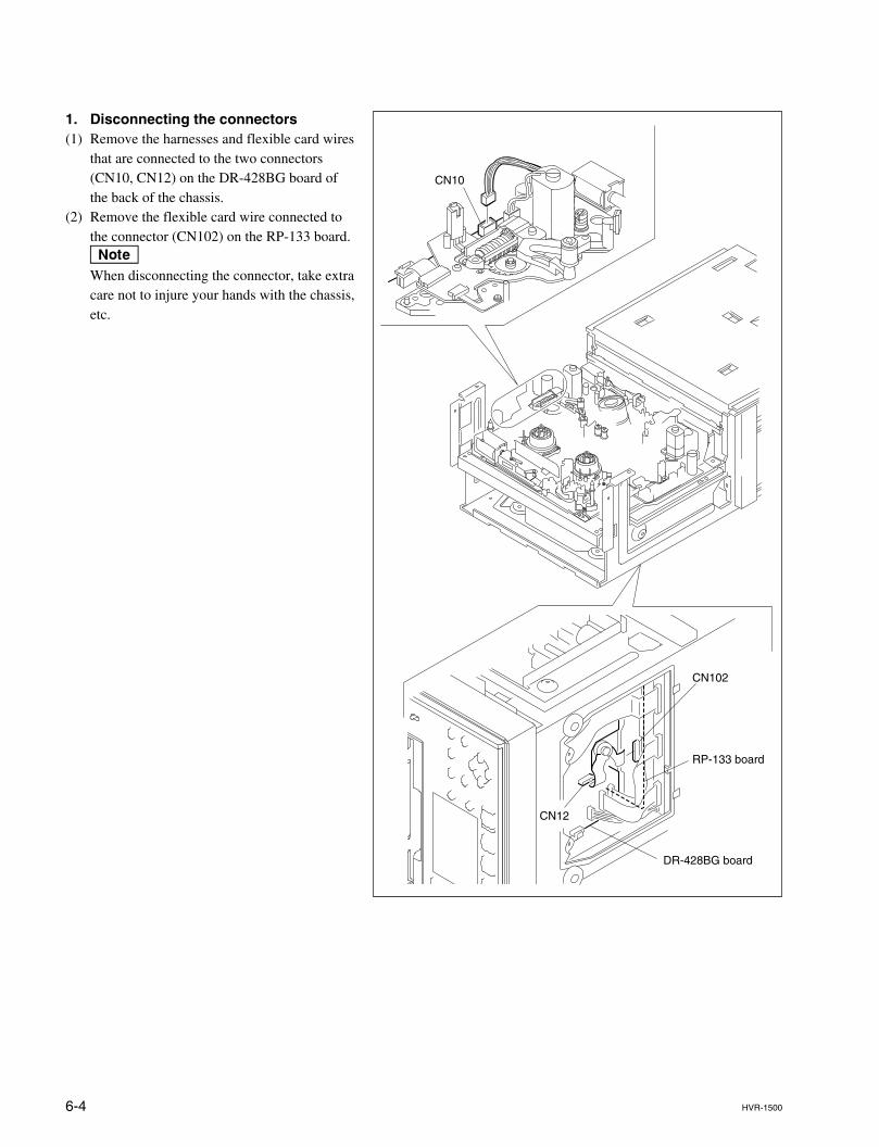
6-4 HVR-1500
CN10
CN12
CN102
RP-133 board
DR-428BG board
1. Disconnecting the connectors(1) Remove the harnesses and flexible card wires
that are connected to the two connectors(CN10, CN12) on the DR-428BG board ofthe back of the chassis.
(2) Remove the flexible card wire connected tothe connector (CN102) on the RP-133 board.nWhen disconnecting the connector, take extracare not to injure your hands with the chassis,etc.
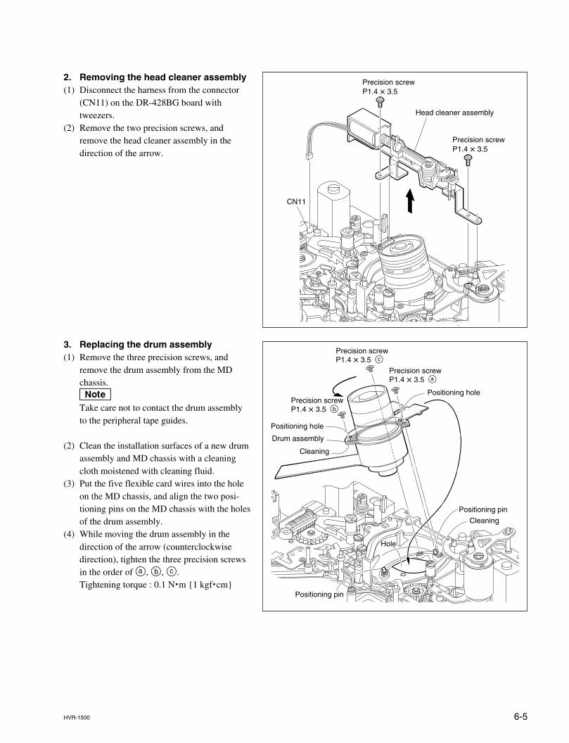
6-5HVR-1500
2. Removing the head cleaner assembly(1) Disconnect the harness from the connector
(CN11) on the DR-428BG board withtweezers.
(2) Remove the two precision screws, andremove the head cleaner assembly in thedirection of the arrow.
Precision screwP1.4 x 3.5
Head cleaner assembly
CN11
Precision screwP1.4 x 3.5
3. Replacing the drum assembly(1) Remove the three precision screws, and
remove the drum assembly from the MDchassis.nTake care not to contact the drum assemblyto the peripheral tape guides.
(2) Clean the installation surfaces of a new drumassembly and MD chassis with a cleaningcloth moistened with cleaning fluid.
(3) Put the five flexible card wires into the holeon the MD chassis, and align the two posi-tioning pins on the MD chassis with the holesof the drum assembly.
(4) While moving the drum assembly in thedirection of the arrow (counterclockwisedirection), tighten the three precision screwsin the order of a, b, c.Tightening torque : 0.1 N.m {1 kgf.cm}
Precision screwP1.4 x 3.5 c
Precision screwP1.4 x 3.5 a
Positioning hole
Positioning hole
Cleaning
Cleaning
Drum assembly
Hole
Positioning pin
Positioning pin
Precision screwP1.4 x 3.5 b
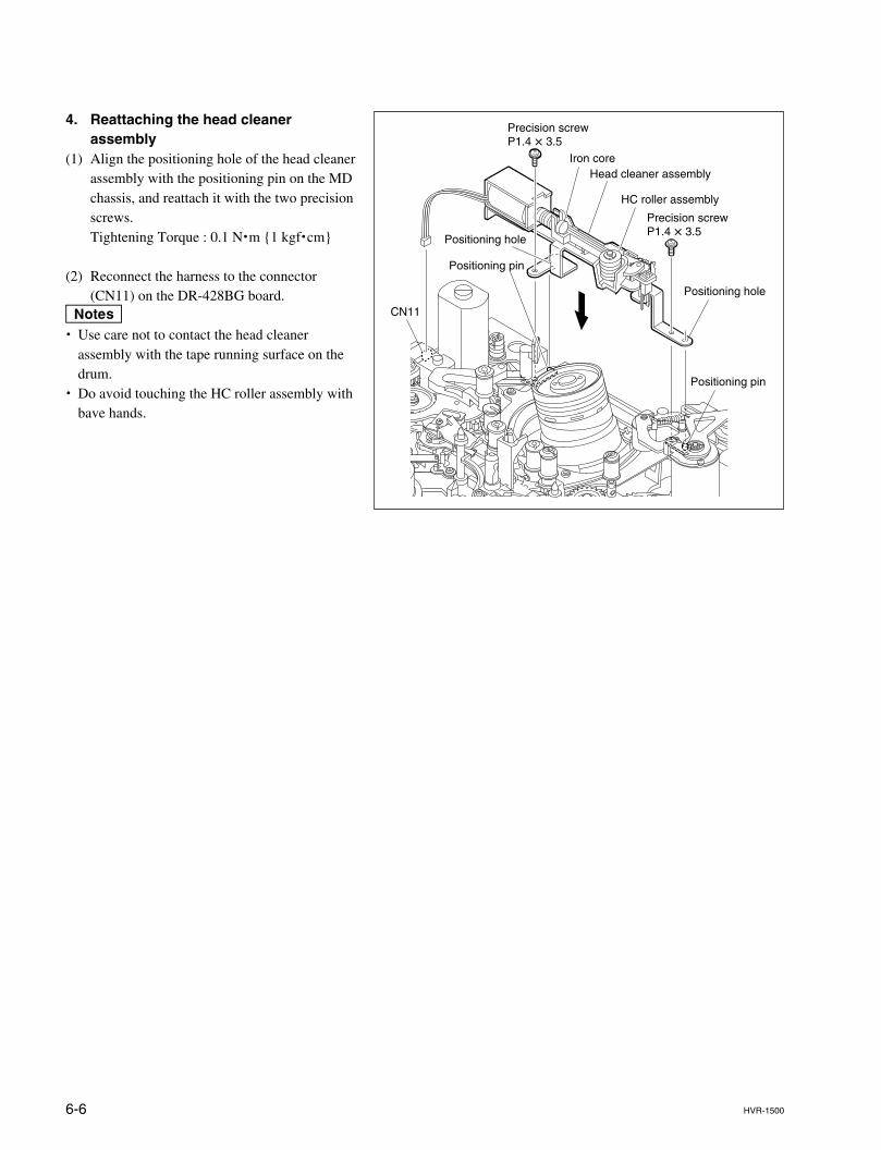
6-6 HVR-1500
4. Reattaching the head cleanerassembly
(1) Align the positioning hole of the head cleanerassembly with the positioning pin on the MDchassis, and reattach it with the two precisionscrews.Tightening Torque : 0.1 N.m {1 kgf.cm}
(2) Reconnect the harness to the connector(CN11) on the DR-428BG board.
m. Use care not to contact the head cleaner
assembly with the tape running surface on thedrum.
. Do avoid touching the HC roller assembly withbave hands.
Precision screwP1.4 x 3.5
Head cleaner assemblyIron core
CN11
Positioning hole
Positioning hole
Positioning pin
Positioning pin
Precision screwP1.4 x 3.5
HC roller assembly
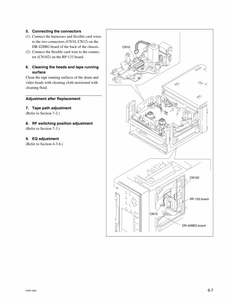
6-7HVR-1500
CN10
CN12
CN102
RP-133 board
DR-428BG board
5. Connecting the connectors(1) Connect the harnesses and flexible card wires
to the two connectors (CN10, CN12) on theDR-428BG board of the back of the chassis.
(2) Connect the flexible card wire to the connec-tor (CN102) on the RP-133 board.
6. Cleaning the heads and tape runningsurface
Clean the tape running surfaces of the drum andvideo heads with cleaning cloth moistened withcleaning fluid.
Adjustment after Replacement
7. Tape path adjustment(Refer to Section 7-2.)
8. RF switching position adjustment(Refer to Section 7-3.)
9. EQ adjustment(Refer to Section 4-3-6.)
6-8 HVR-1500
6-3. Brake Solenoid Replacement
Outline
ReplacementDisconnecting the connectorRemoving the brake assemblyReplacing the brake solenoidReattaching the brake assemblyReconnecting the connectorChecking the performance
Note
Prepare a new stop washer when replacing the brake solenoid.Stop washer (1.5) : 3-669-465-01 x 1
Preparation
1. After setting the unit to the L cassette position, set it to the unthreading endstatus.
2. Power off the unit.3. Remove the top panel. (Refer to Section 2-7-1.)4. Remove the cassette compartment. (Refer to Section 2-8.)
Tools
. Torque screwdriver’s bit (for M1.4) : J-6325-110-A
. Torque screwdriver’s bit (for M2) : J-6325-380-A
. Torque screwdriver (for 3 kgf.cm) : J-6325-400-A
. Washer extracting fixture (A) : J-6082-234-A
. Washer mounting fixture Ø1.5 : J-6082-231-A
. Tweezers
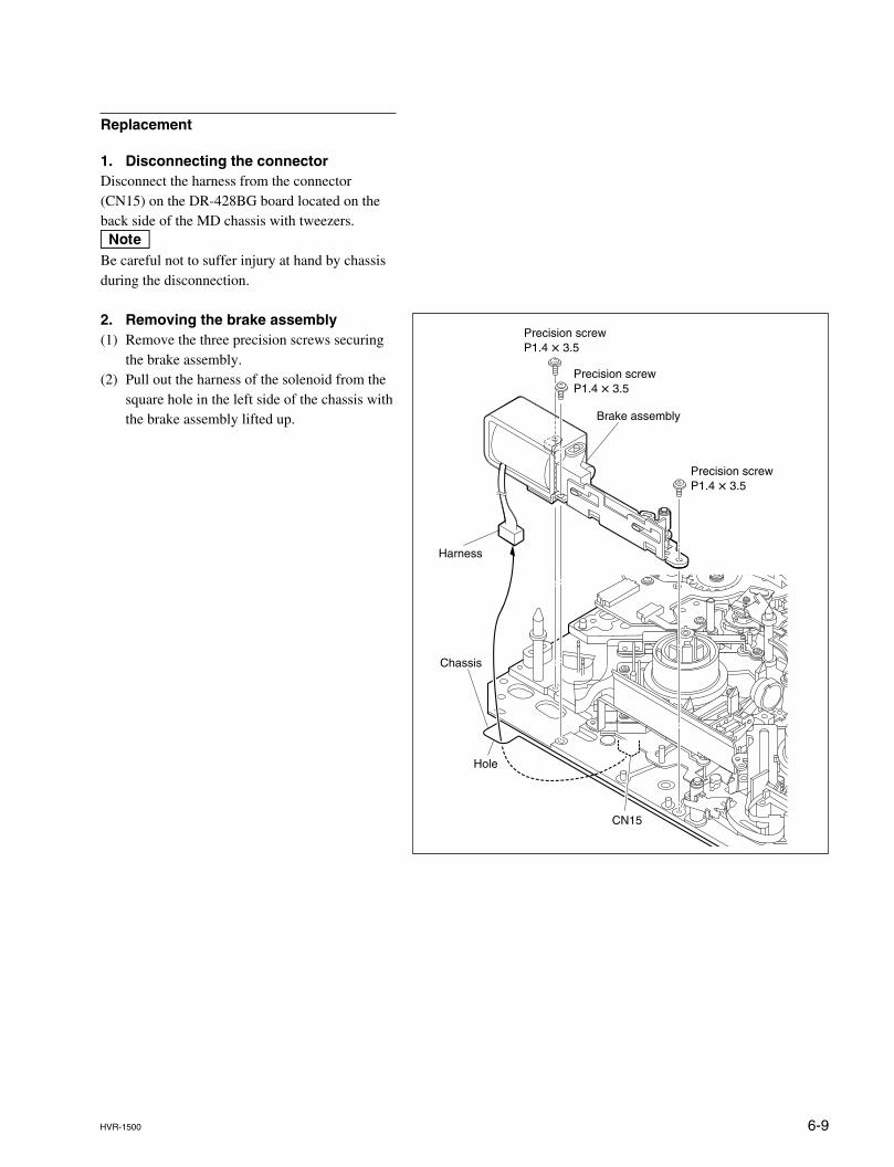
6-9HVR-1500
Replacement
1. Disconnecting the connectorDisconnect the harness from the connector(CN15) on the DR-428BG board located on theback side of the MD chassis with tweezers.nBe careful not to suffer injury at hand by chassisduring the disconnection.
2. Removing the brake assembly(1) Remove the three precision screws securing
the brake assembly.(2) Pull out the harness of the solenoid from the
square hole in the left side of the chassis withthe brake assembly lifted up.
Chassis
Harness
Precision screwP1.4 x 3.5
Precision screwP1.4 x 3.5
Precision screwP1.4 x 3.5
Brake assembly
CN15
Hole
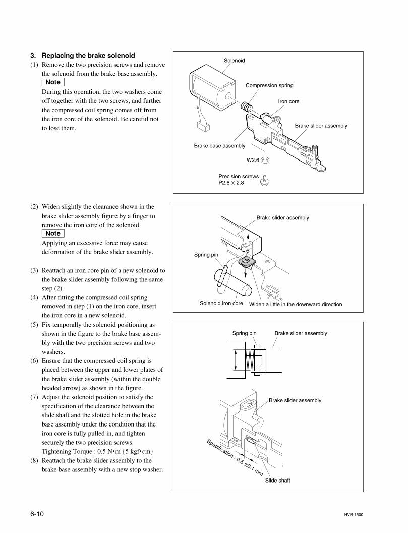
6-10 HVR-1500
Brake slider assembly
Brake slider assemblySpring pin
Slide shaft
Specification : 0.5 ±0.1 mm
3. Replacing the brake solenoid(1) Remove the two precision screws and remove
the solenoid from the brake base assembly.nDuring this operation, the two washers comeoff together with the two screws, and furtherthe compressed coil spring comes off fromthe iron core of the solenoid. Be careful notto lose them.
Solenoid
Compression spring
Iron core
Brake slider assembly
Brake base assembly
W2.6
Precision screwsP2.6 x 2.8
Brake slider assembly
Widen a little in the downward directionSolenoid iron core
Spring pin
(2) Widen slightly the clearance shown in thebrake slider assembly figure by a finger toremove the iron core of the solenoid.nApplying an excessive force may causedeformation of the brake slider assembly.
(3) Reattach an iron core pin of a new solenoid tothe brake slider assembly following the samestep (2).
(4) After fitting the compressed coil springremoved in step (1) on the iron core, insertthe iron core in a new solenoid.
(5) Fix temporally the solenoid positioning asshown in the figure to the brake base assem-bly with the two precision screws and twowashers.
(6) Ensure that the compressed coil spring isplaced between the upper and lower plates ofthe brake slider assembly (within the doubleheaded arrow) as shown in the figure.
(7) Adjust the solenoid position to satisfy thespecification of the clearance between theslide shaft and the slotted hole in the brakebase assembly under the condition that theiron core is fully pulled in, and tightensecurely the two precision screws.Tightening Torque : 0.5 N.m {5 kgf.cm}
(8) Reattach the brake slider assembly to thebrake base assembly with a new stop washer.
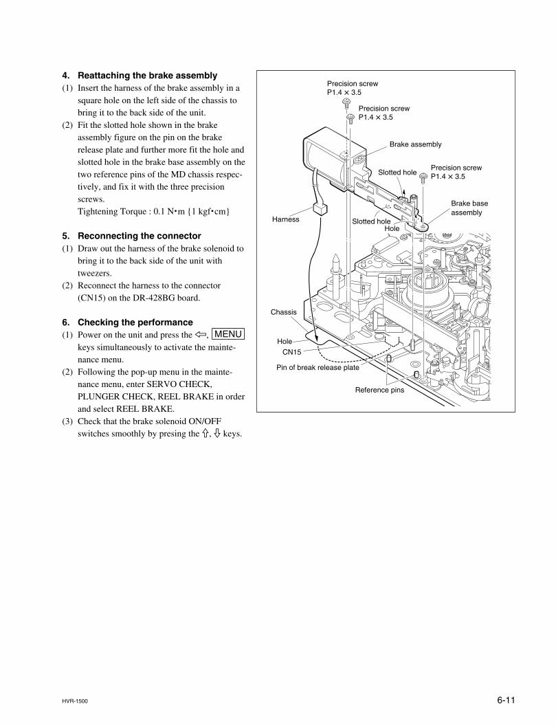
6-11HVR-1500
4. Reattaching the brake assembly(1) Insert the harness of the brake assembly in a
square hole on the left side of the chassis tobring it to the back side of the unit.
(2) Fit the slotted hole shown in the brakeassembly figure on the pin on the brakerelease plate and further more fit the hole andslotted hole in the brake base assembly on thetwo reference pins of the MD chassis respec-tively, and fix it with the three precisionscrews.Tightening Torque : 0.1 N.m {1 kgf.cm}
5. Reconnecting the connector(1) Draw out the harness of the brake solenoid to
bring it to the back side of the unit withtweezers.
(2) Reconnect the harness to the connector(CN15) on the DR-428BG board.
6. Checking the performance(1) Power on the unit and press the 7, [MENU]
keys simultaneously to activate the mainte-nance menu.
(2) Following the pop-up menu in the mainte-nance menu, enter SERVO CHECK,PLUNGER CHECK, REEL BRAKE in orderand select REEL BRAKE.
(3) Check that the brake solenoid ON/OFFswitches smoothly by presing the 9, 0 keys.
Chassis
CN15
Reference pins
Harness
Precision screwP1.4 x 3.5
Precision screwP1.4 x 3.5
Precision screwP1.4 x 3.5
Pin of break release plate
Brake assembly
Brake base assembly
Slotted hole
Slotted holeHole
Hole
6-12 HVR-1500
6-4. Pinch Roller Replacement
Outline
ReplacementRemoving the pinch limiter assembly.Reattaching the pinch limiter assembly.
Adjustment after replacementChecking the tape path adjustment
Note
. The pinch roller is a part of the pinch limiter assembly, therefore replace the pinchlimiter assembly itself when the pinch roller needs to be replaced.
. Prepare a new stop washer when replacing the pinch roller assembly.Stop washer (1.5) : 3-669-465-01
Preparation
1. Set the unit to the unthreading end status.2. Power off the unit.3. Remove the top panel. (Refer to Section 2-7-1.)4. Remove the cassette compartment. (Refer to Section 2-8.)
Tools
. Washer extracting fixture (A) : J-6082-234-A
. Washer mounting fixture Ø1.5 : J-6082-231-A
. Cleaning cloth : 3-184-527-01
. Cleaning fluid : 9-919-573-01
. Grease (SG-941) : 7-662-001-39
. Tweezers
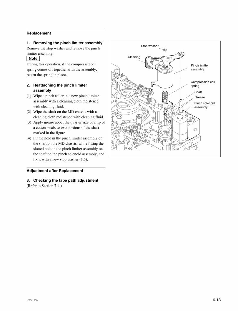
6-13HVR-1500
Replacement
1. Removing the pinch limiter assemblyRemove the stop washer and remove the pinchlimiter assembly.nDuring this operation, if the compressed coilspring comes off together with the assembly,return the spring in place.
2. Reattaching the pinch limiterassembly
(1) Wipe a pinch roller in a new pinch limiterassembly with a cleaning cloth moistenedwith cleaning fluid.
(2) Wipe the shaft on the MD chassis with acleaning cloth moistened with cleaning fluid.
(3) Apply grease about the quarter size of a tip ofa cotton swab, to two portions of the shaftmarked in the figure.
(4) Fit the hole in the pinch limiter assembly onthe shaft on the MD chassis, while fitting theslotted hole in the pinch limiter assembly onthe shaft on the pinch solenoid assembly, andfix it with a new stop washer (1.5).
Adjustment after Replacement
3. Checking the tape path adjustment(Refer to Section 7-4.)
Grease
Shaft
Pinch solenoidassembly
Compression coilspring
Pinch limitterassembly
Stop washer
Cleaning
6-14 HVR-1500
6-5. Elevator Cam Replacement
Outline
ReplacementRemoving the pinch limiter assemblyReplacing the elevator camReattaching the pinch limiter assembly
Adjustment after replacementChacking the tape path adjustment
Note
Prepare two kinds of new stop washers when replacing the elevator cam.Stop washer (1.5) : 3-669-465-01 x 1 (for mounting the pinch limiter assembly)Stop washer (2.3) : 3-669-596-01 x 1 (for mounting the elevator cam)
Preparation
1. Set the unit to the unthreading end status.2. Power off the unit.3. Remove the top panel. (Refer to Section 2-7-1.)4. Remove the cassette compartment. (Refer to Section 2-8.)
Tools
. Washer extracting fixture (A) : J-6082-234-A
. Washer mounting fixture Ø1.5 : J-6082-231-A
. Cleaning cloth : 3-184-527-01
. Cleaning fluid : 9-919-573-01
. Grease (SGL-941) : 7-662-001-39
. Tweezers
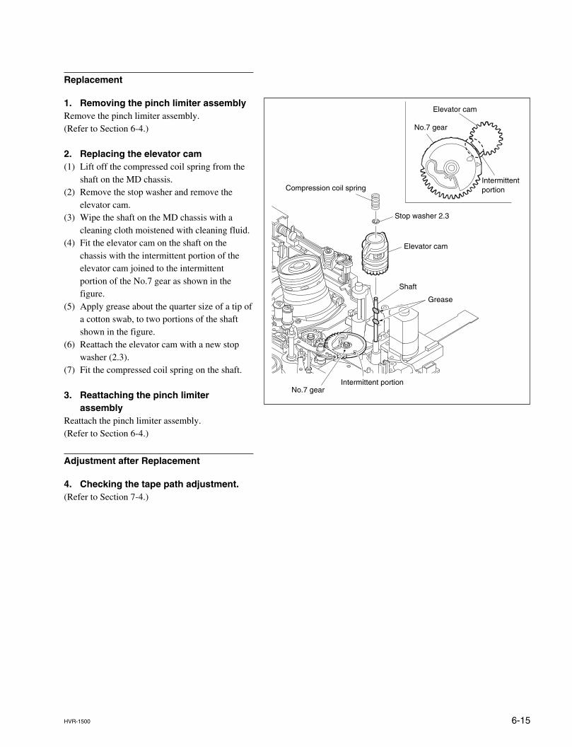
6-15HVR-1500
Replacement
1. Removing the pinch limiter assemblyRemove the pinch limiter assembly.(Refer to Section 6-4.)
2. Replacing the elevator cam(1) Lift off the compressed coil spring from the
shaft on the MD chassis.(2) Remove the stop washer and remove the
elevator cam.(3) Wipe the shaft on the MD chassis with a
cleaning cloth moistened with cleaning fluid.(4) Fit the elevator cam on the shaft on the
chassis with the intermittent portion of theelevator cam joined to the intermittentportion of the No.7 gear as shown in thefigure.
(5) Apply grease about the quarter size of a tip ofa cotton swab, to two portions of the shaftshown in the figure.
(6) Reattach the elevator cam with a new stopwasher (2.3).
(7) Fit the compressed coil spring on the shaft.
3. Reattaching the pinch limiterassembly
Reattach the pinch limiter assembly.(Refer to Section 6-4.)
Adjustment after Replacement
4. Checking the tape path adjustment.(Refer to Section 7-4.)
Grease
No.7 gear
No.7 gear
Intermittent portion
Intermittent portion
Shaft
Stop washer 2.3
Elevator cam
Elevator cam
Compression coil spring
6-16 HVR-1500
6-6. Pinch Solenoid Assembly Replacement
Outline
ReplacementRemoving the pinch limiter assembly.Disconnecting the connector.Replacing the pinch solenoid assembly.Reconnecting the connector.Reattaching the pinch limiter assembly.
Adjustment after replacementChecking the tape path adjustment
Note
Without removal/reattachment of the pinch limiter assembly, the pinch solenoidassembly cannot be replaced.Therefore prepare a new stop washer for replacing the pinch limiter assembly.Stop washer (1.5) : 3-669-465-01 x 1
Preparation
1. Set the unit to the unthreading end status.2. Power off the unit.3. Remove the top panel. (Refer to Section 2-7-1.)4. Remove the cassette compartment. (Refer to Section 2-8.)
Tools
. Torque screwdriver’s bit (for M1.4) : J-6325-110-A
. Torque screwdriver (for 3 kgf.cm) : J-6325-400-A
. Washer extracting fixture (A) : J-6082-234-A
. Washer mounting fixture Ø1.5 : J-6082-231-A
. Tweezers
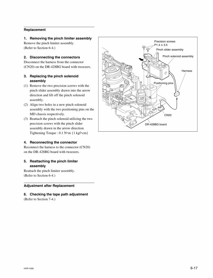
6-17HVR-1500
Precision screwsP1.4 x 3.5
Pinch solenoid assembly
Pinch slider assembly
Positioning pins
CN20
DR-428BG board
Harness
Replacement
1. Removing the pinch limiter assemblyRemove the pinch limiter assembly.(Refer to Section 6-4.)
2. Disconnecting the connectorsDisconnect the harness from the connector(CN20) on the DR-428BG board with tweezers.
3. Replacing the pinch solenoidassembly
(1) Remove the two precision screws with thepinch slider assembly drawn into the arrowdirection and lift off the pinch solenoidassembly.
(2) Align two holes in a new pinch solenoidassembly with the two positioning pins on theMD chassis respectively.
(3) Reattach the pinch solenoid utilizing the twoprecision screws with the pinch sliderassembly drawn in the arrow direction.Tightening Torque : 0.1 N.m {1 kgf.cm}
4. Reconnecting the connectorReconnect the harness to the connector (CN20)on the DR-428BG board with tweezers.
5. Reattaching the pinch limiterassembly
Reattach the pinch limiter assembly.(Refer to Section 6-4.)
Adjustment after Replacement
6. Checking the tape path adjustment(Refer to Section 7-4.)
6-18 HVR-1500
6-7. Reel Motor (T) Assembly Replacement
Outline
ReplacementDisconnecting the connectorMoving the S/T reel tablesRemoving the L push plateRemoving the MIC assemblyRemoving the RMP (T1) retainer assemblyReplacing the reel motor (T) assemblyReattaching the RMP (T1) retainer assemblyReattaching the MIC assemblyReattaching the L push plateReconnecting the connectorChecking the performance
Adjustment after replacementT-REEL ONLY adjustmentTENSION adjustmentTape path adjustment
Note
Without removal/reattachment of the MIC assembly, the reel motor (T) assemblycannot be replaced. Prepare a new stop washer when reattaching the MIC assembly.Stop washer (1.5) : 3-669-465-01 x 1Use care not to lose the polyethylene washer between the base plate and the MICassembly.
Preparation
1. After setting the standard cassette position, set the unit to the unthreading endstatus.
2. Power off the unit.3. Remove the top panel. (Refer to Section 2-7-1.)4. Remove the cassette compartment. (Refer to Section 2-8.)
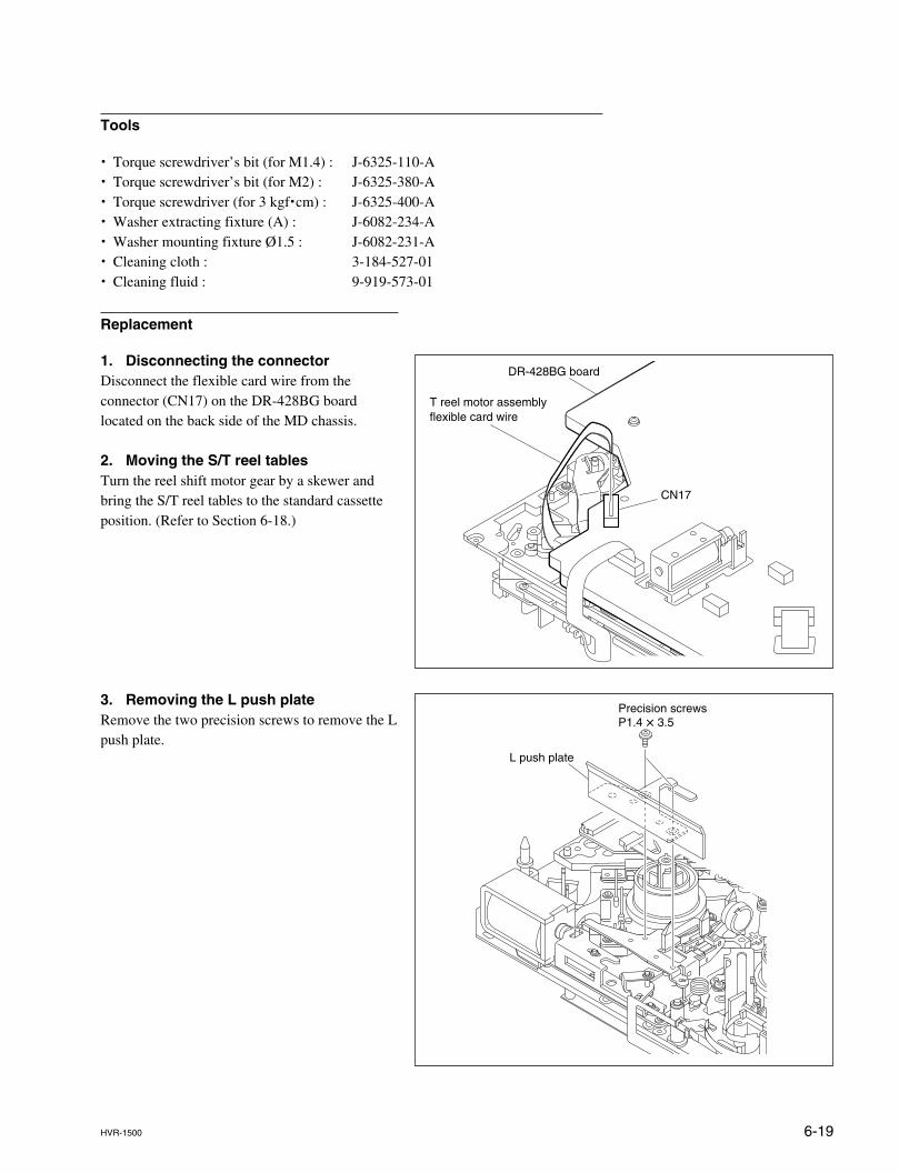
6-19HVR-1500
DR-428BG board
T reel motor assemblyflexible card wire
CN17
Precision screwsP1.4 x 3.5
L push plate
Tools
. Torque screwdriver’s bit (for M1.4) : J-6325-110-A
. Torque screwdriver’s bit (for M2) : J-6325-380-A
. Torque screwdriver (for 3 kgf.cm) : J-6325-400-A
. Washer extracting fixture (A) : J-6082-234-A
. Washer mounting fixture Ø1.5 : J-6082-231-A
. Cleaning cloth : 3-184-527-01
. Cleaning fluid : 9-919-573-01
Replacement
1. Disconnecting the connectorDisconnect the flexible card wire from theconnector (CN17) on the DR-428BG boardlocated on the back side of the MD chassis.
2. Moving the S/T reel tablesTurn the reel shift motor gear by a skewer andbring the S/T reel tables to the standard cassetteposition. (Refer to Section 6-18.)
3. Removing the L push plateRemove the two precision screws to remove the Lpush plate.
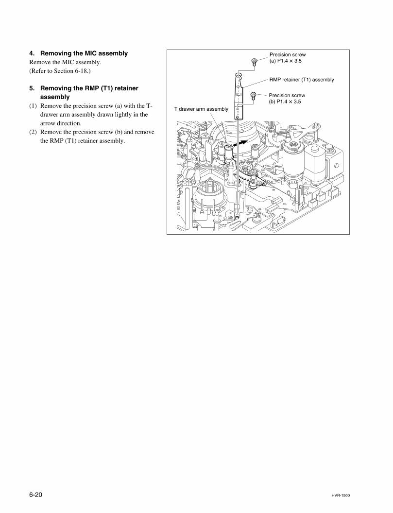
6-20 HVR-1500
Precision screw (a) P1.4 x 3.5
Precision screw (b) P1.4 x 3.5
RMP retainer (T1) assembly
T drawer arm assembly
4. Removing the MIC assemblyRemove the MIC assembly.(Refer to Section 6-18.)
5. Removing the RMP (T1) retainerassembly
(1) Remove the precision screw (a) with the T-drawer arm assembly drawn lightly in thearrow direction.
(2) Remove the precision screw (b) and removethe RMP (T1) retainer assembly.
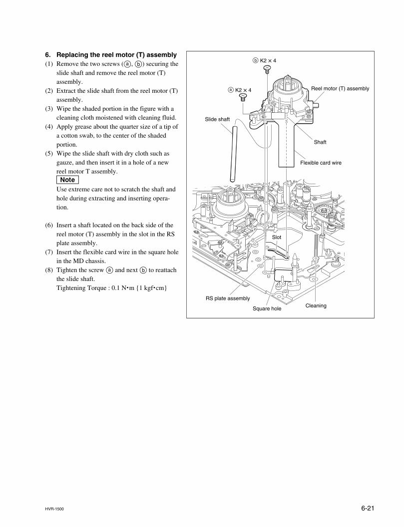
6-21HVR-1500
b K2 x 4
a K2 x 4 Reel motor (T) assembly
Slide shaft
Flexible card wire
Slot
RS plate assembly
Square hole Cleaning
Shaft
6. Replacing the reel motor (T) assembly(1) Remove the two screws (a, b) securing the
slide shaft and remove the reel motor (T)assembly.
(2) Extract the slide shaft from the reel motor (T)assembly.
(3) Wipe the shaded portion in the figure with acleaning cloth moistened with cleaning fluid.
(4) Apply grease about the quarter size of a tip ofa cotton swab, to the center of the shadedportion.
(5) Wipe the slide shaft with dry cloth such asgauze, and then insert it in a hole of a newreel motor T assembly.nUse extreme care not to scratch the shaft andhole during extracting and inserting opera-tion.
(6) Insert a shaft located on the back side of thereel motor (T) assembly in the slot in the RSplate assembly.
(7) Insert the flexible card wire in the square holein the MD chassis.
(8) Tighten the screw a and next b to reattachthe slide shaft.Tightening Torque : 0.1 N.m {1 kgf.cm}
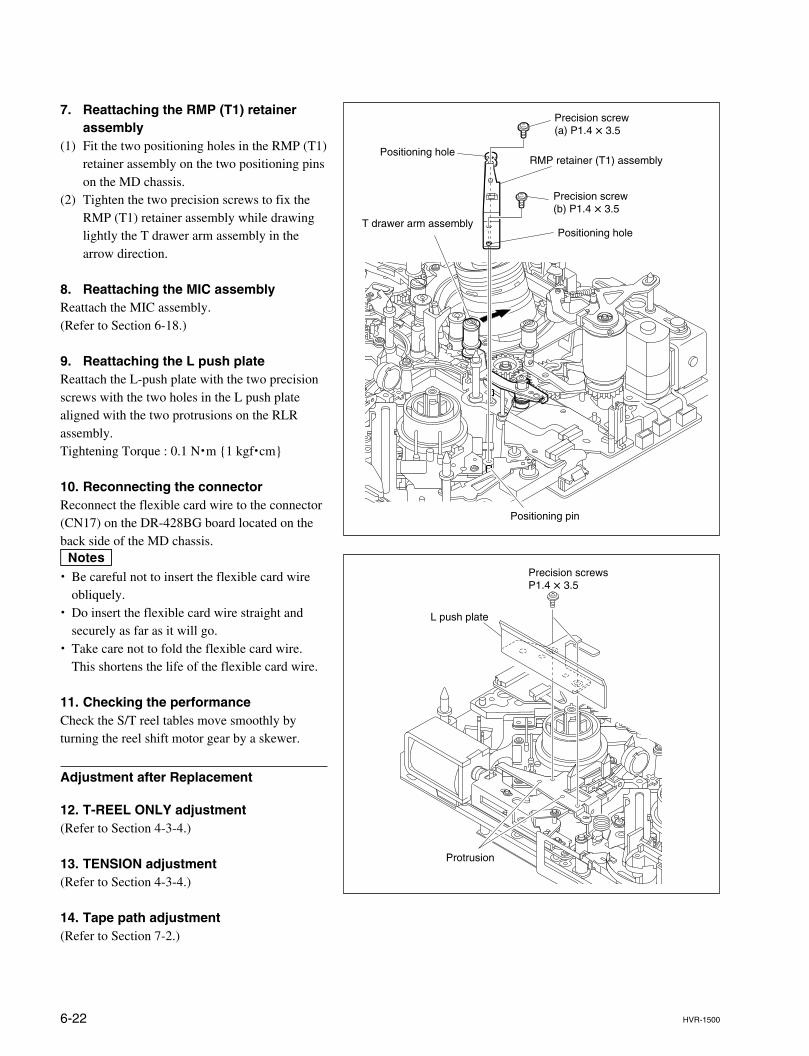
6-22 HVR-1500
7. Reattaching the RMP (T1) retainerassembly
(1) Fit the two positioning holes in the RMP (T1)retainer assembly on the two positioning pinson the MD chassis.
(2) Tighten the two precision screws to fix theRMP (T1) retainer assembly while drawinglightly the T drawer arm assembly in thearrow direction.
8. Reattaching the MIC assemblyReattach the MIC assembly.(Refer to Section 6-18.)
9. Reattaching the L push plateReattach the L-push plate with the two precisionscrews with the two holes in the L push platealigned with the two protrusions on the RLRassembly.Tightening Torque : 0.1 N.m {1 kgf.cm}
10. Reconnecting the connectorReconnect the flexible card wire to the connector(CN17) on the DR-428BG board located on theback side of the MD chassis.m. Be careful not to insert the flexible card wire
obliquely.. Do insert the flexible card wire straight and
securely as far as it will go.. Take care not to fold the flexible card wire.
This shortens the life of the flexible card wire.
11. Checking the performanceCheck the S/T reel tables move smoothly byturning the reel shift motor gear by a skewer.
Adjustment after Replacement
12. T-REEL ONLY adjustment(Refer to Section 4-3-4.)
13. TENSION adjustment(Refer to Section 4-3-4.)
14. Tape path adjustment(Refer to Section 7-2.)
Precision screw (a) P1.4 x 3.5
Precision screw (b) P1.4 x 3.5
RMP retainer (T1) assemblyPositioning hole
Positioning hole
Positioning pin
T drawer arm assembly
Protrusion
Precision screwsP1.4 x 3.5
L push plate
6-23HVR-1500
6-8. Reel Motor (S) Assembly Replacement
Outline
ReplacementDisconnecting the connectorMoving the S/T reel tablesRemoving the RMP (S1) retainer assemblyReplacing the reel motor (S) assemblyReattaching the RMP (S1) retainer assemblyReconnecting the connectorChecking the performance
Adjustment after replacementS-RELL ONLY adjustmentTENSION adjustmentTape path adjustment
Preparation
1. After setting the unit to the standard cassette position, set it to the unthreadingend status.
2. Power off the unit.3. Remove the top panel. (Refer to Section 2-7-1.)4. Remove the cassette compartment. (Refer to Section 2-8.)
Tools
. Torque screwdriver’s bit (for M1.4) : J-6325-110-A
. Torque screwdriver’s bit (for M2) : J-6325-380-A
. Torque screwdriver (for 3 kgf.cm) : J-6325-400-A
. Cleaning cloth : 3-184-527-01
. Cleaning fluid : 9-919-573-01
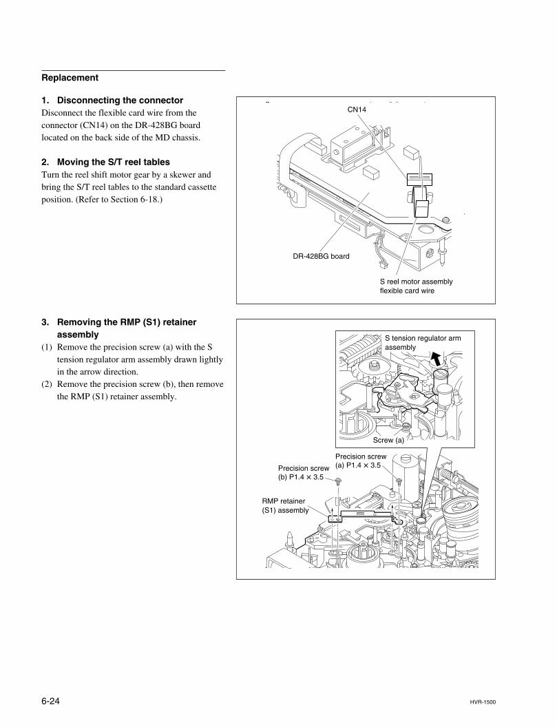
6-24 HVR-1500
DR-428BG board
S reel motor assembly flexible card wire
CN14
Replacement
1. Disconnecting the connectorDisconnect the flexible card wire from theconnector (CN14) on the DR-428BG boardlocated on the back side of the MD chassis.
2. Moving the S/T reel tablesTurn the reel shift motor gear by a skewer andbring the S/T reel tables to the standard cassetteposition. (Refer to Section 6-18.)
3. Removing the RMP (S1) retainerassembly
(1) Remove the precision screw (a) with the Stension regulator arm assembly drawn lightlyin the arrow direction.
(2) Remove the precision screw (b), then removethe RMP (S1) retainer assembly.
RMP retainer(S1) assembly
Precision screw (b) P1.4 x 3.5
Precision screw (a) P1.4 x 3.5
Screw (a)
S tension regulator arm assembly
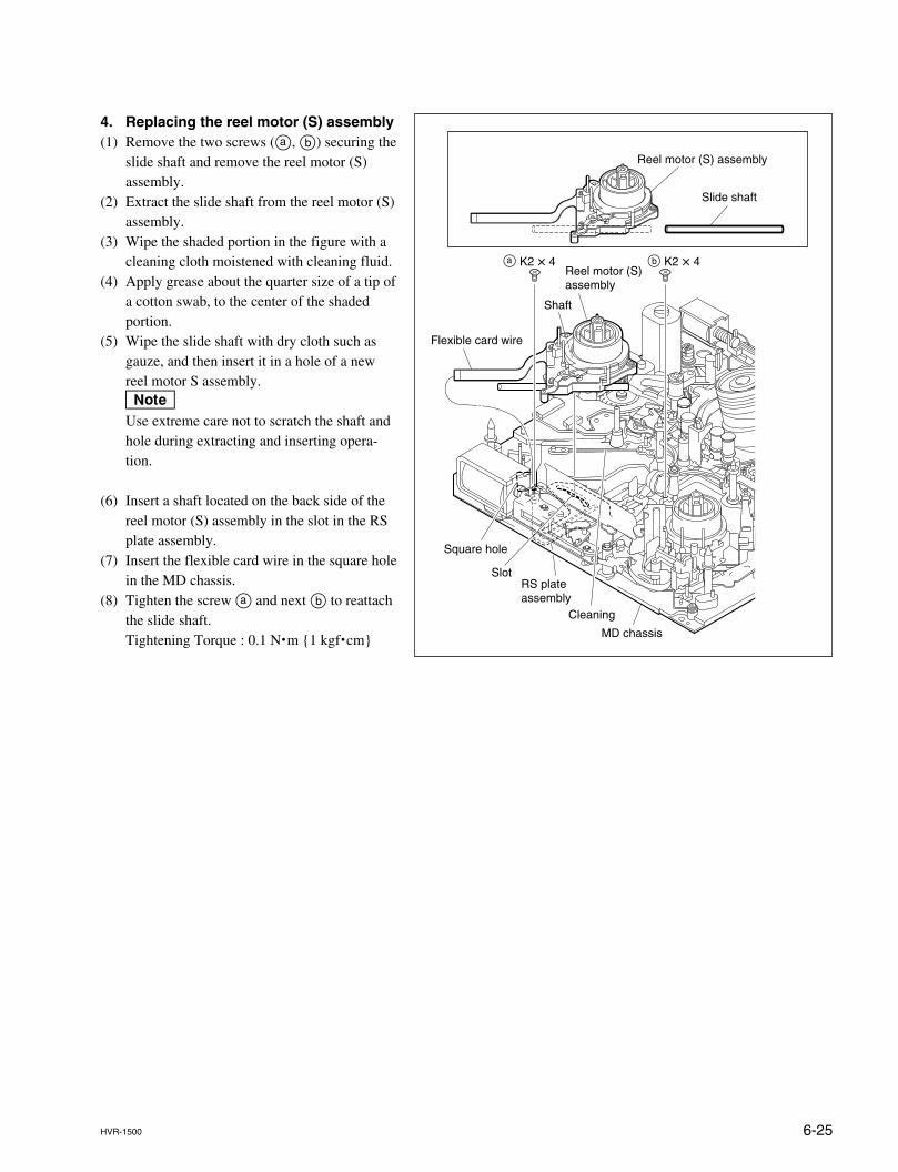
6-25HVR-1500
Reel motor (S) assembly
Shaft
Flexible card wire
Square hole
SlotRS plate assembly
MD chassis
Cleaning
Reel motor (S) assembly
Slide shaft
a K2 x 4 b K2 x 4
4. Replacing the reel motor (S) assembly(1) Remove the two screws (a, b) securing the
slide shaft and remove the reel motor (S)assembly.
(2) Extract the slide shaft from the reel motor (S)assembly.
(3) Wipe the shaded portion in the figure with acleaning cloth moistened with cleaning fluid.
(4) Apply grease about the quarter size of a tip ofa cotton swab, to the center of the shadedportion.
(5) Wipe the slide shaft with dry cloth such asgauze, and then insert it in a hole of a newreel motor S assembly.nUse extreme care not to scratch the shaft andhole during extracting and inserting opera-tion.
(6) Insert a shaft located on the back side of thereel motor (S) assembly in the slot in the RSplate assembly.
(7) Insert the flexible card wire in the square holein the MD chassis.
(8) Tighten the screw a and next b to reattachthe slide shaft.Tightening Torque : 0.1 N.m {1 kgf.cm}
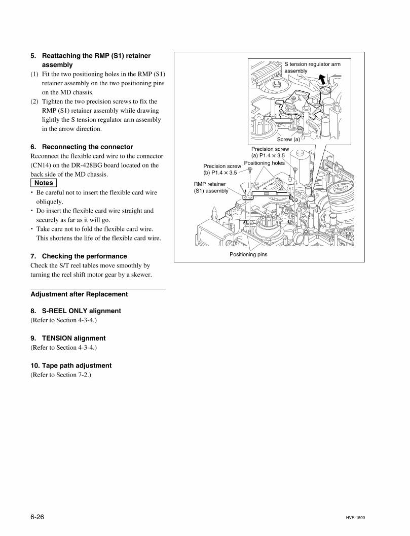
6-26 HVR-1500
5. Reattaching the RMP (S1) retainerassembly
(1) Fit the two positioning holes in the RMP (S1)retainer assembly on the two positioning pinson the MD chassis.
(2) Tighten the two precision screws to fix theRMP (S1) retainer assembly while drawinglightly the S tension regulator arm assemblyin the arrow direction.
6. Reconnecting the connectorReconnect the flexible card wire to the connector(CN14) on the DR-428BG board located on theback side of the MD chassis.m. Be careful not to insert the flexible card wire
obliquely.. Do insert the flexible card wire straight and
securely as far as it will go.. Take care not to fold the flexible card wire.
This shortens the life of the flexible card wire.
7. Checking the performanceCheck the S/T reel tables move smoothly byturning the reel shift motor gear by a skewer.
Adjustment after Replacement
8. S-REEL ONLY alignment(Refer to Section 4-3-4.)
9. TENSION alignment(Refer to Section 4-3-4.)
10. Tape path adjustment(Refer to Section 7-2.)
RMP retainer(S1) assembly
Precision screw (b) P1.4 x 3.5
Precision screw (a) P1.4 x 3.5
Positioning pins
Positioning holes
S tension regulator arm assembly
Screw (a)
6-27HVR-1500
6-9. M Stop Solenoid Replacement
Outline
ReplacementRemoving the M stop drive plate assemblyReplacing the M stop solenoidInstalling the M stop drive plate assembly
Preparation
1. Set the unit to the unthreading end status.2. Power off the unit.3. Remove the bottom plate assembly. (Refer to Section 2-7-2.)4. Remove the DR-428BG board. (Refer to Section 6-26-5.)
Tools
. Torque screwdriver’s bit (for M1.4) : J-6325-110-A
. Torque screwdriver bit (for M2) : J-6325-380-A
. Torque screwdriver (for 3 kgf.cm) : J-6325-400-A
. Locking compound (Three bond-1401B) : 7-432-114-11
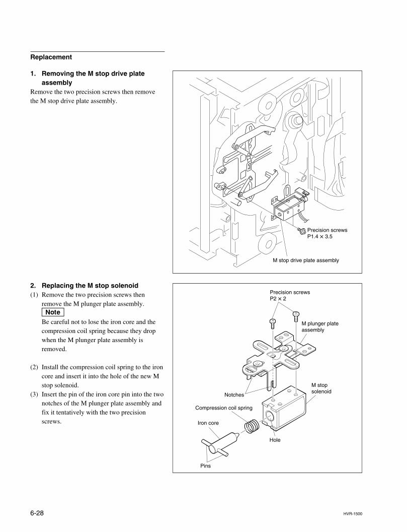
6-28 HVR-1500
Replacement
1. Removing the M stop drive plateassembly
Remove the two precision screws then removethe M stop drive plate assembly.
2. Replacing the M stop solenoid(1) Remove the two precision screws then
remove the M plunger plate assembly.nBe careful not to lose the iron core and thecompression coil spring because they dropwhen the M plunger plate assembly isremoved.
(2) Install the compression coil spring to the ironcore and insert it into the hole of the new Mstop solenoid.
(3) Insert the pin of the iron core pin into the twonotches of the M plunger plate assembly andfix it tentatively with the two precisionscrews.
M stop drive plate assembly
Precision screwsP1.4 x 3.5
M plunger plate assembly
M stop solenoid
Compression coil spring
Iron core
Notches
Hole
Pins
Precision screwsP2 x 2
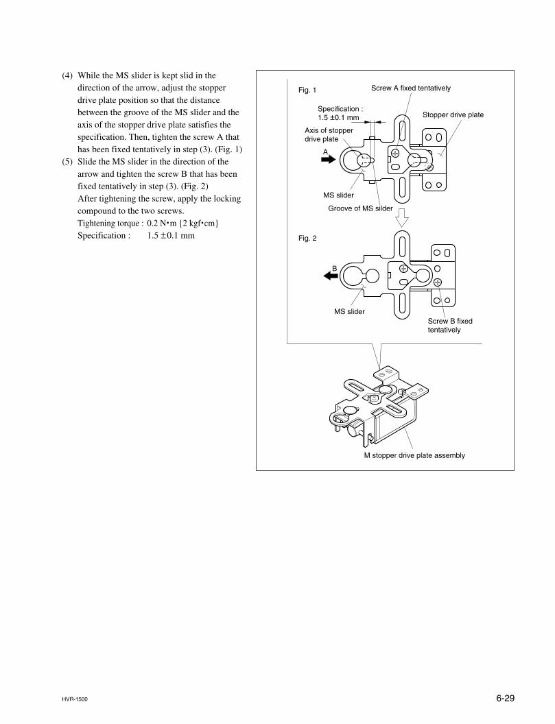
6-29HVR-1500
(4) While the MS slider is kept slid in thedirection of the arrow, adjust the stopperdrive plate position so that the distancebetween the groove of the MS slider and theaxis of the stopper drive plate satisfies thespecification. Then, tighten the screw A thathas been fixed tentatively in step (3). (Fig. 1)
(5) Slide the MS slider in the direction of thearrow and tighten the screw B that has beenfixed tentatively in step (3). (Fig. 2)After tightening the screw, apply the lockingcompound to the two screws.Tightening torque : 0.2 N.m {2 kgf.cm}Specification : 1.5 ±0.1 mm
Stopper drive plate
Axis of stopper drive plate
Screw A fixed tentatively
Screw B fixed tentatively
MS slider
M stopper drive plate assembly
MS slider
Groove of MS silder
Specification :1.5 ±0.1 mm
Fig. 1
Fig. 2
A
B
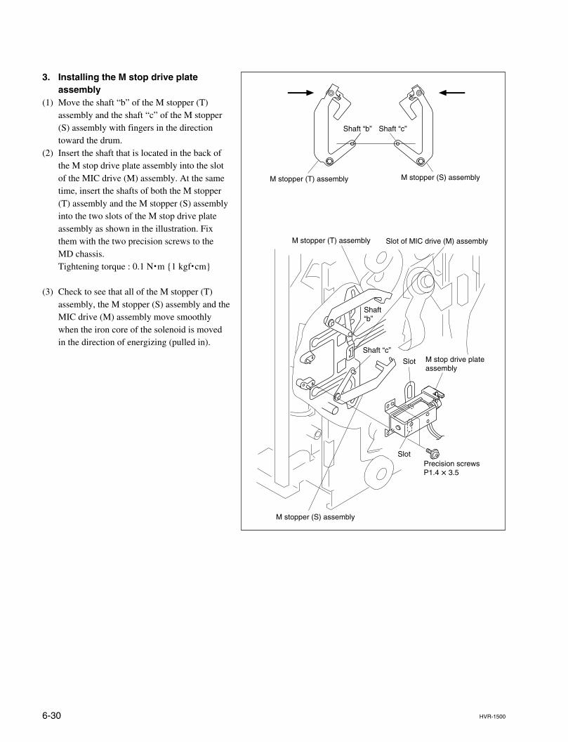
6-30 HVR-1500
3. Installing the M stop drive plateassembly
(1) Move the shaft “b” of the M stopper (T)assembly and the shaft “c” of the M stopper(S) assembly with fingers in the directiontoward the drum.
(2) Insert the shaft that is located in the back ofthe M stop drive plate assembly into the slotof the MIC drive (M) assembly. At the sametime, insert the shafts of both the M stopper(T) assembly and the M stopper (S) assemblyinto the two slots of the M stop drive plateassembly as shown in the illustration. Fixthem with the two precision screws to theMD chassis.Tightening torque : 0.1 N.m {1 kgf.cm}
(3) Check to see that all of the M stopper (T)assembly, the M stopper (S) assembly and theMIC drive (M) assembly move smoothlywhen the iron core of the solenoid is movedin the direction of energizing (pulled in).
Shaft “b”
Shaft “c”
Shaft “b”
Slot
Slot
Slot of MIC drive (M) assembly
M stop drive plate assembly
Precision screwsP1.4 x 3.5
M stopper (S) assembly
M stopper (S) assembly
M stopper (T) assembly
M stopper (T) assembly
Shaft “c”
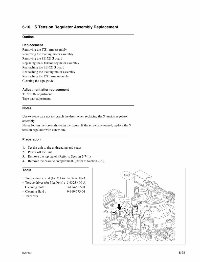
6-31HVR-1500
6-10. S Tension Regulator Assembly Replacement
Outline
ReplacementRemoving the TG1 arm assemblyRemoving the loading motor assemblyRemoving the SE-521G boardReplacing the S tension regulator assemblyReattaching the SE-521G boardReattaching the loading motor assemblyReattaching the TG1 arm assemblyCleaning the tape guide
Adjustment after replacementTENSION adjustmentTape path adjustment
Notes
Use extreme care not to scratch the drum when replacing the S tension regulatorassembly.Never loosen the screw shown in the figure. If the screw is loosened, replace the Stension regulator with a new one.
Preparation
1. Set the unit to the unthreading end status.2. Power off the unit.3. Remove the top panel. (Refer to Section 2-7-1.)4. Remove the cassette compartment. (Refer to Section 2-8.)
Tools
. Torque driver’s bit (for M1.4) : J-6325-110-A
. Torque driver (for 3 kgf.cm) : J-6325-400-A
. Cleaning cloth : 3-184-527-01
. Cleaning fluid : 9-919-573-01
. Tweezers
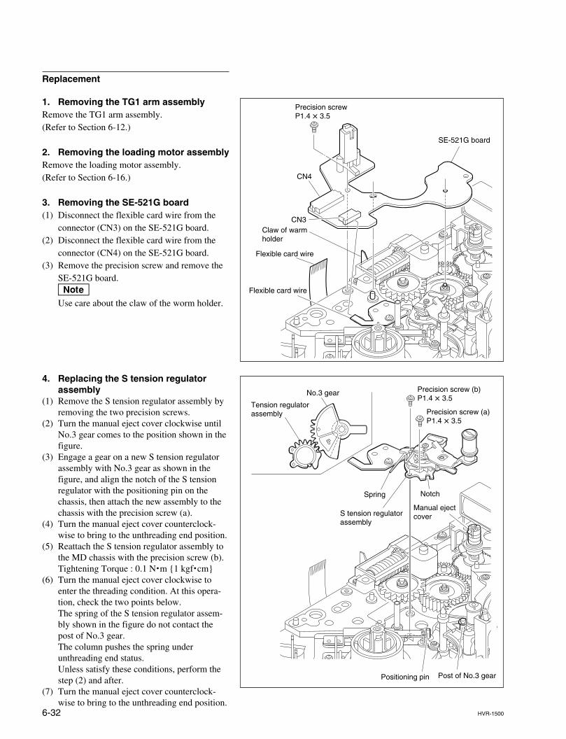
6-32 HVR-1500
CN3
CN4
SE-521G board
Precision screw P1.4 x 3.5
Flexible card wire
Flexible card wire
Claw of warm holder
Replacement
1. Removing the TG1 arm assemblyRemove the TG1 arm assembly.(Refer to Section 6-12.)
2. Removing the loading motor assemblyRemove the loading motor assembly.(Refer to Section 6-16.)
3. Removing the SE-521G board(1) Disconnect the flexible card wire from the
connector (CN3) on the SE-521G board.(2) Disconnect the flexible card wire from the
connector (CN4) on the SE-521G board.(3) Remove the precision screw and remove the
SE-521G board.nUse care about the claw of the worm holder.
4. Replacing the S tension regulatorassembly
(1) Remove the S tension regulator assembly byremoving the two precision screws.
(2) Turn the manual eject cover clockwise untilNo.3 gear comes to the position shown in thefigure.
(3) Engage a gear on a new S tension regulatorassembly with No.3 gear as shown in thefigure, and align the notch of the S tensionregulator with the positioning pin on thechassis, then attach the new assembly to thechassis with the precision screw (a).
(4) Turn the manual eject cover counterclock-wise to bring to the unthreading end position.
(5) Reattach the S tension regulator assembly tothe MD chassis with the precision screw (b).Tightening Torque : 0.1 N.m {1 kgf.cm}
(6) Turn the manual eject cover clockwise toenter the threading condition. At this opera-tion, check the two points below.The spring of the S tension regulator assem-bly shown in the figure do not contact thepost of No.3 gear.The column pushes the spring underunthreading end status.Unless satisfy these conditions, perform thestep (2) and after.
(7) Turn the manual eject cover counterclock-wise to bring to the unthreading end position.
Precision screw (b) P1.4 x 3.5
Precision screw (a) P1.4 x 3.5
No.3 gear
Tension regulator assembly
Spring Notch
S tension regulator assembly
Positioning pin Post of No.3 gear
Manual eject cover
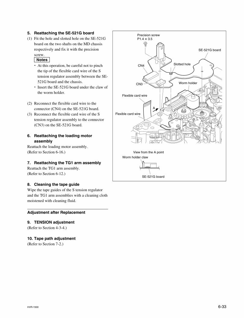
6-33HVR-1500
SE-521G board
CN3
CN4 Slotted hole
Precision screwP1.4 x 3.5
Flexible card wire
Flexible card wire
Worm holder claw
Worm holder
A
SE-521G board
View from the A point
5. Reattaching the SE-521G board(1) Fit the hole and slotted hole on the SE-521G
board on the two shafts on the MD chassisrespectively and fix it with the precisionscrew.m. At this operation, be careful not to pinch
the tip of the flexible card wire of the Stension regulator assembly between the SE-521G board and the chassis.
. Insert the SE-521G board under the claw ofthe worm holder.
(2) Reconnect the flexible card wire to theconnector (CN4) on the SE-521G board.
(3) Reconnect the flexible card wire of the Stension regulator assembly to the connector(CN3) on the SE-521G board.
6. Reattaching the loading motorassembly
Reattach the loading motor assembly.(Refer to Section 6-16.)
7. Reattaching the TG1 arm assemblyReattach the TG1 arm assembly.(Refer to Section 6-12.)
8. Cleaning the tape guideWipe the tape guides of the S tension regulatorand the TG1 arm assemblies with a cleaning clothmoistened with cleaning fluid.
Adjustment after Replacement
9. TENSION adjustment(Refer to Section 4-3-4.)
10. Tape path adjustment(Refer to Section 7-2.)
6-34 HVR-1500
6-11. T Drawer Arm Assembly Replacement
Outline
ReplacementRemoving the T drawer arm assemblyChecking the mounting position of the T gearReattaching the T drawer arm assemblyCleaning the tape guide
Adjustment after replacementChecking the tape path adjustment
Note
Use extreme care no to scratch the drum when replacing the T drawer arm assembly.
Preparation
1. Let the unit into the unthreading position.2. Power off the unit.3. Remove the top panel. (Refer to Section 2-7-1.)4. Remove the cassette compartment. (Refer to Section 2-8.)
Tools
. Cleaning cloth : 3-184-527-01
. Cleaning fluid : 9-919-573-01
. Tweezers
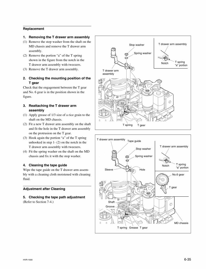
6-35HVR-1500
No.6 gear
T gear
T gearT spring
T spring “a” portion
T drawer arm assembly
Stop washer
Spring washer
T drawer arm assembly
Hole
MD chassis
Sleeve
Tape guide
Notch
Grease
Groove
Shaft
T gearT spring
T spring “a” portion
T drawer arm assembly
T drawer arm assembly
Notch
Stop washer
Spring washer
Replacement
1. Removing the T drawer arm assembly(1) Remove the stop washer from the shaft on the
MD chassis and remove the T drawer armassembly.
(2) Remove the portion “a” of the T springshown in the figure from the notch in theT drawer arm assembly with tweezers.
(3) Remove the T drawer arm assembly.
2. Checking the mounting position of theT gear
Check that the engagement between the T gearand No. 6 gear is in the position shown in thefigure.
3. Reattaching the T drawer armassembly
(1) Apply grease of 1/3 size of a rice grain to theshaft on the MD chassis.
(2) Fit a new T drawer arm assembly on the shaftand fit the hole in the T drawer arm assemblyon the protrusion on the T gear.
(3) Hook again the portion “a” of the T springunhooked in step 1- (2) on the notch in theT drawer arm assembly with tweezers.
(4) Fit the spring washer on the shaft on the MDchassis and fix it with the stop washer.
4. Cleaning the tape guideWipe the tape guide on the T drawer arm assem-bly with a cleaning cloth moistened with cleaningfluid.
Adjustment after Cleaning
5. Checking the tape path adjustment(Refer to Section 7-4.)
6-36 HVR-1500
6-12. TG1 Arm Assembly Replacement
Outline
ReplacementReplacing the TG1 arm assemblyCleaning the tape guide
Adjustment after replacementTENSION adjustmentChecking the tape path adjustment
Note
Do avoid touching with bare hands to the tape cleaner a part of in TG1 arm assem-bly. Sharpness of the edge on the tape cleaner may cause a hand cut, therefore useextreme care when replacing the TG1 arm assembly.
Preparation
1. Set the unit to the unthreading end status.2. Power off the unit.3. Remove the top panel. (Refer to Section 2-7-1.)4. Remove the cassette compartment. (Refer to Section 2-8.)
Tools
. Torque screwdriver’s bit (for M1.4) : J-6325-110-A
. Torque screwdriver (for 3 kgf.cm) : J-6325-400-A
. Cleaning cloth : 3-184-527-01
. Cleaning fluid : 9-919-573-01
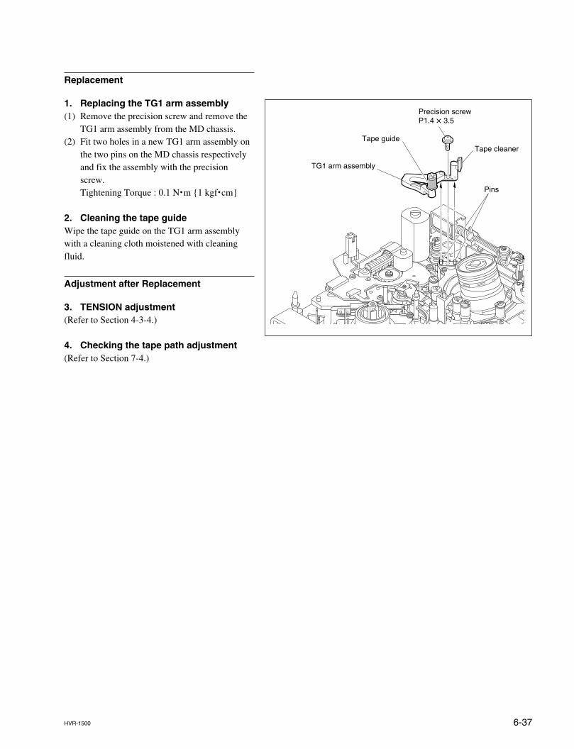
6-37HVR-1500
Precision screwP1.4 x 3.5
Pins
Tape guide
TG1 arm assembly
Tape cleaner
Replacement
1. Replacing the TG1 arm assembly(1) Remove the precision screw and remove the
TG1 arm assembly from the MD chassis.(2) Fit two holes in a new TG1 arm assembly on
the two pins on the MD chassis respectivelyand fix the assembly with the precisionscrew.Tightening Torque : 0.1 N.m {1 kgf.cm}
2. Cleaning the tape guideWipe the tape guide on the TG1 arm assemblywith a cleaning cloth moistened with cleaningfluid.
Adjustment after Replacement
3. TENSION adjustment(Refer to Section 4-3-4.)
4. Checking the tape path adjustment(Refer to Section 7-4.)
6-38 HVR-1500
6-13. TG8 Arm Assembly Replacement
Outline
ReplacementReplacing the TG8 arm assemblyCleaning the tape guide
Adjustment after replacementChecking the tape path adjustment
Preparation
1. Set the unit to the unthreading end status.2. Power off the unit.3. Remove the top panel. (Refer to Section 2-7-1.)4. Remove the cassette compartment. (Refer to Section 2-8.)
Tools
. Torque screwdriver’s bit (for M1.4) : J-6325-110-A
. Torque screwdriver (for 3 kgf.cm) : J-6325-400-A
. Washer extracting fixture (A) : J-6082-234-A
. Washer mounting fixture Ø1.5 : J-6082-231-A
. Cleaning cloth : 3-184-527-01
. Cleaning fluid : 9-919-573-01
. Tweezers
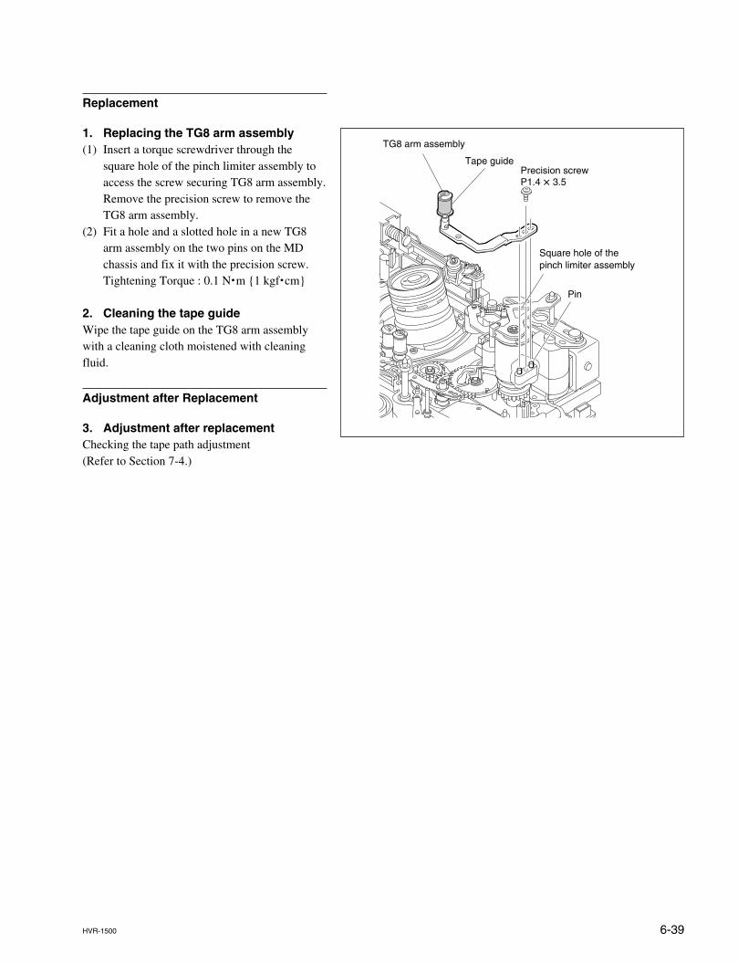
6-39HVR-1500
Replacement
1. Replacing the TG8 arm assembly(1) Insert a torque screwdriver through the
square hole of the pinch limiter assembly toaccess the screw securing TG8 arm assembly.Remove the precision screw to remove theTG8 arm assembly.
(2) Fit a hole and a slotted hole in a new TG8arm assembly on the two pins on the MDchassis and fix it with the precision screw.Tightening Torque : 0.1 N.m {1 kgf.cm}
2. Cleaning the tape guideWipe the tape guide on the TG8 arm assemblywith a cleaning cloth moistened with cleaningfluid.
Adjustment after Replacement
3. Adjustment after replacementChecking the tape path adjustment(Refer to Section 7-4.)
Precision screwP1.4 x 3.5
TG8 arm assembly
Tape guide
Pin
Square hole of thepinch limiter assembly
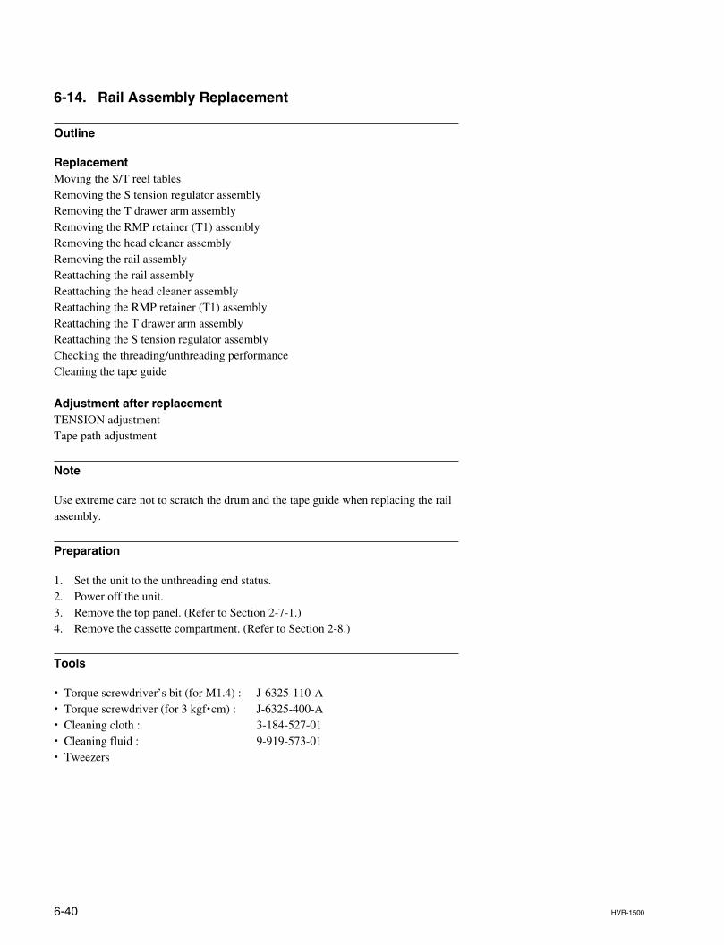
6-40 HVR-1500
6-14. Rail Assembly Replacement
Outline
ReplacementMoving the S/T reel tablesRemoving the S tension regulator assemblyRemoving the T drawer arm assemblyRemoving the RMP retainer (T1) assemblyRemoving the head cleaner assemblyRemoving the rail assemblyReattaching the rail assemblyReattaching the head cleaner assemblyReattaching the RMP retainer (T1) assemblyReattaching the T drawer arm assemblyReattaching the S tension regulator assemblyChecking the threading/unthreading performanceCleaning the tape guide
Adjustment after replacementTENSION adjustmentTape path adjustment
Note
Use extreme care not to scratch the drum and the tape guide when replacing the railassembly.
Preparation
1. Set the unit to the unthreading end status.2. Power off the unit.3. Remove the top panel. (Refer to Section 2-7-1.)4. Remove the cassette compartment. (Refer to Section 2-8.)
Tools
. Torque screwdriver’s bit (for M1.4) : J-6325-110-A
. Torque screwdriver (for 3 kgf.cm) : J-6325-400-A
. Cleaning cloth : 3-184-527-01
. Cleaning fluid : 9-919-573-01
. Tweezers
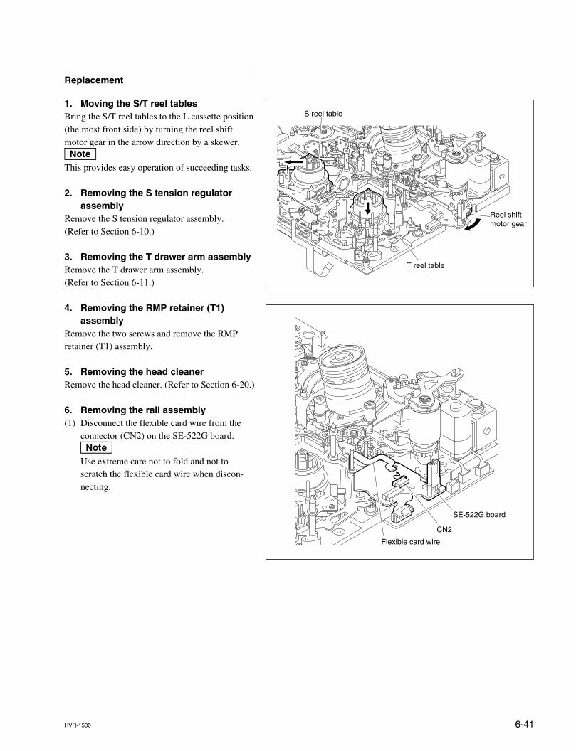
6-41HVR-1500
SE-522G board
CN2
Flexible card wire
Replacement
1. Moving the S/T reel tablesBring the S/T reel tables to the L cassette position(the most front side) by turning the reel shiftmotor gear in the arrow direction by a skewer.nThis provides easy operation of succeeding tasks.
2. Removing the S tension regulatorassembly
Remove the S tension regulator assembly.(Refer to Section 6-10.)
3. Removing the T drawer arm assemblyRemove the T drawer arm assembly.(Refer to Section 6-11.)
4. Removing the RMP retainer (T1)assembly
Remove the two screws and remove the RMPretainer (T1) assembly.
5. Removing the head cleanerRemove the head cleaner. (Refer to Section 6-20.)
6. Removing the rail assembly(1) Disconnect the flexible card wire from the
connector (CN2) on the SE-522G board.nUse extreme care not to fold and not toscratch the flexible card wire when discon-necting.
Reel shiftmotor gear
T reel table
S reel table
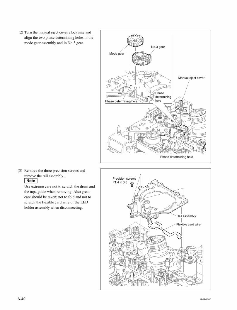
6-42 HVR-1500
Phase determining hole
Phase determining hole
Mode gear
No.3 gear
Manual eject cover
Phase determining hole
(2) Turn the manual eject cover clockwise andalign the two phase determining holes in themode gear assembly and in No.3 gear.
(3) Remove the three precision screws andremove the rail assembly.nUse extreme care not to scratch the drum andthe tape guide when removing. Also greatcare should be taken; not to fold and not toscratch the flexible card wire of the LEDholder assembly when disconnecting.
Precision screwsP1.4 x 3.5
Rail assembly
Flexible card wire
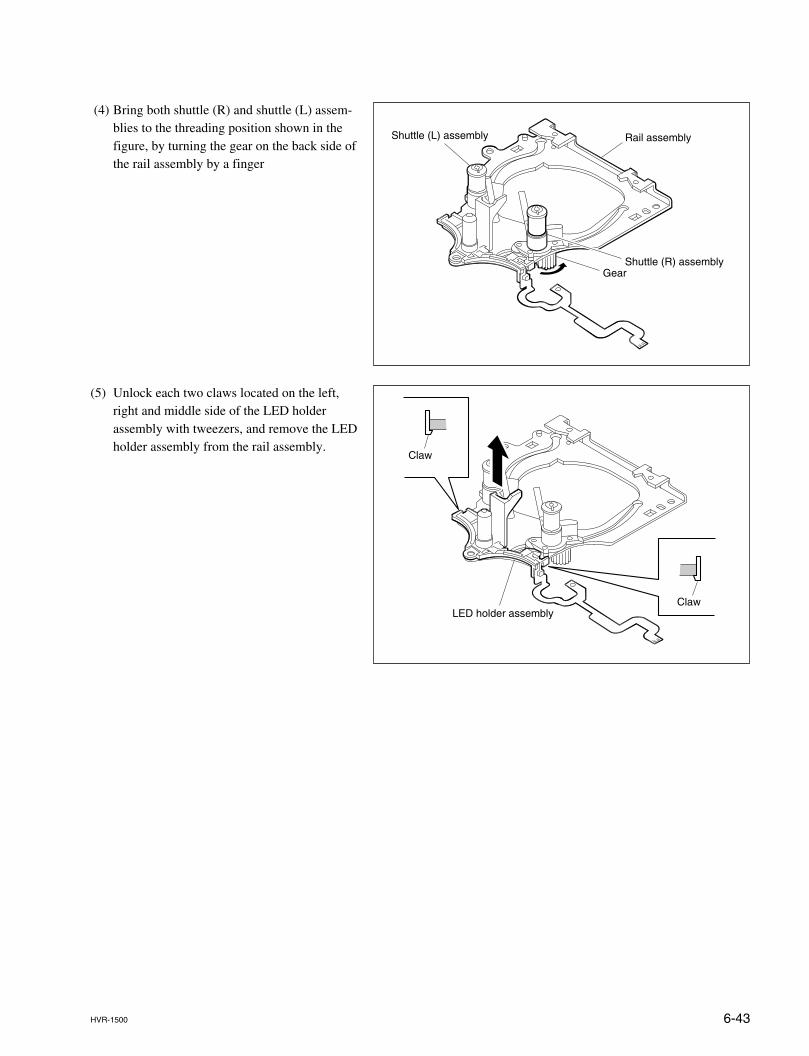
6-43HVR-1500
(4) Bring both shuttle (R) and shuttle (L) assem-blies to the threading position shown in thefigure, by turning the gear on the back side ofthe rail assembly by a finger
Shuttle (L) assembly
Gear
Rail assembly
Shuttle (R) assembly
(5) Unlock each two claws located on the left,right and middle side of the LED holderassembly with tweezers, and remove the LEDholder assembly from the rail assembly.
Claw
ClawLED holder assembly
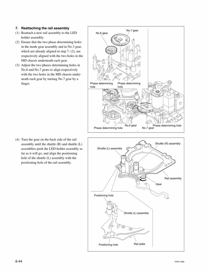
6-44 HVR-1500
7. Reattaching the rail assembly(1) Reattach a new rail assembly to the LED
holder assembly.(2) Ensure that the two phase determining holes
in the mode gear assembly and in No.3 gear,which are already aligned in step 7- (2), arerespectively aligned with the two holes in theMD chassis underneath each gear.
(3) Adjust the two phases determining holes inNo.6 and No.7 gears to align respectivelywith the two holes in the MD chassis under-neath each gear by turning No.7 gear by afinger.
No.6 gearNo.7 gear
Phase determining holePhase determining hole
No.6 gearNo.7 gear
Phase determininghole
Phase determininghole
(4) Turn the gear on the back side of the railassembly until the shuttle (R) and shuttle (L)assemblies push the LED holder assembly asfar as it will go, and align the positioninghole of the shuttle (L) assembly with thepositioning hole of the rail assembly.
Shuttle (L) assembly
Shuttle (L) assembly
Gear
Rail assembly
Shuttle (R) assembly
Positioning hole
Positioning hole Rail plate
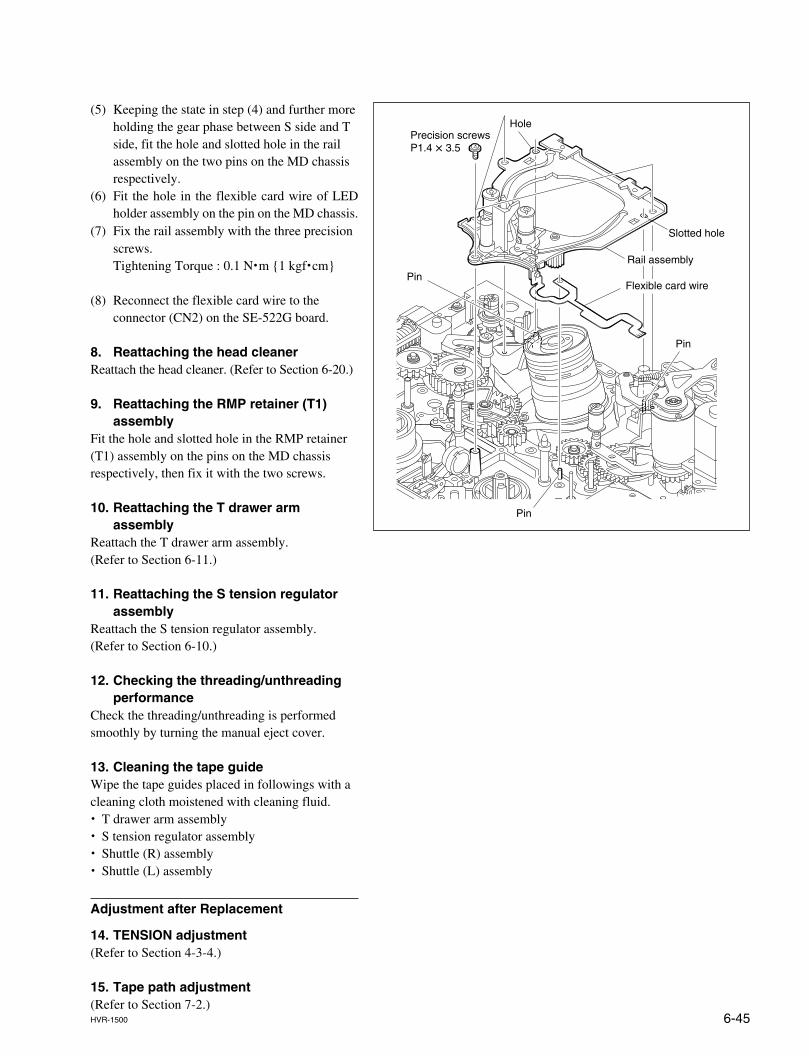
6-45HVR-1500
(5) Keeping the state in step (4) and further moreholding the gear phase between S side and Tside, fit the hole and slotted hole in the railassembly on the two pins on the MD chassisrespectively.
(6) Fit the hole in the flexible card wire of LEDholder assembly on the pin on the MD chassis.
(7) Fix the rail assembly with the three precisionscrews.Tightening Torque : 0.1 N.m {1 kgf.cm}
(8) Reconnect the flexible card wire to theconnector (CN2) on the SE-522G board.
8. Reattaching the head cleanerReattach the head cleaner. (Refer to Section 6-20.)
9. Reattaching the RMP retainer (T1)assembly
Fit the hole and slotted hole in the RMP retainer(T1) assembly on the pins on the MD chassisrespectively, then fix it with the two screws.
10. Reattaching the T drawer armassembly
Reattach the T drawer arm assembly.(Refer to Section 6-11.)
11. Reattaching the S tension regulatorassembly
Reattach the S tension regulator assembly.(Refer to Section 6-10.)
12. Checking the threading/unthreadingperformance
Check the threading/unthreading is performedsmoothly by turning the manual eject cover.
13. Cleaning the tape guideWipe the tape guides placed in followings with acleaning cloth moistened with cleaning fluid.. T drawer arm assembly. S tension regulator assembly. Shuttle (R) assembly. Shuttle (L) assembly
Adjustment after Replacement
14. TENSION adjustment(Refer to Section 4-3-4.)
15. Tape path adjustment(Refer to Section 7-2.)
Precision screwsP1.4 x 3.5
Rail assembly
Slotted hole
Hole
Pin
Pin
Pin
Flexible card wire
6-46 HVR-1500
6-15. Capstan Motor Replacement
Outline
ReplacementRemoving the DR-428BG boardReplacing the capstan motorReattaching the DR-428BG boardCleaning the capstan shaft
Adjustment after replacementCAPSTAN ONLY adjustmentChecking the tape path adjustment
Preparation
1. Set the unit in to the unthreading end status.2. Power off the unit.3. Remove the top panel. (Refer to Section 2-7-1.)4. Remove the bottom panel. (Refer to Section 2-7-2.)5. Remove the cassette compartment. (Refer to Section 2-8.)
Tools
. Torque screwdriver’s bit (for M1.4) : J-6325-110-A
. Torque screwdriver (for 3 kgf.cm) : J-6325-400-A
. Cleaning cloth : 3-184-527-01
. Cleaning fluid : 9-919-573-01
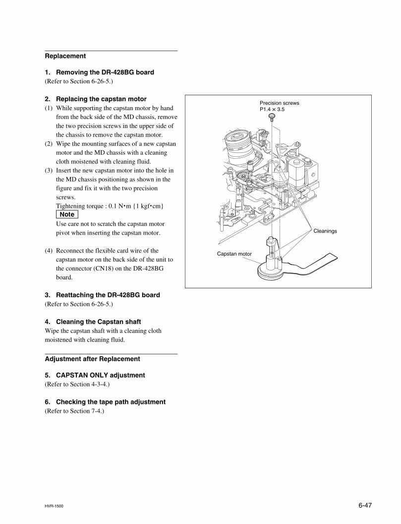
6-47HVR-1500
Replacement
1. Removing the DR-428BG board(Refer to Section 6-26-5.)
2. Replacing the capstan motor(1) While supporting the capstan motor by hand
from the back side of the MD chassis, removethe two precision screws in the upper side ofthe chassis to remove the capstan motor.
(2) Wipe the mounting surfaces of a new capstanmotor and the MD chassis with a cleaningcloth moistened with cleaning fluid.
(3) Insert the new capstan motor into the hole inthe MD chassis positioning as shown in thefigure and fix it with the two precisionscrews.Tightening torque : 0.1 N.m {1 kgf.cm}nUse care not to scratch the capstan motorpivot when inserting the capstan motor.
(4) Reconnect the flexible card wire of thecapstan motor on the back side of the unit tothe connector (CN18) on the DR-428BGboard.
3. Reattaching the DR-428BG board(Refer to Section 6-26-5.)
4. Cleaning the Capstan shaftWipe the capstan shaft with a cleaning clothmoistened with cleaning fluid.
Adjustment after Replacement
5. CAPSTAN ONLY adjustment(Refer to Section 4-3-4.)
6. Checking the tape path adjustment(Refer to Section 7-4.)
Capstan motor
Cleanings
Precision screwsP1.4 x 3.5
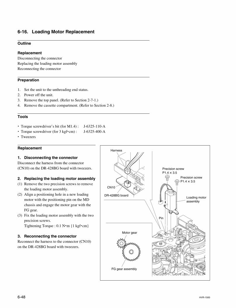
6-48 HVR-1500
Precision screwP1.4 x 3.5
Precision screwP1.4 x 3.5
Loading motorassembly
Pin
DR-428BG board
CN10
Harness
Motor gear
FG gear assembly
6-16. Loading Motor Replacement
Outline
ReplacementDisconnecting the connectorReplacing the loading motor assemblyReconnecting the connector
Preparation
1. Set the unit to the unthreading end status.2. Power off the unit.3. Remove the top panel. (Refer to Section 2-7-1.)4. Remove the cassette compartment. (Refer to Section 2-8.)
Tools
. Torque screwdriver’s bit (for M1.4) : J-6325-110-A
. Torque screwdriver (for 3 kgf.cm) : J-6325-400-A
. Tweezers
Replacement
1. Disconnecting the connectorDisconnect the harness from the connector(CN10) on the DR-428BG board with tweezers.
2. Replacing the loading motor assembly(1) Remove the two precision screws to remove
the loading motor assembly.(2) Align a positioning hole in a new loading
motor with the positioning pin on the MDchassis and engage the motor gear with theFG gear.
(3) Fix the loading motor assembly with the twoprecision screws.Tightening Torque : 0.1 N.m {1 kgf.cm}
3. Reconnecting the connectorReconnect the harness to the connector (CN10)on the DR-428BG board with tweezers.

6-49HVR-1500
6-17. Reel Shift Motor Assembly Replacement
Outline
ReplacementRemoving the pinch limiter assemblyRemoving the pinch solenoid assemblyReplacing the reel shift motor assemblyReattaching the pinch solenoid assemblyReattaching the pinch limiter assembly
Note
Prepare a new stop washer when replacing the reel shift motor assembly.Stop washer (1.5) : 3-669-465-01 x 1 (for mounting the pinch limiter assembly)
Preparation
1. Set the unit to the unthreading end status.2. Power off the unit.3. Remove the top panel. (Refer to Section 2-7-1.)4. Remove the cassette compartment. (Refer to Section 2-8.)
Tools
. Torque screwdriver’s bit (for M1.4) : J-6325-110-A
. Torque screwdriver (for 3 kgf.cm) : J-6325-400-A
. Washer extracting fixture (A) : J-6082-234-A
. Washer mounting fixture Ø1.5 : J-6082-231-A
. Cleaning cloth : 3-184-527-01
. Cleaning fluid : 9-919-573-01
. Tweezers
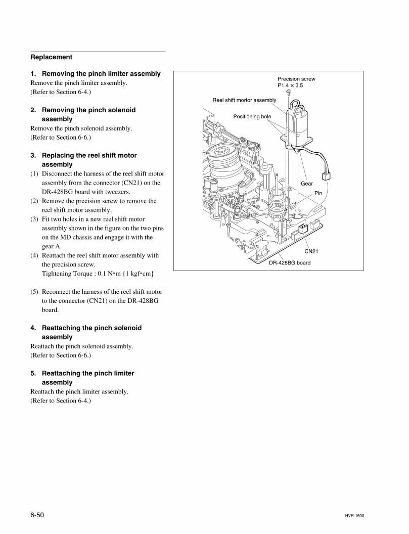
6-50 HVR-1500
CN21
Precision screwP1.4 x 3.5
DR-428BG board
Gear
Pin
Positioning hole
Reel shift mortor assembly
Replacement
1. Removing the pinch limiter assemblyRemove the pinch limiter assembly.(Refer to Section 6-4.)
2. Removing the pinch solenoidassembly
Remove the pinch solenoid assembly.(Refer to Section 6-6.)
3. Replacing the reel shift motorassembly
(1) Disconnect the harness of the reel shift motorassembly from the connector (CN21) on theDR-428BG board with tweezers.
(2) Remove the precision screw to remove thereel shift motor assembly.
(3) Fit two holes in a new reel shift motorassembly shown in the figure on the two pinson the MD chassis and engage it with thegear A.
(4) Reattach the reel shift motor assembly withthe precision screw.Tightening Torque : 0.1 N.m {1 kgf.cm}
(5) Reconnect the harness of the reel shift motorto the connector (CN21) on the DR-428BGboard.
4. Reattaching the pinch solenoidassembly
Reattach the pinch solenoid assembly.(Refer to Section 6-6.)
5. Reattaching the pinch limiterassembly
Reattach the pinch limiter assembly.(Refer to Section 6-4.)
6-51HVR-1500
6-18. MIC Assembly Replacement
Outline
ReplacementDisconnecting the flexible card wireMoving the S/T reel tablesRemoving the L push plateRemoving the MIC springReplacing the MIC assemblyMoving the S/T reel tablesReattaching the MIC springReattaching the L push plateReconnecting the flexible card wire
Note
Prepare a new stop washer when replacing the MIC assembly.Stop washer (1.5) : 3-699-465-01Do avoid touching the terminal on the MIC holder and wiping it with cleaning fluid.When need cleaning, wipe it carefully with a soft dry cloth.Use care not to lose a poly-slider washer between the base plate and the MICassembly.
Preparation
1. Set the unit to the unthreading end status.2. Power off the unit.3. Remove the top panel. (Refer to Section 2-7-1.)4. Remove the cassette compartment. (Refer to Section 2-8.)
Tools
. Torque screwdriver’s bit (for M1.4) : J-6325-110-A
. Torque screwdriver (for 3 kgf.cm) : J-6325-400-A
. Washer extracting fixture (A) : J-6082-234-A
. Washer mounting fixture Ø1.5 : J-6082-231-A
. Tweezers
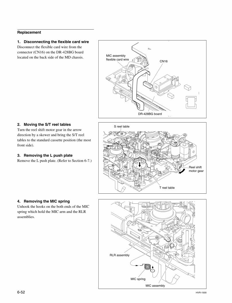
6-52 HVR-1500
CN16
MIC assembly flexible card wire
DR-428BG board
Replacement
1. Disconnecting the flexible card wireDisconnect the flexible card wire from theconnector (CN16) on the DR-428BG boardlocated on the back side of the MD chassis.
2. Moving the S/T reel tablesTurn the reel shift motor gear in the arrowdirection by a skewer and bring the S/T reeltables to the standard cassette position (the mostfront side).
3. Removing the L push plateRemove the L push plate. (Refer to Section 6-7.)
4. Removing the MIC springUnhook the hooks on the both ends of the MICspring which hold the MIC arm and the RLRassemblies.
MIC spring
RLR assembly
MIC assembly
Reel shiftmotor gear
T reel table
S reel table
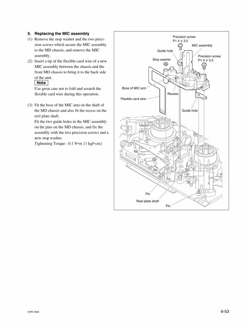
6-53HVR-1500
5. Replacing the MIC assembly(1) Remove the stop washer and the two preci-
sion screws which secure the MIC assemblyto the MD chassis, and remove the MICassembly.
(2) Insert a tip of the flexible card wire of a newMIC assembly between the chassis and thefront MD chassis to bring it to the back sideof the unit.nUse great care not to fold and scratch theflexible card wire during this operation.
(3) Fit the boss of the MIC arm on the shaft ofthe MD chassis and also fit the recess on thereel plate shaft.Fit the two guide holes in the MIC assemblyon the pins on the MD chassis, and fix theassembly with the two precision screws and anew stop washer.Tightening Torque : 0.1 N.m {1 kgf.cm}
Precision screwP1.4 x 3.5
Precision screwP1.4 x 3.5Stop washer
MIC assembly
Guide hole
Guide hole
Pin
Pin
Flexible card wire
Boss of MIC arm
Recess
Reel plate shaft
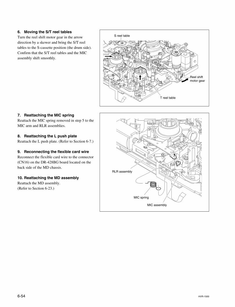
6-54 HVR-1500
6. Moving the S/T reel tablesTurn the reel shift motor gear in the arrowdirection by a skewer and bring the S/T reeltables to the S-cassette position (the drum side).Confirm that the S/T reel tables and the MICassembly shift smoothly.
7. Reattaching the MIC springReattach the MIC spring removed in step 5 to theMIC arm and RLR assemblies.
8. Reattaching the L push plateReattach the L push plate. (Refer to Section 6-7.)
9. Reconnecting the flexible card wireReconnect the flexible card wire to the connector(CN16) on the DR-428BG board located on theback side of the MD chassis.
10. Reattaching the MD assemblyReattach the MD assembly.(Refer to Section 6-23.)
MIC spring
RLR assembly
MIC assembly
Reel shiftmotor gear
T reel table
S reel table
6-55HVR-1500
6-19. MIC Holder Assembly Replacement
Outline
ReplacementRemoving the MIC assemblyReplacing the MIC holder assemblyReattaching the MIC assembly
Note
Prepare new stop washers when replacing the MIC holder.Stop washer (1.2) : 3-559-408-11 x 2 (for mounting the MIC holder assembly)Stop washer (1.5) : 3-669-465-01 x 1 (for mounting the MIC assembly)Do avoid touching the terminal on the MIC holder and wiping it with cleaning fluid.When need cleaning, wipe it carefully with a soft dry cloth.Use care not to lose a poly-slider washer between the base plate and the MICassembly.
Preparation
1. Set the unit to the unthreading end status.2. Power off the unit.3. Remove the top panel. (Refer to Section 2-7-1.)4. Remove the cassette compartment. (Refer to Section 2-8.)
Tools
. Torque screwdriver’s bit (for M1.4) : J-6325-110-A
. Torque screwdriver (for 3 kgf.cm) : J-6325-400-A
. Washer extracting fixture (A) : J-6082-234-A
. Washer mounting fixture Ø1.5 : J-6082-231-A
. Washer mounting fixture Ø1.2 : J-6082-232-A
. Tweezers
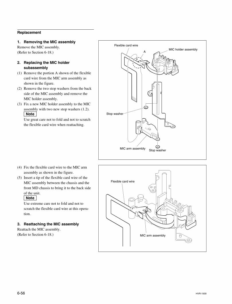
6-56 HVR-1500
Replacement
1. Removing the MIC assemblyRemove the MIC assembly.(Refer to Section 6-18.)
2. Replacing the MIC holdersubassembly
(1) Remove the portion A shown of the flexiblecard wire from the MIC arm assembly asshown in the figure.
(2) Remove the two stop washers from the backside of the MIC assembly and remove theMIC holder assembly.
(3) Fix a new MIC holder assembly to the MICassembly with two new stop washers (1.2).nUse great care not to fold and not to scratchthe flexible card wire when reattaching.
AMIC holder assembly
Flexible card wire
Stop washer
Stop washerMIC arm assembly
(4) Fix the flexible card wire to the MIC armassembly as shown in the figure.
(5) Insert a tip of the flexible card wire of theMIC assembly between the chassis and thefront MD chassis to bring it to the back sideof the unit.nUse extreme care not to fold and not toscratch the flexible card wire at this opera-tion.
3. Reattaching the MIC assemblyReattach the MIC assembly.(Refer to Section 6-18.)
Flexible card wire
MIC arm assembly
6-57HVR-1500
6-20. HC Roller Assembly Replacement
Outline
ReplacementDisconnecting the connectorRemoving the head cleaner assemblyReplacing the HC roller assemblyReattaching the head cleaner assemblyChecking the performance of the head cleaner assemblyReconnecting the connector
Note
Prepare a new stop washer when replacing the HC roller assembly.Stop washer (0.8) : 3-315-414-31 x 1Bare-handed touch to the HC roller assembly is prohibited. Do put on cloth glovesbefore replacing.
Preparation
1. Set the unit to the unthreading end status.2. Power off the unit.3. Remove the top panel. (Refer to Section 2-7-1.)
Tools
. Torque screwdriver’s bit (for M1.4) : J-6325-110-A
. Torque screwdriver (for 3 kgf.cm) : J-6325-400-A
. Washer extracting fixture (A) : J-6082-234-A
. Washer mounting fixture Ø1.8 : J-6082-233-A
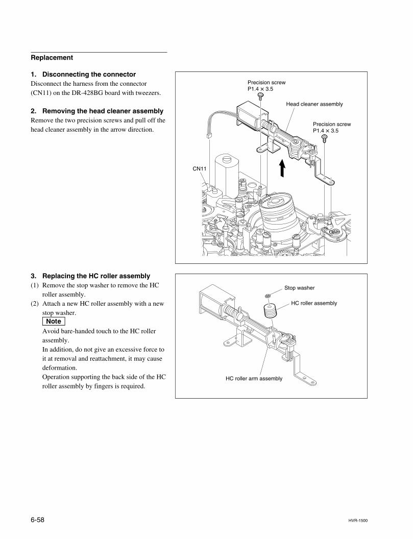
6-58 HVR-1500
Replacement
1. Disconnecting the connectorDisconnect the harness from the connector(CN11) on the DR-428BG board with tweezers.
2. Removing the head cleaner assemblyRemove the two precision screws and pull off thehead cleaner assembly in the arrow direction.
3. Replacing the HC roller assembly(1) Remove the stop washer to remove the HC
roller assembly.(2) Attach a new HC roller assembly with a new
stop washer.nAvoid bare-handed touch to the HC rollerassembly.In addition, do not give an excessive force toit at removal and reattachment, it may causedeformation.Operation supporting the back side of the HCroller assembly by fingers is required.
Precision screwP1.4 x 3.5
Head cleaner assembly
CN11
Precision screwP1.4 x 3.5
HC roller assembly
HC roller arm assembly
Stop washer
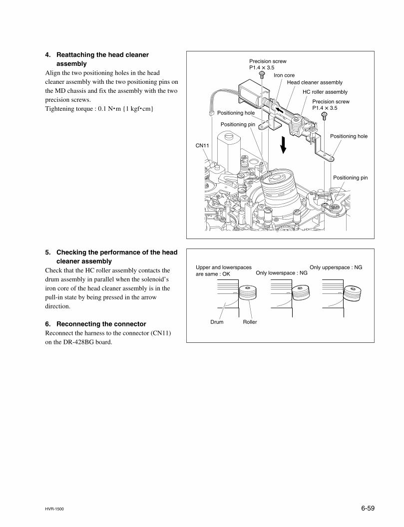
6-59HVR-1500
4. Reattaching the head cleanerassembly
Align the two positioning holes in the headcleaner assembly with the two positioning pins onthe MD chassis and fix the assembly with the twoprecision screws.Tightening torque : 0.1 N.m {1 kgf.cm}
5. Checking the performance of the headcleaner assembly
Check that the HC roller assembly contacts thedrum assembly in parallel when the solenoid’siron core of the head cleaner assembly is in thepull-in state by being pressed in the arrowdirection.
6. Reconnecting the connectorReconnect the harness to the connector (CN11)on the DR-428BG board.
Precision screwP1.4 x 3.5
Head cleaner assemblyIron core
CN11
Positioning hole
Positioning hole
Positioning pin
Positioning pin
Precision screwP1.4 x 3.5
HC roller assembly
Drum Roller
Upper and lowerspaces are same : OK Only lowerspace : NG
Only upperspace : NG
6-60 HVR-1500
6-21. Head Cleaner Solenoid Replacement
Outline
ReplacementRemoving the head cleaner assemblyReplacing the head cleaner solenoidReattaching the head cleaner assemblyChecking the performance of the head cleaner assembly
Preparation
1. Set the unit to the unthreading end status.2. Power off the unit.3. Remove the top panel. (Refer to Section 2-7-1.)
Tools
. Torque screwdriver’s bit (for M1.4) : J-6325-110-A
. Torque screwdriver (for 3 kgf.cm) : J-6325-400-A
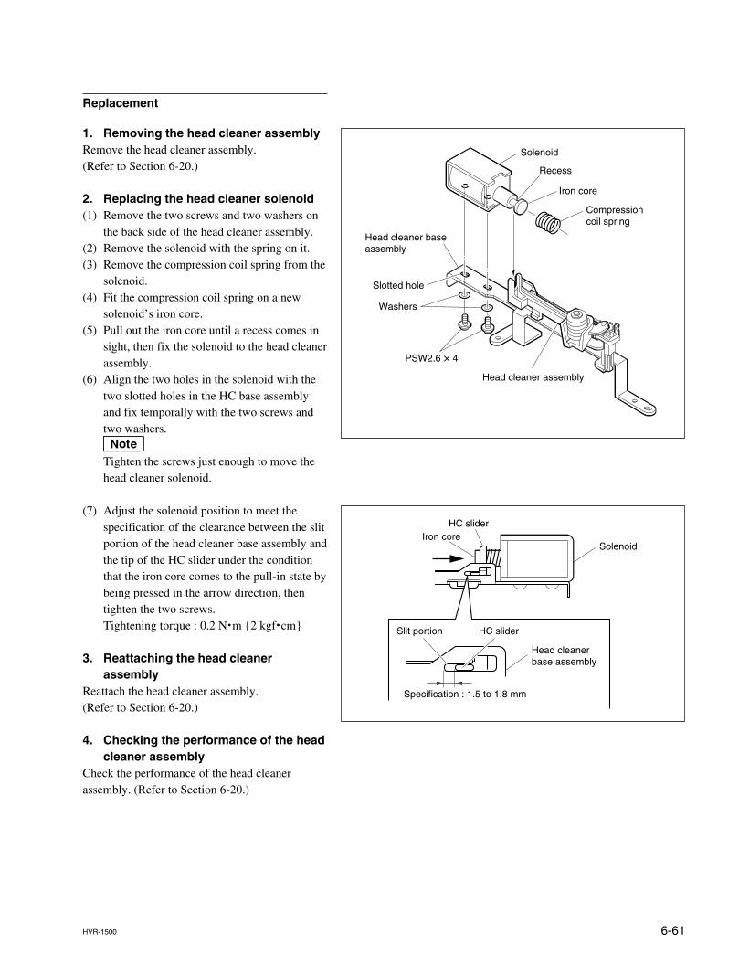
6-61HVR-1500
Washers
PSW2.6 x 4
Solenoid
Recess
Iron core
Compressioncoil spring
Head cleaner baseassembly
Head cleaner assembly
Slotted hole
Replacement
1. Removing the head cleaner assemblyRemove the head cleaner assembly.(Refer to Section 6-20.)
2. Replacing the head cleaner solenoid(1) Remove the two screws and two washers on
the back side of the head cleaner assembly.(2) Remove the solenoid with the spring on it.(3) Remove the compression coil spring from the
solenoid.(4) Fit the compression coil spring on a new
solenoid’s iron core.(5) Pull out the iron core until a recess comes in
sight, then fix the solenoid to the head cleanerassembly.
(6) Align the two holes in the solenoid with thetwo slotted holes in the HC base assemblyand fix temporally with the two screws andtwo washers.nTighten the screws just enough to move thehead cleaner solenoid.
(7) Adjust the solenoid position to meet thespecification of the clearance between the slitportion of the head cleaner base assembly andthe tip of the HC slider under the conditionthat the iron core comes to the pull-in state bybeing pressed in the arrow direction, thentighten the two screws.Tightening torque : 0.2 N.m {2 kgf.cm}
3. Reattaching the head cleanerassembly
Reattach the head cleaner assembly.(Refer to Section 6-20.)
4. Checking the performance of the headcleaner assembly
Check the performance of the head cleanerassembly. (Refer to Section 6-20.)
Solenoid
HC sliderIron core
Head cleaner base assembly
Specification : 1.5 to 1.8 mm
HC sliderSlit portion
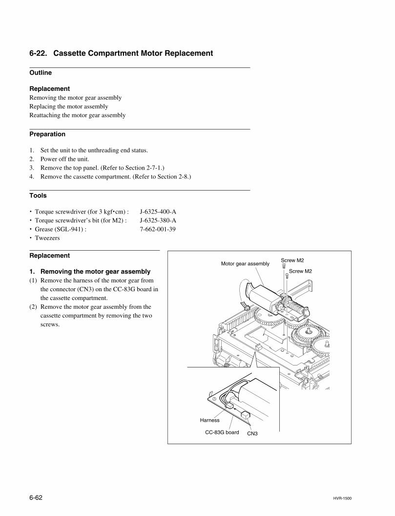
6-62 HVR-1500
Motor gear assembly
CC-83G board
Harness
CN3
Screw M2
Screw M2
6-22. Cassette Compartment Motor Replacement
Outline
ReplacementRemoving the motor gear assemblyReplacing the motor assemblyReattaching the motor gear assembly
Preparation
1. Set the unit to the unthreading end status.2. Power off the unit.3. Remove the top panel. (Refer to Section 2-7-1.)4. Remove the cassette compartment. (Refer to Section 2-8.)
Tools
. Torque screwdriver (for 3 kgf.cm) : J-6325-400-A
. Torque screwdriver’s bit (for M2) : J-6325-380-A
. Grease (SGL-941) : 7-662-001-39
. Tweezers
Replacement
1. Removing the motor gear assembly(1) Remove the harness of the motor gear from
the connector (CN3) on the CC-83G board inthe cassette compartment.
(2) Remove the motor gear assembly from thecassette compartment by removing the twoscrews.
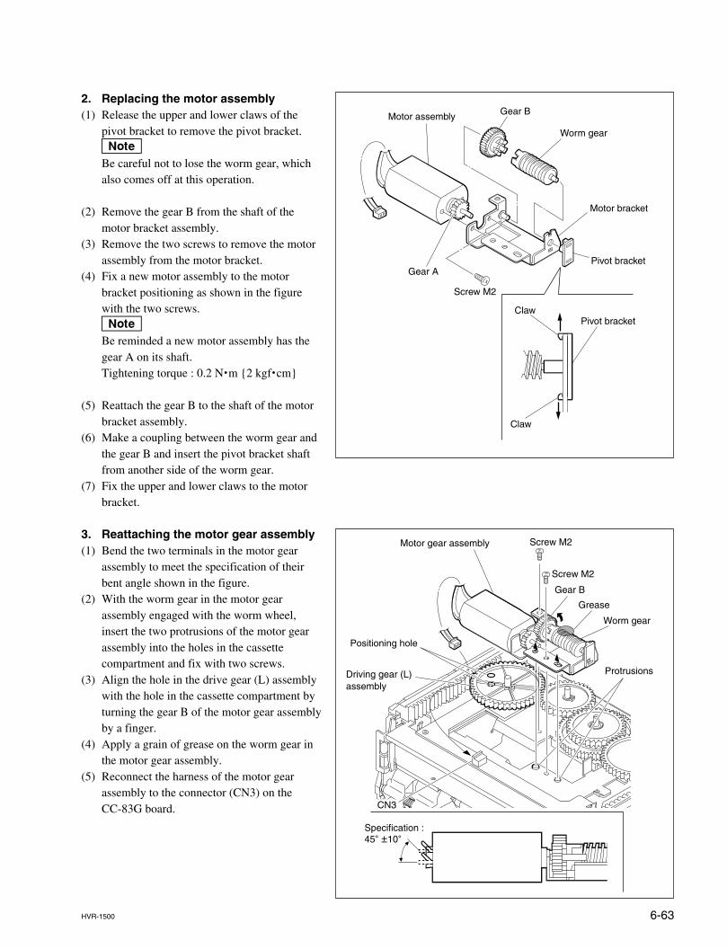
6-63HVR-1500
2. Replacing the motor assembly(1) Release the upper and lower claws of the
pivot bracket to remove the pivot bracket.nBe careful not to lose the worm gear, whichalso comes off at this operation.
(2) Remove the gear B from the shaft of themotor bracket assembly.
(3) Remove the two screws to remove the motorassembly from the motor bracket.
(4) Fix a new motor assembly to the motorbracket positioning as shown in the figurewith the two screws.nBe reminded a new motor assembly has thegear A on its shaft.Tightening torque : 0.2 N.m {2 kgf.cm}
(5) Reattach the gear B to the shaft of the motorbracket assembly.
(6) Make a coupling between the worm gear andthe gear B and insert the pivot bracket shaftfrom another side of the worm gear.
(7) Fix the upper and lower claws to the motorbracket.
3. Reattaching the motor gear assembly(1) Bend the two terminals in the motor gear
assembly to meet the specification of theirbent angle shown in the figure.
(2) With the worm gear in the motor gearassembly engaged with the worm wheel,insert the two protrusions of the motor gearassembly into the holes in the cassettecompartment and fix with two screws.
(3) Align the hole in the drive gear (L) assemblywith the hole in the cassette compartment byturning the gear B of the motor gear assemblyby a finger.
(4) Apply a grain of grease on the worm gear inthe motor gear assembly.
(5) Reconnect the harness of the motor gearassembly to the connector (CN3) on theCC-83G board.
Claw
Claw
Pivot bracket
Pivot bracket
Motor bracket
Screw M2
Worm gear
Motor assembly Gear B
Gear A
Motor gear assembly
Grease
Gear B
Worm gear
Screw M2
Screw M2
Protrusions
Positioning hole
Driving gear (L)assembly
CN3
Specification : 45d ±10d
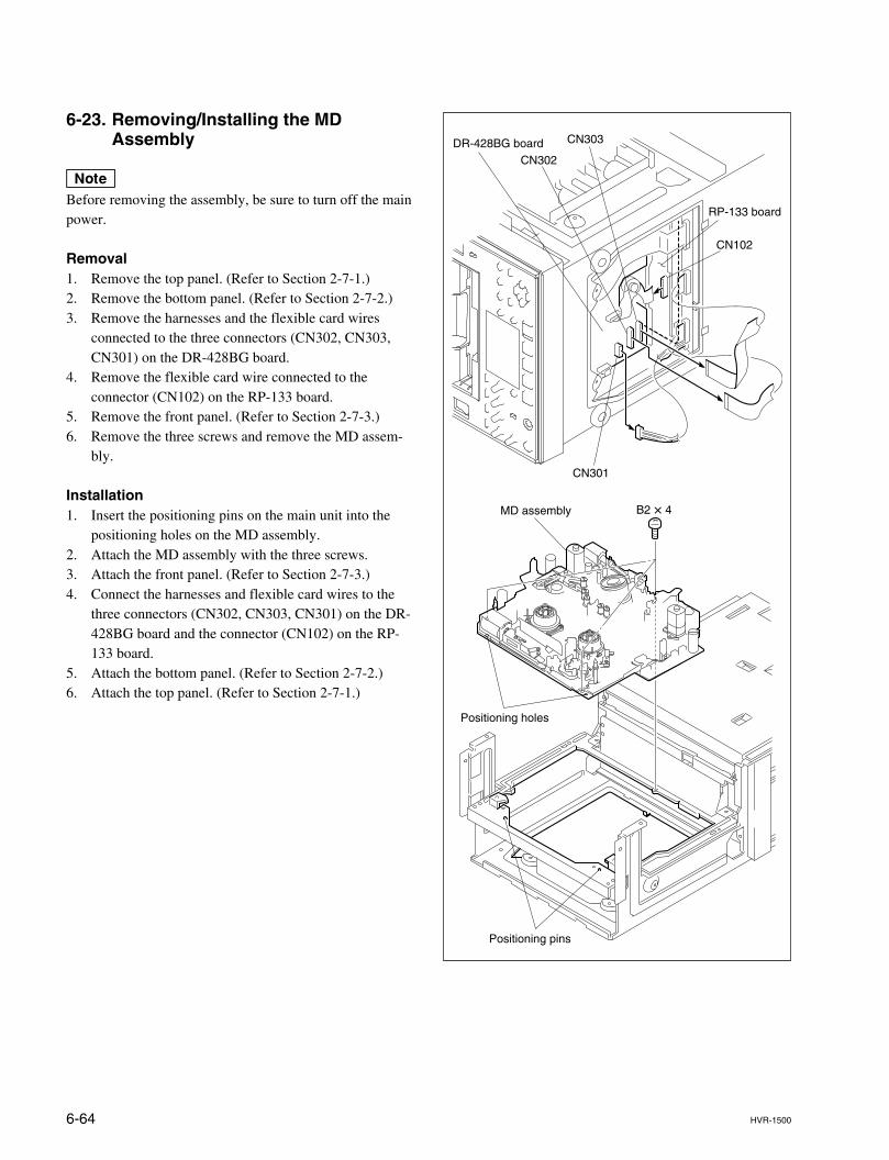
6-64 HVR-1500
B2 x 4MD assembly
Positioning pins
Positioning holes
CN301
CN302DR-428BG board CN303
CN102
RP-133 board
6-23. Removing/Installing the MDAssembly
nBefore removing the assembly, be sure to turn off the mainpower.
Removal1. Remove the top panel. (Refer to Section 2-7-1.)2. Remove the bottom panel. (Refer to Section 2-7-2.)3. Remove the harnesses and the flexible card wires
connected to the three connectors (CN302, CN303,CN301) on the DR-428BG board.
4. Remove the flexible card wire connected to theconnector (CN102) on the RP-133 board.
5. Remove the front panel. (Refer to Section 2-7-3.)6. Remove the three screws and remove the MD assem-
bly.
Installation1. Insert the positioning pins on the main unit into the
positioning holes on the MD assembly.2. Attach the MD assembly with the three screws.3. Attach the front panel. (Refer to Section 2-7-3.)4. Connect the harnesses and flexible card wires to the
three connectors (CN302, CN303, CN301) on the DR-428BG board and the connector (CN102) on the RP-133 board.
5. Attach the bottom panel. (Refer to Section 2-7-2.)6. Attach the top panel. (Refer to Section 2-7-1.)
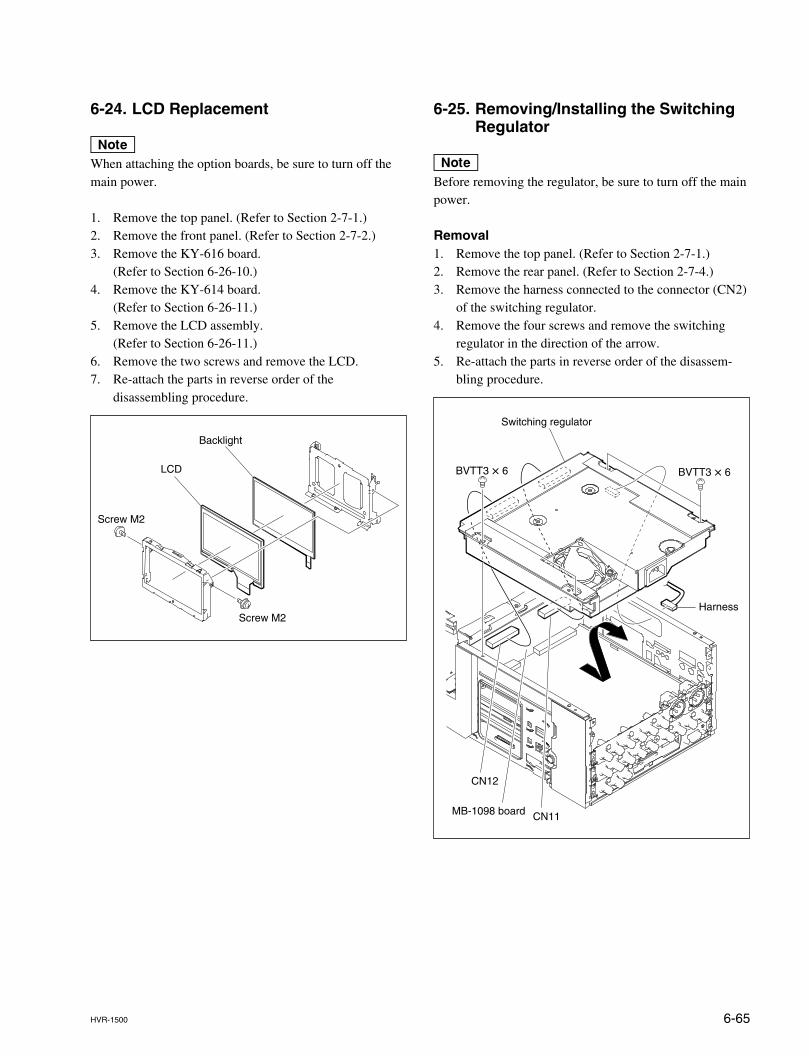
6-65HVR-1500
6-24. LCD Replacement
nWhen attaching the option boards, be sure to turn off themain power.
1. Remove the top panel. (Refer to Section 2-7-1.)2. Remove the front panel. (Refer to Section 2-7-2.)3. Remove the KY-616 board.
(Refer to Section 6-26-10.)4. Remove the KY-614 board.
(Refer to Section 6-26-11.)5. Remove the LCD assembly.
(Refer to Section 6-26-11.)6. Remove the two screws and remove the LCD.7. Re-attach the parts in reverse order of the
disassembling procedure.
Switching regulator
Harness
MB-1098 board
BVTT3 x 6BVTT3 x 6
CN12
CN11
6-25. Removing/Installing the SwitchingRegulator
nBefore removing the regulator, be sure to turn off the mainpower.
Removal1. Remove the top panel. (Refer to Section 2-7-1.)2. Remove the rear panel. (Refer to Section 2-7-4.)3. Remove the harness connected to the connector (CN2)
of the switching regulator.4. Remove the four screws and remove the switching
regulator in the direction of the arrow.5. Re-attach the parts in reverse order of the disassem-
bling procedure.
Backlight
Screw M2
Screw M2
LCD
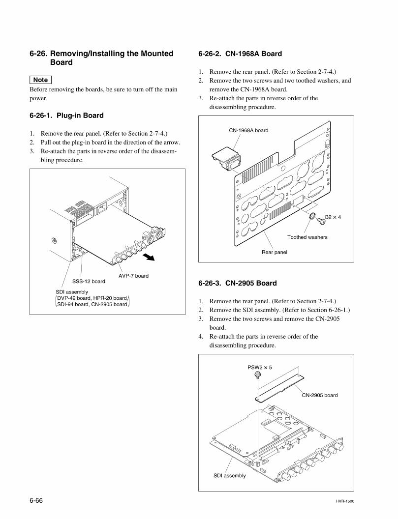
6-66 HVR-1500
6-26-2. CN-1968A Board
1. Remove the rear panel. (Refer to Section 2-7-4.)2. Remove the two screws and two toothed washers, and
remove the CN-1968A board.3. Re-attach the parts in reverse order of the
disassembling procedure.
6-26-3. CN-2905 Board
1. Remove the rear panel. (Refer to Section 2-7-4.)2. Remove the SDI assembly. (Refer to Section 6-26-1.)3. Remove the two screws and remove the CN-2905
board.4. Re-attach the parts in reverse order of the
disassembling procedure.
SDI assembly DVP-42 board, HPR-20 board, SDI-94 board, CN-2905 board
SSS-12 boardAVP-7 board
B2 x 4
CN-1968A board
Toothed washers
Rear panel
PSW2 x 5
CN-2905 board
SDI assembly
6-26. Removing/Installing the MountedBoard
nBefore removing the boards, be sure to turn off the mainpower.
6-26-1. Plug-in Board
1. Remove the rear panel. (Refer to Section 2-7-4.)2. Pull out the plug-in board in the direction of the arrow.3. Re-attach the parts in reverse order of the disassem-
bling procedure.
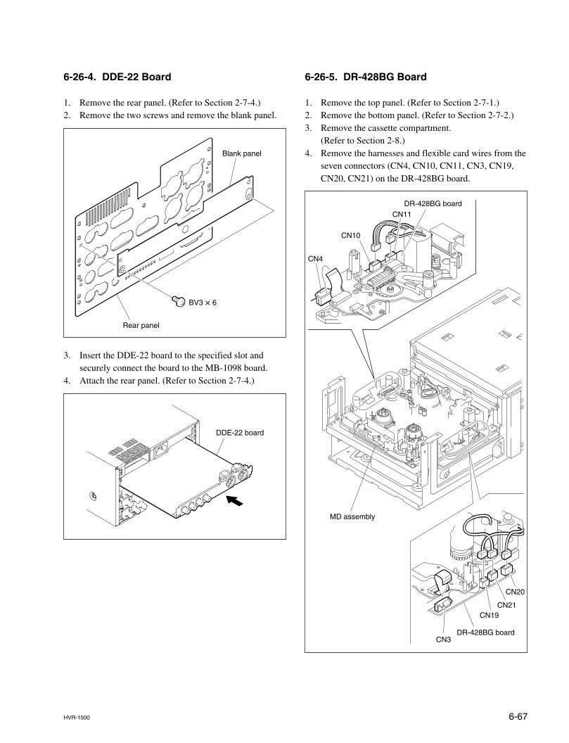
6-67HVR-1500
CN10
CN4
CN11DR-428BG board
CN19
DR-428BG boardCN3
CN21
CN20
MD assembly
6-26-4. DDE-22 Board
1. Remove the rear panel. (Refer to Section 2-7-4.)2. Remove the two screws and remove the blank panel.
3. Insert the DDE-22 board to the specified slot andsecurely connect the board to the MB-1098 board.
4. Attach the rear panel. (Refer to Section 2-7-4.)
BV3 x 6
Rear panel
Blank panel
DDE-22 board
6-26-5. DR-428BG Board
1. Remove the top panel. (Refer to Section 2-7-1.)2. Remove the bottom panel. (Refer to Section 2-7-2.)3. Remove the cassette compartment.
(Refer to Section 2-8.)4. Remove the harnesses and flexible card wires from the
seven connectors (CN4, CN10, CN11, CN3, CN19,CN20, CN21) on the DR-428BG board.
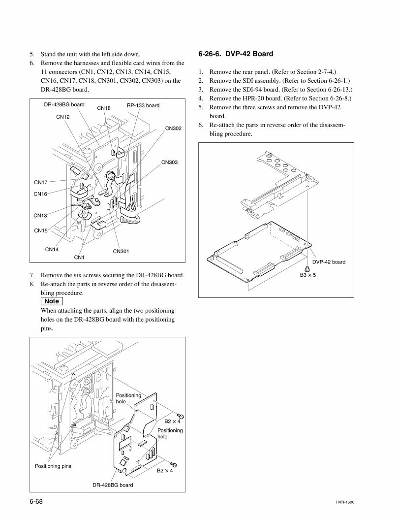
6-68 HVR-1500
CN1CN301
CN302
CN18
CN17
CN16
CN13
CN15
CN14
CN12
DR-428BG board RP-133 board
CN303
6-26-6. DVP-42 Board
1. Remove the rear panel. (Refer to Section 2-7-4.)2. Remove the SDI assembly. (Refer to Section 6-26-1.)3. Remove the SDI-94 board. (Refer to Section 6-26-13.)4. Remove the HPR-20 board. (Refer to Section 6-26-8.)5. Remove the three screws and remove the DVP-42
board.6. Re-attach the parts in reverse order of the disassem-
bling procedure.
5. Stand the unit with the left side down.6. Remove the harnesses and flexible card wires from the
11 connectors (CN1, CN12, CN13, CN14, CN15,CN16, CN17, CN18, CN301, CN302, CN303) on theDR-428BG board.
7. Remove the six screws securing the DR-428BG board.8. Re-attach the parts in reverse order of the disassem-
bling procedure.nWhen attaching the parts, align the two positioningholes on the DR-428BG board with the positioningpins.
B2 x 4
B2 x 4
DR-428BG board
Positioning hole
Positioning hole
Positioning pins
B3 x 5
DVP-42 board
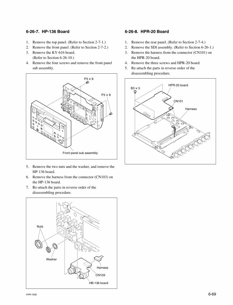
6-69HVR-1500
Front panel sub assembly
P3 x 8
P3 x 8
6-26-7. HP-136 Board
1. Remove the top panel. (Refer to Section 2-7-1.)2. Remove the front panel. (Refer to Section 2-7-2.)3. Remove the KY-616 board.
(Refer to Section 6-26-10.)4. Remove the four screws and remove the front panel
sub assembly.
5. Remove the two nuts and the washer, and remove theHP-136 board.
6. Remove the harness from the connector (CN103) onthe HP-136 board.
7. Re-attach the parts in reverse order of thedisassembling procedure.
HB-136 board
CN103
Nuts
Washer
Harness
6-26-8. HPR-20 Board
1. Remove the rear panel. (Refer to Section 2-7-4.)2. Remove the SDI assembly. (Refer to Section 6-26-1.)3. Remove the harness from the connector (CN101) on
the HPR-20 board.4. Remove the three screws and HPR-20 board.5. Re-attach the parts in reverse order of the
disassembling procedure.
HPR-20 board
Harness
CN101
B3 x 5
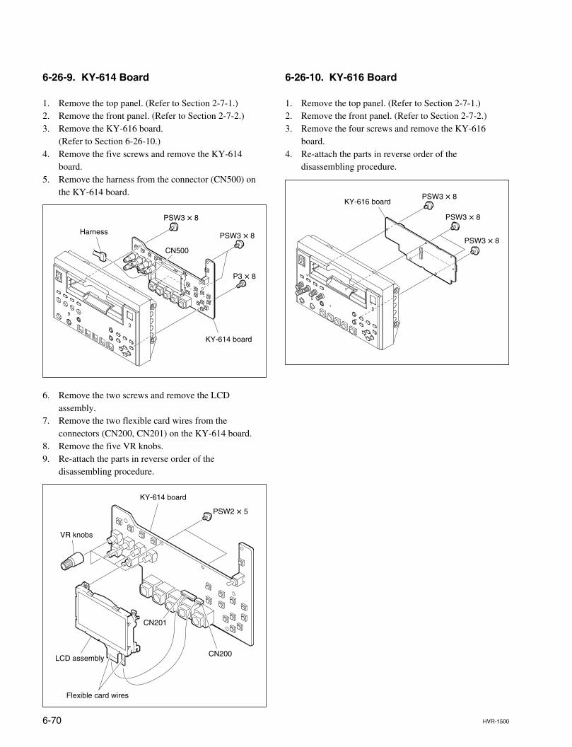
6-70 HVR-1500
6-26-10. KY-616 Board
1. Remove the top panel. (Refer to Section 2-7-1.)2. Remove the front panel. (Refer to Section 2-7-2.)3. Remove the four screws and remove the KY-616
board.4. Re-attach the parts in reverse order of the
disassembling procedure.
6-26-9. KY-614 Board
1. Remove the top panel. (Refer to Section 2-7-1.)2. Remove the front panel. (Refer to Section 2-7-2.)3. Remove the KY-616 board.
(Refer to Section 6-26-10.)4. Remove the five screws and remove the KY-614
board.5. Remove the harness from the connector (CN500) on
the KY-614 board.
6. Remove the two screws and remove the LCDassembly.
7. Remove the two flexible card wires from theconnectors (CN200, CN201) on the KY-614 board.
8. Remove the five VR knobs.9. Re-attach the parts in reverse order of the
disassembling procedure.
CN500
KY-614 board
Harness PSW3 x 8
PSW3 x 8
P3 x 8
CN201
CN200
KY-614 board
VR knobs
LCD assembly
Flexible card wires
PSW2 x 5
KY-616 boardPSW3 x 8
PSW3 x 8
PSW3 x 8
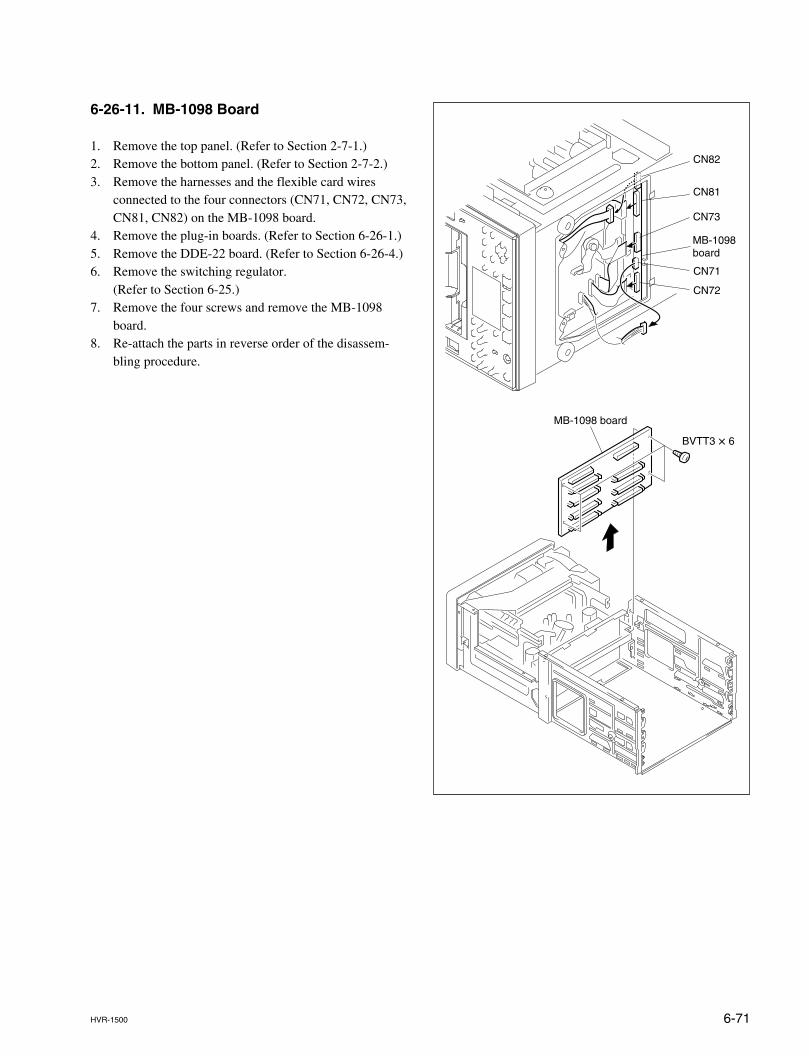
6-71HVR-1500
MB-1098 board
BVTT3 x 6
CN81
CN73
CN72
CN71
CN82
MB-1098 board
6-26-11. MB-1098 Board
1. Remove the top panel. (Refer to Section 2-7-1.)2. Remove the bottom panel. (Refer to Section 2-7-2.)3. Remove the harnesses and the flexible card wires
connected to the four connectors (CN71, CN72, CN73,CN81, CN82) on the MB-1098 board.
4. Remove the plug-in boards. (Refer to Section 6-26-1.)5. Remove the DDE-22 board. (Refer to Section 6-26-4.)6. Remove the switching regulator.
(Refer to Section 6-25.)7. Remove the four screws and remove the MB-1098
board.8. Re-attach the parts in reverse order of the disassem-
bling procedure.
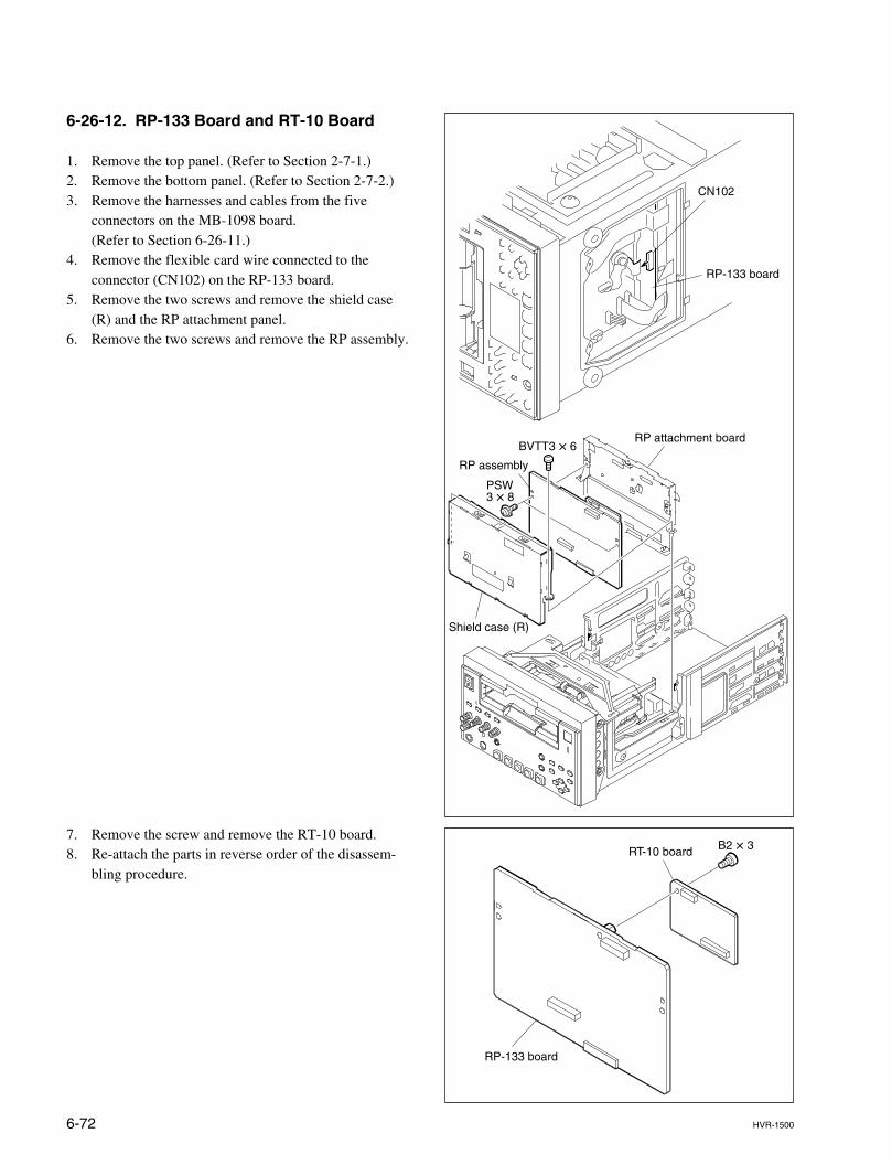
6-72 HVR-1500
RP assembly
Shield case (R)
RP attachment boardBVTT3 x 6
PSW3 x 8
CN102
RP-133 board
6-26-12. RP-133 Board and RT-10 Board
1. Remove the top panel. (Refer to Section 2-7-1.)2. Remove the bottom panel. (Refer to Section 2-7-2.)3. Remove the harnesses and cables from the five
connectors on the MB-1098 board.(Refer to Section 6-26-11.)
4. Remove the flexible card wire connected to theconnector (CN102) on the RP-133 board.
5. Remove the two screws and remove the shield case(R) and the RP attachment panel.
6. Remove the two screws and remove the RP assembly.
7. Remove the screw and remove the RT-10 board.8. Re-attach the parts in reverse order of the disassem-
bling procedure.
RP-133 board
RT-10 board B2 x 3
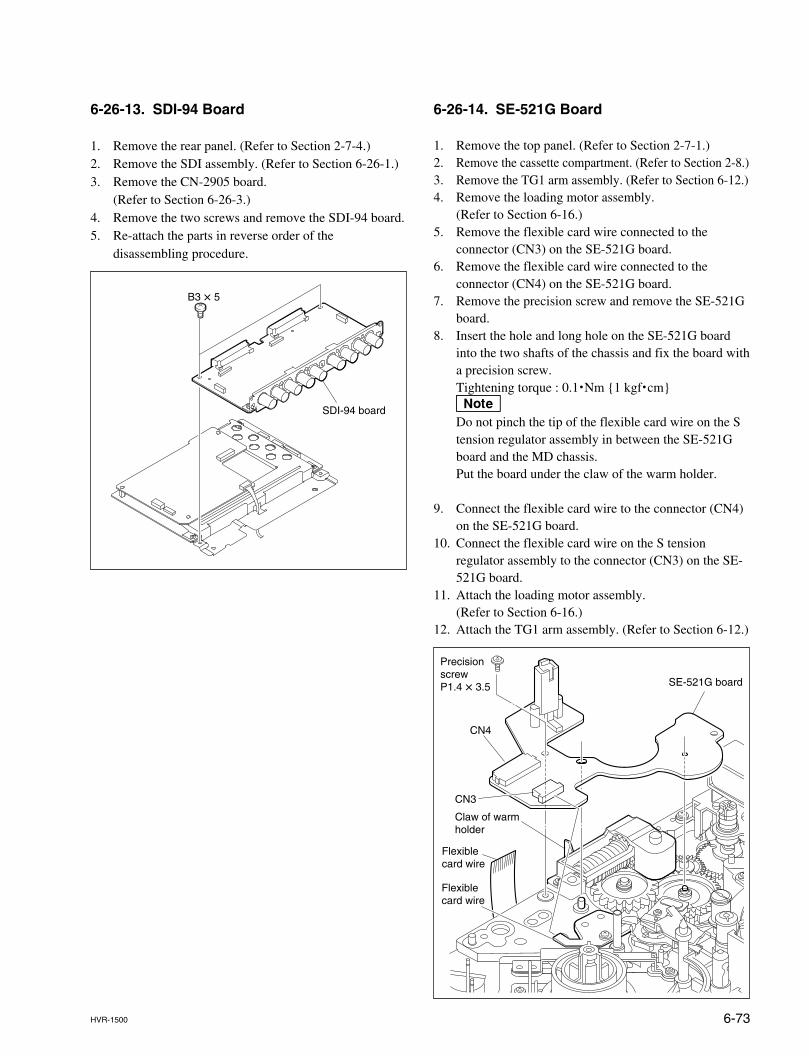
6-73HVR-1500
SE-521G board
CN4
CN3
Precision screw P1.4 x 3.5
Flexible card wire
Flexible card wire
Claw of warm holder
6-26-13. SDI-94 Board
1. Remove the rear panel. (Refer to Section 2-7-4.)2. Remove the SDI assembly. (Refer to Section 6-26-1.)3. Remove the CN-2905 board.
(Refer to Section 6-26-3.)4. Remove the two screws and remove the SDI-94 board.5. Re-attach the parts in reverse order of the
disassembling procedure.
B3 x 5
SDI-94 board
6-26-14. SE-521G Board
1. Remove the top panel. (Refer to Section 2-7-1.)2. Remove the cassette compartment. (Refer to Section 2-8.)3. Remove the TG1 arm assembly. (Refer to Section 6-12.)4. Remove the loading motor assembly.
(Refer to Section 6-16.)5. Remove the flexible card wire connected to the
connector (CN3) on the SE-521G board.6. Remove the flexible card wire connected to the
connector (CN4) on the SE-521G board.7. Remove the precision screw and remove the SE-521G
board.8. Insert the hole and long hole on the SE-521G board
into the two shafts of the chassis and fix the board witha precision screw.Tightening torque : 0.1.Nm {1 kgf.cm}nDo not pinch the tip of the flexible card wire on the Stension regulator assembly in between the SE-521Gboard and the MD chassis.Put the board under the claw of the warm holder.
9. Connect the flexible card wire to the connector (CN4)on the SE-521G board.
10. Connect the flexible card wire on the S tensionregulator assembly to the connector (CN3) on the SE-521G board.
11. Attach the loading motor assembly.(Refer to Section 6-16.)
12. Attach the TG1 arm assembly. (Refer to Section 6-12.)
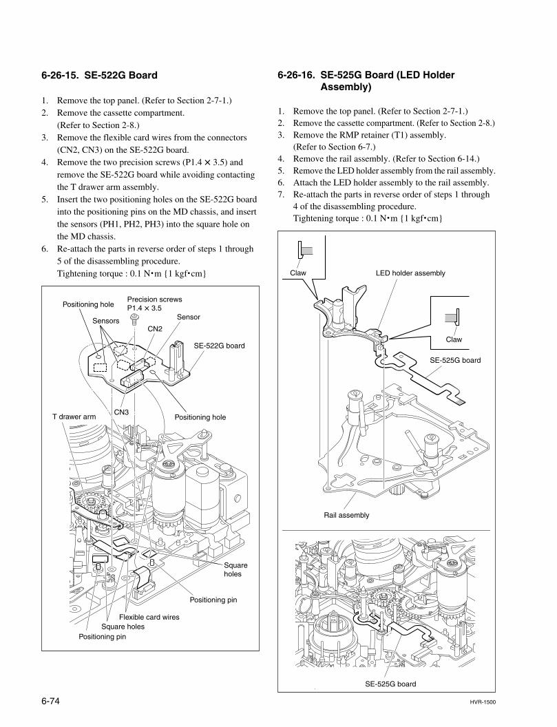
6-74 HVR-1500
Claw
Claw
LED holder assembly
Rail assembly
SE-525G board
SE-525G board
SE-522G board
Sensors
Positioning holeT drawer arm
Positioning pin
Square holes
Square holesPositioning pin
Positioning holePrecision screwsP1.4 x 3.5
Flexible card wires
CN2
CN3
Sensor
6-26-15. SE-522G Board
1. Remove the top panel. (Refer to Section 2-7-1.)2. Remove the cassette compartment.
(Refer to Section 2-8.)3. Remove the flexible card wires from the connectors
(CN2, CN3) on the SE-522G board.4. Remove the two precision screws (P1.4 x 3.5) and
remove the SE-522G board while avoiding contactingthe T drawer arm assembly.
5. Insert the two positioning holes on the SE-522G boardinto the positioning pins on the MD chassis, and insertthe sensors (PH1, PH2, PH3) into the square hole onthe MD chassis.
6. Re-attach the parts in reverse order of steps 1 through5 of the disassembling procedure.Tightening torque : 0.1 N.m {1 kgf.cm}
6-26-16. SE-525G Board (LED HolderAssembly)
1. Remove the top panel. (Refer to Section 2-7-1.)2. Remove the cassette compartment. (Refer to Section 2-8.)3. Remove the RMP retainer (T1) assembly.
(Refer to Section 6-7.)4. Remove the rail assembly. (Refer to Section 6-14.)5. Remove the LED holder assembly from the rail assembly.6. Attach the LED holder assembly to the rail assembly.7. Re-attach the parts in reverse order of steps 1 through
4 of the disassembling procedure.Tightening torque : 0.1 N.m {1 kgf.cm}
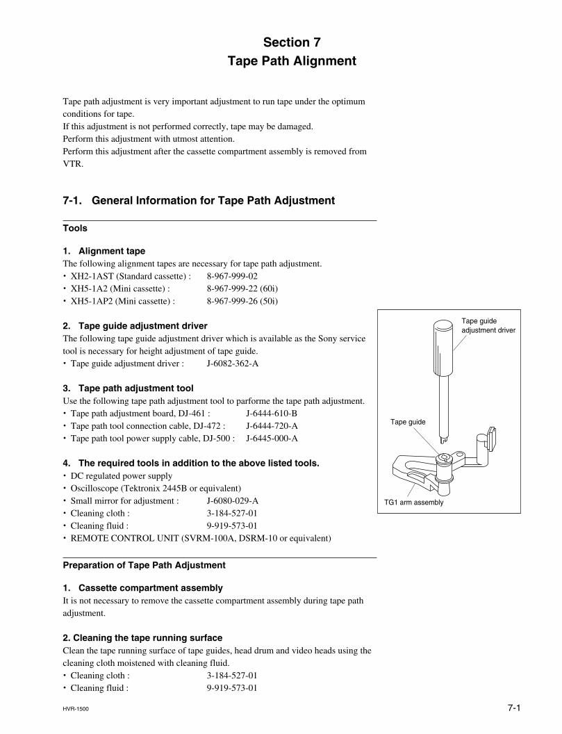
7-1HVR-1500
Tape path adjustment is very important adjustment to run tape under the optimumconditions for tape.If this adjustment is not performed correctly, tape may be damaged.Perform this adjustment with utmost attention.Perform this adjustment after the cassette compartment assembly is removed fromVTR.
7-1. General Information for Tape Path Adjustment
Tools
1. Alignment tapeThe following alignment tapes are necessary for tape path adjustment.. XH2-1AST (Standard cassette) : 8-967-999-02. XH5-1A2 (Mini cassette) : 8-967-999-22 (60i). XH5-1AP2 (Mini cassette) : 8-967-999-26 (50i)
2. Tape guide adjustment driverThe following tape guide adjustment driver which is available as the Sony servicetool is necessary for height adjustment of tape guide.. Tape guide adjustment driver : J-6082-362-A
3. Tape path adjustment toolUse the following tape path adjustment tool to parforme the tape path adjustment.. Tape path adjustment board, DJ-461 : J-6444-610-B. Tape path tool connection cable, DJ-472 : J-6444-720-A. Tape path tool power supply cable, DJ-500 : J-6445-000-A
4. The required tools in addition to the above listed tools.. DC regulated power supply. Oscilloscope (Tektronix 2445B or equivalent). Small mirror for adjustment : J-6080-029-A. Cleaning cloth : 3-184-527-01. Cleaning fluid : 9-919-573-01. REMOTE CONTROL UNIT (SVRM-100A, DSRM-10 or equivalent)
Preparation of Tape Path Adjustment
1. Cassette compartment assemblyIt is not necessary to remove the cassette compartment assembly during tape pathadjustment.
2. Cleaning the tape running surfaceClean the tape running surface of tape guides, head drum and video heads using thecleaning cloth moistened with cleaning fluid.. Cleaning cloth : 3-184-527-01. Cleaning fluid : 9-919-573-01
Section 7Tape Path Alignment
TG1 arm assembly
Tape guide adjustment driver
Tape guide
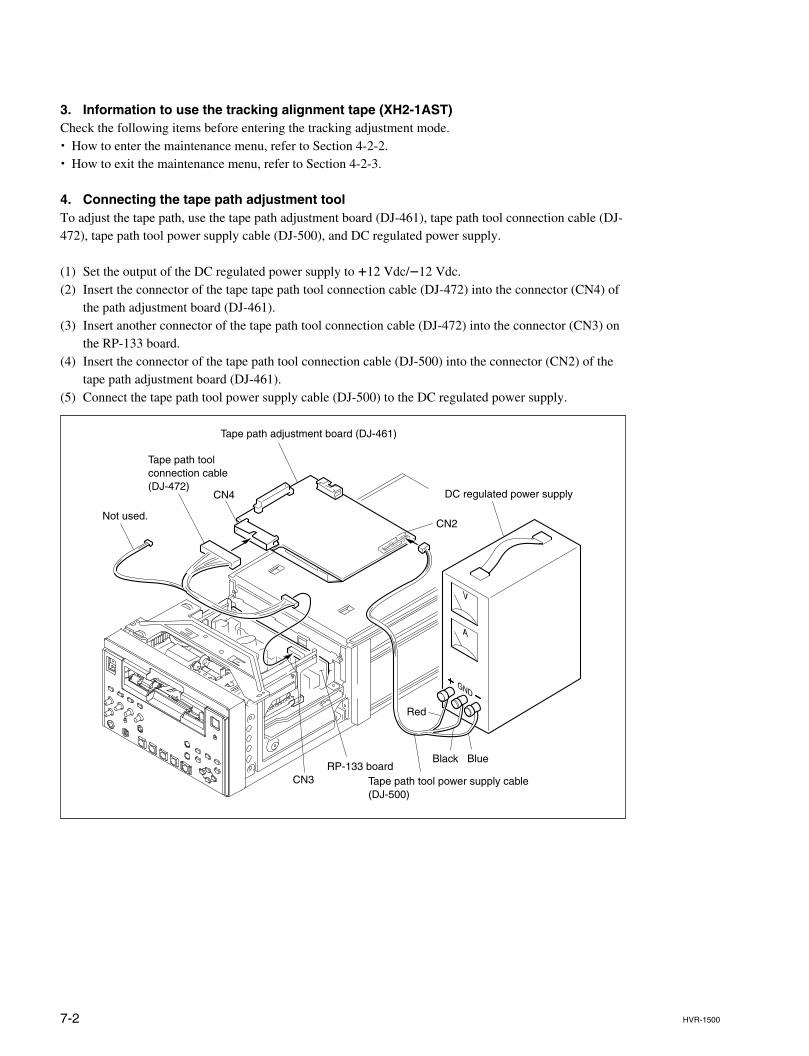
7-2 HVR-1500
3. Information to use the tracking alignment tape (XH2-1AST)Check the following items before entering the tracking adjustment mode.. How to enter the maintenance menu, refer to Section 4-2-2.. How to exit the maintenance menu, refer to Section 4-2-3.
4. Connecting the tape path adjustment toolTo adjust the tape path, use the tape path adjustment board (DJ-461), tape path tool connection cable (DJ-472), tape path tool power supply cable (DJ-500), and DC regulated power supply.
(1) Set the output of the DC regulated power supply to +12 Vdc/_12 Vdc.(2) Insert the connector of the tape tape path tool connection cable (DJ-472) into the connector (CN4) of
the path adjustment board (DJ-461).(3) Insert another connector of the tape path tool connection cable (DJ-472) into the connector (CN3) on
the RP-133 board.(4) Insert the connector of the tape path tool connection cable (DJ-500) into the connector (CN2) of the
tape path adjustment board (DJ-461).(5) Connect the tape path tool power supply cable (DJ-500) to the DC regulated power supply.
V
A
GND
Not used.
Tape path tool connection cable (DJ-472)
Tape path tool power supply cable(DJ-500)
Tape path adjustment board (DJ-461)
CN4
CN2
CN3
DC regulated power supply
RP-133 boardBlack Blue
Red
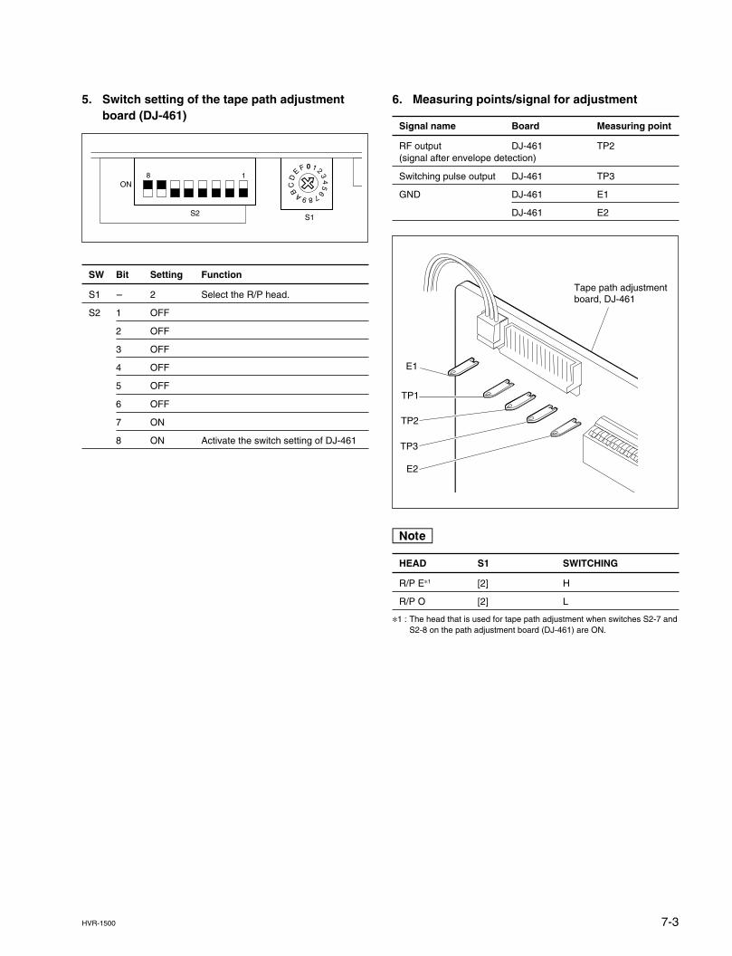
7-3HVR-1500
5. Switch setting of the tape path adjustmentboard (DJ-461)
SW Bit Setting Function
S1 _ 2 Select the R/P head.
S2 1 OFF
2 OFF
3 OFF
4 OFF
5 OFF
6 OFF
7 ON
8 ON Activate the switch setting of DJ-461
6. Measuring points/signal for adjustment
Signal name Board Measuring point
RF output DJ-461 TP2(signal after envelope detection)
Switching pulse output DJ-461 TP3
GND DJ-461 E1
DJ-461 E2
n
HEAD S1 SWITCHING
R/P E*1 [2] H
R/P O [2] L
*1 : The head that is used for tape path adjustment when switches S2-7 andS2-8 on the path adjustment board (DJ-461) are ON.
0 1 2 34
56789AB
CD
E
F
ON
S2 S1
8 1
TP1
E1
TP3
TP2
E2
Tape path adjustment board, DJ-461
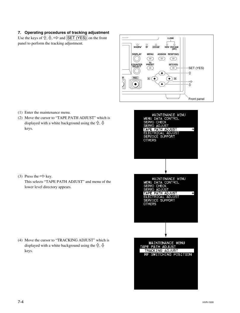
7-4 HVR-1500
7. Operating procedures of tracking adjustmentUse the keys of 9, 0, 8 and SET (YES) on the frontpanel to perform the tracking adjustment.
(1) Enter the maintenance menu.(2) Move the cursor to “TAPE PATH ADJUST” which is
displayed with a white background using the 9, 0keys.
(3) Press the 8 key.This selects “TAPE PATH ADJUST” and menu of thelower level directory appears.
(4) Move the cursor to “TRACKING ADJUST” which isdisplayed with a white background using the 9, 0keys.
SET (YES)
Front panel
9
08
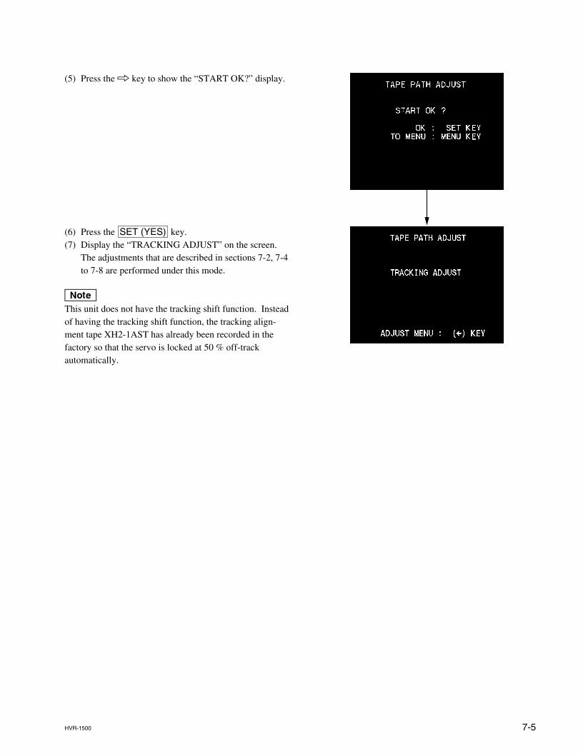
7-5HVR-1500
(5) Press the 8 key to show the “START OK?” display.
(6) Press the SET (YES) key.(7) Display the “TRACKING ADJUST” on the screen.
The adjustments that are described in sections 7-2, 7-4to 7-8 are performed under this mode.
nThis unit does not have the tracking shift function. Insteadof having the tracking shift function, the tracking align-ment tape XH2-1AST has already been recorded in thefactory so that the servo is locked at 50 % off-trackautomatically.
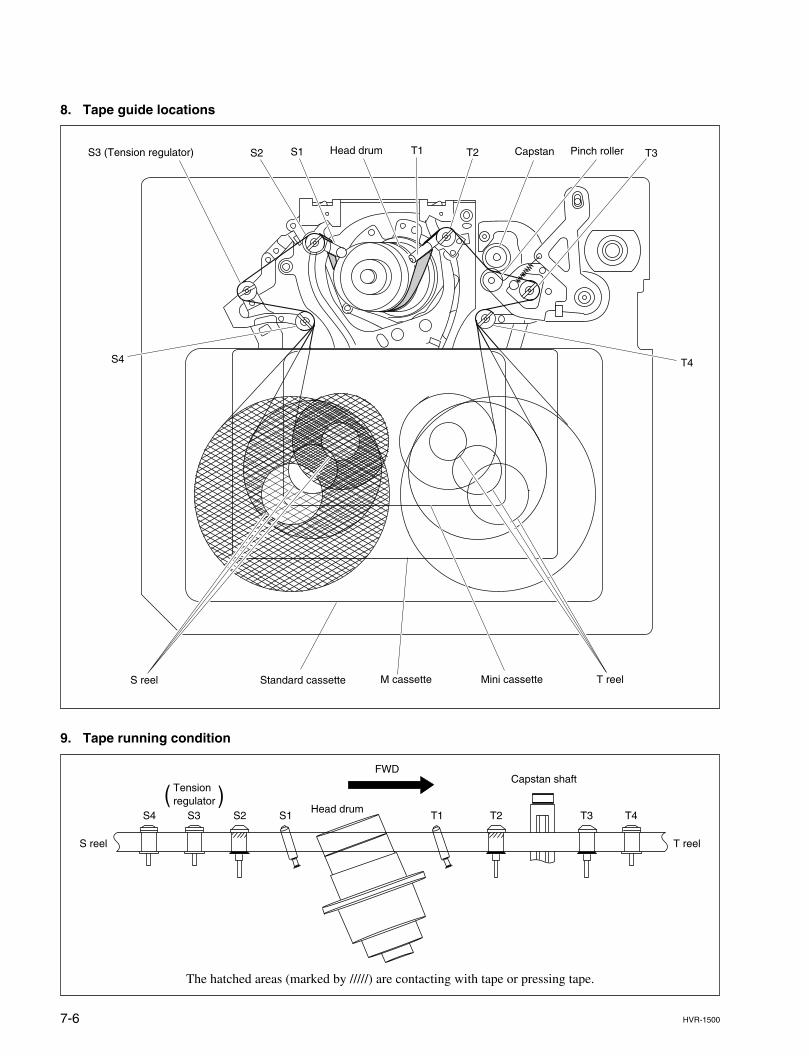
7-6 HVR-1500
The hatched areas (marked by /////) are contacting with tape or pressing tape.
8. Tape guide locations
9. Tape running condition
S1S2S3 (Tension regulator) T1 T2
T4
Head drum
S4
Capstan Pinch roller
T reelMini cassetteM cassetteStandard cassetteS reel
T3
FWD
T1 T2 T3 T4S1S2S3S4
( )
S reel
Tension regulator
Head drum
Capstan shaft
T reel
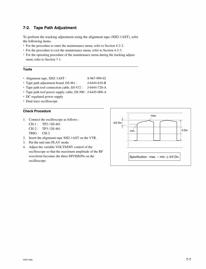
7-7HVR-1500
7-2. Tape Path Adjustment
To perform the tracking adjustment using the alignment tape (XH2-1AST), referthe following items.. For the procedure to enter the maintenance menu, refer to Section 4-2-2.. For the procedure to exit the maintenance menu, refer to Section 4-2-3.. For the operating procedure of the maintenance menu during the tracking adjust-
ment, refer to Section 7-1.
Tools
. Alignment tape, XH2-1AST : 8-967-999-02
. Tape path adjustment board, DJ-461 : J-6444-610-B
. Tape path tool connection cable, DJ-472 : J-6444-720-A
. Tape path tool power supply cable, DJ-500 : J-6445-000-A
. DC regulated power supply
. Dual trace oscilloscope
Check Procedure
1. Connect the oscilloscope as follows :CH-1 : TP2 / DJ-461CH-2 : TP3 / DJ-461TRIG : CH-2
2. Insert the alignment tape XH2-1AST on the VTR.3. Put the unit into PLAY mode.4. Adjust the variable VOLTS/DIV control of the
oscilloscope so that the maximum amplitude of the RFwaveform becomes the three DIVISIONs on theoscilloscope.
4/5 Div
max.
min. 3 Div
Specification : max. _ min. < 4/5 Div
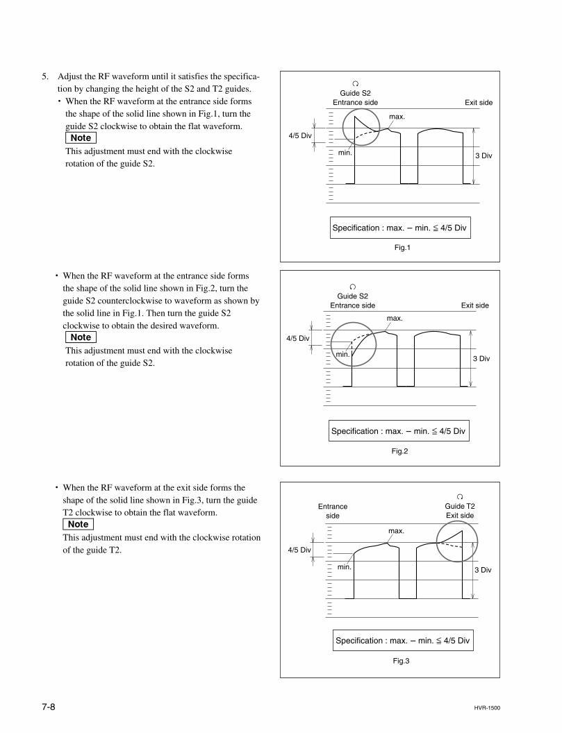
7-8 HVR-1500
5. Adjust the RF waveform until it satisfies the specifica-tion by changing the height of the S2 and T2 guides.. When the RF waveform at the entrance side forms
the shape of the solid line shown in Fig.1, turn theguide S2 clockwise to obtain the flat waveform.nThis adjustment must end with the clockwiserotation of the guide S2.
. When the RF waveform at the entrance side formsthe shape of the solid line shown in Fig.2, turn theguide S2 counterclockwise to waveform as shown bythe solid line in Fig.1. Then turn the guide S2clockwise to obtain the desired waveform.nThis adjustment must end with the clockwiserotation of the guide S2.
. When the RF waveform at the exit side forms theshape of the solid line shown in Fig.3, turn the guideT2 clockwise to obtain the flat waveform.nThis adjustment must end with the clockwise rotationof the guide T2.
max.
3 Divmin.
4/5 Div
Fig.2
Specification : max. _ min. < 4/5 Div
3Guide S2
Entrance side Exit side
max.
3 Divmin.
4/5 Div
Fig.3
2Guide T2Exit side
Entranceside
Specification : max. _ min. < 4/5 Div
max.
3 Divmin.
4/5 Div
Fig.1
Specification : max. _ min. < 4/5 Div
2Guide S2
Entrance side Exit side
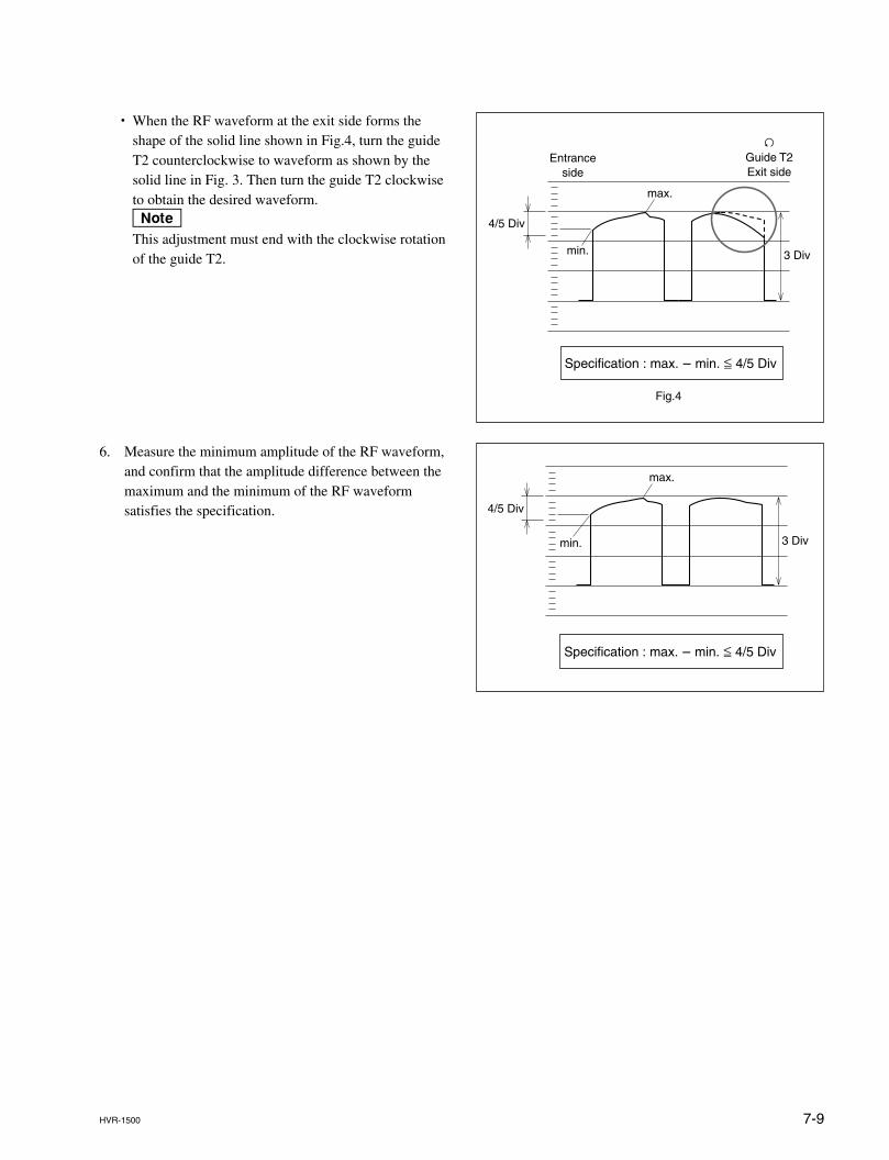
7-9HVR-1500
. When the RF waveform at the exit side forms theshape of the solid line shown in Fig.4, turn the guideT2 counterclockwise to waveform as shown by thesolid line in Fig. 3. Then turn the guide T2 clockwiseto obtain the desired waveform.nThis adjustment must end with the clockwise rotationof the guide T2.
6. Measure the minimum amplitude of the RF waveform,and confirm that the amplitude difference between themaximum and the minimum of the RF waveformsatisfies the specification.
max.
3 Divmin.
4/5 Div
Fig.4
Specification : max. _ min. < 4/5 Div
3Guide T2Exit side
Entranceside
4/5 Div
max.
min. 3 Div
Specification : max. _ min. < 4/5 Div
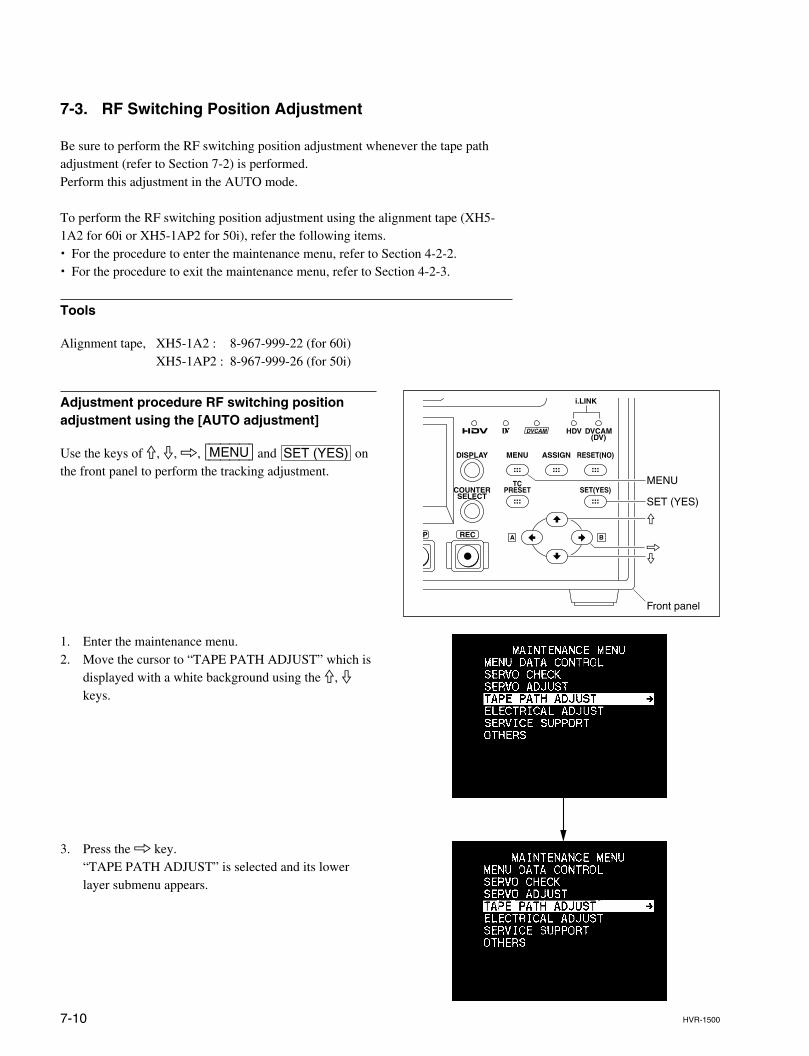
7-10 HVR-1500
7-3. RF Switching Position Adjustment
Be sure to perform the RF switching position adjustment whenever the tape pathadjustment (refer to Section 7-2) is performed.Perform this adjustment in the AUTO mode.
To perform the RF switching position adjustment using the alignment tape (XH5-1A2 for 60i or XH5-1AP2 for 50i), refer the following items.. For the procedure to enter the maintenance menu, refer to Section 4-2-2.. For the procedure to exit the maintenance menu, refer to Section 4-2-3.
Tools
Alignment tape, XH5-1A2 : 8-967-999-22 (for 60i)XH5-1AP2 : 8-967-999-26 (for 50i)
Adjustment procedure RF switching positionadjustment using the [AUTO adjustment]
Use the keys of 9, 0, 8, [MENU] and SET (YES) onthe front panel to perform the tracking adjustment.
1. Enter the maintenance menu.2. Move the cursor to “TAPE PATH ADJUST” which is
displayed with a white background using the 9, 0keys.
3. Press the 8 key.“TAPE PATH ADJUST” is selected and its lowerlayer submenu appears.
SET (YES)
MENU
Front panel
9
08
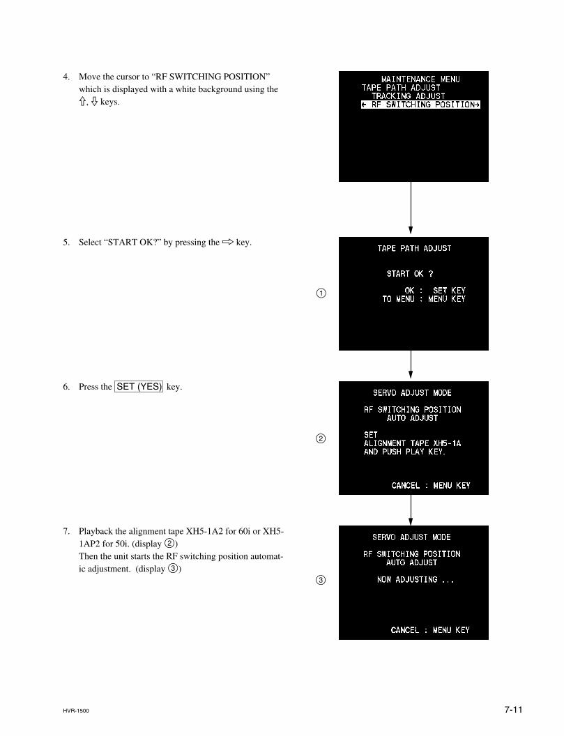
7-11HVR-1500
4. Move the cursor to “RF SWITCHING POSITION”which is displayed with a white background using the9, 0 keys.
1
2
3
5. Select “START OK?” by pressing the 8 key.
6. Press the SET (YES) key.
7. Playback the alignment tape XH5-1A2 for 60i or XH5-1AP2 for 50i. (display 2)Then the unit starts the RF switching position automat-ic adjustment. (display 3)
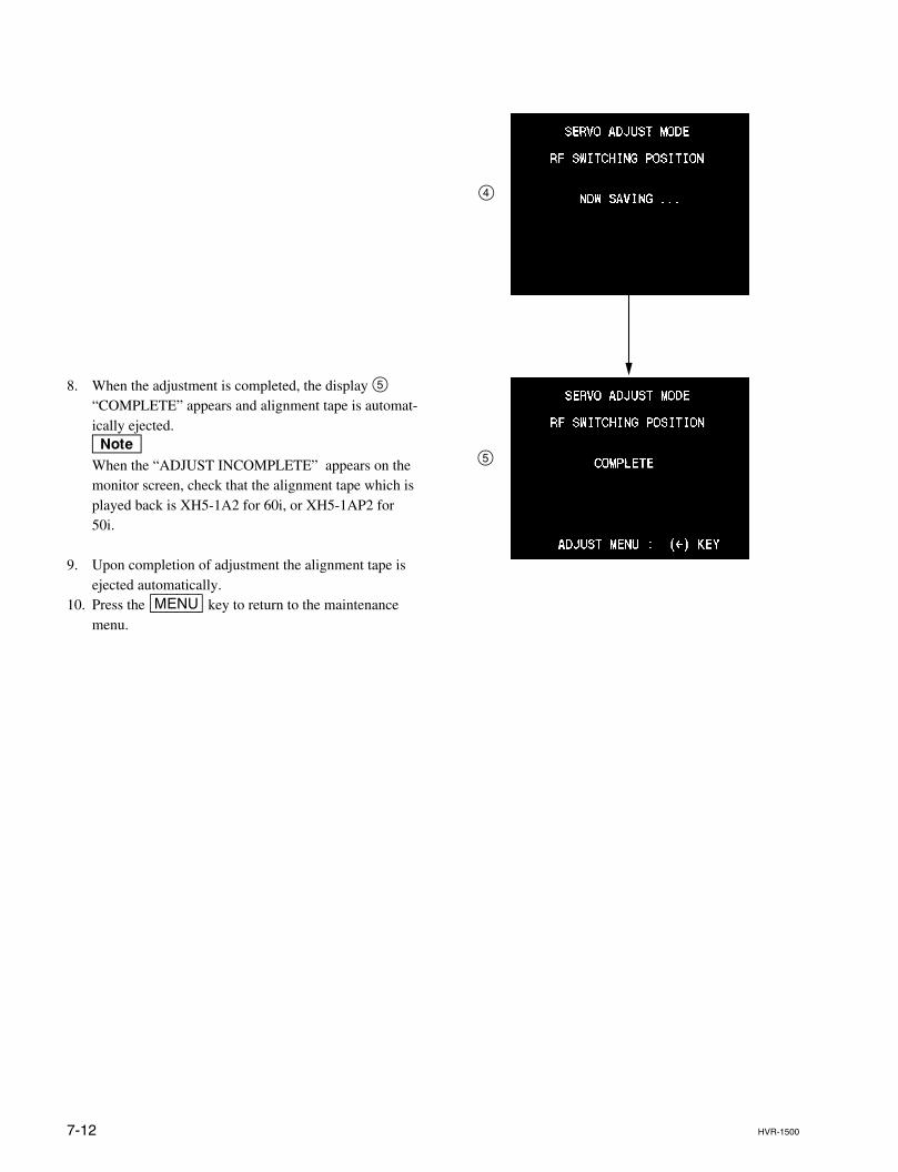
7-12 HVR-1500
8. When the adjustment is completed, the display 5“COMPLETE” appears and alignment tape is automat-ically ejected.nWhen the “ADJUST INCOMPLETE” appears on themonitor screen, check that the alignment tape which isplayed back is XH5-1A2 for 60i, or XH5-1AP2 for50i.
9. Upon completion of adjustment the alignment tape isejected automatically.
10. Press the [MENU] key to return to the maintenancemenu.
4
5
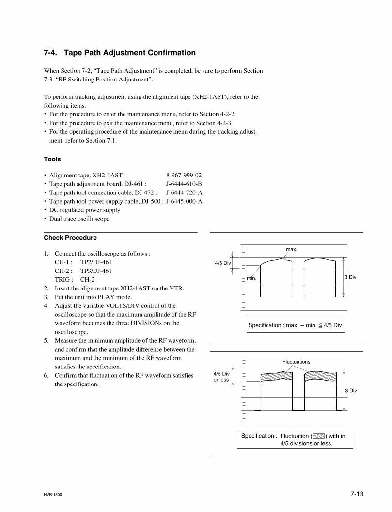
7-13HVR-1500
7-4. Tape Path Adjustment Confirmation
When Section 7-2, “Tape Path Adjustment” is completed, be sure to perform Section7-3. “RF Switching Position Adjustment”.
To perform tracking adjustment using the alignment tape (XH2-1AST), refer to thefollowing items.. For the procedure to enter the maintenance menu, refer to Section 4-2-2.. For the procedure to exit the maintenance menu, refer to Section 4-2-3.. For the operating procedure of the maintenance menu during the tracking adjust-
ment, refer to Section 7-1.
Tools
. Alignment tape, XH2-1AST : 8-967-999-02
. Tape path adjustment board, DJ-461 : J-6444-610-B
. Tape path tool connection cable, DJ-472 : J-6444-720-A
. Tape path tool power supply cable, DJ-500 : J-6445-000-A
. DC regulated power supply
. Dual trace oscilloscope
Check Procedure
1. Connect the oscilloscope as follows :CH-1 : TP2/DJ-461CH-2 : TP3/DJ-461TRIG : CH-2
2. Insert the alignment tape XH2-1AST on the VTR.3. Put the unit into PLAY mode.4 Adjust the variable VOLTS/DIV control of the
oscilloscope so that the maximum amplitude of the RFwaveform becomes the three DIVISIONs on theoscilloscope.
5. Measure the minimum amplitude of the RF waveform,and confirm that the amplitude difference between themaximum and the minimum of the RF waveformsatisfies the specification.
6. Confirm that fluctuation of the RF waveform satisfiesthe specification.
4/5 Div
max.
min. 3 Div
Specification : max. _ min. < 4/5 Div
3 Div
Fluctuations
Specification :
4/5 Divor less
Fluctuation ( ) with in 4/5 divisions or less.
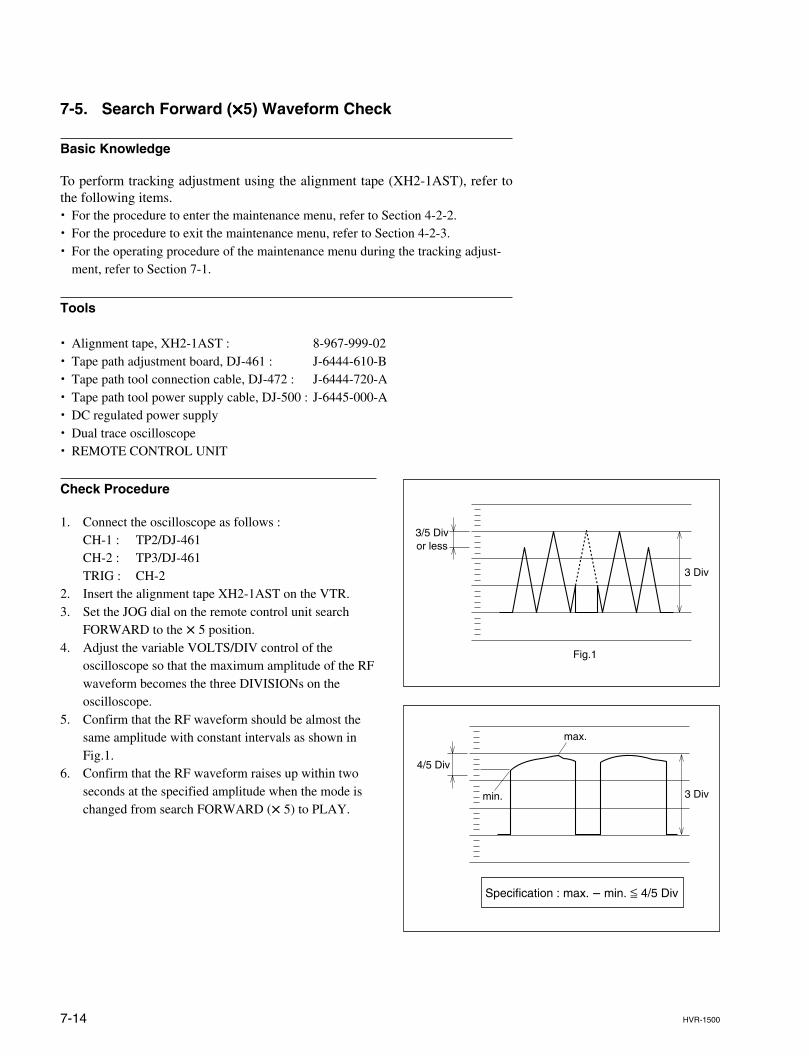
7-14 HVR-1500
7-5. Search Forward (xxxxx5) Waveform Check
Basic Knowledge
To perform tracking adjustment using the alignment tape (XH2-1AST), refer tothe following items.. For the procedure to enter the maintenance menu, refer to Section 4-2-2.. For the procedure to exit the maintenance menu, refer to Section 4-2-3.. For the operating procedure of the maintenance menu during the tracking adjust-
ment, refer to Section 7-1.
Tools
. Alignment tape, XH2-1AST : 8-967-999-02
. Tape path adjustment board, DJ-461 : J-6444-610-B
. Tape path tool connection cable, DJ-472 : J-6444-720-A
. Tape path tool power supply cable, DJ-500 : J-6445-000-A
. DC regulated power supply
. Dual trace oscilloscope
. REMOTE CONTROL UNIT
Check Procedure
1. Connect the oscilloscope as follows :CH-1 : TP2/DJ-461CH-2 : TP3/DJ-461TRIG : CH-2
2. Insert the alignment tape XH2-1AST on the VTR.3. Set the JOG dial on the remote control unit search
FORWARD to the x 5 position.4. Adjust the variable VOLTS/DIV control of the
oscilloscope so that the maximum amplitude of the RFwaveform becomes the three DIVISIONs on theoscilloscope.
5. Confirm that the RF waveform should be almost thesame amplitude with constant intervals as shown inFig.1.
6. Confirm that the RF waveform raises up within twoseconds at the specified amplitude when the mode ischanged from search FORWARD (x 5) to PLAY.
3 Div
Fig.1
3/5 Divor less
4/5 Div
max.
min. 3 Div
Specification : max. _ min. < 4/5 Div
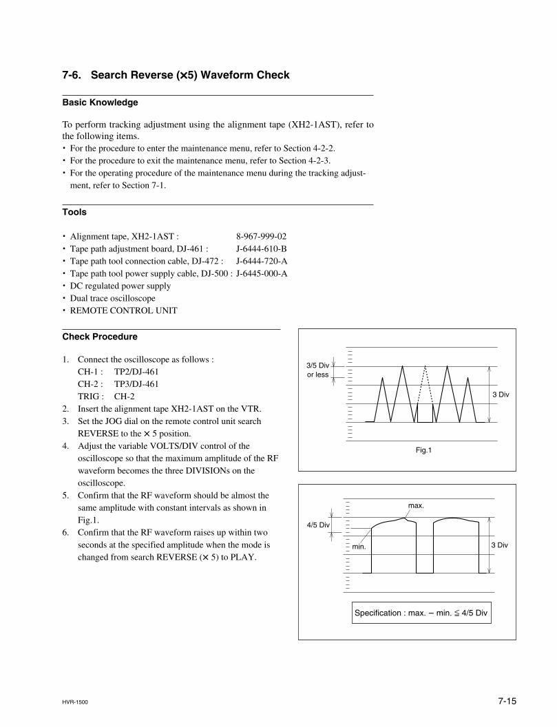
7-15HVR-1500
7-6. Search Reverse (xxxxx5) Waveform Check
Basic Knowledge
To perform tracking adjustment using the alignment tape (XH2-1AST), refer tothe following items.. For the procedure to enter the maintenance menu, refer to Section 4-2-2.. For the procedure to exit the maintenance menu, refer to Section 4-2-3.. For the operating procedure of the maintenance menu during the tracking adjust-
ment, refer to Section 7-1.
Tools
. Alignment tape, XH2-1AST : 8-967-999-02
. Tape path adjustment board, DJ-461 : J-6444-610-B
. Tape path tool connection cable, DJ-472 : J-6444-720-A
. Tape path tool power supply cable, DJ-500 : J-6445-000-A
. DC regulated power supply
. Dual trace oscilloscope
. REMOTE CONTROL UNIT
Check Procedure
1. Connect the oscilloscope as follows :CH-1 : TP2/DJ-461CH-2 : TP3/DJ-461TRIG : CH-2
2. Insert the alignment tape XH2-1AST on the VTR.3. Set the JOG dial on the remote control unit search
REVERSE to the x 5 position.4. Adjust the variable VOLTS/DIV control of the
oscilloscope so that the maximum amplitude of the RFwaveform becomes the three DIVISIONs on theoscilloscope.
5. Confirm that the RF waveform should be almost thesame amplitude with constant intervals as shown inFig.1.
6. Confirm that the RF waveform raises up within twoseconds at the specified amplitude when the mode ischanged from search REVERSE (x 5) to PLAY.
3 Div
Fig.1
3/5 Divor less
4/5 Div
max.
min. 3 Div
Specification : max. _ min. < 4/5 Div
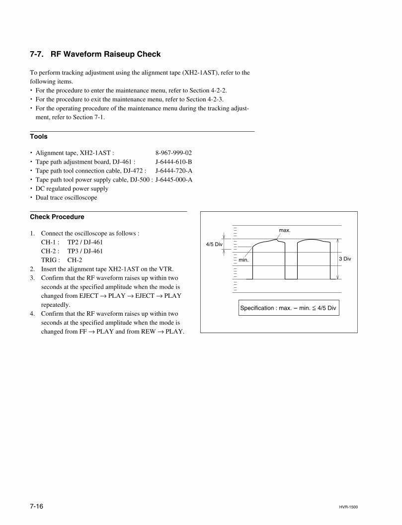
7-16 HVR-1500
7-7. RF Waveform Raiseup Check
To perform tracking adjustment using the alignment tape (XH2-1AST), refer to thefollowing items.. For the procedure to enter the maintenance menu, refer to Section 4-2-2.. For the procedure to exit the maintenance menu, refer to Section 4-2-3.. For the operating procedure of the maintenance menu during the tracking adjust-
ment, refer to Section 7-1.
Tools
. Alignment tape, XH2-1AST : 8-967-999-02
. Tape path adjustment board, DJ-461 : J-6444-610-B
. Tape path tool connection cable, DJ-472 : J-6444-720-A
. Tape path tool power supply cable, DJ-500 : J-6445-000-A
. DC regulated power supply
. Dual trace oscilloscope
4/5 Div
max.
min. 3 Div
Specification : max. _ min. < 4/5 Div
Check Procedure
1. Connect the oscilloscope as follows :CH-1 : TP2 / DJ-461CH-2 : TP3 / DJ-461TRIG : CH-2
2. Insert the alignment tape XH2-1AST on the VTR.3. Confirm that the RF waveform raises up within two
seconds at the specified amplitude when the mode ischanged from EJECT → PLAY → EJECT → PLAYrepeatedly.
4. Confirm that the RF waveform raises up within twoseconds at the specified amplitude when the mode ischanged from FF → PLAY and from REW → PLAY.
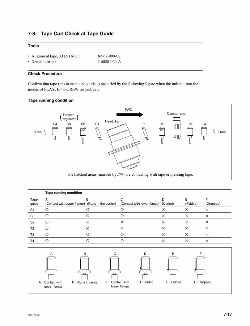
7-17HVR-1500
The hatched areas (marked by /////) are contacting with tape or pressing tape.
7-8. Tape Curl Check at Tape Guide
Tools
. Alignment tape, XH2-1AST : 8-967-999-02
. Dental mirror : J-6080-029-A
Check Procedure
Confirm that tape runs at each tape guide as specified by the following figure when the unit put into themodes of PLAY, FF and REW respectively.
Tape running condition
FWD
T1 T2 T3 T4S1S2S3S4
( )
S reel
Tension regulator
Head drum
Capstan shaft
T reel
Tape running condition
Tape A B C D E Fguide (Contact with upper flange) (Runs in the center) (Contact with lower flange) (Curled) (Folded) (Dropped)
S4 O O O X X X
S3 O O O X X X
S2 O X X X X X
T2 O X X X X X
T3 O O O X X X
T4 O O O X X X
A B C D E F
A : B : C : D : Curled E : Folded F : DroppedContact withupper flange
Runs in center Contact withlower flange

8-1HVR-1500
Section 8Electrical Alignment
8-1. Electrical Alignment Overview
8-1-1. Precautions
. Some items in this section require to perform adjustment in both the 59.94 Hz mode and the 50 Hzmode. Switch the mode and adjust as directed.
. Be sure to adjust each block in order unless any instructions are provided.
. Do not contact with adjusting part when other than required.
. For details on the maintenance mode, refer to Section 4.
. Before beginning adjustment, it is recommended to make a copy of setup conditions. If customerconditions are noted, the settings can be returned easily to its customer condition after finishing adjust-ment.- Setting of switches on front panel.- Setup menu (Refer to Section 4-3-1.)
8-1-2. Outline of Electrical Alignment
In Section 8 explains the all electrical adjustment to each block.
Block Reference Contents Object of adjustment
Audio Section 8-2 Audio output level adjustment, Audio EE level adjustment AVP-7, DDE-22
Video Section 8-3 Internal clock frequency adjustment, Video signal output level adjustment AVP-7, DDE-22Video signal REC level adjustment
SDI Section 8-4 SDI free-running adjustment SDI-94
LCD Section 8-5 LCD adjustment KY-614, KY-616
8-1-3. Equipment and Fixture
Equipment and Fixture Model name Remark
Oscilloscope Tektronix TDS460A or equivalents
Video signal generator Tektronix TSG-130A or equivalents For 59.94 Hz mode
Tektronix TSG-131A or equivalents For 50 Hz mode
Waveform monitor Tektronix 1750A or equivalents
Audio level meter Agilent technologies HP3400A or equivalents
Frequency counter Advantest TR5821 or equivalents
Extension board DJ-516
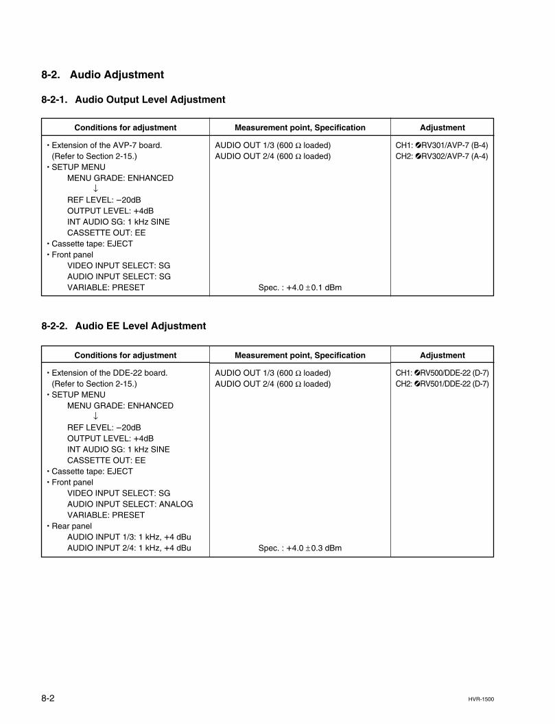
8-2 HVR-1500
8-2-2. Audio EE Level Adjustment
Measurement point, Specification
AUDIO OUT 1/3 (600 Z loaded)AUDIO OUT 2/4 (600 Z loaded)
Spec. : +4.0 ±0.1 dBm
Conditions for adjustment
. Extension of the AVP-7 board.(Refer to Section 2-15.)
. SETUP MENUMENU GRADE: ENHANCED
↓REF LEVEL: _20dBOUTPUT LEVEL: +4dBINT AUDIO SG: 1 kHz SINECASSETTE OUT: EE
. Cassette tape: EJECT
. Front panelVIDEO INPUT SELECT: SGAUDIO INPUT SELECT: SGVARIABLE: PRESET
8-2. Audio Adjustment
8-2-1. Audio Output Level Adjustment
Adjustment
CH1: 1RV301/AVP-7 (B-4)CH2: 1RV302/AVP-7 (A-4)
Measurement point, Specification
AUDIO OUT 1/3 (600 Z loaded)AUDIO OUT 2/4 (600 Z loaded)
Spec. : +4.0 ±0.3 dBm
Conditions for adjustment
. Extension of the DDE-22 board.(Refer to Section 2-15.)
. SETUP MENUMENU GRADE: ENHANCED
↓REF LEVEL: _20dBOUTPUT LEVEL: +4dBINT AUDIO SG: 1 kHz SINECASSETTE OUT: EE
. Cassette tape: EJECT
. Front panelVIDEO INPUT SELECT: SGAUDIO INPUT SELECT: ANALOGVARIABLE: PRESET
. Rear panelAUDIO INPUT 1/3: 1 kHz, +4 dBuAUDIO INPUT 2/4: 1 kHz, +4 dBu
Adjustment
CH1: 1RV500/DDE-22 (D-7)CH2: 1RV501/DDE-22 (D-7)
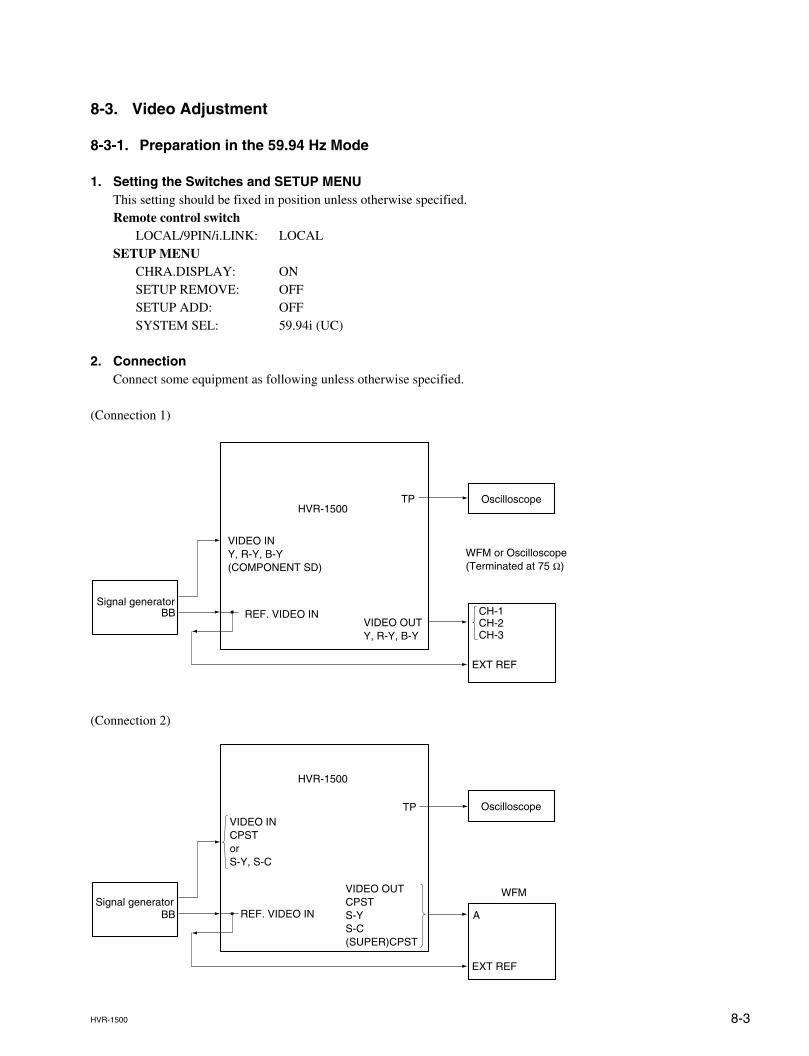
8-3HVR-1500
8-3. Video Adjustment
8-3-1. Preparation in the 59.94 Hz Mode
1. Setting the Switches and SETUP MENUThis setting should be fixed in position unless otherwise specified.Remote control switch
LOCAL/9PIN/i.LINK: LOCALSETUP MENU
CHRA.DISPLAY: ONSETUP REMOVE: OFFSETUP ADD: OFFSYSTEM SEL: 59.94i (UC)
2. ConnectionConnect some equipment as following unless otherwise specified.
(Connection 1)
(Connection 2)
Oscilloscope
EXT REF
CH-1CH-2CH-3
WFM or Oscilloscope(Terminated at 75 Z)
VIDEO OUTY, R-Y, B-Y
Signal generatorBB
TP
REF. VIDEO IN
HVR-1500
VIDEO INY, R-Y, B-Y(COMPONENT SD)
Oscilloscope
A
EXT REF
WFMVIDEO OUT CPSTS-YS-C(SUPER)CPST
Signal generatorBB
TP
REF. VIDEO IN
HVR-1500
VIDEO INCPSTorS-Y, S-C
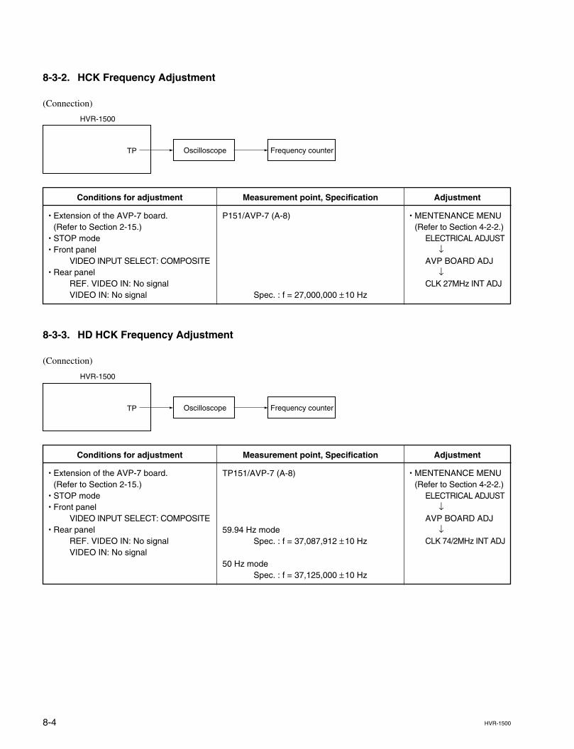
8-4 HVR-1500
8-3-2. HCK Frequency Adjustment
(Connection)
Oscilloscope Frequency counterTP
HVR-1500
Measurement point, Specification
P151/AVP-7 (A-8)
Spec. : f = 27,000,000 ±10 Hz
Conditions for adjustment
. Extension of the AVP-7 board.(Refer to Section 2-15.)
. STOP mode
. Front panelVIDEO INPUT SELECT: COMPOSITE
. Rear panelREF. VIDEO IN: No signalVIDEO IN: No signal
Adjustment
. MENTENANCE MENU(Refer to Section 4-2-2.)
ELECTRICAL ADJUST↓
AVP BOARD ADJ↓
CLK 27MHz INT ADJ
8-3-3. HD HCK Frequency Adjustment
(Connection)
TP
HVR-1500
Oscilloscope Frequency counter
Measurement point, Specification
TP151/AVP-7 (A-8)
59.94 Hz modeSpec. : f = 37,087,912 ±10 Hz
50 Hz modeSpec. : f = 37,125,000 ±10 Hz
Conditions for adjustment
. Extension of the AVP-7 board.(Refer to Section 2-15.)
. STOP mode
. Front panelVIDEO INPUT SELECT: COMPOSITE
. Rear panelREF. VIDEO IN: No signalVIDEO IN: No signal
Adjustment
. MENTENANCE MENU(Refer to Section 4-2-2.)
ELECTRICAL ADJUST↓
AVP BOARD ADJ↓
CLK 74/2MHz INT ADJ
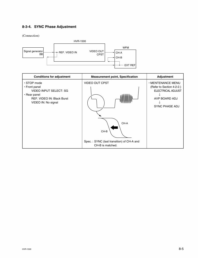
8-5HVR-1500
8-3-4. SYNC Phase Adjustment
(Connection)
CH-A
CH-B
EXT REF
WFM
HVR-1500
VIDEO OUTCPST
Signal generatorBB
REF. VIDEO IN
Measurement point, Specification
VIDEO OUT CPST
Spec. : SYNC (last transition) of CH-A andCH-B is matched.
Conditions for adjustment
. STOP mode
. Front panelVIDEO INPUT SELECT: SG
. Rear panelREF. VIDEO IN: Black BurstVIDEO IN: No signal
Adjustment
. MENTENANCE MENU(Refer to Section 4-2-2.)
ELECTRICAL ADJUST↓
AVP BOARD ADJ↓
SYNC PHASE ADJ
CH-A
CH-B
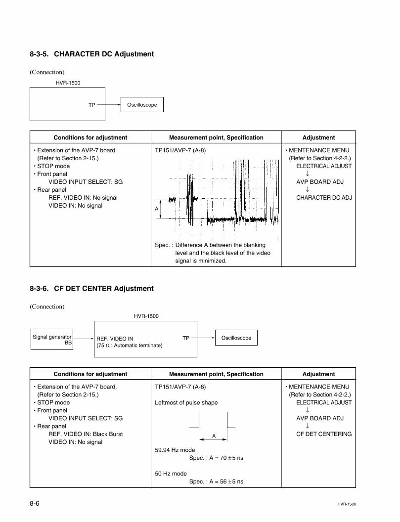
8-6 HVR-1500
8-3-5. CHARACTER DC Adjustment
(Connection)
TP
HVR-1500
Oscilloscope
Measurement point, Specification
TP151/AVP-7 (A-8)
Spec. : Difference A between the blankinglevel and the black level of the videosignal is minimized.
Conditions for adjustment
. Extension of the AVP-7 board.(Refer to Section 2-15.)
. STOP mode
. Front panelVIDEO INPUT SELECT: SG
. Rear panelREF. VIDEO IN: No signalVIDEO IN: No signal
Adjustment
. MENTENANCE MENU(Refer to Section 4-2-2.)
ELECTRICAL ADJUST↓
AVP BOARD ADJ↓
CHARACTER DC ADJ
8-3-6. CF DET CENTER Adjustment
(Connection)
HVR-1500
Signal generatorBB
REF. VIDEO IN(75 Z : Automatic terminate)
OscilloscopeTP
Measurement point, Specification
TP151/AVP-7 (A-8)
Leftmost of pulse shape
59.94 Hz modeSpec. : A = 70 ±5 ns
50 Hz modeSpec. : A = 56 ±5 ns
Conditions for adjustment
. Extension of the AVP-7 board.(Refer to Section 2-15.)
. STOP mode
. Front panelVIDEO INPUT SELECT: SG
. Rear panelREF. VIDEO IN: Black BurstVIDEO IN: No signal
Adjustment
. MENTENANCE MENU(Refer to Section 4-2-2.)
ELECTRICAL ADJUST↓
AVP BOARD ADJ↓
CF DET CENTERING
A
A
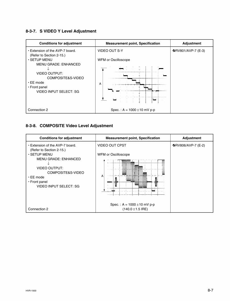
8-7HVR-1500
Measurement point, Specification
VIDEO OUT CPST
WFM or Oscilloscope
Spec. : A = 1000 ±10 mV p-p(140.0 ±1.5 IRE)
8-3-7. S VIDEO Y Level Adjustment
8-3-8. COMPOSITE Video Level Adjustment
Conditions for adjustment
. Extension of the AVP-7 board.(Refer to Section 2-15.)
. SETUP MENUMENU GRADE: ENHANCED
↓VIDEO OUTPUT:
COMPOSITE&S-VIDEO. EE mode. Front panel
VIDEO INPUT SELECT: SG
Connection 2
Adjustment
1RV806/AVP-7 (E-2)
A
Measurement point, Specification
VIDEO OUT S-Y
WFM or Oscilloscope
Spec. : A = 1000 ±10 mV p-p
Conditions for adjustment
. Extension of the AVP-7 board.(Refer to Section 2-15.)
. SETUP MENUMENU GRADE: ENHANCED
↓VIDEO OUTPUT:
COMPOSITE&S-VIDEO. EE mode. Front panel
VIDEO INPUT SELECT: SG
Connection 2
Adjustment
1RV801/AVP-7 (E-3)
A
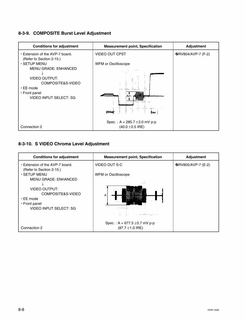
8-8 HVR-1500
Measurement point, Specification
VIDEO OUT S-C
WFM or Oscilloscope
Spec. : A = 677.5 ±0.7 mV p-p(87.7 ±1.0 IRE)
8-3-9. COMPOSITE Burst Level Adjustment
8-3-10. S VIDEO Chroma Level Adjustment
Conditions for adjustment
. Extension of the AVP-7 board.(Refer to Section 2-15.)
. SETUP MENUMENU GRADE: ENHANCED
↓VIDEO OUTPUT:
COMPOSITE&S-VIDEO. EE mode. Front panel
VIDEO INPUT SELECT: SG
Connection 2
Adjustment
1RV805/AVP-7 (E-2)
Measurement point, Specification
VIDEO OUT CPST
WFM or Oscilloscope
Spec. : A = 285.7 ±3.0 mV p-p(40.0 ±0.5 IRE)
Conditions for adjustment
. Extension of the AVP-7 board.(Refer to Section 2-15.)
. SETUP MENUMENU GRADE: ENHANCED
↓VIDEO OUTPUT:
COMPOSITE&S-VIDEO. EE mode. Front panel
VIDEO INPUT SELECT: SG
Connection 2
Adjustment
1RV804/AVP-7 (F-2)
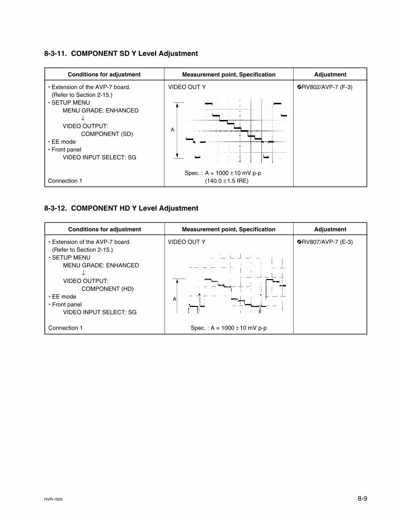
8-9HVR-1500
Measurement point, Specification
VIDEO OUT Y
Spec. : A = 1000 ±10 mV p-p
8-3-11. COMPONENT SD Y Level Adjustment
8-3-12. COMPONENT HD Y Level Adjustment
Conditions for adjustment
. Extension of the AVP-7 board.(Refer to Section 2-15.)
. SETUP MENUMENU GRADE: ENHANCED
↓VIDEO OUTPUT:
COMPONENT (HD). EE mode. Front panel
VIDEO INPUT SELECT: SG
Connection 1
Adjustment
1RV807/AVP-7 (E-3)
A
Measurement point, Specification
VIDEO OUT Y
Spec. : A = 1000 ±10 mV p-p(140.0 ±1.5 IRE)
Conditions for adjustment
. Extension of the AVP-7 board.(Refer to Section 2-15.)
. SETUP MENUMENU GRADE: ENHANCED
↓VIDEO OUTPUT:
COMPONENT (SD). EE mode. Front panel
VIDEO INPUT SELECT: SG
Connection 1
Adjustment
1RV802/AVP-7 (F-3)
A
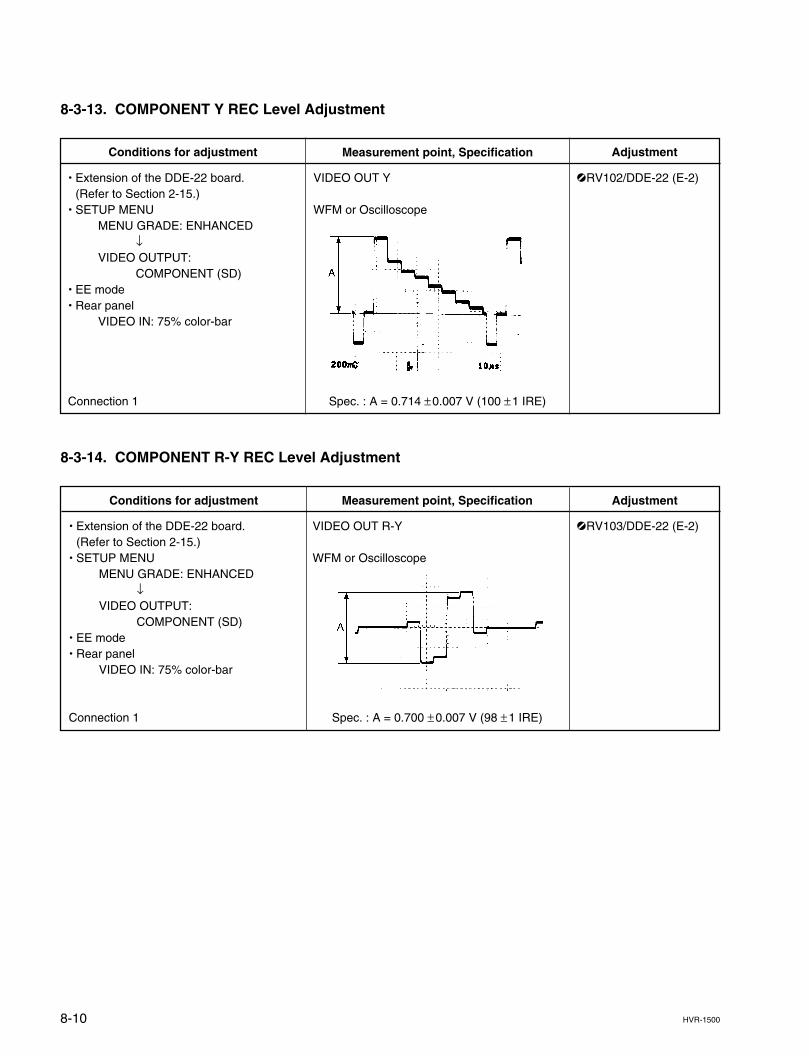
8-10 HVR-1500
Measurement point, Specification
VIDEO OUT R-Y
WFM or Oscilloscope
Spec. : A = 0.700 ±0.007 V (98 ±1 IRE)
8-3-13. COMPONENT Y REC Level Adjustment
8-3-14. COMPONENT R-Y REC Level Adjustment
Conditions for adjustment
. Extension of the DDE-22 board.(Refer to Section 2-15.)
. SETUP MENUMENU GRADE: ENHANCED
↓VIDEO OUTPUT:
COMPONENT (SD). EE mode. Rear panel
VIDEO IN: 75% color-bar
Connection 1
Adjustment
1RV103/DDE-22 (E-2)
Measurement point, Specification
VIDEO OUT Y
WFM or Oscilloscope
Spec. : A = 0.714 ±0.007 V (100 ±1 IRE)
Conditions for adjustment
. Extension of the DDE-22 board.(Refer to Section 2-15.)
. SETUP MENUMENU GRADE: ENHANCED
↓VIDEO OUTPUT:
COMPONENT (SD). EE mode. Rear panel
VIDEO IN: 75% color-bar
Connection 1
Adjustment
1RV102/DDE-22 (E-2)
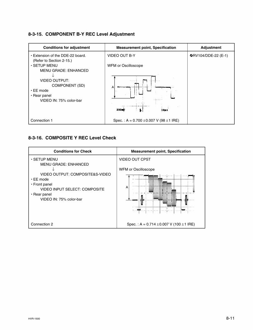
8-11HVR-1500
Measurement point, Specification
VIDEO OUT CPST
WFM or Oscilloscope
Spec. : A = 0.714 ±0.007 V (100 ±1 IRE)
8-3-15. COMPONENT B-Y REC Level Adjustment
8-3-16. COMPOSITE Y REC Level Check
Conditions for Check
. SETUP MENUMENU GRADE: ENHANCED
↓VIDEO OUTPUT: COMPOSITE&S-VIDEO
. EE mode
. Front panelVIDEO INPUT SELECT: COMPOSITE
. Rear panelVIDEO IN: 75% color-bar
Connection 2
A
Measurement point, Specification
VIDEO OUT B-Y
WFM or Oscilloscope
Spec. : A = 0.700 ±0.007 V (98 ±1 IRE)
Conditions for adjustment
. Extension of the DDE-22 board.(Refer to Section 2-15.)
. SETUP MENUMENU GRADE: ENHANCED
↓VIDEO OUTPUT:
COMPONENT (SD). EE mode. Rear panel
VIDEO IN: 75% color-bar
Connection 1
Adjustment
1RV104/DDE-22 (E-1)
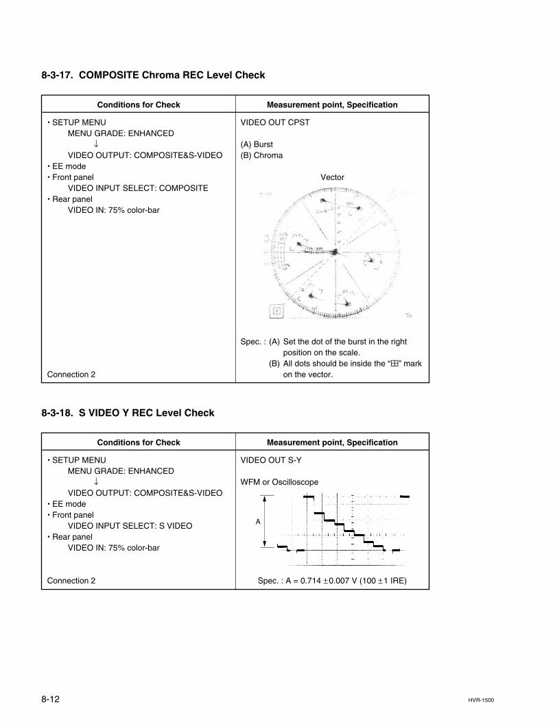
8-12 HVR-1500
Measurement point, Specification
VIDEO OUT CPST
(A) Burst(B) Chroma
Vector
Spec. : (A) Set the dot of the burst in the rightposition on the scale.
(B) All dots should be inside the “4” markon the vector.
8-3-17. COMPOSITE Chroma REC Level Check
Conditions for Check
. SETUP MENUMENU GRADE: ENHANCED
↓VIDEO OUTPUT: COMPOSITE&S-VIDEO
. EE mode
. Front panelVIDEO INPUT SELECT: COMPOSITE
. Rear panelVIDEO IN: 75% color-bar
Connection 2
Measurement point, Specification
VIDEO OUT S-Y
WFM or Oscilloscope
Spec. : A = 0.714 ±0.007 V (100 ±1 IRE)
8-3-18. S VIDEO Y REC Level Check
Conditions for Check
. SETUP MENUMENU GRADE: ENHANCED
↓VIDEO OUTPUT: COMPOSITE&S-VIDEO
. EE mode
. Front panelVIDEO INPUT SELECT: S VIDEO
. Rear panelVIDEO IN: 75% color-bar
Connection 2
A
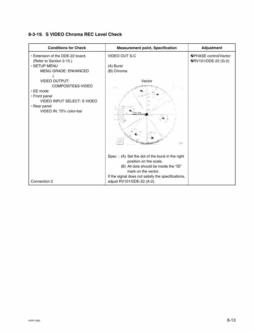
8-13HVR-1500
8-3-19. S VIDEO Chroma REC Level Check
Measurement point, Specification
VIDEO OUT S-C
(A) Burst(B) Chroma
Vector
Spec. : (A) Set the dot of the burst in the rightposition on the scale.
(B) All dots should be inside the “4”mark on the vector.
If the signal does not satisfy the specifications,adjust RV101/DDE-22 (A-2).
Conditions for Check
. Extension of the DDE-22 board.(Refer to Section 2-15.)
. SETUP MENUMENU GRADE: ENHANCED
↓VIDEO OUTPUT:
COMPOSITE&S-VIDEO. EE mode. Front panel
VIDEO INPUT SELECT: S VIDEO. Rear panel
VIDEO IN: 75% color-bar
Connection 2
Adjustment
1PHASE control/Vector1RV101/DDE-22 (G-2)
8-14 HVR-1500
8-3-20. Adjustment in the 50 Hz Mode
nBe sure to perform the adjustments in the 50 Hz mode after completing the adjustment in the 59.94 Hzmode.
1. Setting the Switches and SETUP MENUThis setting should be fixed in position unless otherwise specified.SETUP MENU
SYSTEM SEL: 50i (PAL)
2. ConnectionThe signal generator is switched to TSG-131A (for PAL).
3. Adjustment in the 50 Hz ModePerform the adjustments as follows.. HD HCK frequency adjustment (Refer to Section 8-3-3.). SYNC phase adjustment (Refer to Section 8-3-4.). CHARACTER DC adjustment (Refer to Section 8-3-5.). CF DET CENTER adjustment (Refer to Section 8-3-6.)
4. Setting the Switches and SETUP MENUThe setting is returned to the customer setting.
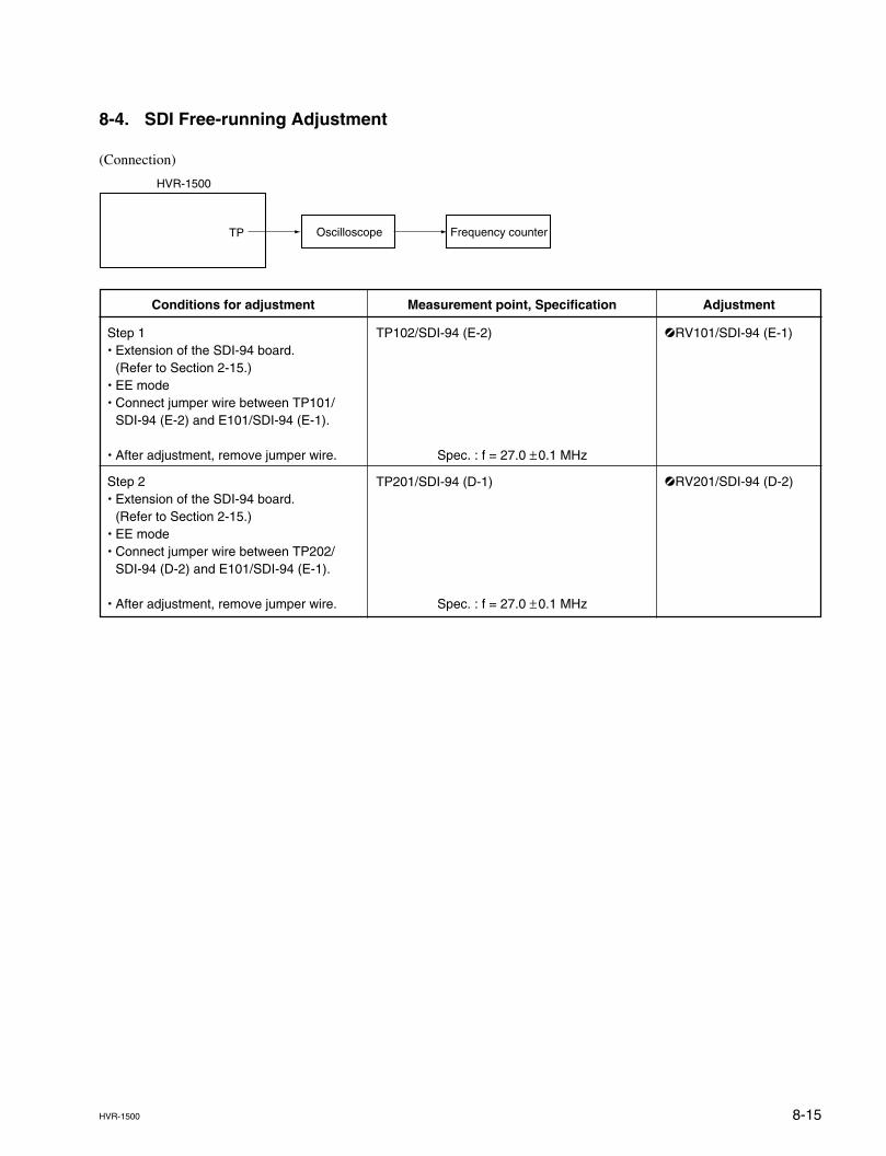
8-15HVR-1500
8-4. SDI Free-running Adjustment
(Connection)
TP
HVR-1500
Oscilloscope Frequency counter
Measurement point, Specification
TP102/SDI-94 (E-2)
Spec. : f = 27.0 ±0.1 MHz
TP201/SDI-94 (D-1)
Spec. : f = 27.0 ±0.1 MHz
Conditions for adjustment
Step 1. Extension of the SDI-94 board.
(Refer to Section 2-15.). EE mode. Connect jumper wire between TP101/
SDI-94 (E-2) and E101/SDI-94 (E-1).
. After adjustment, remove jumper wire.
Step 2. Extension of the SDI-94 board.
(Refer to Section 2-15.). EE mode. Connect jumper wire between TP202/
SDI-94 (D-2) and E101/SDI-94 (E-1).
. After adjustment, remove jumper wire.
Adjustment
1RV101/SDI-94 (E-1)
1RV201/SDI-94 (D-2)
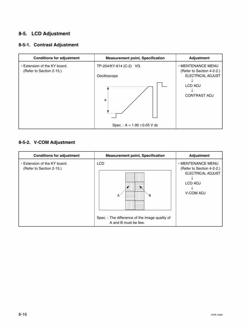
8-16 HVR-1500
Measurement point, Specification
TP-204/KY-614 (C-2) VG
Oscilloscope
Spec. : A = 1.90 ±0.05 V dc
Conditions for adjustment
. Extension of the KY board.(Refer to Section 2-15.)
8-5. LCD Adjustment
8-5-1. Contrast Adjustment
Adjustment
. MENTENANCE MENU(Refer to Section 4-2-2.)
ELECTRICAL ADJUST↓
LCD ADJ↓
CONTRAST ADJ
8-5-2. V-COM Adjustment
Measurement point, Specification
LCD
Spec. : The difference of the image quality ofA and B must be few.
Conditions for adjustment
. Extension of the KY board.(Refer to Section 2-15.)
Adjustment
. MENTENANCE MENU(Refer to Section 4-2-2.)
ELECTRICAL ADJUST↓
LCD ADJ↓
V-COM ADJ
A
A B
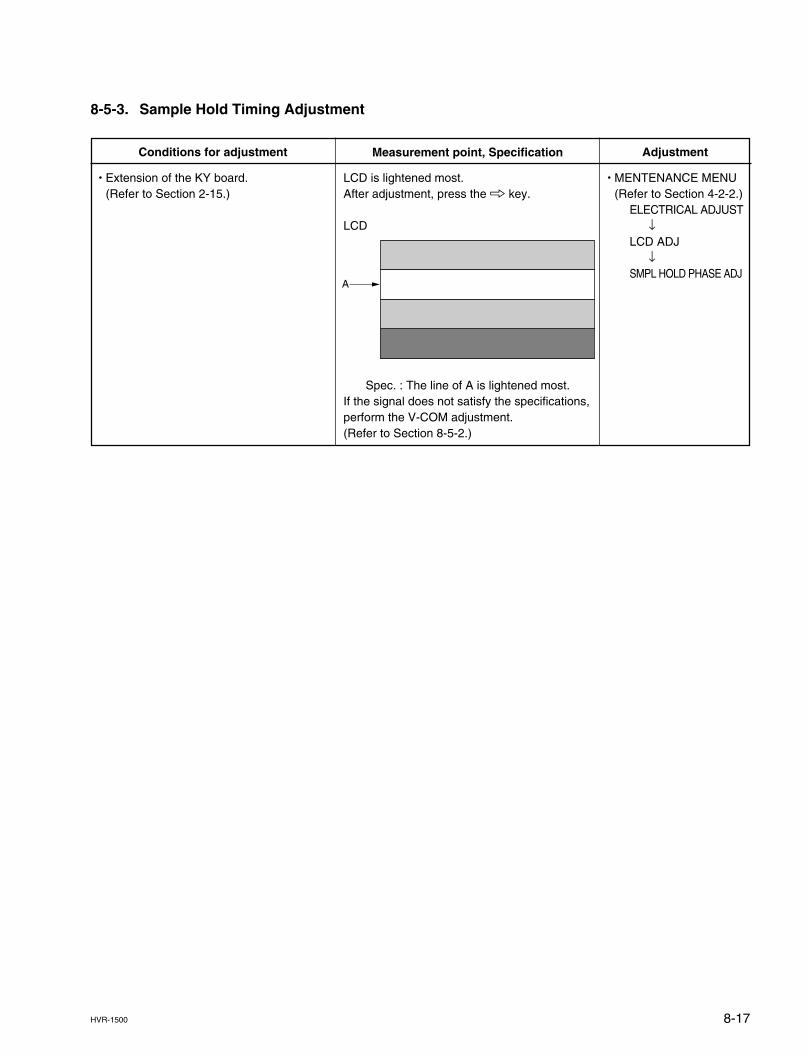
8-17HVR-1500
8-5-3. Sample Hold Timing Adjustment
Measurement point, Specification
LCD is lightened most.After adjustment, press the 8 key.
LCD
Spec. : The line of A is lightened most.If the signal does not satisfy the specifications,perform the V-COM adjustment.(Refer to Section 8-5-2.)
Conditions for adjustment
. Extension of the KY board.(Refer to Section 2-15.)
Adjustment
. MENTENANCE MENU(Refer to Section 4-2-2.)
ELECTRICAL ADJUST↓
LCD ADJ↓
SMPL HOLD PHASE ADJA
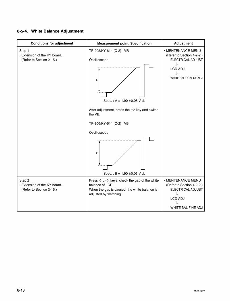
8-18 HVR-1500
8-5-4. White Balance Adjustment
Measurement point, Specification
TP-205/KY-614 (C-2) VR
Oscilloscope
Spec. : A = 1.90 ±0.05 V dc
After adjustment, press the 8 key and switchthe VB.
TP-206/KY-614 (C-2) VB
Oscilloscope
Spec. : B = 1.90 ±0.05 V dc
Press 7, 8 keys, check the gap of the whitebalance of LCD.When the gap is caused, the white balance isadjusted by watching.
Conditions for adjustment
Step 1. Extension of the KY board.
(Refer to Section 2-15.)
Step 2. Extension of the KY board.
(Refer to Section 2-15.)
Adjustment
. MENTENANCE MENU(Refer to Section 4-2-2.)
ELECTRICAL ADJUST↓
LCD ADJ↓
WHITE BAL COARSE ADJ
. MENTENANCE MENU(Refer to Section 4-2-2.)
ELECTRICAL ADJUST↓
LCD ADJ↓
WHITE BAL FINE ADJ
A
B
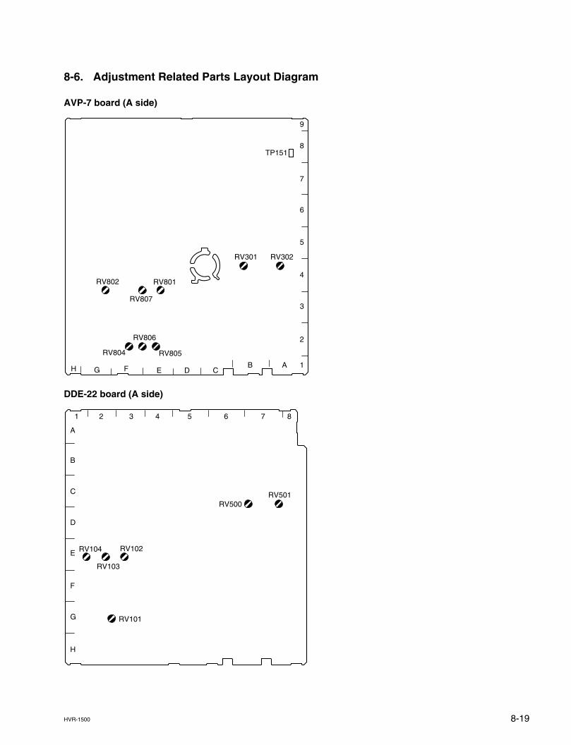
8-19HVR-1500
8-6. Adjustment Related Parts Layout Diagram
AVP-7 board (A side)
DDE-22 board (A side)
9
8
7
6
5
4
3
2
1ABCDEFH G
RV302RV301
TP151
RV801
RV807
RV802
RV804 RV805
RV806
1
A
B
C
D
E
F
G
H
2 3 4 5 6 7 8
RV501RV500
RV104
RV103
RV102
RV101
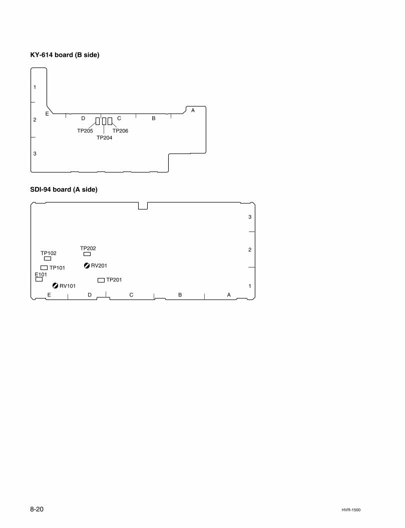
8-20 HVR-1500
KY-614 board (B side)
SDI-94 board (A side)
1
2
3
A
BCDE
TP205 TP206TP204
E D C B A
1
2
3
RV201
TP202
TP201
TP102
TP101E101
RV101
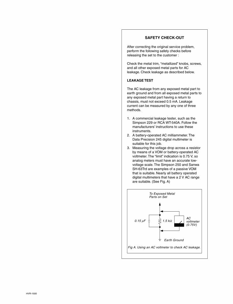
HVR-1500
SAFETY CHECK-OUT
After correcting the original service problem,perform the following safety checks beforereleasing the set to the customer :
Check the metal trim, “metallized” knobs, screws,and all other exposed metal parts for ACleakage. Check leakage as described below.
LEAKAGE TEST
The AC leakage from any exposed metal part toearth ground and from all exposed metal parts toany exposed metal part having a return tochassis, must not exceed 0.5 mA. Leakagecurrent can be measured by any one of threemethods.
1. A commercial leakage tester, such as theSimpson 229 or RCA WT-540A. Follow themanufacturers’ instructions to use theseinstruments.
2. A battery-operated AC milliammeter. TheData Precision 245 digital multimeter issuitable for this job.
3. Measuring the voltage drop across a resistorby means of a VOM or battery-operated ACvoltmeter. The “limit” indication is 0.75 V, soanalog meters must have an accurate low-voltage scale. The Simpson 250 and SanwaSH-63Trd are examples of a passive VOMthat is suitable. Nearly all battery operateddigital multimeters that have a 2 V AC rangeare suitable. (See Fig. A)
To Exposed MetalParts on Set
Fig A. Using an AC voltmeter to check AC leakage.
ACvoltmeter(0.75V)
Earth Ground
0.15 µF 1.5 kZ

Printed in Japan
Sony Corporation 2007. 4 08
©2007
HVR-1500 (SY) E
9-968-316-01