Embed Size (px)
DESCRIPTION
Digital Logic issues in Embedded Systems. Things upcoming. HW3 due on Tuesday Feb 18 th Can’t do 1h. Proposals due Thursday Feb 20 th by 1:30pm Mail to Matt and Mark Project proposal meetings next Friday Will create Doodle. Exam on Tuesday the 25 th in class. - PowerPoint PPT Presentation
Citation preview
Digital Logic issuesin Embedded Systems
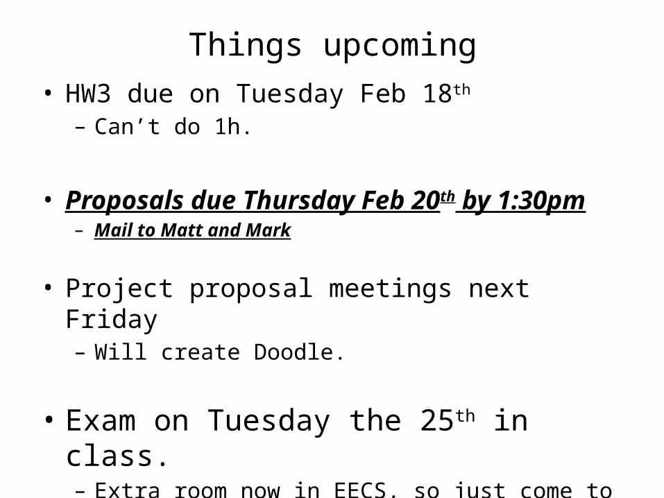
Things upcoming• HW3 due on Tuesday Feb 18th
– Can’t do 1h.
• Proposals due Thursday Feb 20th by 1:30pm– Mail to Matt and Mark
• Project proposal meetings next Friday– Will create Doodle.
• Exam on Tuesday the 25th in class.– Extra room now in EECS, so just come to the classroom.
Today
• Finish advanced digital logic for embedded systems.– Work example designs on board
• Discuss timers (time allowing)

EECS 270++
Our digital logic class, EECS 270, does a great job dealing with logic basics. But it only has so much time and has a wide variety of follow-on classes (373, 470, 478) to support.
Today we’ll spend time reviewing some 270 material, introducing some new material, and providing design guidelines. We’ll then wrap it working on a rather difficult digital design problem involving interfacing.
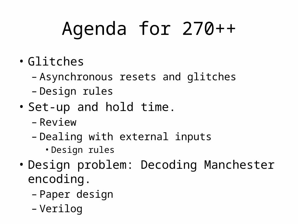
Agenda for 270++
• Glitches– Asynchronous resets and glitches– Design rules
• Set-up and hold time.– Review– Dealing with external inputs
• Design rules
• Design problem: Decoding Manchester encoding.– Paper design– Verilog

Glitches
• Combinational logic can glitch– What is a glitch?– How do we normally deal with it?– Where can it hurt us?

Full adder (from Wikipedia)
Timing
• Assuming the XOR gates have a delay of 0.2ns while AND and OR gates have a delay of 0.1ns– What is the worst
case propagation delay for this circuit?
x
y
z

x
y
zFull adder (from Wikipedia)
Consider the adjacent circuit diagram. Assuming the XOR gates have a delay of 0.2ns while AND and OR gates have a delay of 0.1ns, fill inthe following chart.
Only selected causalityarrows shown…
Glitches

Glitching: a summary
• When input(s) change, the output can be wrong for a time. However, that time is bound.
– And more so, the output can change during this “computation time” even if the output ends up where it started!

Effect of Glitches
• Think back to EECS 370.– Why don’t glitches cause errors?
– The trick is that the inputs all change at the same time• In this case, the ID/EX registers all change
some time shortly after the rising edge of the clock.
– And we’ve chosen the clock period such that the next edge doesn’t happen until the combinational logic has stopped glitching.• In fact, we use the worst-case combinational
logic delay in the whole system when determining the clock period!

So, how can glitches hurt us?
• There are a handful of places:– Asynchronous resets
• If you’ve got a flip-flop that has an asynchronous reset (or “preset”) you need to be sure the input can’t glitch.– That pretty much means you need a flip-flop
driving the input (which means you probably should have used a sync. reset!)
– Clocks• If you are using combinational logic to drive a
clock, you are likely going to get extra clock edges.
Traditionally, CLR is usedto indicate async reset. “R”or “reset” for sync. reset.
If clk is high and cond glitches, you get extra edges!
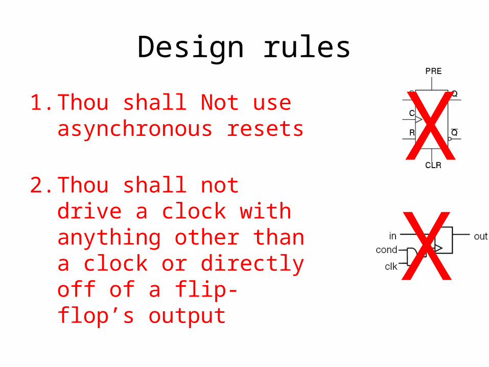
Design rules
1. Thou shall Not use asynchronous resets
2. Thou shall not drive a clock with anything other than a clock or directly off of a flip-flop’s output
XX

Really?
• I mean people use asynchronous resets and clock gating!– Yep. And people use goto in C programs.
• Sometimes they are the right thing.– But you have to think really hard about them to insure that they won’t cause you
problems.
– Our “simple” bus usedcombinational logic forthe clock• Works because REQ goes
low only after everythingelse has stopped switching– So no glitch.
• Not fun to reason about…
• Avoid unless you must– Then think really carefully.

Agenda
• Glitches– Asynchronous resets and glitches– Design rules
• Set-up and hold time.– Review– Dealing with external inputs
• Design rules
• Fun with buses: Tristate and pull-up• Design problem: Decoding Manchester encoding.
– Paper design– Verilog
• Bonus issue– Bit stuffing
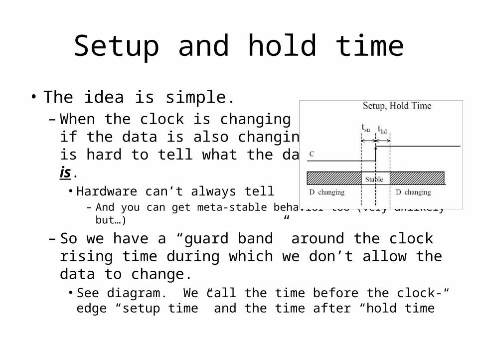
Setup and hold time
• The idea is simple.– When the clock is changing
if the data is also changing itis hard to tell what the datais. • Hardware can’t always tell
– And you can get meta-stable behavior too (very unlikely but…)
– So we have a “guard band” around the clock rising time during which we don’t allow the data to change.• See diagram. We call the time before the clock-edge “setup
time” and the time after “hold time”
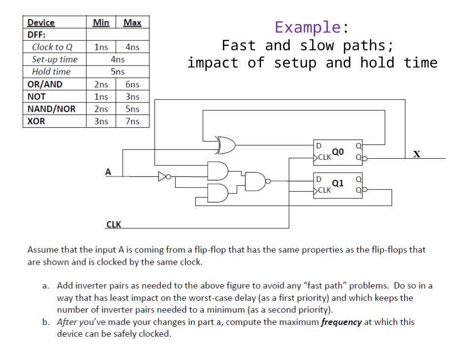
Example:Fast and slow paths;
impact of setup and hold time
So what happens if we violate set-up or hold time?
• Often just get one of the two values.– And that often is just fine.
• Consider getting a button press from the user.• If the button gets pressed at the same time as the clock
edge, we might see the button now or next clock.– Either is generally fine when it comes to human input.
– But bad things could happen.• The flip-flop’s output might not settle out to a “0” or a “1”
– That could cause latter devices to mess up.
• More likely, if that input is going to two places, one might see a “0” the other a “1”.
Example
• A common thing to do is reset a state machine using a button.– User can “reset” the system.
• Because the button transition could violate set-up or hold time, some state bits of the state machine might come out of reset at different times.– And you quickly end up at a wrong or illegal state.
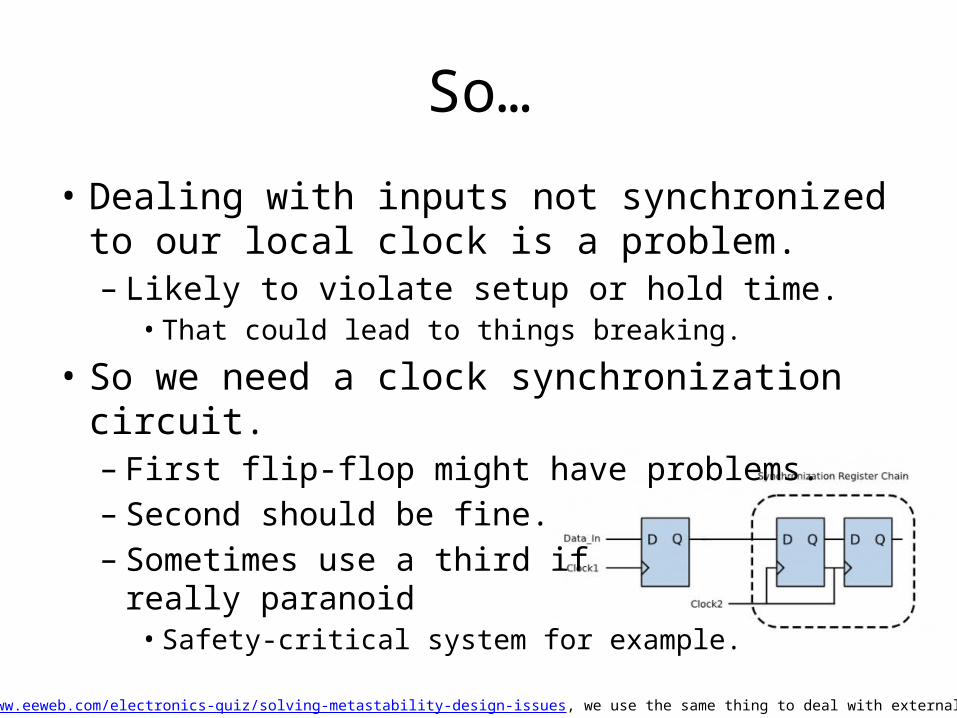
So…
• Dealing with inputs not synchronized to our local clock is a problem.– Likely to violate setup or hold time.• That could lead to things breaking.
• So we need a clock synchronization circuit.– First flip-flop might have problems.– Second should be fine.– Sometimes use a third if
really paranoid• Safety-critical system for example.
Figure from http://www.eeweb.com/electronics-quiz/solving-metastability-design-issues, we use the same thing to deal with external inputs too!
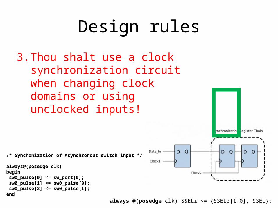
Design rules
3. Thou shalt use a clock synchronization circuit when changing clock domains or using unclocked inputs!
/* Synchonization of Asynchronous switch input */
always@(posedge clk)begin sw0_pulse[0] <= sw_port[0]; sw0_pulse[1] <= sw0_pulse[0]; sw0_pulse[2] <= sw0_pulse[1];end
always @(posedge clk) SSELr <= {SSELr[1:0], SSEL};

Two design problems
• Design device which divides an input clock by 16 and has a 75% duty cycle– Output used as a clock.
• Manchester encoding– Basics• Scheme• Self timing etc.
– Design problem

Time for Timers
Timers are used for…
• Measuring time
• Causing an event at a regular interval

Measuring time
• When would you use a timer to measure time?
• How could you make that measurement accurate?– Issue with throwing interrupt on event and
checking timer?
“Capture register”
Causing an event at a regular interval
• What type of event?
• How would you make that regular interval as regular as possible?– Issues with polling?
“Reference register”
Virtualizing timers

Control and complexity
• You need a way to tell the timer what to do.– Set reference, read capture, reset timer, etc.– Some timers are extremely complex.
• So have lots of memory-mappedregisters– Control, prescaler, etc.
• Some can do really cool things– PWM, etc.

always@(posedge pclk)if(~nreset) begin overflowReset <= 1'b0; controlReg <= 32'h00000000; overflowReg <= 32'h00000000; endelse begin if(bus_write_en) begin : WRITE case(bus_addr[3:2]) 2'b00: // Timer Overflow Register begin overflowReg <= bus_write_data; overflowReset <= 1'b1; end 2'b01: // Timer Value, Read Only begin overflowReset <= 1'b0; end 2'b10: // Timer Control begin controlReg <= bus_write_data; overflowReset <= 1'b0; end 2'b11: // Spare begin overflowReset <= 1'b0; end endcaseend
else if(bus_read_en) begin : READ case(bus_addr[3:2])
2'b00: // Timer Overflow register begin
bus_read_data <= overflowReg; end 2'b01: // Timer Value, Read Only begin bus_read_data <= counterReg;
end 2'b10: // Timer Control begin bus_read_data <= controlReg;
end 2'b11: // Spare begin end endcase endelse overflowReset <= 1'b0;end