Embed Size (px)
Citation preview
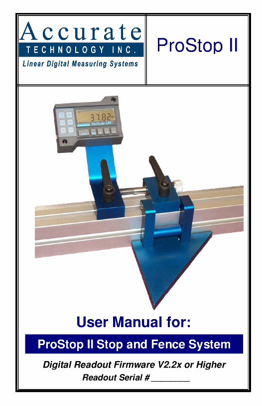
Digital Readout Firmware V2.2x or Higher Readout Serial # ________

ProStop Page 2 of 24
WARRANTY
Accurate Technology, Inc., warrants the ProStop System against defective parts and workmanship for 1 year commencing from the date of original purchase. Upon notification of a defect, Accurate Technology, Inc., shall have the option to repair or replace any defective part. Such services shall be the customer's sole and exclusive remedy. Expenses incidental to repair, maintenance, or replacement under warranty, including those for labor and material, shall be borne by Accurate Technology, Inc. (Including freight or transportation charges during the first 30 days).
Except as expressly provided in this warranty, Accurate Technology, Inc., does not make any warranties with respect to the product, either expressed or implied, including implied warranties of merchantability or fitness for a particular purpose, except as expressly provided in this agreement.
Accurate Technology, Inc., shall not be liable for any special, incidental, or consequential damages or for loss, damage or expense directly or indirectly arising from the customer's use of or inability to use the equipment either separately or in combination with other equipment, or for personal injury or loss or destruction of other property, or from any other cause.
To request repair work (either warranty qualified parts or not), contact Accurate Technology, Inc. directly by phone, fax, or e-mail. A Returned Merchandise Authorization (RMA) number is required before returning a product for repair.
Accurate Technology, Inc. +1 828.654.7920 800.233.0580 828.654.8824 (F)
www.proscale.com [email protected]
��������� ����� ��� � � � � � �� �� � � � � � � ��� �� ��� �� � � � � � � � � � � � � � !� � � �"� � #��� !!�� � � �� �� � � � � � � $ #�
SSAAFFEETTYY WWAARRNNIINNGG
Before installing ProStop on any machinery:
Turn off machine and disconnect power.

Accurate Technology Page 3 of 24
Table of Contents
SECTION 1 GENERAL INFORMATION ......................................................... 4 Introduction ............................................................................................. 4 What This Manual Includes ...................................................................... 4 ProStop II Specifications .......................................................................... 4
SECTION 2 PROSTOP ............................................................................ 5 Assembly of ProStop ............................................................................... 5 Assembly of 45/90 Stop ........................................................................... 6
SECTION 3 PROSTOP OPERATION ........................................................... 7 Mounting................................................................................................. 7 Calibration .............................................................................................. 7 Operation................................................................................................ 7 Maintenance ........................................................................................... 8 Changing the Batteries............................................................................. 8
SECTION 4 DRO OPERATION .................................................................. 9 The DRO LCD......................................................................................... 9 Programming .......................................................................................... 9 Programming Parameters .......................................................................10 Primary Key Functions ............................................................................15
MODE ...............................................................................................15 Auxiliary Keypad Functions .....................................................................16
ABS -INC ................................................................................16 SEND ................................................................................................18
Display Functions ...................................................................................19 Lock Mode .........................................................................................19 Offset Addition....................................................................................19 Limit Mode .........................................................................................19 Scaling ..............................................................................................19 Jumpers.............................................................................................20
Programming Summary ..........................................................................21 Key Press Function Summary .................................................................22
SECTION 5 MISCELLANEOUS..................................................................23 Frequently Asked Questions....................................................................23

ProStop Page 4 of 24
SECTION 1 GENERAL INFORMATION Introduction
ProStop II is a general purpose Digital Stop & Fence System. It is ideal for use on Miter saws, Chop Saws, Radial Arm Saws or any other application where a moveable stop along a fixed back fence is desired. It has been designed using high quality extruded and machined parts to provide the best accuracy and repeatability.
The core technology of the ProPanel is a ProScale™ Measuring System. ProScale measuring systems are affordable precision electronic devices for making linear measurements with speed and accuracy. ProScale consists of a SCALE, an Encoder (also called a readhead) and a Digital Readout (DRO). ProStop uses Inductive measurement technology, the same technology used in newer high quality digital calipers.
What This Manual Includes This manual includes information for:
ProStop II Digital Stop and Fence System supplied with an LCD Readout and Firmware V2.2x or higher, manufactured after 7-20-2007.
(The F/W version is displayed on power-up or when power is cycled.)
ProStop II Specifications Measuring Range: 52 inches, 96 inches 120 inches, 234 inches Accuracy: + .010 inch Resolution Reduced: .1mm/.01cm/.01in; Normal: .01mm/.001cm/.001in; Increased: .01mm/.001cm/.0004in Repeatability: .01mm or .001cm or .001in DRO Display Range: + 9999.99 mm; + 999.999 cm; + 999.999 in; + 399 63/64 in Operating Temp: 0 to 50°C; 32 to 120°F Max. Slew Rate: 40 inches/second (1000 mm/sec.) Encoder: Six-conductor cable terminated by RJ12 modular Dimensions: Available at www.proscale.com. Warranty: One year from date of purchase. Battery Life: 8-12 months

Accurate Technology Page 5 of 24
SECTION 2 PROSTOP ProStop II is a complete digital (flip) stop and fence system for chop saws, radial arm saws, and miter saws.
ProStop II is easy to install. By following the basics of good installation error-free operation can be expected. ProStop II can be installed on many different types and brands of equipment, so all installations will be different. Therefore, it's the responsibility of the installer to choose the bolts, screws, or other mounting hardware that guarantee proper installation for optimum operation.
Assembly of ProStop Each ProStop II shipped from Accurate Technology will have two packages. The first contains the linear scale and fence extrusion. The second package contains the readhead, digital stop, and mounting hardware. These parts should be assembled prior to mounting the ProStop II.
1. Encoder installation: Carefully slide the encoder on the scale. The wire should exit down. 2. Stop Installation: Loosen the lock handle and slide the stop on to the fence extrusion, while guiding the lock nut into the upper slot on the fence extrusion. 3. Slide the encoder under the Guide Clip so that the post on the readhead is engaged in the slot of the Guide Clip. 4. Plug the encoder into the DRO. 5. Move the stop assembly left to right and note if the DRO readings increase or decrease. Depending upon the installation, it may be necessary to program the DRO to reverse the reading direction. (Section 4: PROGRAMMING) The Encoder cable will exit toward the bottom �

ProStop Page 6 of 24
Assembly of 45/90 Stop This assembly may have been performed at the factory and will not need to be repeated. 1. Attach the DRO bracket to the fine
adjustment block (as shown).
2. Remove the lower round spacer
from the flip stop assembly.
3. Slide the 45/90 stop plate onto the flip stop assembly and tighten mounting bolts The 45/90 plate may be mounted with the 45° or the 90° face toward the saw.
Calibrate the stop system. See Section 3

Accurate Technology Page 7 of 24
SECTION 3 PROSTOP OPERATION
Mounting 1. Position the fence system so it is as close to 90 degrees with respect to the
blade as possible. 2. The included installation nuts fit the T-slot in the bottom of the fence
extrusion. These nuts can be used with the included bolts to mount the ProStop from the bottom.
Calibration Once installed, ProStop can be calibrated easily and quickly. Following is an example of calibrating ProStop for a cutoff saw application. Other installations follow the same general procedure.
1. Check to be sure installation of all parts is complete, all fasteners are secure and the Encoder is plugged into the DRO.
2. Cut a part using your normal operation. 3. Measure the length of the part with the most precise measuring tool
available (i.e. digital calipers). 4. Press the zero key on the DRO. 5. Press and hold the PLUS key to scroll until the measurement is displayed.
(The longer the PLUS key is held down, the faster the display will scroll.) 6. When the proper reading is reached, lock the DRO if desired. This prevents
accidentally re-zeroing of the DRO. See (Section 4: DRO FUNCTIONS)
7. Re-calibrate, if necessary, after changing saw blade (or applicable tooling).
Operation 1. Flip the stop down. 2. Unlock the stop by turning the lock handle(s) 180 degrees
counterclockwise. 3. Slide the stop into the desired position. If using the fine adjustment option:
a. Slide the stop to the approximate position. b. Turn the lock handle on the fine adjustment block until it is locked. c. Turn the fine adjust knob to fine position the stop. (Each full turn is
0.050 inches.) 4. Turn the lock handle on the stop block until it is locked. 5. Make necessary cuts. 6. When not in use, the stop may be flipped up. (The lock handle should be
facing to the rear of the stop.)
ProStop Page 8 of 24
Maintenance The fence extrusion should be cleaned of all debris often. Do not use any liquid lubricants on the scale assembly, as this may: a. Impede the encoder’s ability to operate properly. b. Attract other contaminants to the scale. 2. The DRO should be cleaned periodically with compressed air to remove any dust on the lens and keys. All fasteners should occasionally be checked for tightness.
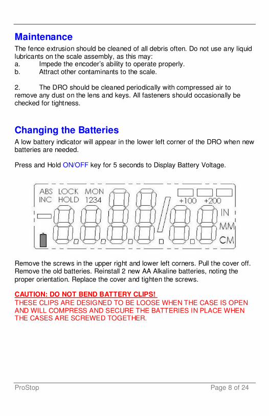
Changing the Batteries A low battery indicator will appear in the lower left corner of the DRO when new batteries are needed.
Press and Hold ON/OFF key for 5 seconds to Display Battery Voltage.
Remove the screws in the upper right and lower left corners. Pull the cover off. Remove the old batteries. Reinstall 2 new AA Alkaline batteries, noting the proper orientation. Replace the cover and tighten the screws.
CAUTION: DO NOT BEND BATTERY CLIPS! THESE CLIPS ARE DESIGNED TO BE LOOSE WHEN THE CASE IS OPEN AND WILL COMPRESS AND SECURE THE BATTERIES IN PLACE WHEN THE CASES ARE SCREWED TOGETHER.

Accurate Technology Page 9 of 24
SECTION 4 DRO OPERATION This section covers the programming and operation of the ProStop DRO Firmware* V2.2 or higher. If your DRO Firmware is prior to 2.2, or your DRO is different than the DRO described here, you must use the appropriate user manual for that system. * (The F/W version is displayed on power-up or when power is cycled.)
The DRO LCD
The above figure illustrates all the segments available on the DRO.
Pressing and holding the ON/OFF and MODE key for 10 seconds with power off will perform a full segment LCD test AND set all programming parameters to factory defaults. NOTE: ALL PROSTOP SPECIFIC SETTINGS WILL BE LOST !!
Programming Several functions of the Display are user programmable. The following describes what features are available and how to change the system’s factory defaults to customize the Display for your application.
The keys pictured below have multiple functions. Timing, or how long a key is depressed, and the combination of the keys pressed is important. This manual uses the term “momentarily” to describe a key press of typically less than 1 second. Whereas “press and hold” is used to imply a key press of typically longer than 1.5 seconds. As an example: When using a computer keyboard to type a capital letter you “press and hold” the SHIFT key and “momentarily” depress the appropriate LETTER key. The “function” associated with key(s) pressed is executed on the key RELEASE, not the key DEPRESS. This is important since some keys execute different functions based on how long they are depressed.

ProStop Page 10 of 24
To enter PROGRAMMING MODE, press and hold the MODE key and then momentarily press the 0 (zero) key. The MODE key must be held for 1 second before the depression of the 0 (zero) key.
Once you are in the Programming Mode, momentarily pressing the MODE key will advance through the Programming Parameter list.
To step backwards in the Programming Parameter list press and hold the ON/OFF key and momentarily press the MODE key.
Momentarily pressing the + (plus) key while displaying a Programming Parameter will increase the parameter setting.
Momentarily pressing the -(minus) key while displaying a Programming Parameter will decrease the parameter setting.
Momentarily pressing the 0 (zero) key while displaying a Programming Parameter will rest the parameter to its factory default setting.
To exit PROGRAMMING MODE, press and hold the MODE key and then momentarily press the 0 (zero) key. NOTE: The Display will automatically exit PROGRAMMING MODE after 60 seconds of no key activity.
Programming Parameters Programming Parameters are listed below. Values in [ ] are the available range of values that can be programmed for that entry. Factory defaults are shown in Red.
Programming Parameters specific to ProStop are shown highlighted.
Programming Parameters that do not apply to ProStop are shown in Gray
Some Programming parameters, Offset Addition and Limit mode, indicate a ‘factory default set in inches’. The equivalent offset/limit value in mm or cm is applied if you switch the measurement MODE of the Display to mm or cm. (ie. If 5.00(in) is set, when the DRO is switched to mm the programmed offset/limit is now 127mm.)
Accurate Technology Page 11 of 24
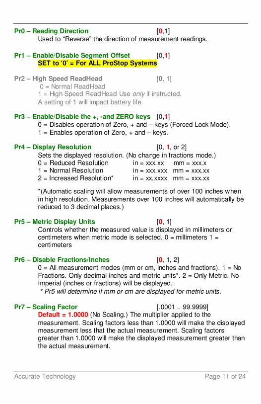
Pr0 – Reading Direction [0,1] Used to “Reverse” the direction of measurement readings.
Pr1 – Enable/Disable Segment Offset [0,1]
SET to ‘0’ = For ALL ProStop Systems
Pr2 – High Speed ReadHead [0, 1] 0 = Normal ReadHead 1 = High Speed ReadHead Use only if instructed. A setting of 1 will impact battery life.
Pr3 – Enable/Disable the +, -and ZERO keys [0,1] 0 = Disables operation of Zero, + and – keys (Forced Lock Mode). 1 = Enables operation of Zero, + and – keys.
Pr4 – Display Resolution [0, 1, or 2] Sets the displayed resolution. (No change in fractions mode.) 0 = Reduced Resolution in = xxx.xx mm = xxx.x 1 = Normal Resolution in = xxx.xxx mm = xxx.xx 2 = Increased Resolution* in = xx.xxxx mm = xxx.xx
*(Automatic scaling will allow measurements of over 100 inches when in high resolution. Measurements over 100 inches will automatically be reduced to 3 decimal places.)
Pr5 – Metric Display Units [0, 1] Controls whether the measured value is displayed in millimeters or centimeters when metric mode is selected. 0 = millimeters 1 = centimeters
Pr6 – Disable Fractions/Inches [0, 1, 2] 0 = All measurement modes (mm or cm, inches and fractions). 1 = No Fractions. Only decimal inches and metric units*. 2 = Only Metric. No Imperial (inches or fractions) will be displayed. * Pr5 will determine if mm or cm are displayed for metric units.
Pr7 – Scaling Factor [.0001 .. 99.9999] Default = 1.0000 (No Scaling.) The multiplier applied to the measurement. Scaling factors less than 1.0000 will make the displayed measurement less that the actual measurement. Scaling factors greater than 1.0000 will make the displayed measurement greater than the actual measurement.
ProStop Page 12 of 24
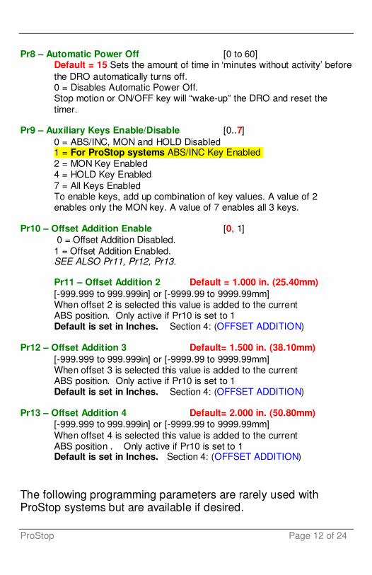
Pr8 – Automatic Power Off [0 to 60]
Default = 15 Sets the amount of time in ‘minutes without activity’ before the DRO automatically turns off. 0 = Disables Automatic Power Off. Stop motion or ON/OFF key will “wake-up” the DRO and reset the timer.
Pr9 – Auxiliary Keys Enable/Disable [0..7] 0 = ABS/INC, MON and HOLD Disabled 1 = For ProStop systems ABS/INC Key Enabled 2 = MON Key Enabled 4 = HOLD Key Enabled 7 = All Keys Enabled To enable keys, add up combination of key values. A value of 2 enables only the MON key. A value of 7 enables all 3 keys.
Pr10 – Offset Addition Enable [0, 1] 0 = Offset Addition Disabled. 1 = Offset Addition Enabled. SEE ALSO Pr11, Pr12, Pr13.
Pr11 – Offset Addition 2 Default = 1.000 in. (25.40mm) [-999.999 to 999.999in] or [-9999.99 to 9999.99mm] When offset 2 is selected this value is added to the current ABS position. Only active if Pr10 is set to 1 Default is set in Inches. Section 4: (OFFSET ADDITION)
Pr12 – Offset Addition 3 Default= 1.500 in. (38.10mm) [-999.999 to 999.999in] or [-9999.99 to 9999.99mm] When offset 3 is selected this value is added to the current ABS position. Only active if Pr10 is set to 1 Default is set in Inches. Section 4: (OFFSET ADDITION)
Pr13 – Offset Addition 4 Default= 2.000 in. (50.80mm) [-999.999 to 999.999in] or [-9999.99 to 9999.99mm] When offset 4 is selected this value is added to the current ABS position . Only active if Pr10 is set to 1 Default is set in Inches. Section 4: (OFFSET ADDITION)
The following programming parameters are rarely used with ProStop systems but are available if desired.

Accurate Technology Page 13 of 24
Pr14 – Output Signal Mode [0, 1] Configures the hardware output signal for activation on MONitor drift conditions or Upper/Lower limit alarm conditions. 0 = Monitor drift 1 = Limit Alarm
SEE ALSO Pr15, Pr16, Pr17
Pr15 – Output Polarity [0, 1] Used to configure the signal output. 0 = N/O, the output is Normally Open (not conducting to ground). 1 = N/C, the output is Normally Closed (conducting to ground).
Pr16 – Lower Limit Default = 0.000 in. (0.00mm) [-999.999 to 999.999in] or [-9999.99 to 9999.99mm] Sets the lower limit value.
Pr17 – Upper Limit Default = 5.000 in. (127.00mm) [-999.999 to 999.999in] or [-9999.99 to 9999.99mm] Sets the upper limit value.
Pr18 – Drift Tolerance Default =.010 in. (.254mm) [.001 to 999.999in] or [.01 to 9999.99mm ] Range of motion allowed (+ or -) while in MONitor mode.
Pr19 – Automatic Monitor ON Time [0, 1 or 2] Configures Display to automatically activate MONitor mode after 30 or 60 seconds of Encoder inactivity. 0 = disabled 1 = 30 seconds 2 = 60 seconds
Pr20 – Automatic Monitor OFF Enable [0, 1] Configures Display to automatically exit MONitor mode after a programmed distance (Pr21) has been exceeded from the drift tolerance position (Pr18). 0 = disabled 1 = enabled
Pr21 – Automatic Monitor OFF Distance Default = 0.500 in. (12.70mm)
[0.001 to 999.999in] or [0.01 to 9999.99mm]. The distance that must be exceeded from the drift tolerance position (Pr18) to deactivate monitor mode.) Active only when Pr20=1.

ProStop Page 14 of 24
Pr22 – Backlight ON time [0, 1, 2, 3 or 4] No longer available.
Pr 23 Future Use [1] DO NOT CHANGE
Pr 24 Display RF Address [0 to 63] This parameter is used to set the address of the Display. 0= (RF off)
Pr 25 RF System ID [0 to 31] This parameter is used to set the ID of the RF system.
Pr 26 Noise Suppression [0..7] This setting helps filter error causing interference caused by stray electrical noise when the Display is mounted on or around a machine. 0 = Minimum filtering 7 = Maximum filtering
Pr 27 Accuracy Compensation Enable [0, 1] This parameter does not work with ProStop systems.
Pr 28 Compensation Multiple [5] This parameter does not work with ProStop systems.

Accurate Technology Page 15 of 24
Primary Key Functions
ON/OFF Momentarily pressing the ON/OFF key will cause the Display to turn on or off. The Firmware Version is momentarily displayed on power-up. While on, if no key presses or positional changes occur within 15 minutes*, the Display will automatically turn itself off to conserve battery life. While off, if a positio n change is detected (larger than .05mm or .002in), the Display will automatically turn itself on with no loss of measurement information. *(Programming Parameter Pr8)
Holding the ON/OFF key for 5 seconds while the Display is turned on will display internal battery voltage.
Pressing and holding the ON/OFF and MODE key for 10 seconds with power off will perform a full segment LCD test AND set all programming parameters to factory defaults.
ANY PROSTOP SPECIFIC SETTINGS WILL BE LOST !!
MODE The ProStop can display measurement information in Inch or Metric. To change the display mode, momentarily press the MODE key. With each key press, the Display will cycle through decimal inches, fractional inches* (1/16), (1/32), (1/64) and metric (mm or cm based on setting of Programming Parameter Pr5). * If enabled by Programming Parameter Pr6.
When the DRO is in 1/16 or 1/32 inch fraction mode, a series of “bars” in the upper right corner of the LCD each represent 1/64th of an inch measurement. (ie. When in 1/16 inch mode and three bars are showing, the measurement displayed is rounded down to closest 1/16 inch and each illuminated bar indicates an additional 1/64 of an inch (“heavy”) measurement.) For better resolution switch to 1/32 or 1/64 fraction mode. For the best resolution switch to a decimal mode.
The Resolution of the DRO can be set for NORMAL: (.01mm or .001in), REDUCED: (.1mm or .01in) or INCREASED: (.01mm or .0005in). (Programming Parameter Pr4.)
ProStop Page 16 of 24
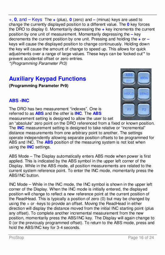
+, 0, and – Keys The + (plus), 0 (zero) and – (minus) keys are used to change the currently displayed position to a different value. The 0 key forces the DRO to display 0. Momentarily depressing the + key increments the current position by one unit of measurement. Momentarily depressing the – key decrements the current position by one unit. Pressing and holding the + or – keys will cause the displayed position to change continuously. Holding down the key will cause the amount of change to speed up. This allows for quick adjustments over a range of large values. These keys can be ‘locked out’* to prevent accidental offset or zero entries. *(Programming Parameter Pr3)
Auxiliary Keypad Functions (Programming Parameter Pr9)
ABS -INC
The DRO has two measurement “indexes”. One is referred to as ABS and the other is INC. The ABS measurement setting is designed to allow the user to set an “absolute“ zero point on the DRO referenced from a fixed or known position. The INC measurement setting is designed to take relative or “incremental” distance measurements from one arbitrary point to another. The settings operate independently allowing separate position offsets to be programmed for ABS and INC. The ABS position of the measuring system is not lost when using the INC settings.
ABS Mode – The Display automatically enters ABS mode when power is first applied. This is indicated by the ABS symbol in the upper left corner of the Display. While in the ABS mode, all position measurements are related to the current system reference point. To enter the INC mode, momentarily press the ABS/INC button.
INC Mode – While in the INC mode, the INC symbol is shown in the upper left corner of the Display. When the INC mode is initially entered, the displayed position will change to reflect a new reference point at the current position of the ReadHead. This is typically a position of zero (0) but may be changed by using the + or -keys to provide an offset. Moving the ReadHead in either direction will display the distance moved from the initial INC starting point (plus any offset). To complete another incremental measurement from the new position, momentarily press the ABS/INC key. The Display will again change to 0 (or the previously programmed offset). To return to the ABS mode, press and hold the ABS/INC key for 3-4 seconds.

Accurate Technology Page 17 of 24
MONitor This function is available but rarely used on ProStop systems. Change Programming parameter Pr9 to 7 to enable this unction. The Display has the ability to monitor a measurement position to detect position drift or measurement variance. To activate the monitoring mode, position the ReadHead to the desired location and momentarily press the MON key. The MON symbol will flash on the display to indicate that the position monitor mode is active. If the ReadHead moves outside the programmed tolerance (Pr18) the reading flashes, indicating a drift condition. When the ReadHead is moved back within the programmed tolerance, the displayed reading will stop flashing. To exit the monitor mode, momentarily press the MON key. The MON symbol and the currently displayed position will stop flashing.
NOTE: Monitor mode can only be activated while in the ABS measuring mode. If the ABS/INC key is depressed while monitoring, the position-monitoring mode is automatically exited. The Display can be programmed to automatically enter or exit the MONitor mode based on elapsed time or movement of the ReadHead. If the programmable auto monitor is enabled (Programming Parameter Pr19 set to 1), the Display will automatically enter monitor mode after either 30 or 60 seconds without Jaw movement. If the programmable auto monitor is disabled, the ProScale will automatically exit monitor mode if the ReadHead is moved beyond a programmable distance from the monitored position. This option, in conjunction with auto monitor activation, allows the ProScale to be kept in monitor mode without manually pressing the monitor key. (Programming Parameters 18, 19, 20, 21)
HOLD This function is available but rarely used on ProStop systems. Change Programming parameter Pr9 to 7 to enable this unction. The Display provides a feature that allows the displayed position to be “frozen” in time while the ReadHead is moved from its measuring position. This allows measurements to be captured on the Display and held for later viewing regardless of the current ReadHead position. To activate the HOLD mode, momentarily press the HOLD key. The HOLD symbol will be shown in the upper left corner of the Display. The currently displayed position and selected key presses will be frozen at this point. To release the HOLD feature, momentarily press the HOLD key again, or cycle power.

ProStop Page 18 of 24
SEND The DRO provides an output port that can be used to send measurement information to a compatible SPC device such as a printer or data acquisition unit. After connecting the SPC device to the 10 pin connector on the DRO, the user may initiate the data transmission by momentarily pressing the SEND key. This signals the SPC device to acquire the data from the DRO. Pressing the SEND key displays “ Snd ” on the LCD for 1 second to show activation of the send function (even if no SPC device is attached to the DRO). The data format and connector style of the DRO SPC output is the same as Mitutoyo (Digimatic®) SPC. This is an industry standard that can be interfaced with most available SPC products including multiplexers, RS232 converters and PC plug-in boards. Data from the DRO is sent to the SPC connector in either millimeters or decimal inches, whichever is currently displayed on the LCD. If no SPC device is attached to the DRO, the SEND key has no other function.
F1 F1 is used for OFFSET ADDITION. Pressing F1 will cycle through 4 independent offsets of which 3 are user programmable (Pr11, 12 & 13). 1. 1. Absolute Reading 2. 2. Absolute Reading + Value programmed in Pr11 3. 3. Absolute Reading + Value programmed in Pr12 4. 4. Absolute Reading + Value programmed in Pr13 F2 Not used on ProStop Systems.

Accurate Technology Page 19 of 24
Display Functions
Lock Mode The user can “lock-out” the position offset adjustment functions (+, 0, -keys) to prevent accidental changes of the current displayed position. To activate the lock mode, press and hold the ON/OFF key and then momentarily press the MODE key. The word LOCK on the LCD Display will turn on or off with eac h lock/unlock operation. When the LOCK symbol is displayed, the +, 0, and keys will not change the displayed position. ABS and INC modes have independent lock operations. (Programming Parameter Pr3)
Offset Addition Offset addition allows the user to preset up to 3 different values that are added to the DRO reading when selected. This function allows the user to quickly switch from one reference point to another. This is especially useful for storing different offsets associated with different blades (kerfs). To utilize the offset addition feature, programming parameter Pr10 must be set to 1. The DRO will then flash one of “offset” numerals 1, 2, 3 or 4 located in the upper left corner of the LCD. Offset 1 is the ABS position with no offset value added. Offset 2 is the ABS position with parameter Pr11 (Offset Addition 2) added to it. Offsets 3 and 4 have similar functions with parameters Pr12 and Pr13 added to the ABS position respectively. To move from Offset 1 to 2, momentarily press the F1 key. Each depression of the F1 key advances to the next offset. After offset 4, the Display will move back to offset 1. (Programming Parameters 10, 11, 12 and 13)
Limit Mode This function is available but rarely used on ProStop systems. The DRO will show either “LL“ for Lower Limit or ”UL” for Upper Limit if a pre-programmed upper or lower reading is encountered. Upper and Lower Limits are set with Programming Parameters Pr16 and Pr17 but are only active if Pr14 is set to 1. The readout toggles for 2 seconds between current positio n display and "LL" or "UL". This continues as long as limit is exceeded. (Programming Parameters 14, 16 and 17)
Scaling All ProStop DROs have the ability to “scale” the actual measurement. This function is useful when the actual measurement must be multiplied or divided before being displayed. Care should be taken when using this function since invoking it will cause the unit to display a reading different than the actual measured value.(Programming Parameter Pr7)

ProStop Page 20 of 24
Jumpers Although the ProStop Display uses a keyboard-programming method to enable and configure features in the unit, several selection jumpers are located on the circuit board for additional system configuration. User configurable jumpers consist of three pins and a ‘shorting block’. The center of these pins is ‘Common’. One end pin is labeled ‘A’ and the other end pin is labeled ‘B’.
JP1 FOR FACTORY USE ONLY
JP2 Product Selection All ProStops are factory set to position B
JP3 Programming Enable/Disable Front panel entry to the programming mode of the DRO can be enabled or disabled. To enable programming (default), install the shorting jumper in position A. To disable programming, install in position B. When programming mode is disabled, the user cannot access the programming functions via the Mode + 0 keys as described in the Section 4: PROGRAMMING. This provides the user with a method of configuring the DRO with specific parameters and prevents unauthorized configuration changes.
JP4 DRO Type All ProStops are factory set to position B
JP5 Battery Selection FACTORY SETTING ONLY – Do Not Change.

Accurate Technology Page 21 of 24
Programming Summary The following settings apply to ProStop Display Serial # ____________
Factory Parameter Function Default This System Pr0 Reading Direction 0 Pr1 Segment Offset 1 -On 0 – Off Pr2 High Speed ReadHead 0 -Off Pr3 Zero, Offset Entry 1 – Enable Pr4 Display Resolution 1 -Normal Pr5 mm or cm 0 -mm Pr6 Fractions, mm, in 0 -all Pr7 Scaling 1.0000 (none) Pr8 Auto off 15 -15 min. Pr9 Auxiliary Keypad 7 -all keys ___1__ Pr10 Offset Addition 0 -disabled Pr11 Offset Addition 1 1.000 Inch Pr12 Offset Addition 2 1.500 Inch Pr13 Offset Addition 3 2.000 Inch Pr14 Output Mode 0 -drift Pr15 Output Polarity 0 – Normally Open Pr16 Lower Limit 0.000 Pr17 Upper Limit 5.000 Inch Pr18 Drift Tolerance .010 Inch Pr19 Auto Monitor ON 0 -disabled Pr20 Auto Monitor OFF 0 -disabled Pr21 Auto Monitor Distance .500 Inch Pr22 Backlight On 4 -Always Pr23 FUTURE FEATURE 1 Pr24 RF Display Address 0 – Off Pr25 RF System ID 0 Pr26 Noise Suppression 0 – Minimum Pr27 Accuracy Comp. Enable 1 – ON Pr28 Compensation Multiple 5 – 5 in. Programming Parameters that do not apply to ProStops are shown in Gray. Programming Parameters specific to ProStop are shown highlighted.
Pressing and holding the ON/OFF key and MODE key for 10 seconds with power off will perform a full segment LCD test AND set all Programming Parameters to factory defaults. ALL ProStop specific settings will be lost.
Printed Circuit Board Jumper Information: JP1 Factory Use Only Do Not Change JP2 Position B for ProStop Do Not Change JP3 Programming Enable/Disable User Selectable JP4 Position B for ProPanel Do Not Change JP5 Battery Selection Factory ONLY

ProStop Page 22 of 24
Key Press Function Summary How long a key is depressed, and the combination of the keys pressed is important. The term (Momentarily) describes a key press of typically less than 1 second. Whereas (Press & Hold) is used to imply a key press of typically longer than 1.5 seconds. For example: When using a PC keyboard to type a CAPITAL letter you would “press and hold” the SHIFT key and “momentarily” depress the LETTER key. In addition, a key(s) “function” is executed on the key RELEASE, not the key DEPRESS of that key(s). This is important since some keys execute different functions based on how long they are depressed. These key operations, once tried, quickly become intuitive.
ON/OFF (Momentarily) RESULT: Turn Display power on or off.
ON/OFF (Press & Hold) for 5 seconds RESULT: Display Battery Voltage.
ON/OFF (Press & Hold) + MODE (Momentarily) RESULT: Enable/Disable LOCK mode.
ON/OFF + MODE (Press & Hold Both keys) for 10 seconds (display off) RESULT: LCD Segment Test & reset to factory defaults
MODE (Press & Hold) + ‘0’(Momentarily) RESULT: Enter or Exit Programming Mode.
While in Programming mode:
MODE (Momentarily) RESULT: Advances the Programming Parameter list.
ON/OFF (Press & Hold) + MODE (Momentarily) RESULT: Step Programming Parameter list backwards.
+(Momentarily) while displaying a Programming Parameter RESULT: Increases Programming Parameter setting.
-(Momentarily) while displaying a Programming Parameter RESULT: Decreases Programming Parameter setting.
0 (Momentarily) while displaying a Programming Parameter RESULT: Sets Programming Parameter to Default.
Accurate Technology Page 23 of 24
SECTION 5 MISCELLANEOUS
Frequently Asked Questions What does “no Enc” mean?
If the Encoder is off the Scale, or the Encoder cable is unplugged from the DRO, a “no Enc” will appear on the LCD. To clear error:
1. Be sure the Encoder is on the Scale. 2. Unplug the connector from the DRO for one second. 3. Reconnect the Encoder cable to the DRO. The battery clips seem to be very loose. Is this normal?
YES! DO NOT attempt to bend these clips or wedge anything between them and the case. These clips are designed to expand when the two case halves are screwed together.
The LCD does not change, or changes very little, as the Stop moves. 1. 1. The DRO is in the HOLD mode. Press & release the Hold button. 2. 2. The Scaling factor is set very low. Reset to 1.0000 (Pr7)

ProStop Page 24 of 24
Thank you for choosing a ProScale Product
MADE IN USA
Accurate Technology, Inc. 270 Rutledge Rd. Unit E Fletcher, NC 28732
USA 800 233-0580 • 828-654-7920 Fax 828-654-8824 www.proscale.com
This manual is available at www.proscale.com
Please return your Product Registration Card or register your system at:
www.proscale.com/registration.htm