Embed Size (px)
Citation preview
Digital readouts
for milling machines and boring mills
for lathes
for general purpose applications and grinders
for milling machines and boring mills
for lathes
for general purpose applications and grinders
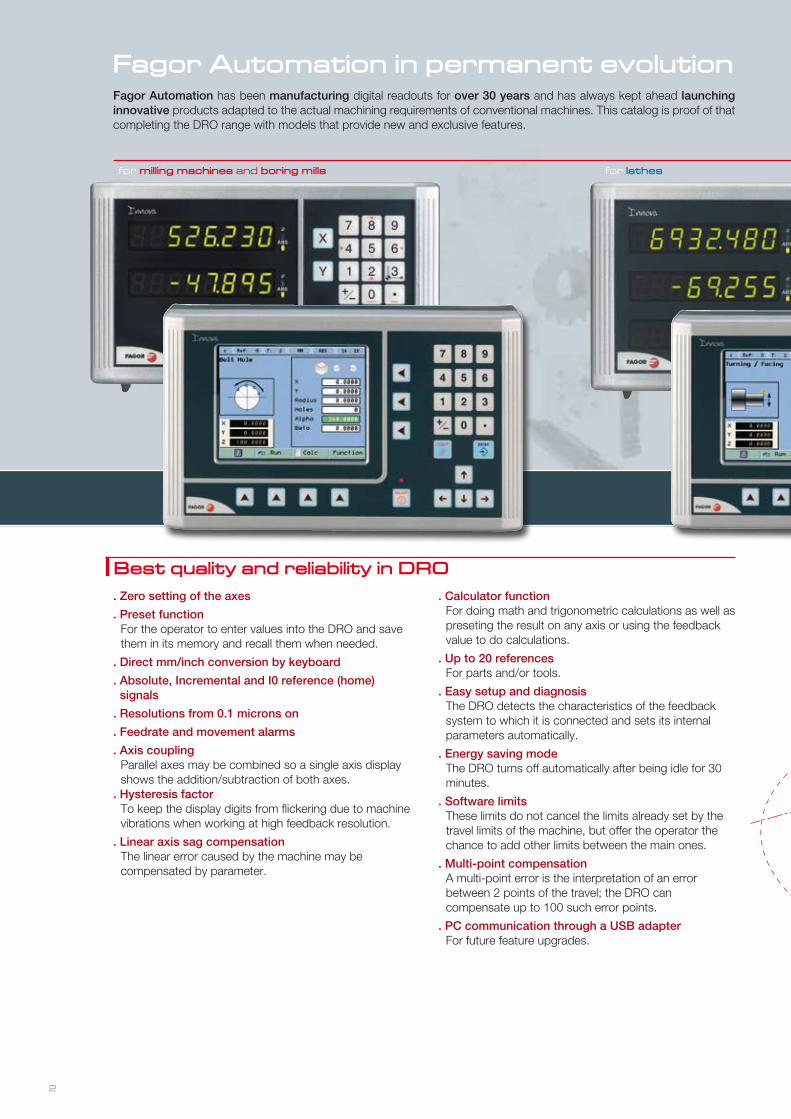
Fagor Automation in permanent evolution
Best quality and reliability in DRO
Fagor Automation has been manufacturing digital readouts for over 30 years and has always kept ahead launching innovative products adapted to the actual machining requirements of conventional machines. This catalog is proof of that completing the DRO range with models that provide new and exclusive features.
2
. Calculator functionFor doing math and trigonometric calculations as well as preseting the result on any axis or using the feedback value to do calculations.
. Up to 20 referencesFor parts and/or tools.
. Easy setup and diagnosisThe DRO detects the characteristics of the feedback system to which it is connected and sets its internal parameters automatically.
. Energy saving modeThe DRO turns off automatically after being idle for 30 minutes.
. Software limitsThese limits do not cancel the limits already set by the travel limits of the machine, but offer the operator the chance to add other limits between the main ones.
. Multi-point compensationA multi-point error is the interpretation of an error between 2 points of the travel; the DRO can compensate up to 100 such error points.
. PC communication through a USB adapterFor future feature upgrades.
. Zero setting of the axes
. Preset functionFor the operator to enter values into the DRO and save them in its memory and recall them when needed.
. Direct mm/inch conversion by keyboard
. Absolute, Incremental and I0 reference (home) signals
. Resolutions from 0.1 microns on
. Feedrate and movement alarms
. Axis couplingParallel axes may be combined so a single axis display shows the addition/subtraction of both axes.
. Hysteresis factorTo keep the display digits from flickering due to machine vibrations when working at high feedback resolution.
. Linear axis sag compensationThe linear error caused by the machine may be compensated by parameter.
for milling machines and boring mills for lathes
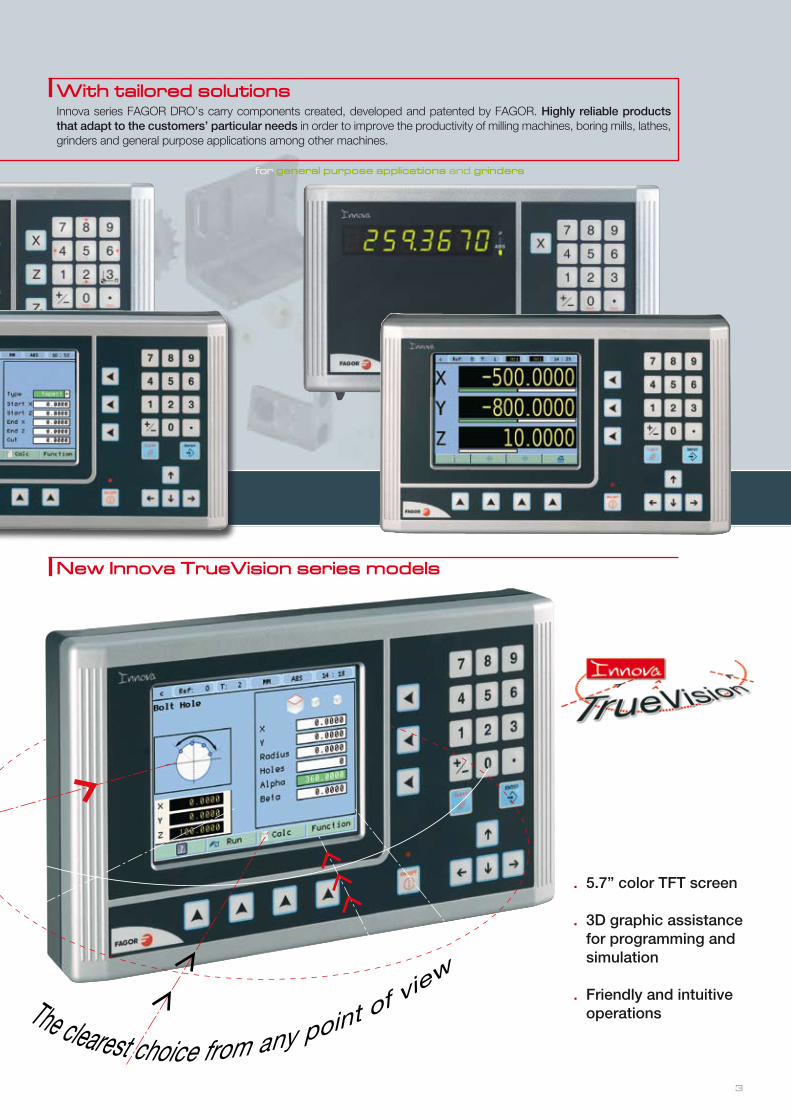
New Innova TrueVision series models
3
With tailored solutionsInnova series FAGOR DRO’s carry components created, developed and patented by FAGOR. Highly reliable products that adapt to the customers’ particular needs in order to improve the productivity of milling machines, boring mills, lathes, grinders and general purpose applications among other machines.
for general purpose applications and grinders
. 5.7” color TFT screen
. 3D graphic assistance for programming and simulation
. Friendly and intuitive operations
the combination that sets it apart
F A G O R D R O ’ s a n d f e e d b a c k s y s t e m s
for milling machines and boring mills for lathes
for general purpose applications and
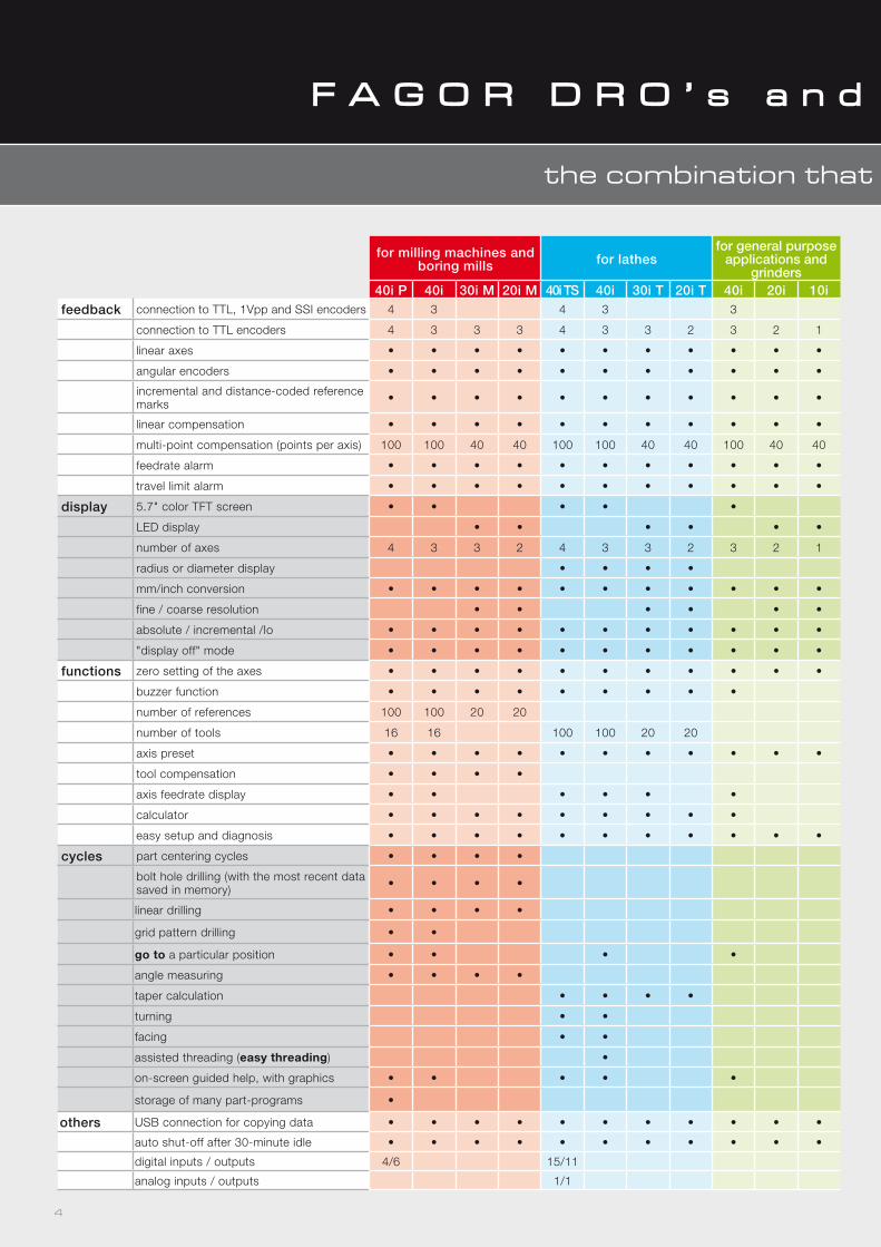
grinders40i P 40i 30i M 20i M 40i TS 40i 30i T 20i T 40i 20i 10i
feedback connection to TTL, 1Vpp and SSI encoders 4 3 4 3 3
connection to TTL encoders 4 3 3 3 4 3 3 2 3 2 1
linear axes • • • • • • • • • • •
angular encoders • • • • • • • • • • •
incremental and distance-coded reference marks • • • • • • • • • • •
linear compensation • • • • • • • • • • •
multi-point compensation (points per axis) 100 100 40 40 100 100 40 40 100 40 40
feedrate alarm • • • • • • • • • • •
travel limit alarm • • • • • • • • • • •
display 5.7" color TFT screen • • • • •
LED display • • • • • •
number of axes 4 3 3 2 4 3 3 2 3 2 1
radius or diameter display • • • •
mm/inch conversion • • • • • • • • • • •
fine / coarse resolution • • • • • •
absolute / incremental /Io • • • • • • • • • • •
"display off" mode • • • • • • • • • • •
functions zero setting of the axes • • • • • • • • • • •
buzzer function • • • • • • • • •
number of references 100 100 20 20
number of tools 16 16 100 100 20 20
axis preset • • • • • • • • • • •
tool compensation • • • •
axis feedrate display • • • • • •
calculator • • • • • • • • •
easy setup and diagnosis • • • • • • • • • • •
cycles part centering cycles • • • •
bolt hole drilling (with the most recent data saved in memory) • • • •
linear drilling • • • •
grid pattern drilling • •
go to a particular position • • • •
angle measuring • • • •
taper calculation • • • •
turning • •
facing • •
assisted threading (easy threading) •
on-screen guided help, with graphics • • • • •
storage of many part-programs •
others USB connection for copying data • • • • • • • • • • •
auto shut-off after 30-minute idle • • • • • • • • • • •
digital inputs / outputs 4/6 15/11
analog inputs / outputs 1/1
4
the combination that sets it apart
F A G O R D R O ’ s a n d f e e d b a c k s y s t e m s
Linear encoders for conventional machines
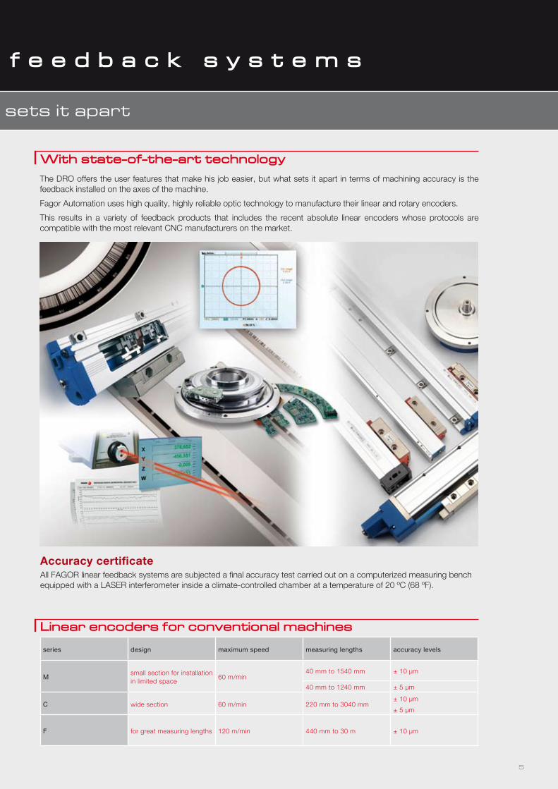
With state-of-the-art technologyThe DRO offers the user features that make his job easier, but what sets it apart in terms of machining accuracy is the feedback installed on the axes of the machine.
Fagor Automation uses high quality, highly reliable optic technology to manufacture their linear and rotary encoders.
This results in a variety of feedback products that includes the recent absolute linear encoders whose protocols are compatible with the most relevant CNC manufacturers on the market.
series design maximum speed measuring lengths accuracy levels
Msmall section for installation in limited space
60 m/min40 mm to 1540 mm ± 10 µm
40 mm to 1240 mm ± 5 µm
C wide section 60 m/min 220 mm to 3040 mm± 10 µm
± 5 µm
F for great measuring lengths 120 m/min 440 mm to 30 m ± 10 µm
Accuracy certificateAll FAGOR linear feedback systems are subjected a final accuracy test carried out on a computerized measuring bench equipped with a LASER interferometer inside a climate-controlled chamber at a temperature of 20 ºC (68 ºF).
5
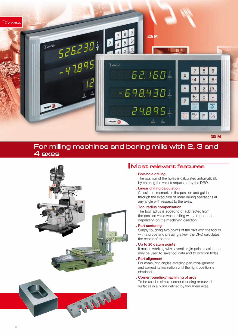
For milling machines and boring mills with 2, 3 and 4 axes
Most relevant features. Bolt-hole drillingThe position of the holes is calculated automatically by entering the values requested by the DRO.
. Linear drilling calculationCalculates, memorizes the position and guides through the execution of linear drilling operations at any angle with respect to the axes.
. Tool radius compensationThe tool radius is added to or subtracted from the position value when milling with a round tool depending on the machining direction.
. Part centeringSimply touching two points of the part with the tool or with a probe and pressing a key, the DRO calculates the center of the part.
. Up to 20 datum pointsIt makes working with several origin points easier and may be used to save tool data and to position holes
. Part alignmentFor measuring angles avoiding part misalignment and correct its inclination until the right position is obtained.
. Corner rounding/machining of arcsTo be used in simple corner rounding or curved surfaces in a plane defined by two linear axes.
6
20i M
30i M
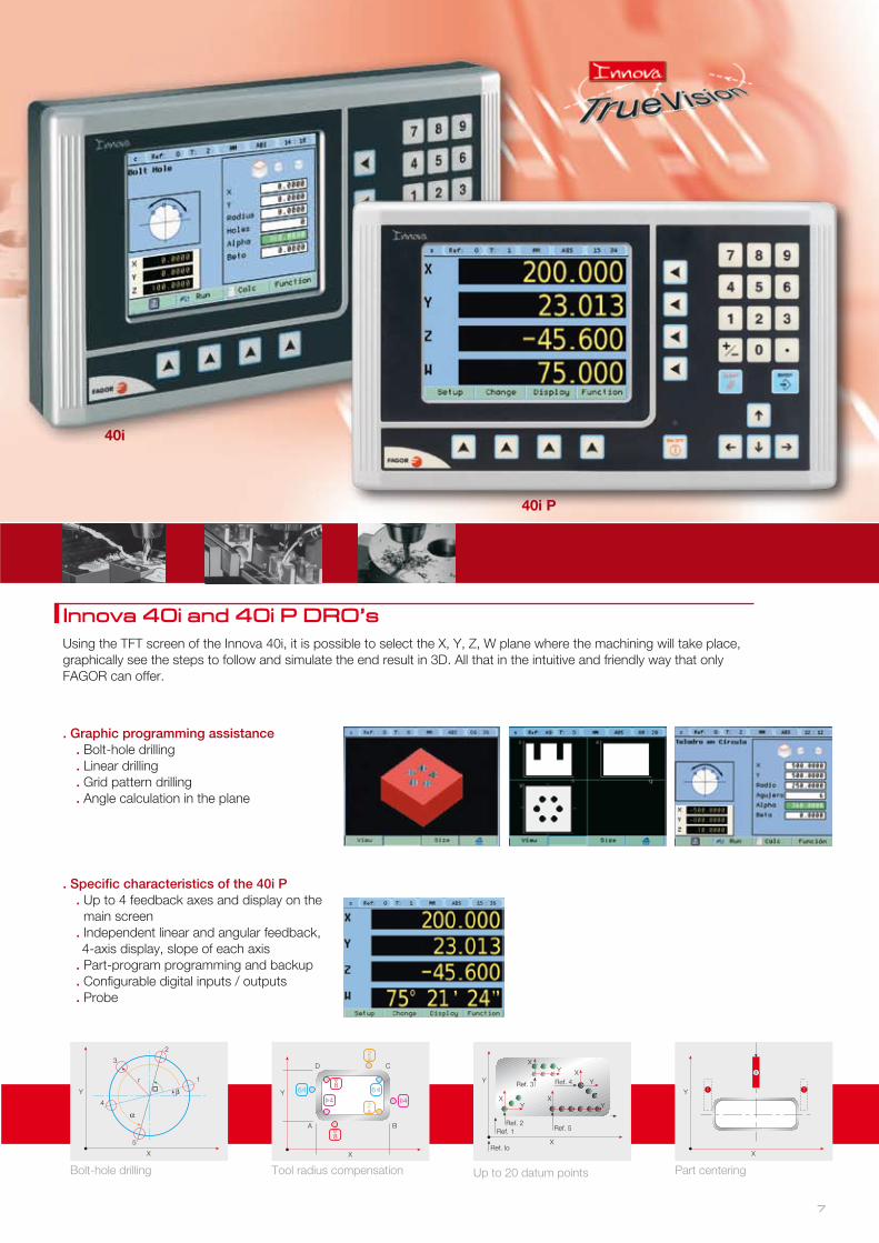
Most relevant features Innova 40i and 40i P DRO’sUsing the TFT screen of the Innova 40i, it is possible to select the X, Y, Z, W plane where the machining will take place, graphically see the steps to follow and simulate the end result in 3D. All that in the intuitive and friendly way that only FAGOR can offer.
. Graphic programming assistance. Bolt-hole drilling. Linear drilling. Grid pattern drilling. Angle calculation in the plane
. Specific characteristics of the 40i P. Up to 4 feedback axes and display on the main screen
. Independent linear and angular feedback, 4-axis display, slope of each axis
. Part-program programming and backup
. Configurable digital inputs / outputs
. Probe
Y
X
r
4
3
2
1
5
�
Bolt-hole drilling
XY
XY X
Y
XY
Ref. 2Ref. 1
Ref. Io
Ref. 3 Ref. 4
Ref. 5
Y
X
Up to 20 datum points
Y
X
1 2
3
Part centering
8
4
8
4
6 6
2
2
A B
CD
Y
X
Tool radius compensation
7
40i
40i P
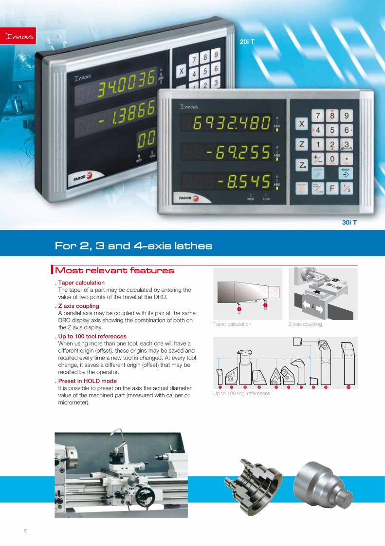
For 2, 3 and 4-axis lathes
Most relevant features. Taper calculationThe taper of a part may be calculated by entering the value of two points of the travel at the DRO.
. Z axis couplingA parallel axis may be coupled with its pair at the same DRO display axis showing the combination of both on the Z axis display.
. Up to 100 tool referencesWhen using more than one tool, each one will have a different origin (offset), these origins may be saved and recalled every time a new tool is changed. At every tool change, it saves a different origin (offset) that may be recalled by the operator.
. Preset in HOLD modeIt is possible to preset on the axis the actual diameter value of the machined part (measured with caliper or micrometer).
Taper calculation Z axis coupling
21 Z1
XZ2
X
Z
1 2 3 4 5 6 7 8 9 100...
Up to 100 tool references
8
20i T
30i T 40i TS
40i
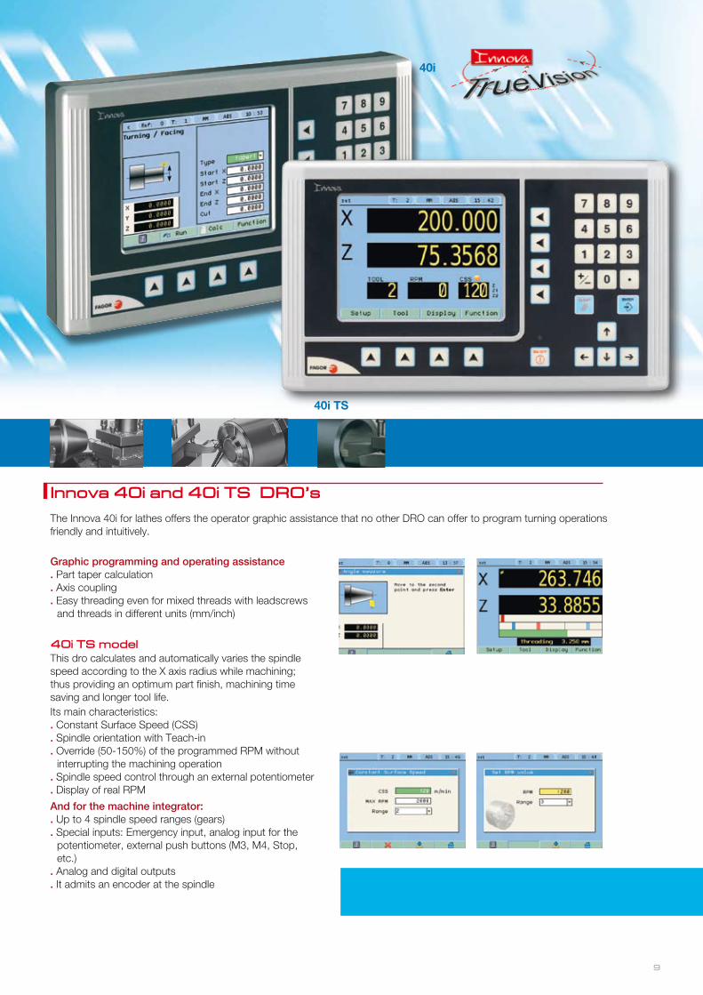
Innova 40i and 40i TS DRO’s
The Innova 40i for lathes offers the operator graphic assistance that no other DRO can offer to program turning operations friendly and intuitively.
Its main characteristics:. Constant Surface Speed (CSS). Spindle orientation with Teach-in. Override (50-150%) of the programmed RPM without
interrupting the machining operation. Spindle speed control through an external potentiometer. Display of real RPM
And for the machine integrator:. Up to 4 spindle speed ranges (gears). Special inputs: Emergency input, analog input for the
potentiometer, external push buttons (M3, M4, Stop, etc.)
. Analog and digital outputs
. It admits an encoder at the spindle
Graphic programming and operating assistance. Part taper calculation. Axis coupling. Easy threading even for mixed threads with leadscrews
and threads in different units (mm/inch)
40i TS modelThis dro calculates and automatically varies the spindle speed according to the X axis radius while machining; thus providing an optimum part finish, machining time saving and longer tool life.
9
20i T
30i T 40i TS
40i
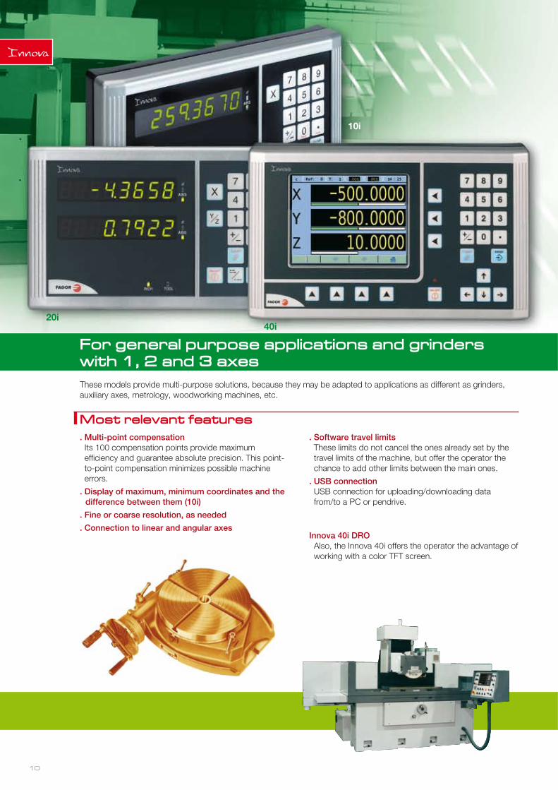
For general purpose applications and grinders with 1, 2 and 3 axes
Most relevant features. Multi-point compensationIts 100 compensation points provide maximum efficiency and guarantee absolute precision. This point-to-point compensation minimizes possible machine errors.
. Display of maximum, minimum coordinates and the difference between them (10i)
. Fine or coarse resolution, as needed
. Connection to linear and angular axes
. Software travel limitsThese limits do not cancel the ones already set by the travel limits of the machine, but offer the operator the chance to add other limits between the main ones.
. USB connectionUSB connection for uploading/downloading data from/to a PC or pendrive.
Innova 40i DROAlso, the Innova 40i offers the operator the advantage of working with a color TFT screen.
These models provide multi-purpose solutions, because they may be adapted to applications as different as grinders, auxiliary axes, metrology, woodworking machines, etc.
10
10i
20i 40i
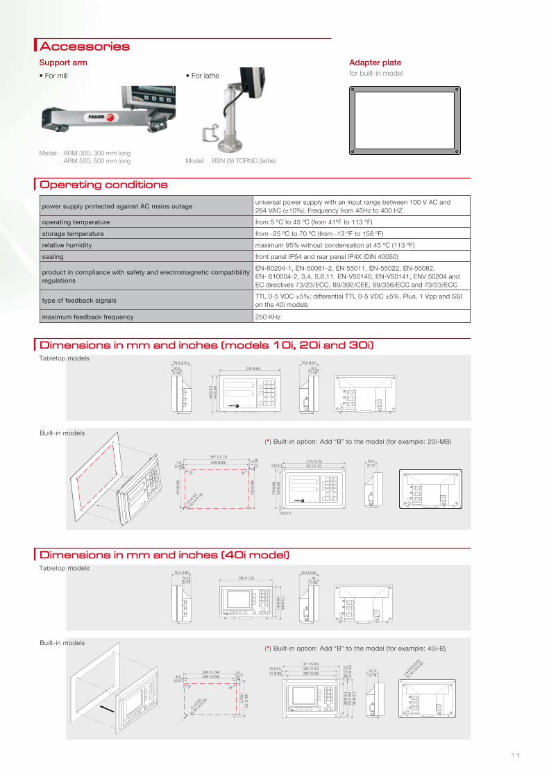
AccessoriesSupport arm
• For mill • For lathe
Model: . ARM 300, 300 mm long . ARM 500, 500 mm long Model: . BSN 09 TORNO (lathe)
Adapter platefor built-in model
Dimensions in mm and inches (models 10i, 20i and 30i)
Dimensions in mm and inches (40i model)
Operating conditions
power supply protected against AC mains outageuniversal power supply with an input range between 100 V AC and 264 VAC (±10%); Frequency from 45Hz to 400 HZ
operating temperature from 5 ºC to 45 ºC (from 41ºF to 113 ºF)
storage temperature from -25 ºC to 70 ºC (from -13 ºF to 158 ºF)
relative humidity maximum 95% without condensation at 45 ºC (113 ºF)
sealing front panel IP54 and rear panel IP4X (DIN 40050)
product in compliance with safety and electromagnetic compatibility regulations
EN-60204-1, EN-50081-2, EN 55011, EN-55022, EN-55082, EN- 610004-2, 3,4, 5,6,11. EN-V50140, EN-V50141, ENV 50204 and EC directives 73/23/ECC, 89/392/CEE, 89/336/ECC and 73/23/ECC
type of feedback signalsTTL 0-5 VDC ±5%; differential TTL 0-5 VDC ±5%. Plus, 1 Vpp and SSI on the 40i models
maximum feedback frequency 250 KHz
Tabletop models
Tabletop models
Built-in models
Built-in models
(*) Built-in option: Add “B” to the model (for example: 20i-MB)
(*) Built-in option: Add “B” to the model (for example: 40i-B)
11
Fagor Automation S. Coop.
Bº San Andrés, 19 – P.O.Box 144E-20500 Arrasate-Mondragón, SpainTel. 34 943 719 200 34 943 039 800Fax: 34 943 791 712E-mail: [email protected]
AMERICA
BR - Fagor Automation do Brasil Com. Imp. Exp. Ltda. (São Paulo) Tel. 55 11 56 94 08 22 Fax: 55 11 56 81 62 71 CA - Fagor Automation Ontario (Mississauga) Tel. 1 905 670 74 48 Fax: 1 905 670 74 49
Fagor Automation Quebec (Montreal) Tel. 1 450 227 05 88 Fax: 1 450 227 61 32
Fagor Automation Windsor (Canada) Tel. 1 519 944 56 74 Fax: 1 519 944 23 69
US - Fagor Automation Corp. (Chicago) Tel. 1 847 98 11 500 Fax: 1 847 98 11 311
Fagor Automation West Coast (California) Tel. 1 714 957 98 85 Fax: 1 714 957 98 91
Fagor Automation East Coast (New Jersey) Tel. 1 973 773 35 25 Fax: 1 973 773 35 26
Fagor Automation Texas (Houston) Tel. 1 281 463 39 15 Fax. 1 281 463 39 19
Fagor Automation South East (Florida) Tel. 1 813 654 45 99 Fax: 1 813 654 3387
Fagor Automation holds the ISO 9001 Quality System Certificate as well as the CE and UL certificates for its digital readouts.
ER-073/1994
ASIA
CN - Beijing Fagor Automation Equipment Co., Ltd. (Beijing) Tel. 86 10 84505858 Fax: 86 10 84505860
Beijing Fagor Automation Equipment Ltd. (Nanjing) Tel. 86 25 83 32 82 59 Fax: 86 25 83 32 82 60
Beijing Fagor Automation Equipment Ltd. (Chengdu) Tel. 86 28 66 13 20 81 Fax. 86 28 66 13 20 82
Beijing Fagor Automation Equipment Co., Ltd. (Guangzhou) Tel. 86 20 86 55 31 24 Fax: 86 20 86 55 31 25
Beijing Fagor Automation Equipment Co., Ltd. (Shanghai) Tel. 86 21 63 53 90 07 Fax: 86 21 63 53 88 40
HK - Fagor Automation (Asia) Ltd., (Hong Kong) Tel. 852 23 89 16 63 Fax: 852 23 89 50 86
IN - Fagor Control Systems Pvt. Ltd. (Bangalore) Tel. +91 (0)8042682828 Fax: +91 (0)8042682816
KR - Fagor Automation Korea, Ltd. (Seoul) Tel. 82 2 21 13 03 41 / 2113 0342 Fax: 82 2 21 13 03 43
MY - Fagor Automation (M) SDN.BHD. (Kuala Lumpur) Tel. 60 3 8062 2858 Fax: 60 3 8062 3858
SG - Fagor Automation (S) Pte. Ltd. (Singapore) Tel. 65 68417345 / 68417346 Fax: 65 68417348
TW - Fagor Automation Taiwan Co. Ltd. (Taichung) Tel. 886 4 2 385 1558 Fax: 886 4 2 385 1598
EUROPE
DE - Fagor Automation GmbH (Göppingen) Tel. 49 7161 15 6850 Fax: 49 7161 15 685 79
ES - Fagor Automation Catalunya (Barcelona) Tel. 34 934 744 375 Fax: 34 934 744 327
FR - Fagor Automation France S.à.r.l. (Clermont Ferrand) Tel. 33 473 277 916 Fax: 33 473 150 289
GB - Fagor Automation UK Ltd. (West Midlands) Tel. 44 1327 300 067 Fax: 44 1327 300 880
IT - Fagor Italia S.R.L. (Milano) Tel. 39 0295 301 290 Fax: 39 0295 301 298 PO - Fagor Automation Ltda. (Leça da Palmeira) Tel. 351 229 968 865 Fax: 351 229 960 719
RU - Fagor Automation Russia. (Moscow) Tel. 7 4966 161 895
Worldwide reliability
EU
SK
OP
I
DR
O -
EN
090
9
FAGOR AUTOMATION shall not be responsible for any printing or transcribing errors in the catalog and reserves the right to make changes to the characteristics of its products without prior notice.