Embed Size (px)
Citation preview
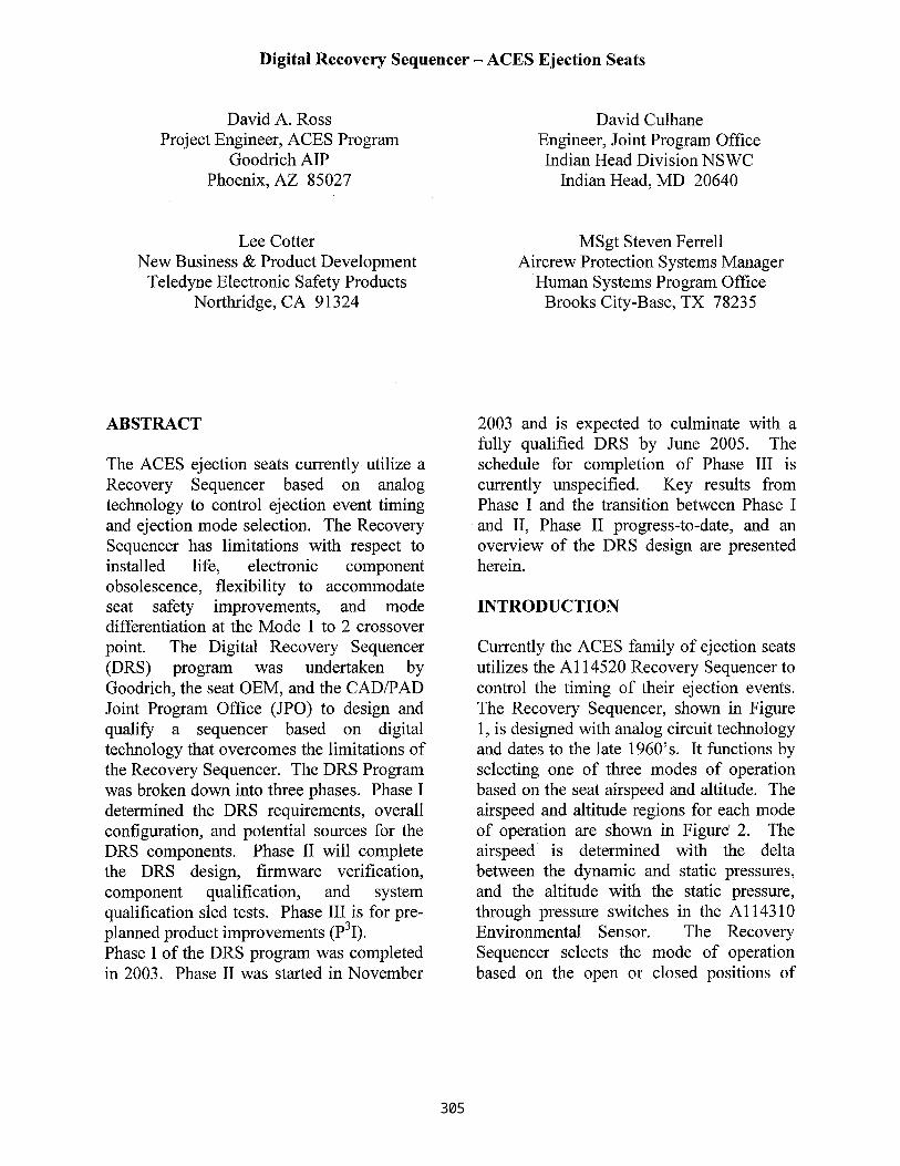
Digital Recovery Sequencer- ACES Ejection Seats
David A. Ross Project Engineer, ACES Program
Goodrich AIP Phoenix, AZ 85027
David Culhane Engineer, Joint Program Office Indian Head Division NSWC
Indian Head, MD 20640
LeeCotter New Business & Product Development
Teledyne Electronic Safety Products Northridge, CA 91324
MSgt Steven Ferrell Aircrew Protection Systems Manager
Human Systems Program Office Brooks City-Base, TX 78235
ABSTRACT
The ACES ejection seats currently utilize a Recovery Sequencer based on analog technology to control ejection event timing and ejection mode selection. The Recovery Sequencer has limitations with respect to installed life, electronic component obsolescence, flexibility to accommodate seat safety improvements, and mode differentiation at the Mode 1 to 2 crossover point. The Digital Recovery Sequencer (DRS) program was undertaken by Goodrich, the seat OEM, and the CAD/PAD Joint Program Office (JPO) to design and qualify a sequencer based on digital technology that overcomes the limitations of the Recovery Sequencer. The DRS Program was broken down into three phases. Phase I determined the DRS requirements, overall configuration, and potential sources for the DRS components. Phase II will complete the DRS design, firmware verification, component qualification, and system qualification sled tests. Phase III is for pre- planned product improvements (p3I). Phase I of the DRS program was completed in 2003. Phase II was started in November
2003 and is expected to culminate with a fully qualified DRS by June 2005. The schedule for completion of Phase III is currently unspecified. Key results from Phase I and the transition between Phase I and II, Phase II progress-to-date, and an overview of the DRS design are presented herein.
INTRODUCTION
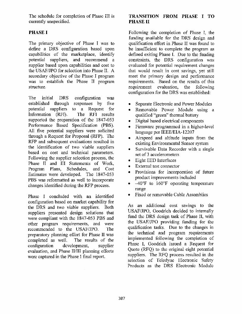
Currently the ACES family of ejection seats utilizes the A114520 Recovery Sequencer to control the timing of their ejection events. The Recovery Sequencer, shown in Figure 1, is designed with analog circuit technology and dates to the late 1960's. It functions by selecting one of three modes of operation based on the seat airspeed and altitude. The airspeed and altitude regions for each mode of operation are shown in Figur6 2. The airspeed ~ is determined with the delta between the dynamic and static pressures, and the altitude with the static pressure, through pressure switches in the A114310 Environmental Sensor. The Recovery Sequencer selects the mode of operation based on the open or closed positions of
Page 1
Report Documentation Page Form ApprovedOMB No. 0704-0188
Public reporting burden for the collection of information is estimated to average 1 hour per response, including the time for reviewing instructions, searching existing data sources, gathering andmaintaining the data needed, and completing and reviewing the collection of information. Send comments regarding this burden estimate or any other aspect of this collection of information,including suggestions for reducing this burden, to Washington Headquarters Services, Directorate for Information Operations and Reports, 1215 Jefferson Davis Highway, Suite 1204, ArlingtonVA 22202-4302. Respondents should be aware that notwithstanding any other provision of law, no person shall be subject to a penalty for failing to comply with a collection of information if itdoes not display a currently valid OMB control number.
1. REPORT DATE SEP 2004
2. REPORT TYPE N/A
3. DATES COVERED -
4. TITLE AND SUBTITLE Digital Recovery Sequencer - ACES Ejection Seats
5a. CONTRACT NUMBER
5b. GRANT NUMBER
5c. PROGRAM ELEMENT NUMBER
6. AUTHOR(S) 5d. PROJECT NUMBER
5e. TASK NUMBER
5f. WORK UNIT NUMBER
7. PERFORMING ORGANIZATION NAME(S) AND ADDRESS(ES) Goodrich AIP David A. Ross Phoenix, AZ 85027
8. PERFORMING ORGANIZATIONREPORT NUMBER
9. SPONSORING/MONITORING AGENCY NAME(S) AND ADDRESS(ES) 10. SPONSOR/MONITOR’S ACRONYM(S)
11. SPONSOR/MONITOR’S REPORT NUMBER(S)
12. DISTRIBUTION/AVAILABILITY STATEMENT Approved for public release, distribution unlimited
13. SUPPLEMENTARY NOTES Published in the Proceedings of the Forty Second Annual SAFE Association Symposium, Held in the SaltLake City, Utah, September 27-28, 2004. SAFE Association, Post Office Box 130, Creswell, OR 97426-0130.http://www.safeassociation.org. , The original document contains color images.
14. ABSTRACT
15. SUBJECT TERMS
16. SECURITY CLASSIFICATION OF: 17. LIMITATION OF ABSTRACT
SAR
18. NUMBEROF PAGES
8
19a. NAME OFRESPONSIBLE PERSON
a. REPORT unclassified
b. ABSTRACT unclassified
c. THIS PAGE unclassified
Standard Form 298 (Rev. 8-98) Prescribed by ANSI Std Z39-18
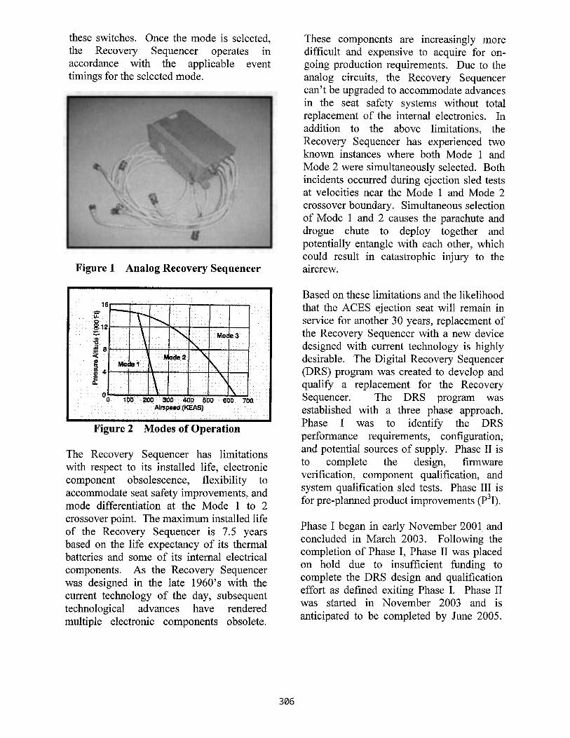
these switches. Once the mode is selected, the Recovery Sequencer operates in accordance with the applicable event timings for the selected mode.
Figure 1 Analog Recovery Sequencer
• " . . . . : ~ i ' ¸ . : . . . . / i
" 1 . 6 : - - - " - - ~ " . , - . ~ . : i : . . . . . ,,. ,_ . •
¸. .... . i :
0 100 200 300 400 500 600 700 A i m ~ ! ( K ~ S ) :
. . . . . . . . . . . . . . . , . . , = , . . .
Figure 2 Modes of Operation
The Recovery Sequencer has limitations with respect to its installed life, electronic component obsolescence, flexibility to accommodate seat safety improvements, and mode differentiation at the Mode 1 to 2 crossover point. The maximum installed life of the Recovery Sequencer is 7.5 years based on the life expectancy of its thermal batteries and some of its internal electrical components. As the Recovery Sequencer was designed in the late 1960's with the current technology of the day, subsequent technological advances have rendered multiple electronic components obsolete.
These components are increasingly more difficult and expensive to acquire for on- going production requirements. Due to the analog circuits, the Recovery Sequencer can't be upgraded to accommodate advances in the seat safety systems without total replacement of the internal electronics. In addition to the above limitations, the Recovery Sequencer has experienced two known instances where both Mode 1 and Mode 2 were simultaneously selected. Both incidents occurred during ejection sled tests at velocities near the Mode 1 and Mode 2 crossover boundary. Simultaneous selection of Mode 1 and 2 causes the parachute and drogue chute to deploy together and potentially entangle with each other, which could result in catastrophic injury to the aircrew.
Based on these limitations and the likelihood that the ACES ejection seat will remain in service for another 30 years, replacement of the Recovery Sequencer with a new device designed with current technology is highly desirable. The Digital Recovery Sequencer (DRS) program was created to develop and qualify a replacement for the Recovery Sequencer. The DRS program was established with a three phase approach. Phase I was to identify the DRS performance requirements, configuration, and potential sources of supply. Phase II is to complete the design, firmware verification, component qualification, and system qualification sled tests. Phase III is for pre-planned product improvements (p3I).
Phase I began in early November 2001 and concluded in March 2003. Following the completion of Phase I, Phase II was placed on hold due to insufficient funding to complete the DRS design and qualification effort as defined exiting Phase I. Phase II was started in November 2003 and is anticipated to be completed by June 2005.
Page 2
The schedule for completion of Phase III is currently unspecified.
TRANSITION F R O M PHASE I TO PHASE II
PHASE I
The primary objective of Phase I was to define a DRS configuration based upon capabilities of the marketplace, identify potential suppliers, and recommend a supplier based upon capabilities and cost to the USAF/JPO for selection into Phase II. A secondary objective of the Phase I program was to establish the Phase II program structure.
The initial DRS configuration was established through responses by five potential suppliers to a Request for Information (RFI). The RFI results supported the preparation of the 1847-053 Performance Based Specification (PBS). All five potential suppliers were sol ici ted through a Request for Proposal (RFP). The RFP and subsequent evaluations resulted in the identification of two viable suppliers based on cost and technical parameters. Following the supplier selection process, the Phase II and III Statements of Work, Program Plans, Schedules, and Cost Estimates were developed. The 1847-053 PBS was reformatted as well to incorporate changes identified during the RFP process.
Phase I concluded with an identified configuration based on market capability for the DRS and two viable suppliers. Both suppliers presented design solutions that were compliant with the 1847-053 PBS and other program requirements, and were recommended to the USAF/JPO. The preparatory planning effort for Phase II was completed as well. The results of the configuration development, supplier evaluation, and Phase II/III planning efforts were captured in the Phase I final report.
Following the completion of Phase I, the funding available for the DRS design and qualification effort in Phase II was found to be insufficient to complete the program as defined exiting Phase I. Due to the funding constraints, the DRS configuration was evaluated for potential requirement changes that would result in cost savings, yet still meet the primary design and performance requirements. Based on the results of this requirement evaluation, the following configuration for the DRS was established:
• Separate Electronic and Power Modules • Removable Power Module using a
qualified "green" thermal battery • Digital based electrical components • Firmware programmed in a higher-level
language per IEEE/EIA-12207 • Airspeed and altitude inputs from the
existing Environmental Sensor system • Survivable Data Recorder with a single
set of 3 accelerometers • Eight EED Interfaces • External test connector • Provisions for incorporation of future
product improvements included • -40°F to 160°F operating temperature
range • Fixed or removable Cable Assemblies
As an additional cost savings to the USAF/JPO, Goodrich decided to internally fund the DRS design task of Phase II, with the USAF/JPO providing funding for the qualification tasks. Due to the changes in the technical and program requirements implemented following the completion of Phase I, Goodrich issued a Request for Quote (RFQ) to the original eight potential suppliers. The RFQ process resulted in the selection of Teledyne Electronic Safety Products as the DRS Electronic Module
Page 3
Supplier. In addition, Goodrich elected to be the supplier for the DRS Power Module with Eagle Picher as the thermal battery supplier.
PHASE II
The objective of Phase II is to design and qualify the DRS for use on the ACES family of ejection seats. The Phase II program was established to achieve this objective through completion of the following major milestones:
• System Requirements Review • Hardware/Firmware Development • Fit-Checks • Critical Design Review • Hardware/Firmware Verification • Component Qualification • System Qualification (Sled Testing)
The System Requirements Review was completed in December 2003. Key outcomes of the SRR were a complete review of the 1847-053 PBS requirements, agreements on the methods of compliance to the requirements, development of the tailored approach for compliance with the IEEE-EIA 12207 software development specification, and establishment of the fit- check and component qualification units.
The Hardware/Firmware development effort was started following the SRR and completed prior to the Critical Design Review. During this period of the Phase II program, the designs of the DRS Electronic and Power Modules were completed. The Electronic Module is a derivative of a qualified and fielded sequencer. The Power Module is based on the MXU-792A/A Battery Pack and uses Eagle Picher's qualified "green" thermal batteries. A technical discussion of the DRS design is included under a separate section.
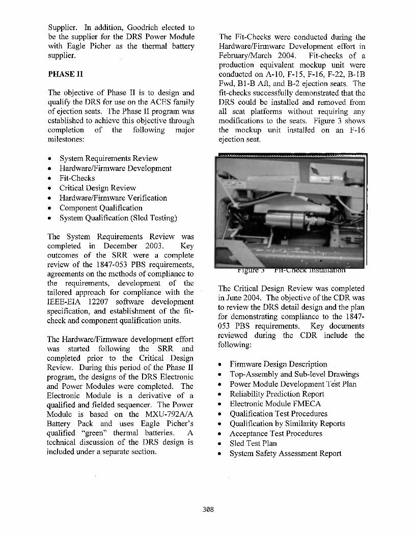
The Fit-Checks were conducted during the Hardware/Firmware Development effort in February/March 2004. Fit-checks of a production equivalent mockup unit were conducted on A- 10, F- 15, F- 16, F-22, B- 1B Fwd, B 1-B Aft, and B-2 ejection seats. The fit-checks successfully demonstrated that the DRS could be installed and removed from all seat platforms without requiring any modifications to the seats. Figure 3 shows the mockup unit installed on an F-16 ejection seat.
Figure 3 Fit-Check Installation
The Critical Design Review was completed in June 2004. The objective of the CDR was to review the DRS detail design and the plan for demonstrating compliance to the 1847- 053 PBS requirements. Key documents reviewed during the CDR include the following:
• Firmware Design Description • Top-Assembly and Sub-level Drawings • POwer Module Development Te~st Plan • Reliability Prediction Report • Electronic Module FMECA • Qualification Test Procedures • Qualification by Similarity Reports • Acceptance Test Procedures • Sled Test Plan • System Safety Assessment Report
Page 4
The Electronic and Power Module designs and methods of compliance to the 1847-053 PBS requirements were accepted by the USAF/JPO pending completion of the CDR action items. The USAF/JPO approved entry into the Hardware/Firmware Verification and Component Qualification portions of Phase II as well.
The Hardware/Firmware Verification effort was started following the CDR and testing was completed in July 2004. All firmware verification tests were conducted in accordance to the Firmware Test Plan contained in the 10002127 Firmware Design Description. The test results are under review and the preliminary analysis showed that the firmware meets the requirements of the 10002126 Firmware Requirements Document.
g
; i!ii :
Phase II is currently running on schedule with completion of the Component Qualification effort for the Electronic and Power Modules anticipated by October 2004. Sled Testing is planned to start in November 2004 with the "0/0" sled test followed by completion of the remaining three tests by March 2005.
.... .~..
. : . . ~ , ~ , : ~ . ~ . , < s .........
i i~}
!i~ii)# iiiiiiii)!iiiiiiiii!iiiiiNNiiiiiiiilNiiiiiii!~'Y . . . . ~ ~
• ~iiiiii~; ~ ~ii.';s ..... ..... i. . . . . .
i
DRS DESIGN DESCRIPTION
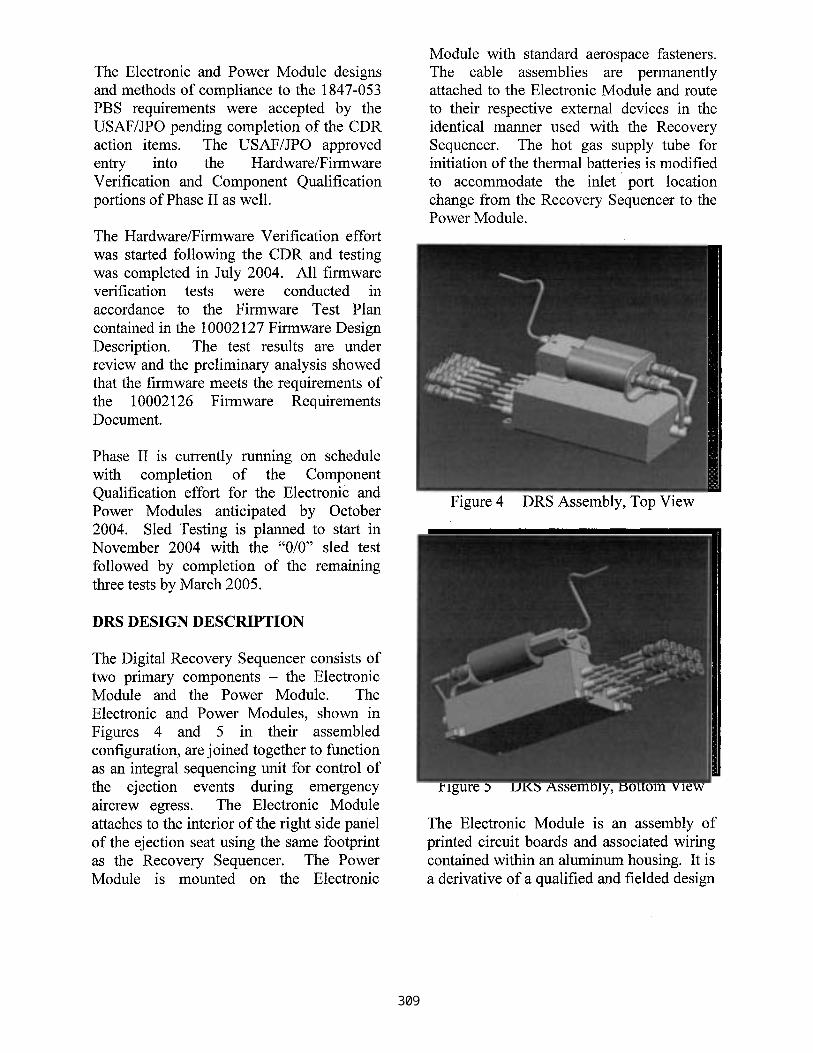
The Digital Recovery Sequencer consists of two primary components- the Electronic Module and the Power Module. The Electronic and Power Modules, shown in Figures 4 and 5 in their assembled configuration, are joined together to function as an integral sequencing unit for control of the ejection events during emergency aircrew egress. The Electronic Module attaches to the interior of the right side panel of the ejection seat using the same footprint as the Recovery Sequencer. The Power Module is mounted on the Electronic
Module with standard aerospace fasteners. The cable assemblies are permanently attached to the Electronic Module and route to their respective external devices in the identical manner used with the Recovery Sequencer. The hot gas supply tube for initiation of the thermal batteries is modified to accommodate the inlet port location change from the Recovery Sequencer to the Power Module.
Figure 4 DRS Assembly, Top View
Figure 5 DRS Assembly, Bottom View
The Electronic Module is an assembly of printed circuit boards and associated wiring contained within an aluminum housing. It is a derivative of a qualified and fielded design
Page 5
and retains the key architectural and functional features of that design. The Electronic Module uses digital technology with a unique firmware code embedded into its circuits. It has three redundant channels that use a voting scheme for mode determination, which prevents the possibility of multiple modes being simultaneously selected. The Electronic Module has two power input cables, two or three switch input cables, and six or seven EED output cables. The actual number of switch input and EED output cables is dependant on the application. It contains a Survivable Data Recorder feature to record data throughout the ejection for post- ejection analyses. It has an external test connector to retrieve the recorded ejection data and for connection to the acceptance test set. The Electronic Module incorporates the input and output cables as an integral part of its assembly, which use a double EMI shield method of construction with potted strain reliefs at the connector and adaptor ends for durability.
The Electronic Module operates by receiving electrical power from the Power Module. Following power initiation, the Electronic Module microcontrollers boot up and synchronize with each other. The Electronic Module receives the start switch and environmental switch inputs and based on the switch settings, determines the appropriate ejection mode. Once the ejection mode is determined, the Electronic Module controls its outputs to the applicable EED's based on its firmware/hardware circuits in accordance to the specified event timings in the 1847-053 PBS. The Survivable Data Recorder feature records the input switch positions, the selected mode, and actual event sequence timing.
The Power Module is an assembly of two redundant thermal batteries, a manifold
assembly, and a mounting clip. It is based on the MXU-792A/A Battery Pack and uses the same "green" thermal batteries. The manifold assembly consists of dual firing pins contained within firing bodies screwed into the manifold body. The firing pins are held in place in the firing bodies with shear pins. The manifold body has dual ports and an internal cross channel between the ports. One port contains a standard union fitting and the other is plugged.
The Power Module operates by receiving ballistic hot gas from the CKU-5 rocket catapult. The hot gas travels from the CKU- 5 through a tube assembly into the standard union fitting. The hot gas then flows into the firing bodies and through the cross- channel, causing the firing pins to strike the thermal battery primers. The shear pins used to retain the firing pins in place are designed to withstand 400 psig and completely shear between 400 and 650 psig.
Use of a separate Electronic Module and removable Power Module was implemented to overcome the life-limited aspects of the Recovery Sequencer. The thermal batteries with an installed life of 7.5 years are the primary life-limiting component on both the DRS and the Recovery Sequencer. By being able to replace the thermal batteries independent of the electronics, the Electronic Module can remain installed for over 20 years without removal, The component obsolescence and mode differentiation issues of the Recovery Sequencer are eliminated by using digital based electrical components with~ a triple redundant voting architecture. Use of firmware written in a higher order language, provisions for an extra EED interface, and capacity for expansion of the electronics within the Electronic Module housing provide the needed flexibility in the DRS for incorporation of future product
Page 6
improvements. The Survivable Data Recorder was added to capture data during actual ejections that will be used to develop a better understanding of the performance of the seat. The external test connector supports the future incorporation of a field test set. The cable assemblies are permanently attached to Electronic Module for reliability and cost purposes. They replace the method of construction used by the Recovery Sequencer cable assemblies with an alternate proven method of construction that alleviates durability issues and still interface with their respective devices without seat modifications. The DRS retains the Environmental Sensor airspeed and altitude inputs for selection of the mode of operation, and activation of the thermal batteries with hot gas from the CKU-5 rocket catapult to minimize impacts to the system seat design.
The DRS as it is currently defined provides a significant advancement in aircrew safety by eliminating the limitations of the Recovery Sequencer. It also provides the foundation for incorporation of future safety improvements through its ability to grow without significant hardware changes and record actual ejection event data
CONCLUSION
The Digital Recovery Sequencer program was initiated to design and qualify a replacement to the Recovery Sequencer used on the ACES family of ejection seats. Replacement of the Recovery Sequencer is highly desirable due to design limitations including a short installed life, electronic component obsolescence, limited growth capacity, and the potential to simultaneously select two modes of operation. The DRS configuration overcomes the life limitation of the Recovery Sequencer by enabling replacement of the life-limited thermal
batteries independent of the electronics. It eliminates the obsolescence and the potential for simultaneous selection of two modes, and creates design flexibility by using a firmware based design approach with digital components. It includes the capacity to physically expand with minimal hardware changes and a Survivable Data Recorder to capture live ejection data for use in incorporating future product improvements.
The DRS program was established with three phases. Phase I is complete and Phase II is underway. Phase III is not scheduled to-date. Phase II started in November 2003 and is complete through the Critical Design Review. The component qualification effort is scheduled to start in September 2004 with Sled Testing to follow starting in November 2004. Key accomplishments completed during Phase II thus far include:
1. Establishment of the DRS requirements and compliance methods during the SRR
2. Completion of the designs of the Electronic and Power Modules during Hardware/Firmware Development
3. Successful demonstration of the installation and removal of the DRS mockup unit during the Fit-Checks
4. Acceptance of the Electronic and Power Module designs and approval for entry into the Component Qualification effort
Overall, the Digital Recovery Sequencer provides a significant advancement in aircrew safety, forms the foundation for incorporation of future safety improvements, and is on target for being qualified by June 2005.
Page 7
REFERENCES
"JESP ACES II Description," Goodrich- PAZ, 29 January 2001,
1847-053 "Specification-Digital Recovery Sequencer;" Revision E
10002127 "DRS Firmware Design Description." Revision N/C
BIOGRAPHIES
Mr. David A. "Andy" Ross is a project engineer for the ACES II Program at Goodrich with more than 3 years experience in the escape system industry. Andy is the lead engineer for the Digital Recovery Sequencer (DRS) Phase II design, development, and qualification program. Andy was a project engineer at The Boeing Company on commercial aircraft platforms for over 10 years prior to his Goodrich employment. Andy graduated from Arizona State University with a BS in Aerospace Engineering in 1988.
Mr. David Culhane is the Electronics Engineer for the CAD/PAD Joint Program Office (JPO). David has been with the Indian Head Division, Naval Surface Warfare Center for over 13 years, and has provided engineering support to the Digital Recovery Sequencer Program for the past 36 months. David graduated from the Marine Corps Communications and Electronics School in 1987, and received a BS in Electrical Engineering from Capitol College in 1996.
MSgt Steven Ferrell is the System Program Office military liaison for Aircrew Protection systems sustainment and improvement program(s)at Brooks City Base. MSgt Ferrell has over 19 years of experience maintaining escape systems with
extensive knowledge of ACES II seat design and function. He is actively involved in ACES II Cooperative Modification Upgrades of all ACES seats and has been chosen to provide subject matter expertise to the Digital Recovery Sequencer program. He provides advanced performance, survival, force protection and aircraft mishap analysis capabilities to U.S. air, ground and naval forces through development, production, acquisition and sustainment of human centered systems including life support, egress and survival equipment. He holds two Associates of Science Degrees from the Community College of the Air Force.
Mr. Lee Cotter is a Program Manager at Teledyne Electronic Safety Products. He is also responsible for New Business and Product Development. He has 20 years in the escape system industry most of which was served as the Engineering Manager at
• TESP during the development of nearly all of their escape related and other products. Prior to that he had 16 years of engineering and management experience in the inertial instruments, flight control and navigation world. He has a B.S. in Mathematical Physics from Cal. State Northridge.
8

![Sequencer 1, Sequencer 2 or Drum - medias.arturia.net · —Sequencer 1, Sequencer 2 or Drum SHIFT + [>>] = Extend sequence SHIFT + Knob 1 = Offset value for all active steps](https://img.pdfslide.net/doc/110x75/5b87086c7f8b9aa0218be152/sequencer-1-sequencer-2-or-drum-sequencer-1-sequencer-2-or-drum-shift.jpg)


![Sequencer 1, Sequencer 2 or Drum - Arturiadownloads.arturia.com/products/beatstep-pro/manual/BeatStepPro... · —Sequencer 1, Sequencer 2 or Drum SHIFT + [>>] = Extend sequence SHIFT](https://img.pdfslide.net/doc/110x75/5adbc3047f8b9add658e5b6e/sequencer-1-sequencer-2-or-drum-sequencer-1-sequencer-2-or-drum-shift-.jpg)