Embed Size (px)
Citation preview
7/26/2019 Digital Relays Wiki
http://slidepdf.com/reader/full/digital-relays-wiki 1/4
Digital protective relay
From Wikipedia, the free encyclopedia
This article needs additional citations for verification. Please help improve this article by adding
citations to reliable sources. Unsourced material may be challenged and removed. (September 2014)
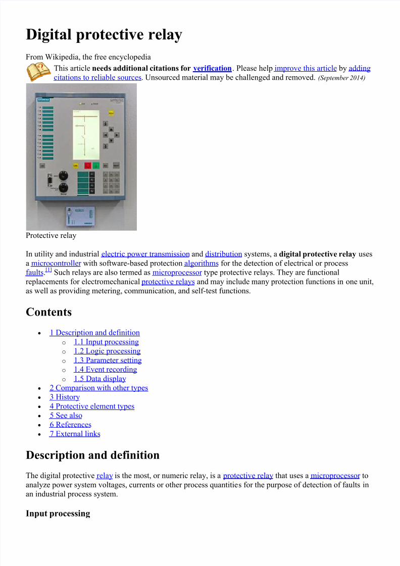
Protective relay
In utility and industrial electric power transmission and distribution systems, a digital protective relay uses
a microcontroller with software-based protection algorithms for the detection of electrical or process
faults.[1] Such relays are also termed as microprocessor type protective relays. They are functional
replacements for electromechanical protective relays and may include many protection functions in one unit,
as well as providing metering, communication, and self-test functions.
Contents
1 Description and definition
o 1.1 Input processing
o
1.2 Logic processing
o 1.3 Parameter setting
o
1.4 Event recording
o
1.5 Data display
2 Comparison with other types
3 History 4 Protective element types
5 See also
6 References
7 External links
Description and definition
The digital protective relay is the most, or numeric relay, is a protective relay that uses a microprocessor to
analyze power system voltages, currents or other process quantities for the purpose of detection of faults in
an industrial process system.
Input processing

7/26/2019 Digital Relays Wiki
http://slidepdf.com/reader/full/digital-relays-wiki 2/4
Low voltage and low current signals (i.e., at the secondary of a voltage transformers and current
transformers) are brought into a low pass filter that removes frequency content above about 1/3 of the
sampling frequency (a relay A/D converter needs to sample faster than twice per cycle of the highest
frequency that it is to monitor). The AC signal is then sampled by the relay's analog to digital converter from
4 to 64 (varies by relay) samples per power system cycle. As a minimum, magnitude of the incoming
quantity, commonly using Fourier transform concepts (RMS and some form of averaging) would be used in
a simple relay function. More advanced analysis can be used to determine phase angles, power , reactive
power , impedance, waveform distortion, and other complex quantities.
Only the fundamental component is needed for most protection algorithms, unless a high speed algorithm is
used that uses subcycle data to monitor for fast changing issues. The sampled data is then passed through a
low pass filter that numerically removes the frequency content that is above the fundamental frequency of
interest (i.e., nominal system frequency), and uses Fourier transform algorithms to extract the fundamental
frequency magnitude and angle.
Logic processing
The relay analyzes the resultant A/D converter outputs to determine if action is required under its protection
algorithm(s). Protection algorithms are a set of logic equations in part designed by the protection engineer,and in part designed by the relay manufacturer. The relay is capable of applying advanced logic. It is capable
of analyzing whether the relay should trip or restrain from tripping based on parameters set by the user,
compared against many functions of its analogue inputs, relay contact inputs, timing and order of event
sequences.
If a fault condition is detected, output contacts operate to trip the associated circuit breaker(s).
Parameter setting
The logic is user-configurable and can vary from simply changing front panel switches or moving of circuit
board jumpers to accessing the relay's internal parameter setting webpage via communications link onanother computer hundreds of kilometres away.
The relay may have an extensive collection of settings, beyond what can be entered via front panel knobs
and dials, and these settings are transferred to the relay via an interface with a PC ( personal computer ), and
this same PC interface may be used to collect event reports from the relay.
Event recording
In some relays, a short history of the entire sampled data is kept for oscillographic records. The event
recording would include some means for the user to see the timing of key logic decisions, relay I/O
(input/output) changes, and see, in an oscillographic fashion, at least the fundamental component of the
incoming analogue parameters.
Data display
Digital/numerical relays provide a front panel display, or display on a terminal through a communication
interface. This is used to display relay settings and real-time current/voltage values, etc.
More complex digital relays will have metering and communication protocol ports, allowing the relay to
become an element in a SCADA system. Communication ports may include RS232/RS485 or Ethernet
(copper or fibre-optic). Communication languages may include Modbus, DNP3 or IEC61850 protocols.
Comparison with other types

7/26/2019 Digital Relays Wiki
http://slidepdf.com/reader/full/digital-relays-wiki 3/4
Electromechanical protective relays at a hydroelectric generation station
By contrast, an electromechanical protective relay converts the voltages and currents to magnetic and
electric forces and torques that press against spring tensions in the relay. The tension of the spring and taps
on the electromagnetic coils in the relay are the main processes by which a user sets such a relay.
In a solid state relay, the incoming voltage and current waveforms are monitored by analog circuits, not
recorded or digitized. The analog values are compared to settings made by the user via potentiometers in the
relay, and in some case, taps on transformers.
In some solid state relays, a simple microprocessor does some of the relay logic, but the logic is fixed and
simple. For instance, in some time overcurrent solid state relays, the incoming AC current is first converted
into a small signal AC value, then the AC is fed into a rectifier and filter that converts the AC to a DC value
proportionate to the AC waveform. An op-amp and comparator is used to create a DC that rises when a trip
point is reached. Then a relatively simple microprocessor does a slow speed A/D conversion of the DC
signal, integrates the results to create the time-overcurrent curve response, and trips when the integration
rises above a setpoint. Though this relay has a microprocessor, it lacks the attributes of a digital/numeric
relay, and hence the term "microprocessor relay" is not a clear term.
History
The digital/numeric relay was introduced in the early 1980s, with AREVA, ABB Group's forerunners and
SEL making some of the early market advances in the arena, but the arena has become crowded today with
many manufacturers. In transmission line and generator protection, by the mid-1990s the digital relay had
nearly replaced the solid state and electromechanical relay in new construction. In distribution applications,
the replacement by the digital relay proceeded a bit more slowly. While the great majority of feeder relays in
new applications today are digital, the solid state relay still sees some use where simplicity of the application
allows for simpler relays, which allows one to avoid the complexity of digital relays.
Protective element types
Protective elements refer to the overall logic surrounding the electrical condition that is being monitored.
For instance, a differential element refers to the logic required to monitor two (or more) currents, find their
difference, and trip if the difference is beyond certain parameters. The term element and function are quite
interchangeable in many instances.
For simplicity on one-line diagrams, the protection function is usually identified by an ANSI device number.
In the era of electromechanical and solid state relays, any one relay could implement only one or two
protective functions, so a complete protection system may have many relays on its panel. In a
digital/numeric relay, many functions are implemented by the microprocessor programming. Any one
numeric relay may implement one or all of these functions.
A listing of device numbers is found at ANSI Device Numbers. A summary of some common device
numbers seen in digital relays is:
7/26/2019 Digital Relays Wiki
http://slidepdf.com/reader/full/digital-relays-wiki 4/4
11 - Multifunction Device
21 - Impedance
24 - Volts/Hz
25 - Synchronizing
27 - Under Voltage
32 - Directional Power Element
46 - Negative Sequence Current
40 - Loss of Excitation
47 - Negative Sequence Voltage
50 - Instantaneous Overcurrent (N for neutral, G for ground current)
51 - Inverse Time Overcurrent (N for neutral, G from ground current)
59 - Over Voltage
62 - Timer
64 - Ground Fault (64F = Field Ground, 64G = Generator Ground)
67 - Directional Over Current (typically controls a 50/51 element)
79 - Reclosing Relay
81 - Under/Over Frequency
86 - Lockout Relay / Trip Circuit Supervision
87 - Current Differential (87L=transmission line diff; 87T=transformer diff; 87G=generator diff)
See also
Polyphase system
Overhead powerline
Power outage
Three-phase electric power
References
1. "Schweitzer Programmable Automation Controller". Schweitzer Engineering Laboratories. Retrieved
21 November 2012.
External links
List of manufacturers of protective relays
Categories:
Electric power infrastructure Electric power distribution
Electrical engineering