Embed Size (px)
Citation preview
8/4/2019 Digital Respiration Rate Meter
http://slidepdf.com/reader/full/digital-respiration-rate-meter 1/5
Digital respiration rate meter
DIGITAL RESPIRATION RATE METER
Introduction Measurement of physiological parameters like heart rate and respiration
rate is crucial in the field of medicine. Here is a simple method for respiration rate
measurement using a displacement transducer. Its responds fast and is cost
effective. By using this, respiration rate can be measured in the range of 0 to 999respirations/ minute.
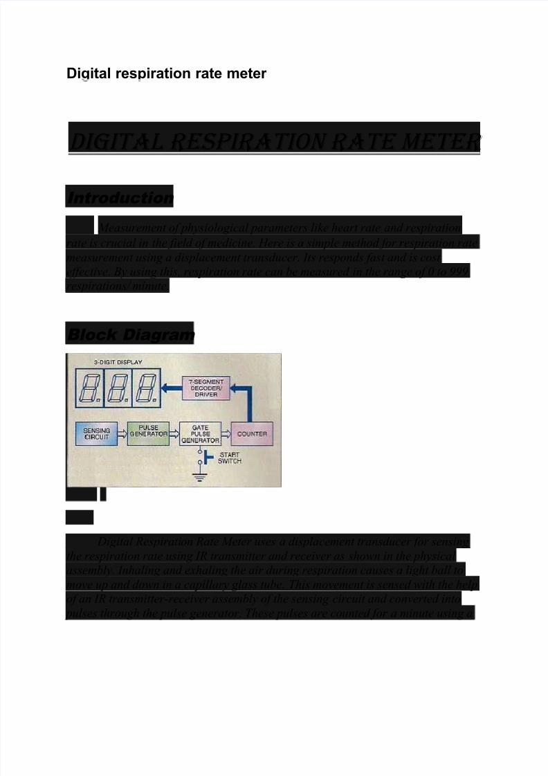
Bl ock Diagram
Digital Respiration Rate Meter uses a displacement transducer for sensing the respiration rate using IR transmitter and receiver as shown in the physical
assembly. Inhaling and exhaling the air during respiration causes a light ball to
move up and down in a capillary glass tube. This movement is sensed with the help
of an IR transmitter-receiver assembly of the sensing circuit and converted into
pulses through the pulse generator. These pulses are counted for a minute using a
8/4/2019 Digital Respiration Rate Meter
http://slidepdf.com/reader/full/digital-respiration-rate-meter 2/5
counter. The respiration rate is displayed on a 3-digit display through the seven segment decoder/driver.
Start switch S1 is used to reset the display to zero and enable the counter
for a minute to count the respiration pulse. The gate pulse generator consists of a
monostable multivibrator. When triggered by start switch, it generates gating pulseof one minute duration.
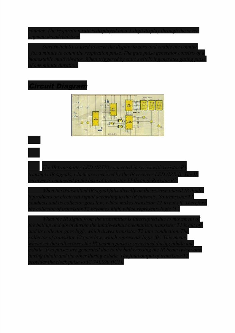
C ircuit Diagram
The IR transmitter LED (IRTX) connected in series with resistor R1
transmits IR signals, which are received by the IR receiver LED (IRRX). The IRreceiver is connected to the base of transistor T1 through Resistor R2.
When the transmitted IR signal falls directly on the reverse biased IR diode,
it produces an electrical signal according to the IR intensity. So transistor T1
conducts and its collector goes low, which makes transistor T2 to cut off. Thereforethe collector of transistor T2 becomes high, which represents logic µ1¶.
When the IR signal from the transmitter is interrupted due to movement of
the ball up and down during the inhale-exhale mechanism, transistor T1 is cut off
and its collector goes high, which drives transistor T2 into conduction. Thecollector of transistor T2 goes low, which represents logic µ0¶. This means
whenever the ball crosses the IR beam a pulse is generated during inhale and
exhale. Two pulses are generated due to the ball crossing the IR beam twice: one
during inhale and the other during exhale. The final output of transistor T2
provides the clock pulse to IC 74LS90 (IC1).

8/4/2019 Digital Respiration Rate Meter
http://slidepdf.com/reader/full/digital-respiration-rate-meter 3/5
IC 74LS90 is configured as a divide-by-two counter and its output is used as
the clock pulse for three-digit BCD counter CD4553 (IC4). The output of counter
IC1 is connected to input pin 8 of NAND gate N1 of IC3. Input pin 9 of NAND gate
N1 is connected to output pin 3 of monostable multivibrator IC2. The time period
of the monostable is decided by resistor R6, preset VR1 is used to adjust the time period of the monostable to 1 minute.
When start switch S1 is pressed, pin 2 of the monostable goes low and it
triggers to generate a pulse of one minute duration, which is fed to pin 9 of NAND
gate N1. Therefore the gate is open for one minute to pass the clock pulses coming
from IC1 to pin 12 of the three digit counter CD4553. This one minute pulse of the
monostable is inverted by NAND gate N2, which controls the latch enable (LE) of
CD4553. When the monostable output goes high, the latch enable (LE) of CD4553
goes low and the counter advances. When the monostable output goes low thelatch enable (LE) of IC4 goes high and the counting stops. So there is no further change in the count shown on the 7-segment display.
When start switch S1 is pressed pin 13 of CD4553 and the 7-segment display
shows µ000¶. The CD4553 consists of three negative edge triggered BCD counters
that are cascaded synchronously. A quad latch at the output of each counter
permits storage of any given count. The information is then time-division-
multiplexed, providing one BCD number or digit at a time. Digit-Select outputs
provide display control. All the outputs are TTL-compatible. An on-chip oscillator
provides low frequency scanning clock pulse, which drives the multiplexer output selector.
The BCD count outputs of CD4553 are fed to inputs µA¶ through µD¶ of 7-
segment decoder and driver CD4511 (IC5). CD4511 shows the count on 7-segment
displays DIS1 through DIS3. Resistors R10 through R16 are used for limiting thecurrent.
CD4553 provides BCD counts on D0 through D3 and display-enable signal
from DIS1 through DIS3 pins simultaneously in time-division-multiplexed mode for
displaying a particular number on the 7-segment display unit. Segment data and display-enable pulse for display are refreshed more than 25 times every second.
Thus, the display appears to be continuous, even through DIS1 through DIS3 light up one by one.
When pin 2 of CD4553 goes low to drive transistor T5 into saturation and
provides ground path to common-cathode pin 3 or pin 8 of DIS1, pin 1 and 15 of
8/4/2019 Digital Respiration Rate Meter
http://slidepdf.com/reader/full/digital-respiration-rate-meter 4/5
CD4553 also go low and transistor T4 and T3 drive common-cathode pin 3 or 8 of displays DIS2 and DIS3.
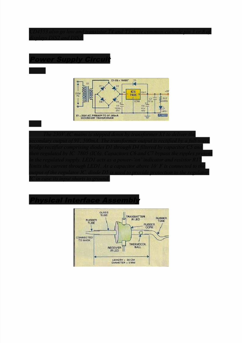
P ower Supp ly C ircuit
The 230V AC mains is stepped down by transformer X1 to deliver the
secondary output of 9V, 500mA. The transformer output is rectified by a full-wave
bridge rectifier comprising diodes D1 through D4 filtered by capacitor C5 and
then regulated by IC 7805 (IC6). Capacitors C6 and C7 bypass the ripples present
in the regulated supply. LED1 acts as a power-µon¶ indicator and resistor R17
limits the current through LED1. As a capacitor above 10µ F is connected to the
output of the regulator IC, diode D5 is used to provide protection to the regulator
IC in case its input shorts to ground.
Ph ys ica l Interface Ass emb ly

8/4/2019 Digital Respiration Rate Meter
http://slidepdf.com/reader/full/digital-respiration-rate-meter 5/5
The interface assembly simply make use of a nose mask, which is readily
available in medical shops and mainly used in hospitals for supply of oxygen to the patients for respiration