Embed Size (px)
Citation preview
Index Page
English 1Español 7Français 13Deutsch 19Italiano 25
D I G I T A L S O L D E R I N G S T A T I O N S
LD 3100ID 3110TD 3120SD 3140
1
We appreciate the confidence you have shown in JBC by purchasing this station.It has been manufactured with the highest standards of quality to ensure reliableservice. Before starting up the apparatus, we suggest you to read through thefollowing instructions carefully.
ENGLISH
FEATURES
Stations compositionMD 3050 230V Ref. 3050200:
- Control Unit Ref. 3430200- 5W soldering iron
with tip R-0 D Ref. 3030000- Soldering iron stand MS 1300 Ref. 0290130- Instructions manual Ref. 0415470
LD 3100 230V Ref. 3100200:
- Control Unit Ref. 3130200- 20W soldering iron
with tip B-05 D Ref. 3000000- Soldering iron stand LS 1100 Ref. 0290110- Instructions manual Ref. 0415470
ID 3110 230V Ref. 3110200:
- Control Unit Ref. 3130200- 50W soldering iron
with tip R-10 D Ref. 3010000- Soldering iron stand US 1000 Ref. 0290100- Instructions manual Ref. 0415470
TD 3120 230V Ref. 3120200:
- Control Unit Ref. 3130200- 60W soldering iron with solder
feed system and tip C-20 D Ref. 3020000- Soldering iron stand TS 1200 Ref. 0290120- Instructions manual Ref. 0415470
SD 3140 230V Ref. 3140200:- Control Unit Ref. 3730200- 70W soldering iron
with tip T-55 D Ref. 3070000- Soldering iron stand US 1000 Ref. 0290100- Instructions manual Ref. 0415470
The 20, 50, 60 and 70W soldering irons may beconnected to Control Unit Ref. 3130200 thoughit is recommended to use the 70W solderingiron with Control Unit Ref. 3730200, which isspecially suited to the power needs of thatsoldering iron. This latter control unit can alsobe used with all the soldering irons except the5W one, which needs its own Control Unit Ref.3430200.
2
ENGLISH
Control Unit techical data1. Safety transformer with mains separator:
LD-ID-TD-SD: 230V/24V 50Hz.MD: 230V/12V 50Hz.
2. Temperature range: 50°C to 400°C inone-degree intervals.
3. Programmed temperature accurate to ±3%.
4. Microprocesor with five user-programmablefunctions.
5. Keeps all programmed data in store, evenwhen the appliance is switched off.
6. Digital lecture by LCD display.
7. Abides the CE standards for electricalsecurity, electromagnetical compatibil ityand antistatic protection.
8. Equipotential connector is earth connected tothe plug feed of the station.
OPERATION
Use of keys
< = Reduces values.N (No) = Invalidates programming.T1 = Selection of temperature 1
> = Increases values..Y (Yes) = Validates programming
and changes LOOP.T2 = Selection of temperature 2
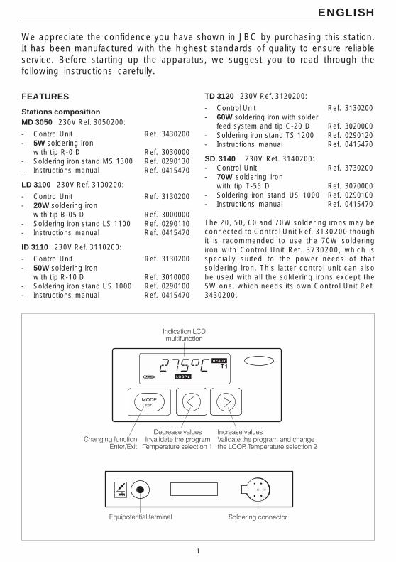
Switches from one function toanother and programme enter/exit.
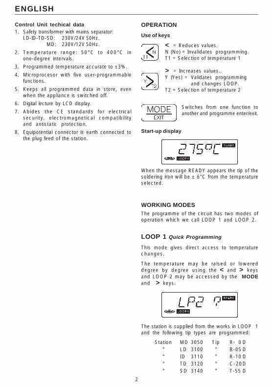
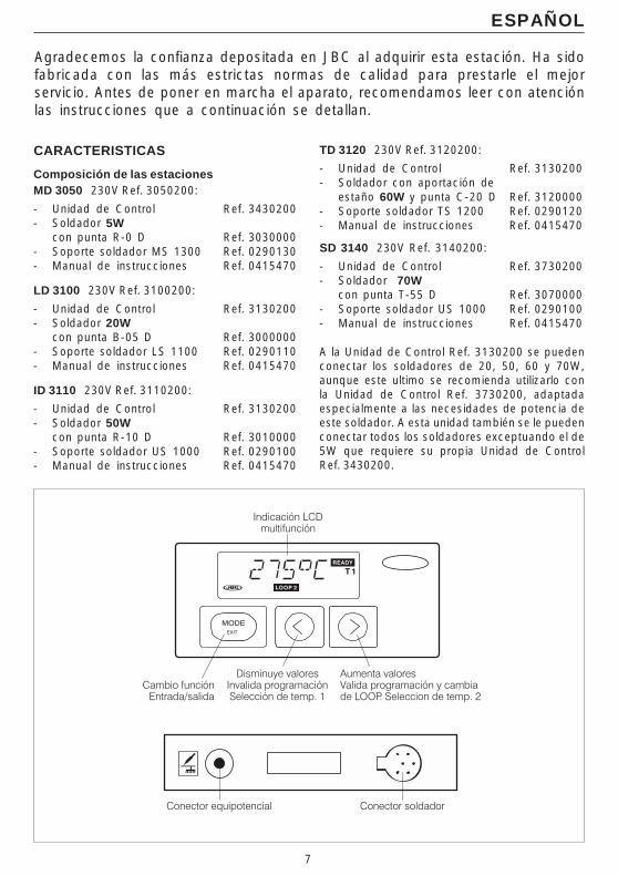
Start-up display
When the message READY appears the tip of thesoldering iron will be ± 6°C from the temperatureselected.
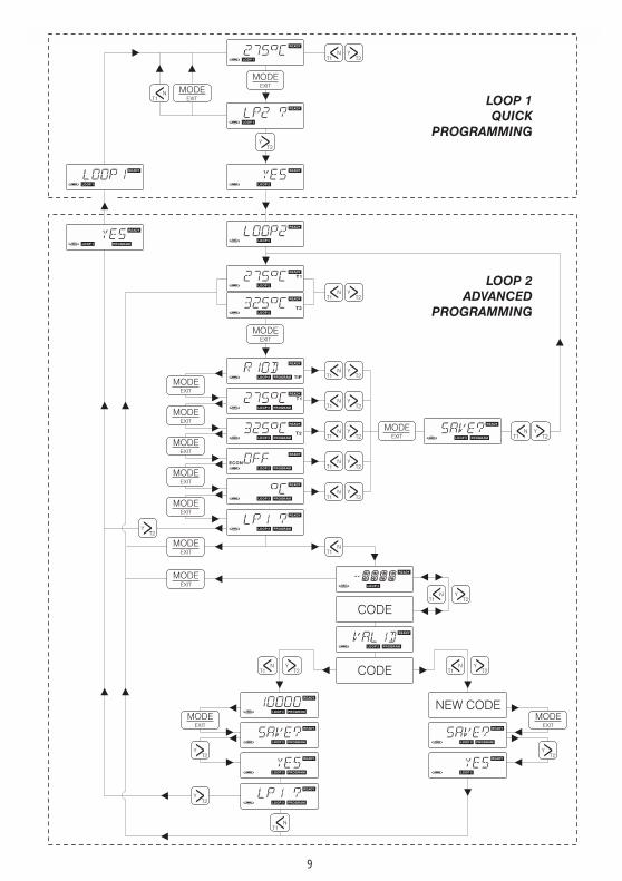
WORKING MODESThe programme of the circuit has two modes ofoperation which we call LOOP 1 and LOOP 2.
LOOP 1 Quick Programming
This mode gives direct access to temperaturechanges.
The temperature may be raised or lowereddegree by degree using the < and > keysand LOOP 2 may be accessed by the MODEand > keys.
The station is supplied from the works in LOOP 1and the following tip types are programmed:
Station MD 3050 Tip R- 0 D" LD 3100 " B-05 D" ID 3110 " R-10 D" TD 3120 " C-20D" SD 3140 " T-55 D

3
4
ENGLISH
To change the tip model or the °C-°F unit thedata must be programmed in LOOP 2 andthese changes will be taken up in LOOP 1.
LOOP 2 Advanced Programming
Advanced programming system, allowing accessto the 5 functions provided by the system.
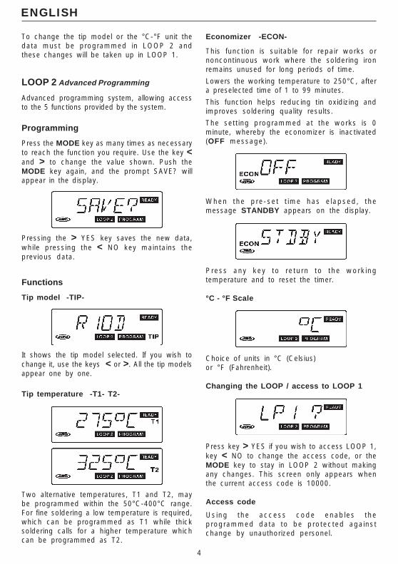
Programming
Press the MODE key as many times as necessaryto reach the function you require. Use the key <and > to change the value shown. Push theMODE key again, and the prompt SAVE? willappear in the display.
Pressing the > YES key saves the new data,while pressing the < NO key maintains theprevious data.
Functions
Tip model -TIP-
It shows the tip model selected. If you wish tochange it, use the keys < or >. All the tip modelsappear one by one.
Tip temperature -T1- T2-
Two alternative temperatures, T1 and T2, maybe programmed within the 50°C-400°C range.For fine soldering a low temperature is required,which can be programmed as T1 while thicksoldering calls for a higher temperature whichcan be programmed as T2.
Economizer -ECON-
This function is suitable for repair works ornoncontinuous work where the soldering ironremains unused for long periods of time.
Lowers the working temperature to 250°C, aftera preselected time of 1 to 99 minutes.
This function helps reducing tin oxidizing andimproves soldering quality results.
The setting programmed at the works is 0minute, whereby the economizer is inactivated(OFF message).
When the pre-set t ime has e lapsed, themessage STANDBY appears on the display.
Press any key to return to the workingtemperature and to reset the timer.
°C - °F Scale
Choice of units in °C (Celsius)or °F (Fahrenheit).
Changing the LOOP / access to LOOP 1
Press key > YES if you wish to access LOOP 1,key < NO to change the access code, or theMODE key to stay in LOOP 2 without makingany changes. This screen only appears whenthe current access code is 10000.
Access code
Using the access code enables theprogrammed data to be protected againstchange by unauthorized personel.
5
ENGLISH
There are two access code categories:
- NO PROTECTION
The code is 10000. It allows to modify alldata and move from one Loop to another.This code is assigned at source.
- COMPLETE PROTECTION
Numbers be tween 00001 and 99999(except 10000) . In th is category i t isessential to enter the access code beforeany data can be modified. Does not allowaccess to LOOP 1.
Entering the access code
If you are accessing this display for the first time,you will first of all have to enter the factory-programmed one, i.e. 10000.
1 )To enter the figure 1 press < twice.
2 )Press > to move the first digit to the right.
3 )To enter the first 0 press the < key once, andso on with the others. Press > to end.
The VALID message which comes up on thedisplay indicates that the number has beenentered correctly.Then, the new password may be enteredfollowing the same process.
If an attempt has been made to enter thepassword and the number is wrong, it will winkon the display. To enter the correct password,push MODE until the enter display appears.
RECOMMENDATIONS FOR USE
For soldering- The components and the circuit should be
cleaned and degreased.
- Preferably select a temperature below 375°C.Excess temperature may cause the printedcircuit tracks to break loose.
- The tip must be well tinned for good heatconduction. If it has been inoperative for anylength of time, it should be retinned.
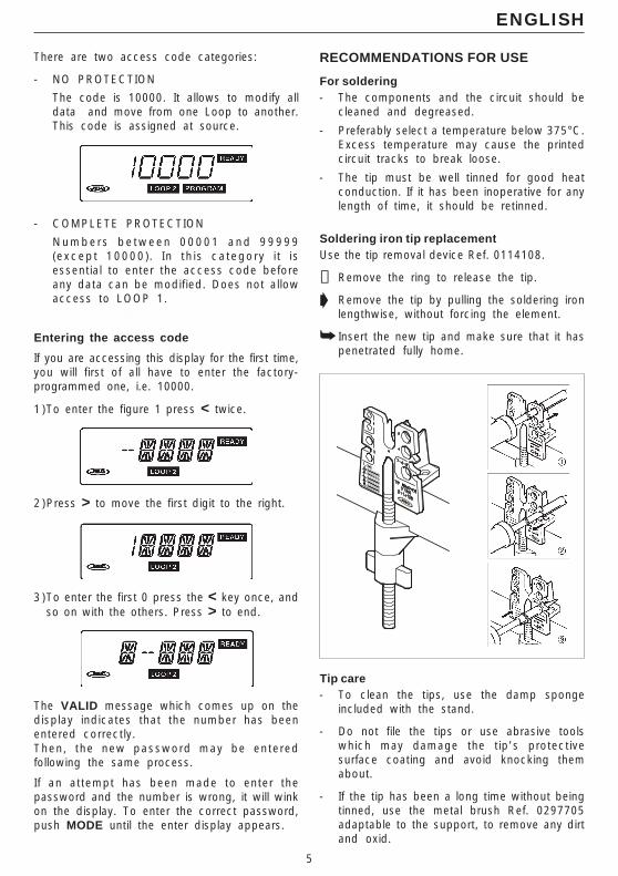
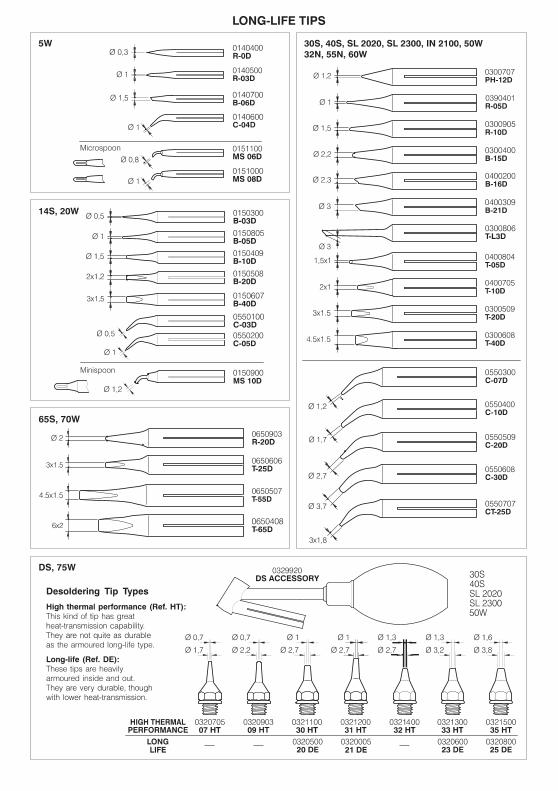
Soldering iron tip replacementUse the tip removal device Ref. 0114108.
➋ Remove the ring to release the tip.
➧ Remove the tip by pulling the soldering ironlengthwise, without forcing the element.
➥ Insert the new tip and make sure that it haspenetrated fully home.
Tip care- To clean the tips, use the damp sponge
included with the stand.
- Do not file the tips or use abrasive toolswhich may damage the tip’s protectivesurface coating and avoid knocking themabout.
- If the tip has been a long time without beingtinned, use the metal brush Ref. 0297705adaptable to the support, to remove any dirtand oxid.
6
TECHNICAL SERVICETroubleshooting and solutions
Whenever an ERR message appears, the controlunit switches off completely. To reconnect, usethe main start switch. The following messages willappear on the display:
- BLANK DISPLAYElectricity supply failure. Check that theapparatus is turned on or whether the fuse atthe back of the box (T 315 mA) has blown.
- ERR 1The temperature does not rise. Possiblecauses: heating element fused, heating elementsupply cable cut, faulty triac. Check andreplace as required.
- ERR 2The temperature rises uncontrollably. Possiblecauses: crossed Triac.
- ERR 3There is no thermocouple reading. Possiblecauses: the soldering iron is not connected tothe unit, thermocouple open, soldering ironcord broken.
- ERR 4Irregular thermocouple readings. Possiblecauses: thermocouple or its connections inbad condition.
- ERR 5The permanent memory is not functioning.Information cannot be saved or read. Replacethe whole circuit.
ENGLISH
OFFCALRSTPW
Bridge
JBC reserves the right to change specifications mentioned inthis instructions manual without prior notice.
Cancelling the access code
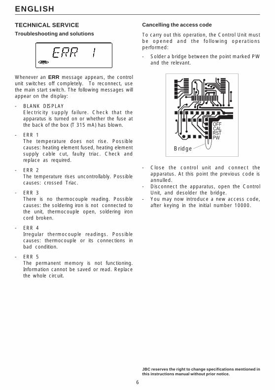
To carry out this operation, the Control Unit mustbe opened and the fo l lowing operat ionsperformed:
- Solder a bridge between the point marked PWand the relevant.
- Close the control unit and connect theapparatus. At this point the previous code isannulled.
- Disconnect the apparatus, open the ControlUnit, and desolder the bridge.
- You may now introduce a new access code,after keying in the initial number 10000.
7
Agradecemos la confianza depositada en JBC al adquirir esta estación. Ha sidofabricada con las más estrictas normas de calidad para prestarle el mejorservicio. Antes de poner en marcha el aparato, recomendamos leer con atenciónlas instrucciones que a continuación se detallan.
ESPAÑOL
CARACTERISTICAS
Composición de las estacionesMD 3050 230V Ref. 3050200:
- Unidad de Control Ref. 3430200- Soldador 5W
con punta R-0 D Ref. 3030000- Soporte soldador MS 1300 Ref. 0290130- Manual de instrucciones Ref. 0415470
LD 3100 230V Ref. 3100200:
- Unidad de Control Ref. 3130200- Soldador 20W
con punta B-05 D Ref. 3000000- Soporte soldador LS 1100 Ref. 0290110- Manual de instrucciones Ref. 0415470
ID 3110 230V Ref. 3110200:
- Unidad de Control Ref. 3130200- Soldador 50W
con punta R-10 D Ref. 3010000- Soporte soldador US 1000 Ref. 0290100- Manual de instrucciones Ref. 0415470
TD 3120 230V Ref. 3120200:
- Unidad de Control Ref. 3130200- Soldador con aportación de
estaño 60W y punta C-20 D Ref. 3120000- Soporte soldador TS 1200 Ref. 0290120- Manual de instrucciones Ref. 0415470
SD 3140 230V Ref. 3140200:
- Unidad de Control Ref. 3730200- Soldador 70W
con punta T-55 D Ref. 3070000- Soporte soldador US 1000 Ref. 0290100- Manual de instrucciones Ref. 0415470
A la Unidad de Control Ref. 3130200 se puedenconectar los soldadores de 20, 50, 60 y 70W,aunque este ultimo se recomienda utilizarlo conla Unidad de Control Ref. 3730200, adaptadaespecialmente a las necesidades de potencia deeste soldador. A esta unidad también se le puedenconectar todos los soldadores exceptuando el de5W que requiere su propia Unidad de ControlRef. 3430200.
8
Datos técnicos de la Unidad de Control1. Transformador de seguridad separador de red:
LD-ID-TD-SD: 230V/24V 50Hz.MD: 230V/12V 50Hz.
2. Selección de temperatura entre: 50°C y 400°Cen intervalos de un grado.
3. Precisión de la temperatura programada: ±3%.
4. Microprocesador con 5 funcionesprogramables por el usuario.
5. Conservación de todos los datosprogramados, inc luso con e l aparatodesconectado.
6. Lectura digital por display LCD.
7. Cumple la normativa CE sobre seguridadeléctrica, compatibilidad electromagnética yprotección antiestática.
8. El conector equipotencial está conectado a latoma de tierra de la clavija de la estación.
ESPAÑOL
FUNCIONAMIENTO
Utilidad de las teclas
< = Disminuye valores.N (No) = Invalida programación.T1 = Selección de temperatura 1
> = Aumenta valores.Y (Yes) = Valida programación y
cambia de LOOP.T2 = Selección de temperatura 2
Pasar de una función a otra yentrar/salir de programación.
Pantalla inicial
Cuando aparezca el mensaje READY (listo) lapunta del soldador estará a ± 6°C de latemperatura seleccionada.
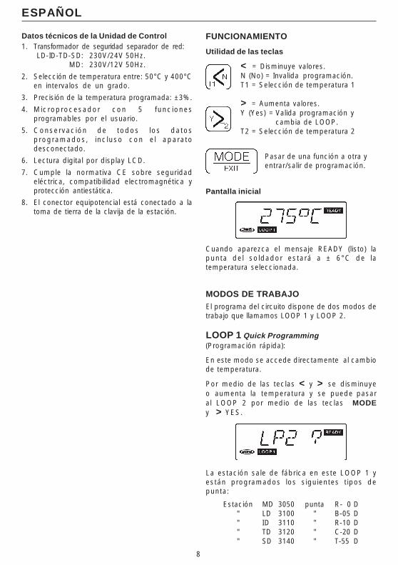
MODOS DE TRABAJOEl programa del circuito dispone de dos modos detrabajo que llamamos LOOP 1 y LOOP 2.
LOOP 1 Quick Programming(Programación rápida):
En este modo se accede directamente al cambiode temperatura.
Por medio de las teclas < y > se disminuyeo aumenta la temperatura y se puede pasaral LOOP 2 por medio de las teclas MODEy > YES.
La estación sale de fábrica en este LOOP 1 yestán programados los siguientes tipos depunta:
Estación MD 3050 punta R- 0 D" LD 3100 " B-05 D" ID 3110 " R-10 D" TD 3120 " C-20 D" SD 3140 " T-55 D
9
1 0
ESPAÑOL
Para cambiar el modelo de punta o la unidad °C-°Fse deben programar en el LOOP 2, estos cambiosquedarán asumidos en el LOOP 1.
LOOP 2 Advanced Programming(Programación avanzada):
Sistema de programación avanzado, con el que seaccede a las 5 funciones que permite el sistema.
Programación
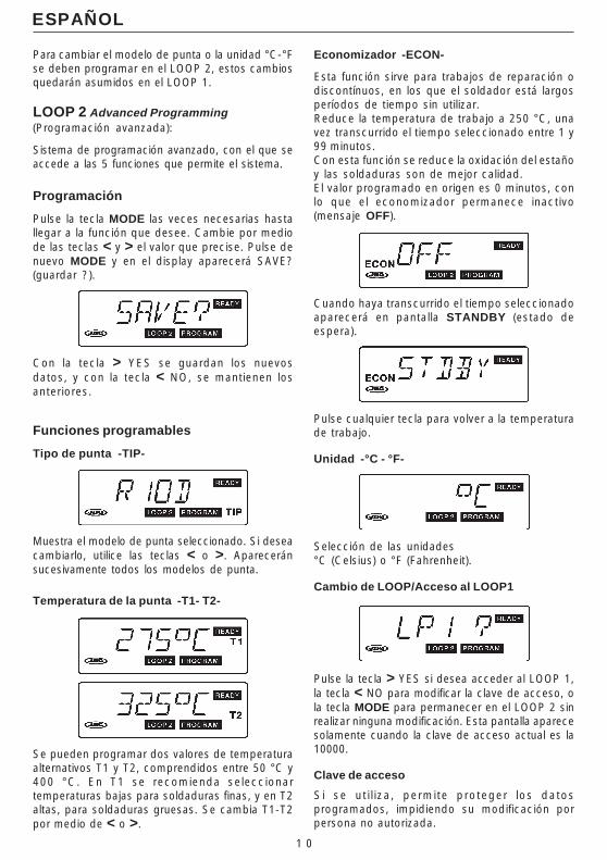
Pulse la tecla MODE las veces necesarias hastallegar a la función que desee. Cambie por mediode las teclas < y > el valor que precise. Pulse denuevo MODE y en el display aparecerá SAVE?(guardar ?).
Con la tecla > YES se guardan los nuevosdatos, y con la tecla < NO, se mantienen losanteriores.
Funciones programables
Tipo de punta -TIP-
Muestra el modelo de punta seleccionado. Si deseacambiarlo, utilice las teclas < o >. Apareceránsucesivamente todos los modelos de punta.
Temperatura de la punta -T1- T2-
Se pueden programar dos valores de temperaturaalternativos T1 y T2, comprendidos entre 50 °C y400 °C. En T1 se recomienda seleccionartemperaturas bajas para soldaduras finas, y en T2altas, para soldaduras gruesas. Se cambia T1-T2por medio de < o >.
Economizador -ECON-
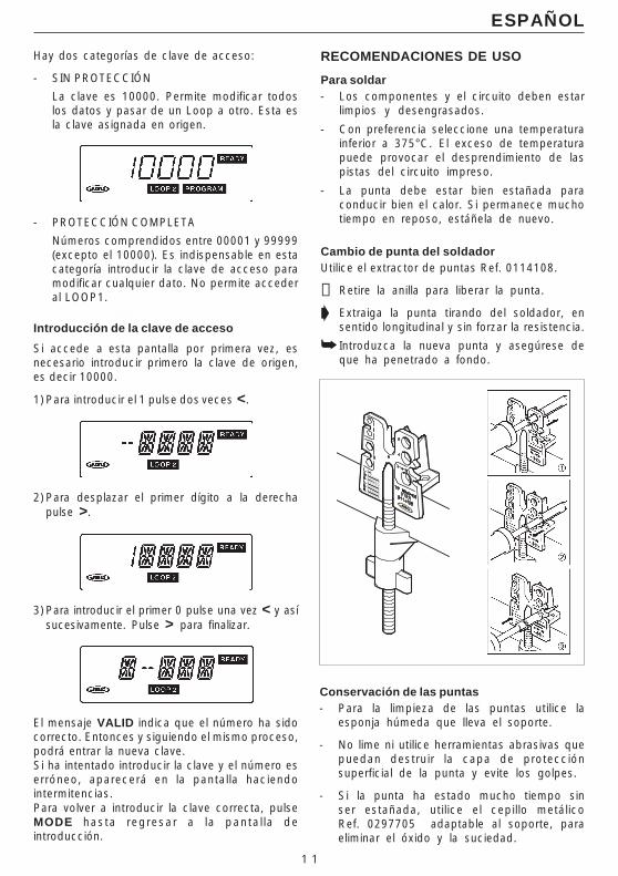
Esta función sirve para trabajos de reparación odiscontínuos, en los que el soldador está largosperíodos de tiempo sin utilizar.Reduce la temperatura de trabajo a 250 °C, unavez transcurrido el tiempo seleccionado entre 1 y99 minutos.Con esta función se reduce la oxidación del estañoy las soldaduras son de mejor calidad.El valor programado en origen es 0 minutos, conlo que el economizador permanece inactivo(mensaje OFF).
Cuando haya transcurrido el tiempo seleccionadoaparecerá en pantalla STANDBY (estado deespera).
Pulse cualquier tecla para volver a la temperaturade trabajo.
Unidad -°C - °F-
Selección de las unidades°C (Celsius) o °F (Fahrenheit).
Cambio de LOOP/Acceso al LOOP1
Pulse la tecla > YES si desea acceder al LOOP 1,la tecla < NO para modificar la clave de acceso, ola tecla MODE para permanecer en el LOOP 2 sinrealizar ninguna modificación. Esta pantalla aparecesolamente cuando la clave de acceso actual es la10000.
Clave de acceso
Si se ut i l iza, permite proteger los datosprogramados, impidiendo su modificación porpersona no autorizada.
1 1
ESPAÑOL
Hay dos categorías de clave de acceso:
- SIN PROTECCIÓN
La clave es 10000. Permite modificar todoslos datos y pasar de un Loop a otro. Esta esla clave asignada en origen.
- PROTECCIÓN COMPLETA
Números comprendidos entre 00001 y 99999(excepto el 10000). Es indispensable en estacategoría introducir la clave de acceso paramodificar cualquier dato. No permite accederal LOOP1.
Introducción de la clave de acceso
Si accede a esta pantalla por primera vez, esnecesario introducir primero la clave de origen,es decir 10000.
1) Para introducir el 1 pulse dos veces <.
2) Para desplazar el primer dígito a la derechapulse >.
3) Para introducir el primer 0 pulse una vez < y asísucesivamente. Pulse > para finalizar.
El mensaje VALID indica que el número ha sidocorrecto. Entonces y siguiendo el mismo proceso,podrá entrar la nueva clave.Si ha intentado introducir la clave y el número eserróneo, aparecerá en la pantalla haciendointermitencias.Para volver a introducir la clave correcta, pulseMODE hasta regresar a la panta l la deintroducción.
RECOMENDACIONES DE USO
Para soldar- Los componentes y el circuito deben estar
limpios y desengrasados.
- Con preferencia seleccione una temperaturainferior a 375°C. El exceso de temperaturapuede provocar el desprendimiento de laspistas del circuito impreso.
- La punta debe estar bien estañada paraconducir bien el calor. Si permanece muchotiempo en reposo, estáñela de nuevo.
Cambio de punta del soldadorUtilice el extractor de puntas Ref. 0114108.
➋ Retire la anilla para liberar la punta.
➧ Extraiga la punta tirando del soldador, ensentido longitudinal y sin forzar la resistencia.
➥ Introduzca la nueva punta y asegúrese deque ha penetrado a fondo.
Conservación de las puntas- Para la limpieza de las puntas utilice la
esponja húmeda que lleva el soporte.
- No lime ni utilice herramientas abrasivas quepuedan destruir la capa de protecciónsuperficial de la punta y evite los golpes.
- Si la punta ha estado mucho tiempo sinser estañada, utilice el cepillo metálicoRef. 0297705 adaptable al soporte, paraeliminar el óxido y la suciedad.
1 2
ESPAÑOL
JBC se reserva el derecho de introducir variaciones técnicassin previo aviso.
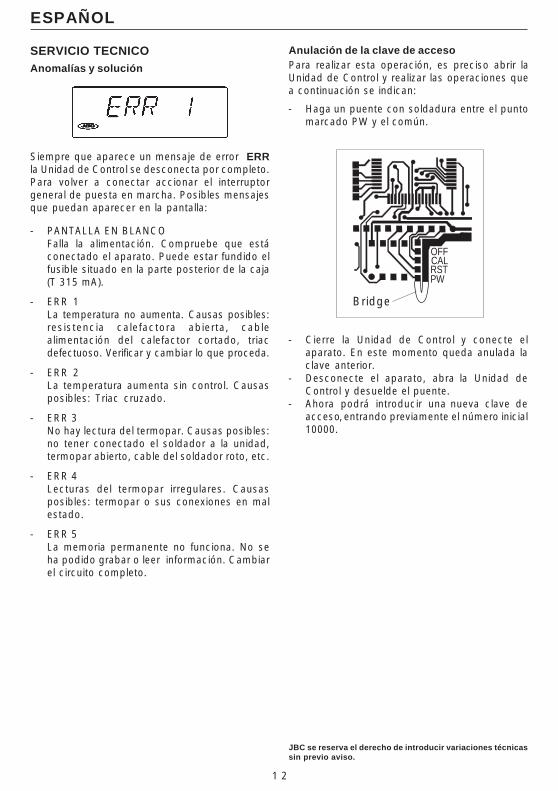
Anulación de la clave de accesoPara realizar esta operación, es preciso abrir laUnidad de Control y realizar las operaciones quea continuación se indican:
- Haga un puente con soldadura entre el puntomarcado PW y el común.
SERVICIO TECNICOAnomalías y solución
Siempre que aparece un mensaje de error ERRla Unidad de Control se desconecta por completo.Para volver a conectar accionar el interruptorgeneral de puesta en marcha. Posibles mensajesque puedan aparecer en la pantalla:
- PANTALLA EN BLANCOFalla la alimentación. Compruebe que estáconectado el aparato. Puede estar fundido elfusible situado en la parte posterior de la caja(T 315 mA).
- ERR 1La temperatura no aumenta. Causas posibles:resistencia calefactora abierta, cablealimentación del calefactor cortado, triacdefectuoso. Verificar y cambiar lo que proceda.
- ERR 2La temperatura aumenta sin control. Causasposibles: Triac cruzado.
- ERR 3No hay lectura del termopar. Causas posibles:no tener conectado el soldador a la unidad,termopar abierto, cable del soldador roto, etc.
- ERR 4Lecturas del termopar irregulares. Causasposibles: termopar o sus conexiones en malestado.
- ERR 5La memoria permanente no funciona. No seha podido grabar o leer información. Cambiarel circuito completo.
Bridge
- Cierre la Unidad de Control y conecte elaparato. En este momento queda anulada laclave anterior.
- Desconecte el aparato, abra la Unidad deControl y desuelde el puente.
- Ahora podrá introducir una nueva clave deacceso, entrando previamente el número inicial10000.
OFFCALRSTPW
13
Nous vous remercions pour la confiance placée dans JBC lors de l'acquisition decette station. Elle a été réalisée avec des hautes performances, avec les plusstrictes normes de qualité. Avant de mettre l'appareil en marche, nous vousconseillons de lire attentivement les instructions qui sont détaillées ci-dessous.
FRANÇAIS
CARACTERISTIQUES
Composition des stationsMD 3050 230V Réf. 3050200:
- Unité de Contrôle Réf. 3430200- Fer à souder 5W
avec panne R-0 D Réf. 3030000- Support fer à souder MS 1300 Réf. 0290130- Manuel d’instructions Réf. 0415470
LD 3100 230V Réf. 3100200:
- Unité de Contrôle Réf. 3130200- Fer à souder 20W
avec panne B-05 D Réf. 3000000- Support fer à souder LS 1100 Réf. 0290110- Manuel d’instructions Réf. 0415470
ID 3110 230V Réf. 3110200:
- Unité de Contrôle Réf. 3130200- Fer à souder 50W
avec panne R-10 D Réf. 3010000- Support fer à souder US 1000 Réf. 0290100- Manuel d’instructions Réf. 0415470
TD 3120 230V Réf. 3120200:
- Unité de Contrôle Réf. 3130200- Fer à souder avec apport
d’étain 60W et panne C-20 D Réf. 3020000- Support fer à souder TS 1200 Réf. 0290120- Manuel d’instructions Réf. 0415470
SD 3140 230V Réf. 3140200:
- Unité de Contrôle Réf. 3730200- Fer à souder 70W
avec panne T-55 D Réf. 3070000- Support fer à souder US 1000 Réf. 0290100- Manuel d’instructions Réf. 0415470
Sur le Unité de Contrôle Réf 3130200 il est possiblede connecter les fers à souder 20, 50, 60 et 70W,bien qu'il soit conseillé d'utiliser ce dernier avecl'Unité de Contrôle Réf. 3730200, spécialementadaptée aux besoins en puissance de ce fer. Surcette dernière unité de contrôle on peut égalementconnecter tous les fers à souder à l'exception du5W qui recquière sa propre Unité de ContrôleRéf. 3430200.
14
Données techniques de l'Unité de Contrôle1. Transformateur de sécurité séparateur du
réseau: LD-ID-TD-SD: 230V/24V 50Hz.MD: 230V/12V 50Hz.
2. Sélection de température entre: 50°C et 400°Cpar intervalles de 1 degré.
3. Précision de la température programmée: ±3%
4. Microprocesseur avec cinq fonctionsprogrammables par l’utilisateur.
5. Sauvegarde de toutes les donnéesprogrammées, même si l 'apparéi l estdébranché.
6. Lecture digitale sur écran LCD.
7. Elle est conforme aux normes CE pour lasécurité électrique, la compatibilité électro-magnétique et la protection antistatique.
8. La prise équipotentielle est connecté à la prisede terre de la fiche d'alimentation de la station.
FRANÇAIS
FONCTIONNEMENT
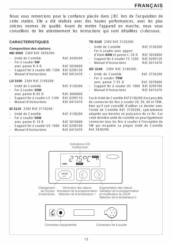
Utilité des touches
< = Diminue valeurs.N (No) = Annule programmation.T1 = Sélection de temperature 1
> = Augmente valeurs.Y (Yes) = Valide programmation et
modifie le LOOP.T2 = Sélection de temperature 2
Passer d’une fonction à une autreet entrer/sortir de programmation.
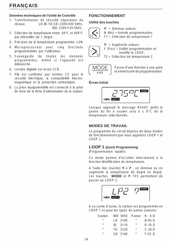
Écran initial
Lorsque apparaît le message READY (prêt) lapanne du fer à souder sera à ± 6°C de latempérature sélectionnée.
MODES DE TRAVAILLe programme du circuit dispose de deux modesde fonctionnement que nous appelons LOOP 1 etLOOP 2.
LOOP 1 Quick Programming(Programmation rapide):
Ce mode permet d’accéder directement à lafonction Modification de température.
A l’aide des touches < e > , on diminue ou onaugmente la température de degré en degré.Les touches MODE et > YES permettent depasser au LOOP 2.
A sa sortie d’usine, la station est programmée enLOOP 1 et pour les types de panne suivants:
Station MD 3050 Panne R- 0 D" LD 3100 " B-05 D" ID 3110 " R-10 D" TD 3120 " C-20 D" SD 3140 " T-55 D

15
16
FRANÇAIS
Pour modifier le modèle de panne ou l’unité °C-°F,introduire les modifications dans le LOOP 2. Ellesseront automatiquement prises en compte par leLOOP 1.
LOOP 2 Advanced Programming(Programmation avancée):
Système de programmation ultra-modernepermettant d’accéder aux 5 fonctions réalisées parle système.
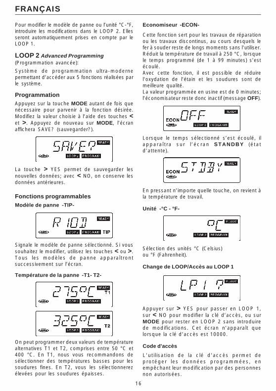
ProgrammationAppuyez sur la touche MODE autant de fois quenécessaire pour parvenir à la fonction désirée.Modifiez la valeur choisie à l’aide des touches <et >. Appuyez de nouveau sur MODE, l’écranaffichera SAVE? (sauvegarder?).
La touche > YES permet de sauvegarder lesnouvelles données; avec < NO, on conserve lesdonnées antérieures.
Fonctions programmablesModèle de panne -TIP-
Signale le modèle de panne sélectionné. Si voussouhaitez le modifier, utilisez les touches < ou >.Tous les modèles de panne appara î t rontsuccessivement sur l’écran.
Température de la panne -T1- T2-
On peut programmer deux valeurs de températurealternatives T1 et T2, comprises entre 50 °C et400 °C. En T1, nous vous recommandons desélectionner des températures basses pour lessoudures fines. En T2, vous les sélectionnerezélevées pour les soudures épaisses.
Economiseur -ECON-
Cette fonction sert pour les travaux de réparationou les travaux discontinus, au cours desquels lefer à souder reste de longs moments sans l'utiliser.Réduit la température de travail à 250 °C, lorsquele temps programmé (de 1 à 99 minutes) s’estécoulé.Avec cette fonction, il est possible de réduirel'oxydation de l'étain et les soudures sont demeilleure qualité.La valeur programmée en usine est de 0 minutes;l’économisateur reste donc inactif (message OFF).
Lorsque le temps sélectionné s’est écoulé, ilappara î t ra su r l ’ éc ran STANDBY ( é ta td’attente).
En pressant n’importe quelle touche, on revient àla température de travail.
Unité -°C - °F-
Sélection des unités °C (Celsius)ou °F (Fahrenheit).
Change de LOOP/Accès au LOOP 1
Appuyer sur > YES pour passer en LOOP 1,sur < NO pour modifier la clé d’accès, ou surMODE pour rester en LOOP 2 sans introduirede modifications. Cet écran n’apparaît quelorsque la clé d’accès est 10000.
Code d'accès
L'ut i l isat ion de la c lé d'accès permet depro tége r l es données p rogrammées , enempêchant leur modification par des personnesnon autorisées.
17
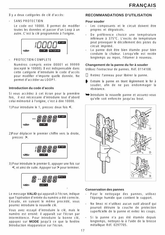
Il y a deux catégories de clé d'accès:
- SANS PROTECTION
Le code est 10000. Il permet de modifiertoutes les données et passer d'un Loop à unautre. C'est la clé programmée à l'origine.
- PROTECTION COMPLETE
Numéros compris entre 00001 et 99999(excepté le 10000). Il est indispensable danscette catégorie d’introduire le code d’accèspour modifier n’importe quelle donnée. Nepermet d’accéder au LOOP1.
Introduction du code d’accès
Si vous accédez à cet écran pour la premièrefois, il est nécessaire d’introduire tout d’abordcelui mémorisé à l’origine, c’est à dire 10000.
1) Pour introduire le 1, pressez deux fois <.
2)Pour déplacer le premier chiffre vers la droite,pressez >.
3) Pour introduire le premier 0, appuyer une fois sur<, et ainsi de suite. Appuyer sur > pour terminer.
Le message VALID qui apparaît à l’écran, indiqueque l’opération d’entrée du numéro a été correcte.Ensuite, en suivant le même procédé, vouspourrez introduire la nouvelle clé.
Vous avez essayé d’introduire la clé, mais lenuméro est erroné: il apparaît sur l’écran parintermittence. Pour introduire la bonne clé,appuyez sur MODE jusqu’à ce que la fenêtreIntroduction réapparaisse sur l’écran.
FRANÇAIS
RECOMMANDATIONS D’UTILISATION
Pour souder- Les composants et le circuit doivent être
propres et dégraissés.
- De préférence choisir une températureinférieure à 375°C. L’excès de températurepeut provoquer le décollement des pistes ducircuit imprimé.
- La panne doit être bien étamée pour bienconduire la chaleur. Lorsqu’elle est restéelongtemps au repos, l’étamer à nouveau.
Changement de la panne du fer à souderUtilisez l’extracteur de pannes. Réf. 0114108.
➋ Retirez l’anneau pour libérer la panne.
➧ Extraire la panne en tirant légèrement le fer àsouder, afin de ne pas endommager larésistance.
➥ Introduire la nouvelle panne et assurez-vousqu'elle soit enfoncée jusqu’au bout.
Conservation des pannes- Pour le nettoyage des pannes, uti l isez
l’éponge humide que contient le support.
- Ne limez ni n’utilisez aucun outil abrasif quipourrait détruire la couche de protectionsuperficielle de la panne et evitez les coups.
- Si la panne n'a pas été étamée depuislongtemps, nettoyez-la à l'aide de la brossemétallique Réf. 0297705.
18
FRANÇAIS
JBC se réserve le droit d'introduire des variations techniquesou de conception sans préavis.
SERVICE TECHNIQUEAnomalies et solution
Chaque fois qu’il apparaît un message d’erreurERR , l ’Uni té de Contrô le se débranchecomplètement Pour la brancher à nouveau,actionnez l’interrupteur général de mise enmarche. Les messages suivants poiventapparaître à l’écran :
- ECRAN BLANCPanne d’alimentation. Vérifiez que l'apparéilest connecté et si le fusible situé dans lapartie postérieure du boîtier n’est pas fondu(T 315 mA).
- ERR 1La température n'augmente pas ou le débitd'air est très bas. Causes possibles :rés istance chauf fage ouverte, câbled'alimentation du chauffage coupé, triacdéfectueux. Vérifiez et changez ce qu’ilconvient.
- ERR 2La température augmente sans contrôle.Causes possibles : Triac croisé.
- ERR 3Absence de lecture du thermocouple. Causespossibles: le fer à souder n’est pas branchéà l'Unité, thermocouple ouvert, câble deconnexion du thermocouple cassé.
- ERR 4Lectures du thermocouple irrégulières. Causespossibles: thermocouple ou ses connexionsen mauvais état.
- ERR 5La mémoire permanente ne fonctionne pas.On n'a pas pu enregistrer ou lire l'information.Changer le circuit complet.
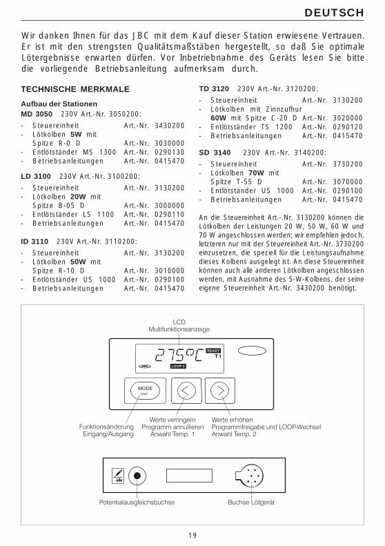
Annulation du code d’accèsPour réaliser cette opération, il faut ouvrir l’Unitéde Contrôle et suivre les indications suivantes:
- Faites un pont de soudure entre le pointmarqué PW et le point commun.
- Fermez l’Unité de Contrôle et branchezl’appareil. La clé antérieure est désormaisannulée.
- Débranchez l’appareil, ouvrez l’Unité deContrôle et dessoudez le pont.
- Vous pouvez à présent introduire une nouvelleclé d’accès, après avoir introduit le numéroinitial 10000.
OFFCALRSTPW
Bridge
19
Wir danken Ihnen für das JBC mit dem Kauf dieser Station erwiesene Vertrauen.Er ist mit den strengsten Qualitätsmaßstäben hergestellt, so daß Sie optimaleLötergebnisse erwarten dürfen. Vor Inbetriebnahme des Geräts lesen Sie bittedie vorliegende Betriebsanleitung aufmerksam durch.
DEUTSCH
TECHNISCHE MERKMALE
Aufbau der StationenMD 3050 230V Art.-Nr. 3050200:
- Steuereinheit Art.-Nr. 3430200- Lötkolben 5W mit
Spitze R-0 D Art.-Nr. 3030000- Entlötständer MS 1300 Art.-Nr. 0290130- Betriebsanleitungen Art.-Nr. 0415470
LD 3100 230V Art.-Nr. 3100200:
- Steuereinheit Art.-Nr. 3130200- Lötkolben 20W mit
Spitze B-05 D Art.-Nr. 3000000- Entlötständer LS 1100 Art.-Nr. 0290110- Betriebsanleitungen Art.-Nr. 0415470
ID 3110 230V Art.-Nr. 3110200:
- Steuereinheit Art.-Nr. 3130200- Lötkolben 50W mit
Spitze R-10 D Art.-Nr. 3010000- Entlötständer US 1000 Art.-Nr. 0290100- Betriebsanleitungen Art.-Nr. 0415470
TD 3120 230V Art.-Nr. 3120200:
- Steuereinheit Art.-Nr. 3130200- Lötkolben mit Zinnzufhur
60W mit Spitze C-20 D Art.-Nr. 3020000- Entlötständer TS 1200 Art.-Nr. 0290120- Betriebsanleitungen Art.-Nr. 0415470
SD 3140 230V Art.-Nr. 3140200:
- Steuereinheit Art.-Nr. 3730200- Lötkolben 70W mit
Spitze T-55 D Art.-Nr. 3070000- Entlötständer US 1000 Art.-Nr. 0290100- Betriebsanleitungen Art.-Nr. 0415470
An die Steuereinheit Art.-.Nr. 3130200 können dieLötkolben der Leistungen 20 W, 50 W, 60 W und70 W angeschlossen werden; wir empfehlen jedoch,letzteren nur mit der Steuereinheit Art.-Nr. 3730200einzusetzen, die speziell für die Leistungsaufnahmedieses Kolbens ausgelegt ist. An diese Steuereinheitkönnen auch alle anderen Lötkolben angeschlossenwerden, mit Ausnahme des 5-W-Kolbens, der seineeigene Steuereinheit Art.-Nr. 3430200 benötigt.
20
Technische Angaben1. Sicherheitstransformator mit Netztrennung:
LD-ID-TD-SD: 230V/24V 50Hz. MD: 230V/12V 50Hz.
2. Temperaturwahl zwischen: 50°C und 400°Cund kann in Schritten von 1°C variiert werden.
3. Genauigkeit der eingestellten Temp.: ± 3%
4. Microprocessor mit 5 programmierbarenFunktionen.
5. Bewahrt alle programmierte Daten auf, auchwenn abgeschaltet.
6. Digital an-zeige auf LCD-Display ablesbar.
7. Erfüllt die Sicherheitsvorschriften der CE überelektrische Sicherheit, elektromagnetischeKompatibilität und antistatischer Schutz.
8. Die Equipotentialausgleichsbuchse ist mit derErdung des Netzsteckers verbunden.
DEUTSCH
BETRIEB
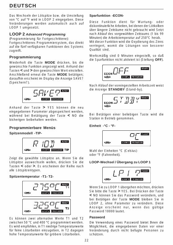
Zweck der Tasten
< = Verringerung der Werte.N (No) = Programmierung außer Kraft.T1 = Temperaturwahl 1
> = Erhöhung der Werte.Y (Yes) = Programmierung in Kraft
und LOOP-Wechsel.T2 = Temperaturwahl 2
Übergang von einer Funktionzu r anderen ; Beg inn /EndeProgrammierung.
Anfangsanzeige
Wenn im Display d ie Anzeige READY(betriebsbereit) erscheint, hat sich die Spitze aufden vorgewählten Wert (mit einer Toleranz von± 6°C) erwärmt.
ARBEITSREGIMESDas Programm des Schaltkreises bietet zweiFunktionsweisen, die wir LOOP 1 und LOOP 2(Schleife) nennen.
LOOP 1 Quick Programming(Schnellprogrammierung):
In diesem Regime hat man direkten Zugang zurFunktion Temperaturänderung.Die Tasten < und > erlauben eine gradweiseVerringerung bzw. Erhöhung der Temperatur;anhand der Tasten MODE und > YES erfolgtder Übergang zu LOOP 2.
Die Station ist werksmäßig auf LOOP 1 undfolgende Spitzenmodelle programmiert:
Station MD 3050 Spitze R- 0 D" LD 3100 " B-05 D" ID 3110 " R-10 D" TD 3120 " C-20 D" SD 3140 " T-55 D

21
22
DEUTSCH
Das Wechseln der Lötspitze bzw. die Umstellungvon °C auf °F wird in LOOP 2 eingegeben. DieseVeränderungen werden automatisch auch aufLOOP 1 umgesetzt.
LOOP 2 Advanced Programming(Programmierung für Fortgeschrittene):Fortgeschrittenes Programmiersystem, das direktauf die fünf verfügbaren Funktionen des Systemszugreift.
ProgrammierungWiederholt die Taste MODE drücken, bis diegewünschte Funktion angezeigt wird. Anhand derTasten < und > den gewünschten Wert einstellen.Anschließend erneut die Taste MODE betätigen;daraufhin erscheint im Display die Anzeige SAVE?(Speichern?).
Anhand der Taste > YES können die neueingegebenen Parameter abgespeichert werden,während bei Betätigung der Taste < NO diebisherigen beibehalten werden.
Programmierbare MenüsSpitzenmodell -TIP-
Zeigt die gewählte Lötspitze an. Wenn Sie dieLötspitze auswechseln wollen, drücken Sie dieTasten < oder >. Es erscheinen der Reihe nachalle Lötspitzentypen.
Spitzentemperatur -T1- T2-
Es können zwei alternative Werte T1 und T2zwischen 50 °C und 400 °C programmiert werden.Es wird empfohlen, in T1 niedrige Temperaturwertefür feine Lötarbeiten einzugeben, in T2 dagegenhohe Temperaturwerte für gröbere Lötarbeiten.
Sparfunktion -ECON-
Diese Funktion dient für Wartung- oderdiskontinuierliche Arbeiten, bei denen der Lötkolbenüber längere Zeiträume nicht gebraucht wird Setztnach Ablauf des vorgewählten Zeitraums (1 bis 99Minuten) die Arbeitstemperatur auf 250°C herab.Mit dieser Funktion wird die Oxydierung des Zinnsverringert, womit die Lötungen von bessererQualität sind.
Werksmäßig sind 0 Minuten eingestellt, so daßdie Sparfunktion nicht aktiviert ist (Stellung OFF).
Nach Ablauf der voreingestellten Arbeitszeit weistdie Anzeige STANDBY (Stand-by).
Bei Betätigen einer beliebigen Taste wird dieStation in Betrieb genommen.
Einheit -°C - °F-
Wahl der Einheiten °C (Celsius)oder °F (Fahrenheit).
LOOP-Wechsel / Übergang zu LOOP 1
Wenn Sie zu LOOP 1 übergehen möchten, drückenSie bitte die Taste > YES. Bei Drücken der Taste< NO können Sie das Password verändern, undbei Betätigen der Taste MODE bleiben Sie inLOOP 2, ohne Parameter zu verändern. DieseAnzeige erscheint nur, wenn das gül t igePassword 10000 lautet.
Password
Die Verwendung eines Password bietet Ihnen dieMöglichkeit, die eingegebenen Daten vor einerVeränderung durch nicht befugte Personen zuschützen.
23
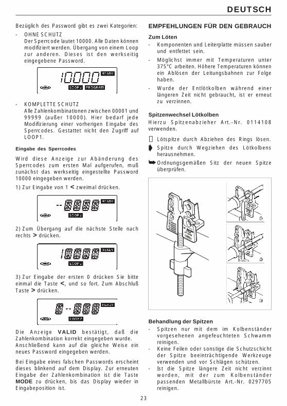
Bezüglich des Password gibt es zwei Kategorien:
- OHNE SCHUTZDer Sperrcode lautet 10000. Alle Daten könnenmodifiziert werden. Übergang von einem Loopzur anderen. Dieses ist den werkseit igeingegebene Password.
- KOMPLETTE SCHUTZAlle Zahlenkombinationen zwischen 00001 und99999 (außer 10000). Hier bedarf jedeModifizierung einer vorherigen Eingabe desSperrcodes. Gestattet nicht den Zugriff aufLOOP1.
Eingabe des Sperrcodes
Wird diese Anzeige zur Abänderung desSperrcodes zum ersten Mal aufgerufen, mußzunächst das werkseitig eingestellte Password10000 eingegeben werden.
1) Zur Eingabe von 1 < zweimal drücken.
2) Zum Übergang auf die nächste Stelle nachrechts > drücken.
3) Zur Eingabe der ersten 0 drücken Sie bitteeinmal die Taste <, und so fort. Zum AbschlußTaste > drücken.
Die Anzeige VALID bestät igt , daß dieZahlenkombination korrekt eingegeben wurde.Anschließend kann auf die gleiche Weise einneues Password eingegeben werden.
Bei Eingabe eines falschen Passwords erscheintdieses blinkend auf dem Display. Zur erneutenEingabe der Zahlenkombination ist die TasteMODE zu drücken, bis das Display wieder inEingabeposition ist.
DEUTSCH
EMPFEHLUNGEN FÜR DEN GEBRAUCH
Zum Löten- Komponenten und Leiterplatte müssen sauber
und entfettet sein.
- Möglichst immer mit Temperaturen unter375°C arbeiten. Höhere Temperaturen könnenein Ablösen der Leitungsbahnen zur Folgehaben.
- Wurde der Entlötkolben während einerlängeren Zeit nicht gebraucht, ist er erneutzu verzinnen.
Spitzenwechsel LötkolbenHierzu Spi tzenabzieher Art .-Nr. 0114108verwenden.
➋ Lötspitze durch Abziehen des Rings lösen.
➧ Spitze durch Wegziehen des Lötkolbensherausnehmen.
➥ Ordnungsgemäßen Sitz der neuen Spitzeüberprüfen.
Behandlung der Spitzen- Spitzen nur mit dem im Kolbenständer
vorgesehenen angefeuchteten Schwammreinigen.
- Keine Feilen oder sonstige die Schutzschichtder Spitze beeinträchtigende Werkzeugeverwenden und vor Schlägen schützen.
- Ist die Spitze längere Zeit nicht verzinntworden, mit der zum Kolbenständerpassenden Metallbürste Art.-Nr. 0297705reinigen.
24
Technische und konstruktive Änderungen vorbehalten.
DEUTSCH
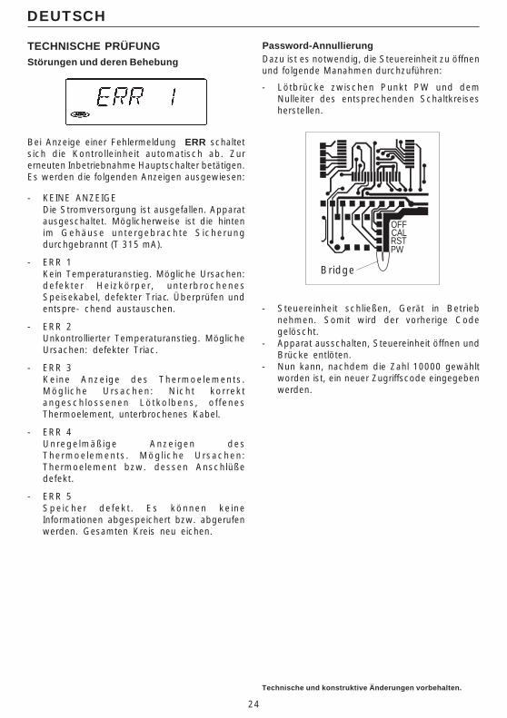
TECHNISCHE PRÜFUNGStörungen und deren Behebung
Bei Anzeige einer Fehlermeldung ERR schaltetsich die Kontrolleinheit automatisch ab. Zurerneuten Inbetriebnahme Hauptschalter betätigen.Es werden die folgenden Anzeigen ausgewiesen:
- KEINE ANZEIGEDie Stromversorgung ist ausgefallen. Apparatausgeschaltet. Möglicherweise ist die hintenim Gehäuse untergebrachte Sicherungdurchgebrannt (T 315 mA).
- ERR 1Kein Temperaturanstieg. Mögliche Ursachen:defekter Heizkörper, unterbrochenesSpeisekabel, defekter Triac. Überprüfen undentspre- chend austauschen.
- ERR 2Unkontrollierter Temperaturanstieg. MöglicheUrsachen: defekter Triac.
- ERR 3Keine Anzeige des Thermoelements.Mögl iche Ursachen: Nicht korrektangeschlossenen Lötkolbens, of fenesThermoelement, unterbrochenes Kabel.
- ERR 4Unregelmäßige Anzeigen desThermoelements. Mögl iche Ursachen:Thermoelement bzw. dessen Anschlüßedefekt.
- ERR 5Speicher defekt . Es können keineInformationen abgespeichert bzw. abgerufenwerden. Gesamten Kreis neu eichen.
Password-AnnullierungDazu ist es notwendig, die Steuereinheit zu öffnenund folgende Manahmen durchzuführen:
- Lötbrücke zwischen Punkt PW und demNulleiter des entsprechenden Schaltkreisesherstellen.
Bridge
- Steuereinheit schließen, Gerät in Betriebnehmen. Somit wird der vorherige Codegelöscht.
- Apparat ausschalten, Steuereinheit öffnen undBrücke entlöten.
- Nun kann, nachdem die Zahl 10000 gewähltworden ist, ein neuer Zugriffscode eingegebenwerden.
OFFCALRSTPW
25
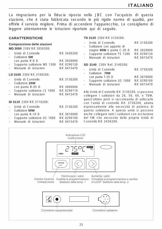
La ringraziamo per la fiducia riposta nella JBC con l'acquisto di questastazione, che è stata fabbricata secondo le più rigide norme di qualità, peroffrirle il servizio migliore. Prima di accendere l'apparecchio, Le consigliamo dileggere attentamente le istruzioni riportate qui di seguito.
ITALIANO
CARATTERISTICHE
Composizione delle stazioniMD 3050 230V Rif. 3050200:
- Unità di Controllo Rif. 3430200- Saldatore 5W
con punta R-0 D Rif. 3030000- Supporto saldatore MS 1300 Rif. 0290130- Manuale di istruzioni Rif. 0415470
LD 3100 230V Rif. 3100200:
- Unità di Controllo Rif. 3130200- Saldatore 20W
con punta B-05 D Rif. 3000000- Supporto saldatore LS 1000 Rif. 0290110- Manuale di istruzioni Rif. 0415470
ID 3110 230V Rif. 3110200:
- Unità di Controllo Rif. 3130200- Saldatore 50W
con punta R-10 D Rif. 3010000- Supporto saldatore US 1000 Rif. 0290100- Manuale di istruzioni Rif. 0415470
TD 3120 230V Rif. 3120200:
- Unità di Controllo Rif. 3130200- Saldatore con apporto di
stagno 60W e punta C-20 D Rif. 3020000- Supporto saldatore TS 1200 Rif. 0290120- Manuale di istruzioni Rif. 0415470
SD 3140 230V Ref. 3140200:
- Unità di Controllo Rif. 3730200- Saldatore 70W
con punta T-55 D Rif. 3070000- Supporto saldatore US 1000 Rif. 0290100- Manuale di istruzioni Rif. 0415470
Alle Unità di Controllo Rif. 3130200, si possonocollegare i saldatori da 20, 50, 60, e 70W,quest'ultimo però si raccomanda di utilizzarlocon l'unità di controllo Rif. 3730200, adattaespressamente alla necessità di potenza diquesto saldatore. A questa unità si possonoanche collegare tutti i saldatori con esclusionedel 5W che necessita della propria Unità diControllo Rif. 3430200.
26
Dati tecnici dell’Unità di Controllo1. Trasformatore di sicurezza con isolamento
della rete: LD-ID-TD-SD: 230V/24V 50Hz.MD: 230V/12V 50Hz.
2. Selezione di temperatura tra 50 e 400°C:ad intervalli di un grado.
3. Precisione della temp. programmata: ±3%
4. Microprocessore con c inque funz ioniprogrammabili dall’utente.
5. Conservazione di tutti i dati programmati,persino ad apparecchio spento.
6. Lettura digitale mediante display LCD.
7. Assolve la normativa CE riguardante lasicurezza elettrica, compatibilita' electtro-magnetica e protezione antistatica.
8. Il connettore equipotenziale è collegato allapresa di terra della spina.
ITALIANO
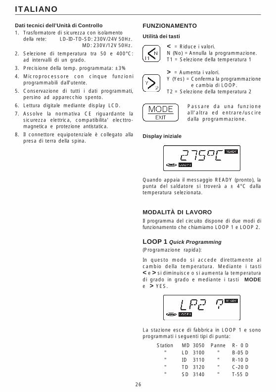
FUNZIONAMENTO
Utilità dei tasti
< = Riduce i valori.N (No) = Annulla la programmazione.T1 = Selezione della temperatura 1
> = Aumenta i valori.Y (Yes) = Conferma la programmazione
e cambia di LOOP.T2 = Selezione della temperatura 2
Passare da una funz ionea l l ’a l t ra ed ent rare/usc i redalla programmazione.
Display iniziale
Quando appaia il messaggio READY (pronto), lapunta del saldatore si troverà a ± 4°C dallatemperatura selezionata.
MODALITÀ DI LAVOROIl programma del circuito dispone di due modi difunzionamento che chiamiamo LOOP 1 e LOOP 2.
LOOP 1 Quick Programming(Programazione rapida):
In questo modo si accede direttamente alcambio della temperatura. Mediante i tasti< e > si diminuisce o si aumenta la temperaturadi grado in grado e mediante i tasti MODEe > YES.
La stazione esce di fabbrica in LOOP 1 e sonoprogrammati i seguenti tipi di punta:
Station MD 3050 Panne R- 0 D" LD 3100 " B-05 D" ID 3110 " R-10 D" TD 3120 " C-20 D" SD 3140 " T-55 D

27
28
ITALIANO
Per cambiare il modello di punta o l’unità di misura(°C o °F), questi dati devono essere programmatinel LOOP 2, e saranno automaticamente acquisitinel LOOP 1.
LOOP 2 Advanced Programming(Programazione avanzata):Sistema di programmazione avanzata, con cui siaccede alle 5 funzioni permesse dal sistema.
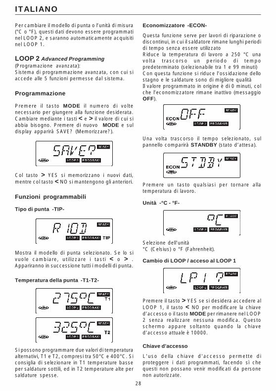
Programmazione
Premere i l tasto MODE i l numero di voltenecessario per giungere alla funzione desiderata.Cambiare mediante i tasti < e > il valore di cui siabbia bisogno. Premere di nuovo MODE e suldisplay apparirà SAVE? (Memorizzare?).
Col tasto > YES si memorizzano i nuovi dati,mentre col tasto < NO si mantengono gli anteriori.
Funzioni programmabili
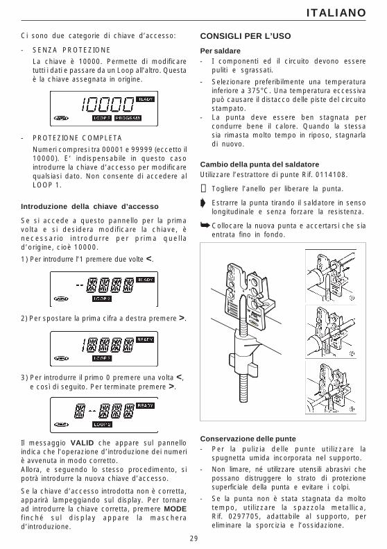
Tipo di punta -TIP-
Mostra il modello di punta selezionato. Se lo sivuole cambiare, ut i l izzare i tast i < o > .Appariranno in successione tutti i modelli di punta.
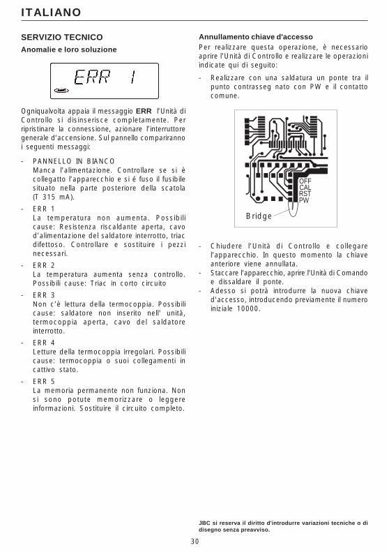
Temperatura della punta -T1-T2-
Si possono programmare due valori di temperaturaalternativi, T1 e T2, compresi tra 50°C e 400°C. Siconsiglia di selezionare in T1 temperature basseper saldature sottili, ed in T2 temperature alte persaldature spesse.
Economizzatore -ECON-
Questa funzione serve per lavori di riparazione odiscontinui, in cui il saldatore rimane lunghi periodidi tempo senza essere utilizzatoRiduce la temperatura di lavoro a 250 °C unavol ta t rascorso un per iodo di tempopredeterminato (selezionabile tra 1 e 99 minuti)Con questa funzione si riduce l'ossidazione dellostagno e le saldature sono di migliore qualitàIl valore programmato in origine è di 0 minuti, colche l’economizzatore rimane inattivo (messaggioOFF).
Una volta trascorso il tempo selezionato, sulpannello comparirà STANDBY (stato d’attesa).
Premere un tasto qualsiasi per tornare allatemperatura di lavoro.
Unità -°C - °F-
Selezione dell'unità°C (Celsius) o °F (Fahrenheit).
Cambio di LOOP / acceso al LOOP 1
Premere il tasto > YES se si desidera accedere alLOOP 1, il tasto < NO per modificare la chiaved’accesso o il tasto MODE per rimanere nel LOOP2 senza realizzare nessuna modifica. Questoschermo appare soltanto quando la chiaved’accesso attuale è 10000.
Chiave d’accesso
L'uso del la chiave d'accesso permette diproteggere i dati programmati, facendo sì chequesti non possano venir modificati da personenon autorizzate.
29
ITALIANO
Ci sono due categorie di chiave d’accesso:
- SENZA PROTEZIONE
La chiave è 10000. Permette di modificaretutti i dati e passare da un Loop all'altro. Questaè la chiave assegnata in origine.
- PROTEZIONE COMPLETA
Numeri compresi tra 00001 e 99999 (eccetto il10000). E‘ indispensabile in questo casointrodurre la chiave d’accesso per modificarequalsiasi dato. Non consente di accedere alLOOP 1.
Introduzione della chiave d’accesso
Se si accede a questo pannello per la primavolta e si desidera modificare la chiave, ènecessa r io i n t rodur re pe r p r ima que l l ad’origine, cioè 10000.
1) Per introdurre l’1 premere due volte <.
2) Per spostare la prima cifra a destra premere >.
3) Per introdurre il primo 0 premere una volta <,e così di seguito. Per terminate premere >.
Il messaggio VALID che appare sul pannelloindica che l’operazione d’introduzione dei numeriè avvenuta in modo corretto.Allora, e seguendo lo stesso procedimento, sipotrà introdurre la nuova chiave d’accesso.
Se la chiave d’accesso introdotta non è corretta,apparirà lampeggiando sul display. Per tornaread introdurre la chiave corretta, premere MODEf inché sul d isplay appare la mascherad’introduzione.
CONSIGLI PER L’USO
Per saldare- I componenti ed il circuito devono essere
puliti e sgrassati.
- Selezionare preferibilmente una temperaturainferiore a 375°C. Una temperatura eccessivapuò causare il distacco delle piste del circuitostampato.
- La punta deve essere ben stagnata percondurre bene il calore. Quando la stessasia rimasta molto tempo in riposo, stagnarladi nuovo.
Cambio della punta del saldatoreUtilizzare l’estrattore di punte Rif. 0114108.
➋ Togliere l’anello per liberare la punta.
➧ Estrarre la punta tirando il saldatore in sensolongitudinale e senza forzare la resistenza.
➥ Collocare la nuova punta e accertarsi che siaentrata fino in fondo.
Conservazione delle punte- Per la pul izia del le punte uti l izzare la
spugnetta umida incorporata nel supporto.
- Non limare, né utilizzare utensili abrasivi chepossano distruggere lo strato di protezionesuperficiale della punta e evitare i colpi.
- Se la punta non è stata stagnata da moltotempo, uti l izzare la spazzola metall ica,Rif. 0297705, adattabile al supporto, pereliminare la sporcizia e l’ossidazione.
30
ITALIANO
JBC si reserva il diritto d'introdurre variazioni tecniche o didisegno senza preavviso.
SERVIZIO TECNICOAnomalie e loro soluzione
Ogniqualvolta appaia il messaggio ERR l’Unità diControllo si disinserisce completamente. Perripristinare la connessione, azionare l’interruttoregenerale d’accensione. Sul pannello comparirannoi seguenti messaggi:
- PANNELLO IN BIANCOManca l’alimentazione. Controllare se si ècollegatto l’apparecchio e si é fuso il fusibilesituato nella parte posteriore della scatola(T 315 mA).
- ERR 1La temperatura non aumenta. Possibil icause: Resistenza riscaldante aperta, cavod’alimentazione del saldatore interrotto, triacdifettoso. Controllare e sostituire i pezzinecessari.
- ERR 2La temperatura aumenta senza controllo.Possibili cause: Triac in corto circuito
- ERR 3Non c’è lettura della termocoppia. Possibilicause: saldatore non inserito nell' unità,termocoppia aperta, cavo del saldatoreinterrotto.
- ERR 4Letture della termocoppia irregolari. Possibilicause: termocoppia o suoi collegamenti incattivo stato.
- ERR 5La memoria permanente non funziona. Nonsi sono potute memorizzare o leggereinformazioni. Sostituire il circuito completo.
Annullamento chiave d'accessoPer realizzare questa operazione, è necessarioaprire l'Unità di Controllo e realizzare le operazioniindicate qui di seguito:
- Realizzare con una saldatura un ponte tra ilpunto contrasseg nato con PW e il contattocomune.
- Chiudere l'Unità di Controllo e collegarel'apparecchio. In questo momento la chiaveanteriore viene annullata.
- Staccare l'apparecchio, aprire l'Unità di Comandoe dissaldare il ponte.
- Adesso si potrà introdurre la nuova chiaved'accesso, introducendo previamente il numeroiniziale 10000.
Bridge
OFFCALRSTPW
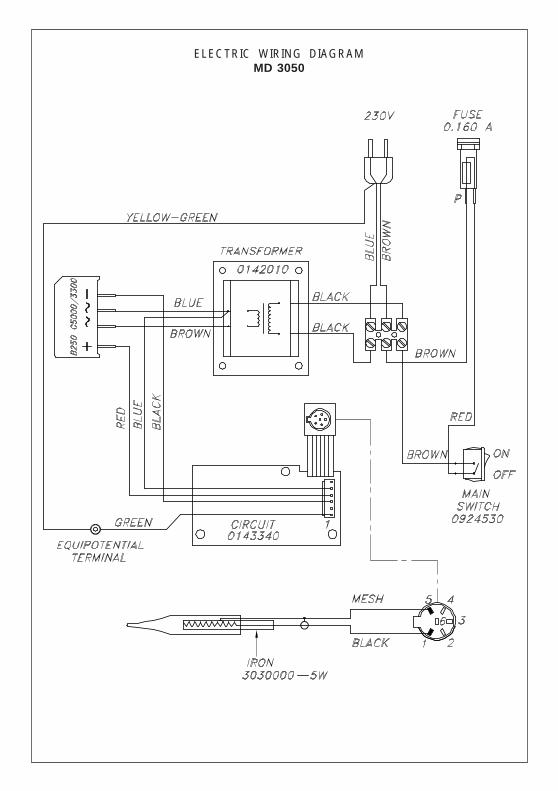
ELECTRIC WIRING DIAGRAMMD 3050
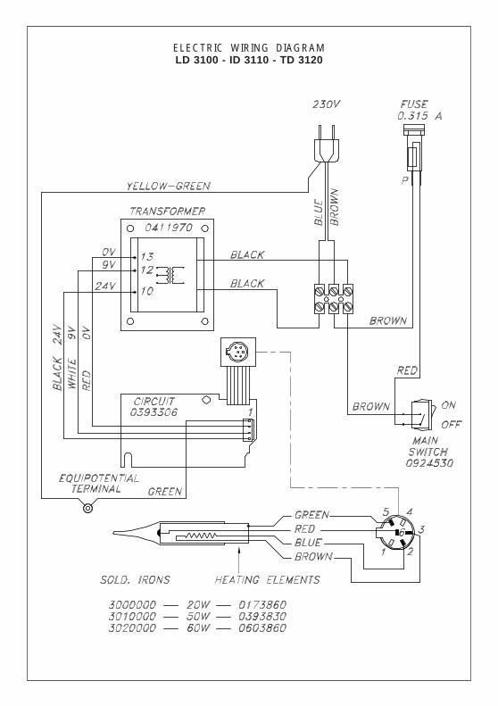
ELECTRIC WIRING DIAGRAMLD 3100 - ID 3110 - TD 3120
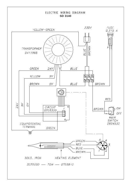
ELECTRIC WIRING DIAGRAMSD 3140
1 Kupferkern2 Eisen3 Nickel4 Chrom5 Verzinnung
1 Nucleo di rame2 Ferro3 Nichel4 Cromo5 Stagnatura
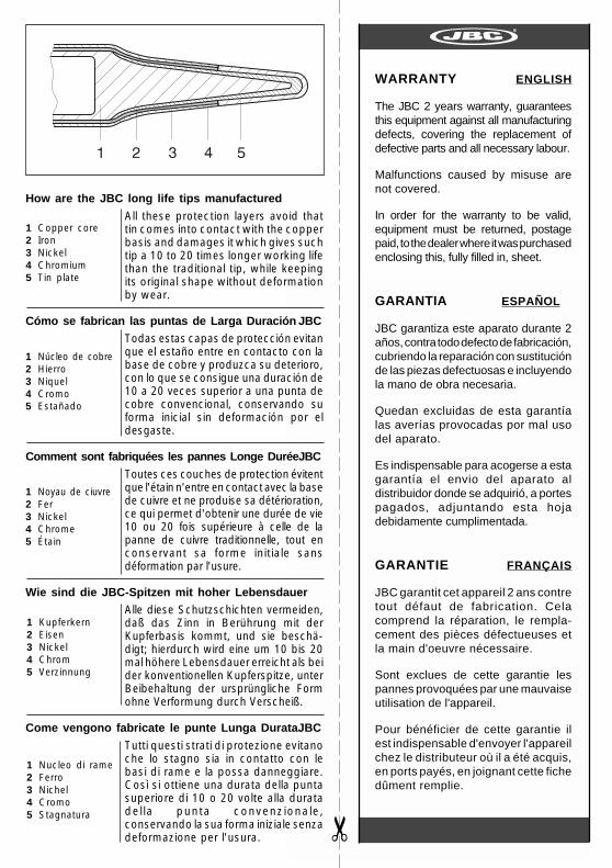
How are the JBC long life tips manufactured
All these protection layers avoid thattin comes into contact with the copperbasis and damages it which gives suchtip a 10 to 20 times longer working lifethan the traditional tip, while keepingits original shape without deformationby wear.
Cómo se fabrican las puntas de Larga Duración JBC
Todas estas capas de protección evitanque el estaño entre en contacto con labase de cobre y produzca su deterioro,con lo que se consigue una duración de10 a 20 veces superior a una punta decobre convencional, conservando suforma inicial sin deformación por eldesgaste.
Comment sont fabriquées les pannes Longe DuréeJBC
Toutes ces couches de protection évitentque l'étain n'entre en contact avec la basede cuivre et ne produise sa détérioration,ce qui permet d'obtenir une durée de vie10 ou 20 fois supérieure à celle de lapanne de cuivre traditionnelle, tout enconservant sa forme initiale sansdéformation par l'usure.
Wie sind die JBC-Spitzen mit hoher Lebensdauer
Alle diese Schutzschichten vermeiden,daß das Zinn in Berührung mit derKupferbasis kommt, und sie beschä-digt; hierdurch wird eine um 10 bis 20mal höhere Lebensdauer erreicht als beider konventionellen Kupferspitze, unterBeibehaltung der ursprüngliche Formohne Verformung durch Verscheiß.
Come vengono fabricate le punte Lunga DurataJBC
Tutti questi strati di protezione evitanoche lo stagno sia in contatto con lebasi di rame e la possa danneggiare.Così si ottiene una durata della puntasuperiore di 10 o 20 volte alla duratadel la punta convenzionale,conservando la sua forma iniziale senzadeformazione per l'usura.
1 Copper core2 Iron3 Nickel4 Chromium5 Tin plate
1 Núcleo de cobre2 Hierro3 Niquel4 Cromo5 Estañado
1 Noyau de ciuvre2 Fer3 Nickel4 Chrome5 Étain
✂
WARRANTY ENGLISH
The JBC 2 years warranty, guaranteesthis equipment against all manufacturingdefects, covering the replacement ofdefective parts and all necessary labour.
Malfunctions caused by misuse arenot covered.
In order for the warranty to be valid,equipment must be returned, postagepaid, to the dealer where it was purchasedenclosing this, fully filled in, sheet.
GARANTIA ESPAÑOL
JBC garantiza este aparato durante 2años, contra todo defecto de fabricación,cubriendo la reparación con sustituciónde las piezas defectuosas e incluyendola mano de obra necesaria.
Quedan excluidas de esta garantíalas averías provocadas por mal usodel aparato.
Es indispensable para acogerse a estagarantía el envio del aparato aldistribuidor donde se adquirió, a portespagados, adjuntando esta hojadebidamente cumplimentada.
GARANTIE FRANÇAIS
JBC garantit cet appareil 2 ans contretout défaut de fabrication. Celacomprend la réparation, le rempla-cement des pièces défectueuses etla main d'oeuvre nécessaire.
Sont exclues de cette garantie lespannes provoquées par une mauvaiseutilisation de l'appareil.
Pour bénéficier de cette garantie ilest indispensable d'envoyer l'appareilchez le distributeur où il a été acquis,en ports payés, en joignant cette fichedûment remplie.
✂
GARANTIE DEUTSCH
Für das vorliegende Gerät übernimmtJBC eine Garantie von 2 Jahre , für alleFabrikationsfehler. Diese Garantieschliesst die Reparatur bzw. den Ersatzder defekten Teile sowie dieentsprechenden Arbeitskosten ein.
Ausgeschlossen von dieserGarantieleistung sind durchunsachgemässen Gebrauchhervorgerufene Betriebsstörungen.
Zur Inanspruchnahme dieser Garantiemuss das Gerät portofrei an denVertriebshändler geschickt werden, beidem es gekauft wurde. Fügen Sie diesesvollständig, ausgefüllte Blatt, bei.
GARANZIA ITALIANO
La JBC garantisce quest'apparato 2anni contro ogni difetto di fabbricazione,e copre la riparazione e la sostituzionedei pezzi difettosi, includendo la manod'opera necessaria.
Sono escluse da questa garanzia leavarie provocate da cattivo usodell'apparato.
Per usufruire di questa garanzia, èindispensabile inviare, in porto franco,l'apparato al distributore presso il qualeè stato acquistato, unitamente a questofoglio debitamente compilato.
DATE OF PURCHASEFECHA DE COMPRA
DATE D'ACHATKAUFDATUM
DATA DI ACQUISTO
STAMP OF DEALERSELLO DEL DISTRIBUIDOR
CACHET DU DISTRIBUTEURSTEMPEL DES HÄNDLERS
TIMBRO DEL DISTRIBUTORE
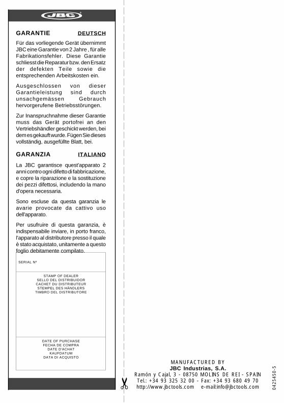
SERIAL Nº
MANUFACTURED BYJBC Industrias, S.A.
Ramón y Cajal, 3 - 08750 MOLINS DE REI - SPAINTel.: +34 93 325 32 00 - Fax: +34 93 680 49 70http://www.jbctools.com e-mail:[email protected] 04
2545
0-5